US11277154B2 - Polar code-based interleaving method and communication apparatus - Google Patents
Polar code-based interleaving method and communication apparatus Download PDFInfo
- Publication number
- US11277154B2 US11277154B2 US16/704,859 US201916704859A US11277154B2 US 11277154 B2 US11277154 B2 US 11277154B2 US 201916704859 A US201916704859 A US 201916704859A US 11277154 B2 US11277154 B2 US 11277154B2
- Authority
- US
- United States
- Prior art keywords
- matrix
- interleaving matrix
- interleaving
- log
- dimension
- Prior art date
- Legal status (The legal status is an assumption and is not a legal conclusion. Google has not performed a legal analysis and makes no representation as to the accuracy of the status listed.)
- Active, expires
Links
Images


Classifications
-
- H—ELECTRICITY
- H03—ELECTRONIC CIRCUITRY
- H03M—CODING; DECODING; CODE CONVERSION IN GENERAL
- H03M13/00—Coding, decoding or code conversion, for error detection or error correction; Coding theory basic assumptions; Coding bounds; Error probability evaluation methods; Channel models; Simulation or testing of codes
- H03M13/27—Coding, decoding or code conversion, for error detection or error correction; Coding theory basic assumptions; Coding bounds; Error probability evaluation methods; Channel models; Simulation or testing of codes using interleaving techniques
- H03M13/2792—Interleaver wherein interleaving is performed jointly with another technique such as puncturing, multiplexing or routing
-
- H—ELECTRICITY
- H04—ELECTRIC COMMUNICATION TECHNIQUE
- H04L—TRANSMISSION OF DIGITAL INFORMATION, e.g. TELEGRAPHIC COMMUNICATION
- H04L1/00—Arrangements for detecting or preventing errors in the information received
- H04L1/004—Arrangements for detecting or preventing errors in the information received by using forward error control
- H04L1/0056—Systems characterized by the type of code used
- H04L1/0071—Use of interleaving
-
- H—ELECTRICITY
- H03—ELECTRONIC CIRCUITRY
- H03M—CODING; DECODING; CODE CONVERSION IN GENERAL
- H03M13/00—Coding, decoding or code conversion, for error detection or error correction; Coding theory basic assumptions; Coding bounds; Error probability evaluation methods; Channel models; Simulation or testing of codes
- H03M13/03—Error detection or forward error correction by redundancy in data representation, i.e. code words containing more digits than the source words
- H03M13/05—Error detection or forward error correction by redundancy in data representation, i.e. code words containing more digits than the source words using block codes, i.e. a predetermined number of check bits joined to a predetermined number of information bits
- H03M13/13—Linear codes
-
- H—ELECTRICITY
- H03—ELECTRONIC CIRCUITRY
- H03M—CODING; DECODING; CODE CONVERSION IN GENERAL
- H03M13/00—Coding, decoding or code conversion, for error detection or error correction; Coding theory basic assumptions; Coding bounds; Error probability evaluation methods; Channel models; Simulation or testing of codes
- H03M13/27—Coding, decoding or code conversion, for error detection or error correction; Coding theory basic assumptions; Coding bounds; Error probability evaluation methods; Channel models; Simulation or testing of codes using interleaving techniques
- H03M13/2703—Coding, decoding or code conversion, for error detection or error correction; Coding theory basic assumptions; Coding bounds; Error probability evaluation methods; Channel models; Simulation or testing of codes using interleaving techniques the interleaver involving at least two directions
- H03M13/2717—Coding, decoding or code conversion, for error detection or error correction; Coding theory basic assumptions; Coding bounds; Error probability evaluation methods; Channel models; Simulation or testing of codes using interleaving techniques the interleaver involving at least two directions the interleaver involves 3 or more directions
-
- H—ELECTRICITY
- H04—ELECTRIC COMMUNICATION TECHNIQUE
- H04L—TRANSMISSION OF DIGITAL INFORMATION, e.g. TELEGRAPHIC COMMUNICATION
- H04L1/00—Arrangements for detecting or preventing errors in the information received
-
- H—ELECTRICITY
- H04—ELECTRIC COMMUNICATION TECHNIQUE
- H04L—TRANSMISSION OF DIGITAL INFORMATION, e.g. TELEGRAPHIC COMMUNICATION
- H04L1/00—Arrangements for detecting or preventing errors in the information received
- H04L1/004—Arrangements for detecting or preventing errors in the information received by using forward error control
- H04L1/0041—Arrangements at the transmitter end
-
- H—ELECTRICITY
- H04—ELECTRIC COMMUNICATION TECHNIQUE
- H04L—TRANSMISSION OF DIGITAL INFORMATION, e.g. TELEGRAPHIC COMMUNICATION
- H04L1/00—Arrangements for detecting or preventing errors in the information received
- H04L1/004—Arrangements for detecting or preventing errors in the information received by using forward error control
- H04L1/0056—Systems characterized by the type of code used
- H04L1/0057—Block codes
Definitions
- This application relates to the field of wireless communication technologies, and in particular, to a polar code-based interleaving method and apparatus.
- polar code (Polar Codes) put forward by Arikan based on channel polarization is selected for a channel encoding scheme, and the polar code has relatively low calculation complexity in coding and decoding.
- channel encoding is often used to improve reliability of data transmission, and an interleaving module is added to the channel encoding, so that anti-interference performance may be further improved.
- an interleaving module is added to the channel encoding, so that anti-interference performance may be further improved.
- a burst error is beyond an error-correcting capability of an error-correcting code, decreasing the error-correcting capability.
- a burst error is first discretized into a random error, and then the random error is corrected.
- an interleaving operation is performed on a polar code at a transmit end and a de-interleaving operation is performed at a receive end.
- a function of interleaving is disordering elements in an original data sequence, to weaken a correlation between data sequences before and after interleaving, and reduce impact of a data burst error, thereby improving anti-interference performance.
- a random interleaving manner is provided. According to the random interleaving manner, when an interleaved sequence is calculated offline, a permutation sequence needs to be recorded for use in interleaving and de-interleaving. When a code length is relatively long, an implementation process of reading a sequence obtained after random interleaving is relatively complex.
- Embodiments of this application provide a polar code-based interleaving method and apparatus, to resolve a problem existing in the prior art that when a code length is relatively long, an implementation process of reading a sequence obtained after random interleaving is relatively complex.
- this application provides a polar code-based interleaving method, including: determining an interleaving matrix based on a target code length M of a polar code; and interleaving, based on the interleaving matrix, encoded bits obtained after encoding of the polar code, to generate interleaved bits.
- the encoded bits obtained after the encoding of the polar code are interleaved by using the interleaving matrix determined based on the target code length M of the polar code, so that an implementation process of reading a sequence obtained after random interleaving is simple.
- the interleaving matrix is determined based on n unit matrices, and n is determined based on the target code length M.
- an implementation method for determining the interleaving matrix is simple.
- the interleaving matrix is determined by transposing a matrix obtained after n unit matrices are processed according to a specified algorithm, and n is determined based on the target code length M.
- the interleaving matrix that is simple and different from the interleaving matrix obtained by processing the n unit matrices according to the specified algorithm is determined.
- the interleaving matrix is determined by performing double-matrix superposition on an initial interleaving matrix.
- the interleaving matrix more complex than the initial interleaving matrix is determined, thereby further improving anti-interference performance.
- the interleaving matrix is determined by performing column bit order reversing or row bit order reversing on an initial interleaving matrix.
- the interleaving matrix more complex than the initial interleaving matrix is determined, thereby further improving anti-interference performance.
- the initial interleaving matrix is determined based on n unit matrices, or the initial interleaving matrix is determined by transposing a matrix obtained after n unit matrices are processed according to a specified algorithm, and n is determined based on the target code length M.
- a dimension of the interleaving matrix is determined according to a formula M ⁇ 3 log 2 (N) includes:
- n is equal to log 2 (N), and a dimension of the interleaving matrix that corresponds to M is determined in a pre-stored table of mapping between M and a dimension of the interleaving matrix.
- this application provides an interleaving apparatus, and the interleaving apparatus has a function of implementing behavior of an interleaving apparatus in the example of the method according to the first aspect.
- the function may be implemented by using hardware, or may be implemented by hardware executing corresponding software.
- the hardware or software includes one or more modules corresponding to the foregoing function.
- a structure of the interleaving apparatus includes a determining unit and a processing unit. These units may perform corresponding functions in the example of the foregoing method. For details, refer to detailed descriptions in the example of the method. The details are not repeated herein.
- this application provides a communications apparatus, including: a memory, configured to store a program; and a processor, configured to execute the program stored in the memory, where when the program is executed, the processor is configured to perform the method according to any one of the first aspect or the example designs of the first aspect.
- the computer-readable storage medium stores an instruction, and when the instruction is run on a computer, the computer is enabled to perform the method according to the foregoing aspects.
- Another aspect of this application provides a computer program product including an instruction.
- the instruction When the instruction is run on a computer, the computer is enabled to perform the method according to the foregoing aspects.
- Another aspect of this application provides a computer program, and when the computer program is run on a computer, the computer is enabled to perform the method according to the foregoing aspects.
- FIG. 1 is a flowchart of a polar code-based interleaving method according to an embodiment of this application;
- FIG. 2 is a schematic diagram of an interleaving matrix according to an embodiment of this application.
- FIG. 3 is a schematic diagram of another interleaving matrix according to an embodiment of this application.
- FIG. 4 is a schematic diagram of still another interleaving matrix according to an embodiment of this application.
- FIG. 5 is a schematic diagram of an interleaving matrix according to an embodiment of this application.
- FIG. 6 is a schematic diagram of an interleaving matrix according to an embodiment of this application.
- FIG. 7 is a schematic diagram of an interleaving matrix according to an embodiment of this application.
- FIG. 8 is a schematic diagram of an interleaving matrix according to an embodiment of this application.
- FIG. 9 is a schematic diagram of an interleaving matrix according to an embodiment of this application.
- FIG. 10 is a schematic diagram of an interleaving matrix according to an embodiment of this application.
- FIG. 11 is a schematic diagram of an interleaving matrix according to an embodiment of this application.
- FIG. 12 is a schematic diagram of an interleaving matrix according to an embodiment of this application.
- FIG. 13 is a schematic diagram of an apparatus according to an embodiment of this application.
- FIG. 14 is a schematic structural diagram of a communications apparatus according to an embodiment of this application.
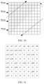
- FIG. 15 illustrates a table for determining a minimum dimension of an interleaving matrix corresponding to different code lengths.
- Embodiments of this application provide a polar code-based interleaving method and apparatus, to resolve a problem existing in the prior art that a relatively large storage space is required when a code length is relatively long.
- the method and the apparatus are based on a same inventive concept. Because problem-resolving principles for the method and the apparatus are similar, implementations of the apparatus and the method can be referenced to each other, and are not repeated for each implementation.
- the embodiments of this application are applicable to a channel encoding and decoding process.
- a polar code obtained after encoding is interleaved by using an interleaving matrix of an interleaver, and when a burst error occurs, the burst error is discretized into a random error, and then the random error is corrected, so that anti-interference performance of a system is improved.
- an implementation process of reading a sequence obtained after random interleaving is simplified.
- an interleaving matrix is determined based on a target code length M of a polar code; and encoded bits obtained after encoding of the polar code are interleaved based on the interleaving matrix, to generate interleaved bits.
- the encoded bits obtained after the encoding of the polar code are interleaved by using the interleaving matrix that is determined based on the target code length M of the polar code, so that an implementation process of reading a sequence obtained after the random interleaving is simplified.
- FIG. 1 is a flowchart of a polar code-based interleaving method according to this application. The method includes the following steps.
- the interleaving matrix is determined based on n unit matrices, and n is determined based on the target code length M.
- unit matrices are calculated according to a specified algorithm, and the specified algorithm may be a Kronecker product.
- the interleaving matrix is G.
- a location of 1 is used to store data, and a location of 0 does not store data.
- the interleaving matrix is G′.
- a location of 1 is used to store data, and a location of 0 does not store data.
- a manner of reading G′ is row-in and column-out.
- a dimension of the interleaving matrix may further be determined by using two manners below.
- n is equal to log 2 (N), and the dimension of the interleaving matrix is a minimum value of N that satisfies a formula M ⁇ 3 log 2 (N) .
- Pn is determined, when the remainder is 1, the dimension of the interleaving matrix is equal to the sum value plus 1; or when the remainder is 2 or 3, 2 is added to the sum value, or the sum value is adjusted to a prime number neighboring to the sum value, where the prime number is greater than the sum value.
- a specific embodiment provided based on Manner 2 is: A dimension of the interleaving matrix G N is reduced.
- n is equal to log 2 (N), and a dimension of the interleaving matrix that corresponds to M is determined in a pre-stored table of mapping between M and a dimension of the interleaving matrix.
- a specific embodiment provided based on Manner 3 is: In an ultra-reliable low latency communication (URLLC) scenario, a minimum dimension of an interleaving matrix corresponding to different code lengths, and a quantity of 1 in the corresponding interleaving matrix are determined based on Table 1, as shown in FIG. 15 , where a minimum dimension of the interleaving matrix is a minimum value of a dimension of the interleaving matrix, and a code length in the Table 1 is a common code length in an interleaving process.
- URLLC ultra-reliable low latency communication
- an order of data writing and data reading in the interleaving matrix is not limited in the present invention.
- the order may be in a row-in and column-out or row-in and row-out form as described in FIG. 4 , alternatively, may be in a column-in and row-out or column-in and column-out form as shown in FIG. 5 , or may be in a column-in and beveled-out or row-in and beveled-out form as shown in FIG. 6 .
- FIG. 5 and FIG. 6 shows a matrix obtained after data is written to the matrix shown in FIG. 2 .
- the interleaving matrix is determined by performing double-matrix superposition on an initial interleaving matrix.
- an interleaving matrix obtained after data is written to is double-matrix superposition on an initial interleaving matrix shown in FIG. 4 .
- a manner of data writing and reading in the interleaving matrix is row-in and column-out.
- another data writing and reading manner may be used. This is not limited in this embodiment of this application.
- a superposition manner or a reading manner of the interleaving matrix may alternatively be a manner shown in FIG. 8 , FIG. 9 , or FIG. 10 . These examples are shown by way of illustration and not limitation.
- the interleaving matrix is determined by performing column bit order reversing or row bit order reversing on an initial interleaving matrix.
- a bit order reversing operation is performed on the interleaving matrix to obtain [1 5 3 7 2 6 4 8], so that an interleaving matrix that is obtained after a column bit order reversing operation is performed and that is shown in FIG. 11 is determined, and an interleaving matrix that is obtained after a row bit order reversing operation is performed and that is shown in FIG. 12 is determined.
- the encoded bits obtained after the encoding of the polar code are interleaved by using the interleaving matrix that is determined based on the target code length M of the polar code, so that an implementation process of reading a sequence obtained after random interleaving is simple.
- this application further provides an interleaving apparatus, as shown in FIG. 13 .
- the interleaving apparatus includes a determining unit 1301 and a processing unit 1302 .
- the determining unit 1301 is configured to determine an interleaving matrix based on a target code length M of a polar code.
- the processing unit 1302 is configured to interleave, based on the interleaving matrix, encoded bits obtained after encoding of the polar code, to generate interleaved bits.
- the interleaving matrix is determined based on n unit matrices, n is determined based on the target code length M; or the interleaving matrix is determined by transposing a matrix obtained after the n unit matrices are processed according to a specified algorithm, and n is determined based on the target code length M.
- the interleaving matrix is determined by performing double-matrix superposition on an initial interleaving matrix; or in an example implementation, the interleaving matrix is determined by performing column bit order reversing or row bit order reversing on an initial interleaving matrix.
- the initial interleaving matrix is determined based on n unit matrices, or the initial interleaving matrix is determined by transposing a matrix obtained after the n unit matrices are processed based on a specified algorithm, and n is determined based on the target code length M.
- Pn is determined, when the remainder is 1, the dimension of the interleaving matrix is equal to the sum value plus 1; or when the remainder is 2 or 3, 2 is added to the sum value, or the sum value is adjusted to a prime number neighboring to the sum value, where the prime number is greater than the sum value.
- n is equal to log 2 (N), and a dimension of the interleaving matrix that corresponds to M is determined in a pre-stored table of mapping between M and a dimension of the interleaving matrix.
- the encoded bits obtained after the encoding of the polar code are interleaved by using the interleaving matrix that is determined based on the target code length M of the polar code, so that an implementation process of reading a sequence obtained after random interleaving is simple.
- FIG. 14 is a schematic structural diagram of a communications apparatus 1400 (for example, a communications apparatus such as an access point, a base station, a site, or a terminal device; or a chip in the foregoing communications apparatus) according to an embodiment of the present invention.
- a communications apparatus 1400 for example, a communications apparatus such as an access point, a base station, a site, or a terminal device; or a chip in the foregoing communications apparatus
- the communications apparatus 1400 may be implemented by using a bus 1401 as a general bus architecture.
- the bus 1401 may include any quantity of interconnected buses and bridges.
- the bus 1401 connects various circuits together.
- the circuits include a processor 1402 , a storage medium 1403 , and a bus interface 1404 .
- the communications apparatus 1400 is connected to a network adapter 1405 and the like through the bus 1401 by using the bus interface 1404 .
- the network adapter 1405 may be configured to: implement a signal processing function of a physical layer in a wireless communications network, and send and receive a radio frequency signal by using an antenna 1407 .
- a user interface 1406 may be connected to a user terminal, such as a keyboard, a display, a mouse, or a joystick.
- the bus 1401 may also connect other various circuits, such as a timing source, a peripheral device, a voltage regulator, or a power management circuit.
- the circuits are well-known in the art, and are not described in detail.
- the communications apparatus 1400 may be configured as a general-purpose processing system, for example, generally referred to as a chip.
- the general-purpose processing system includes: one or more microprocessors providing a processor function; and an external memory providing at least a part of the storage medium 1403 . All of these are connected to other support circuits by using an external bus system architecture.
- the communications apparatus 1400 may be implemented by using the following: an ASIC (application-specific integrated circuit) including the processor 1402 , the bus interface 1404 , and the user interface 1406 ; and at least a part of the storage medium 1403 that is integrated into a single chip.
- the communications apparatus 1400 may be implemented by using the following: one or more FPGAs (field programmable gate array), a PLD (programmable logic device), a controller, a state machine, gate logic, a discrete hardware component, any another suitable circuit, or any combination of circuits that are capable of performing the functions described in the entire specification of the present invention.
- the processor 1402 is responsible for bus management and general processing (including executing software stored in the storage medium 1403 ).
- the processor 1402 may be implemented by one or more general-purpose processors and/or special-purpose processors. Examples of the processor include a microprocessor, a microcontroller, a DSP processor, and another circuit that can execute the software.
- Software shall be construed broadly to mean instructions, data, or any combination thereof, whether referred to as software, firmware, middleware, microcode, hardware description language, or otherwise.
- the storage medium 1403 is separated from the processor 1402 .
- the storage medium 1403 or any part of the storage medium 1403 may be located outside the communications apparatus 1400 .
- the storage medium 1403 may include a transmission line, a carrier waveform modulated by using data, and/or a computer product separate from a wireless node.
- the media may be accessed by the processor 1402 by using the bus interface 1404 .
- the storage medium 1403 or the any part of the storage medium 1403 may be integrated into the processor 1402 .
- the storage medium 1403 may be a cache and/or a general-purpose register.
- the processor 1402 may perform the method in FIG. 1 above, and a performing process of the processor 1402 is not described herein again.
- units and method processes may be implemented by electronic hardware or a combination of computer software and electronic hardware. Whether the functions are performed by hardware or software depends on particular applications and design constraint conditions of the technical solutions. A person skilled in the art may use different methods to implement the described functions for each particular application.
- the disclosed apparatus and method may be implemented in other manners.
- the described apparatus embodiments are merely examples.
- the unit division is merely logical function division and may be other division in actual implementation.
- a plurality of units or components may be combined or may be integrated into another system, or some steps may be ignored, or may not be performed.
- coupling, direct coupling, or a communication connection between the units may be implemented by using some interfaces, and these may be in an electronic form, a mechanical form, or another form.
- the units that are described as separate components may or may not be physically separated, may be located in one place, or may be distributed to a plurality of networks units.
- All or some of the foregoing embodiments may be implemented by means of software, hardware, firmware, or any combination thereof.
- the embodiments may be implemented completely or partially in a form of a computer program product.
- the computer program product includes one or more computer instructions.
- the computer may be a general-purpose computer, a special-purpose computer, a computer network, or other programmable devices.
- the computer instructions may be stored in a computer-readable storage medium or may be transmitted from a computer-readable storage medium to another computer-readable storage medium.
- the computer instructions may be transmitted from a website, computer, server, or data center to another website, computer, server, or data center in a wired (for example, a coaxial cable, an optical fiber, or a digital subscriber line (DSL)) or wireless (for example, infrared, radio, and microwave, or the like) manner.
- the computer-readable storage medium may be any usable medium accessible by a computer, or a data storage device, such as a server or a data center, integrating one or more usable media.
- the usable medium may be a magnetic medium (for example, a floppy disk, a hard disk, or a magnetic tape), an optical medium (for example, a DVD), a semiconductor medium (for example, a solid state disk Solid State Disk (SSD)), or the like.
- a magnetic medium for example, a floppy disk, a hard disk, or a magnetic tape
- an optical medium for example, a DVD
- a semiconductor medium for example, a solid state disk Solid State Disk (SSD)
Landscapes
- Engineering & Computer Science (AREA)
- Physics & Mathematics (AREA)
- Probability & Statistics with Applications (AREA)
- Theoretical Computer Science (AREA)
- Computer Networks & Wireless Communication (AREA)
- Signal Processing (AREA)
- Error Detection And Correction (AREA)
Abstract
Description
n is equal to log2(N), and a dimension of the interleaving matrix that corresponds to M is determined in a pre-stored table of mapping between M and a dimension of the interleaving matrix.
M=2″, and M=N, n is equal to log2(N). In this case, then unit matrices are calculated according to a specified algorithm, and the specified algorithm may be a Kronecker product. Alternatively, the specified algorithm in this embodiment of this application may be a Tracy-Singh product, and the interleaving matrix GN=F⊗(log
n is equal to log2(N), and the dimension of the interleaving matrix is a minimum value of N that satisfies a formula M≥3log
n is equal to log2(N), and a maximum value of N that satisfies M≥3log
n is equal to log2(N), and a dimension of the interleaving matrix that corresponds to M is determined in a pre-stored table of mapping between M and a dimension of the interleaving matrix.
n is equal to log2(N), and a dimension of the interleaving matrix is a minimum value of N that satisfies a formula M≤3log
n is equal to log2(N), and a dimension of the interleaving matrix that corresponds to M is determined in a pre-stored table of mapping between M and a dimension of the interleaving matrix.
Claims (20)
Applications Claiming Priority (3)
| Application Number | Priority Date | Filing Date | Title |
|---|---|---|---|
| CN201710457819.4 | 2017-06-16 | ||
| CN201710457819.4A CN109150198B (en) | 2017-06-16 | 2017-06-16 | A kind of polar code interleaving processing method and device |
| PCT/CN2018/090880 WO2018228391A1 (en) | 2017-06-16 | 2018-06-12 | Polar code-based interleaving method and device |
Related Parent Applications (1)
| Application Number | Title | Priority Date | Filing Date |
|---|---|---|---|
| PCT/CN2018/090880 Continuation WO2018228391A1 (en) | 2017-06-16 | 2018-06-12 | Polar code-based interleaving method and device |
Publications (2)
| Publication Number | Publication Date |
|---|---|
| US20200153459A1 US20200153459A1 (en) | 2020-05-14 |
| US11277154B2 true US11277154B2 (en) | 2022-03-15 |
Family
ID=64659763
Family Applications (1)
| Application Number | Title | Priority Date | Filing Date |
|---|---|---|---|
| US16/704,859 Active 2038-08-20 US11277154B2 (en) | 2017-06-16 | 2019-12-05 | Polar code-based interleaving method and communication apparatus |
Country Status (4)
| Country | Link |
|---|---|
| US (1) | US11277154B2 (en) |
| EP (1) | EP3605900B1 (en) |
| CN (1) | CN109150198B (en) |
| WO (1) | WO2018228391A1 (en) |
Families Citing this family (1)
| Publication number | Priority date | Publication date | Assignee | Title |
|---|---|---|---|---|
| US11513897B2 (en) | 2020-12-28 | 2022-11-29 | Samsung Electronics Co., Ltd. | Error correction on length-compatible polar codes for memory systems |
Citations (19)
| Publication number | Priority date | Publication date | Assignee | Title |
|---|---|---|---|---|
| US6151690A (en) | 1997-01-31 | 2000-11-21 | Alcatel | Interleaving and de-interleaving method for digital data, interleaving and de-interleaving devices, and communication system |
| CN1399429A (en) | 2002-07-12 | 2003-02-26 | 信息产业部电信传输研究所 | TURBO coding and interleaving method and device for W-CDMA system |
| CN101034951A (en) | 2007-04-10 | 2007-09-12 | 中兴通讯股份有限公司 | Implementation method for in-Turbo code interweaver |
| CN101075857A (en) | 2007-04-29 | 2007-11-21 | 中兴通讯股份有限公司 | Method for generating turbo-code block intersection and HARQ packet |
| US7503046B2 (en) * | 2003-04-23 | 2009-03-10 | Micron Technology, Inc. | Method of obtaining interleave interval for two data values |
| CN101399554A (en) | 2007-09-30 | 2009-04-01 | 华为技术有限公司 | Interleaving method and de-interleaving method based on LDPC code and apparatus therefor |
| CN101540654A (en) | 2009-05-04 | 2009-09-23 | 普天信息技术研究院有限公司 | Method for interlacing rate matching and de-interlacing off-rate matching |
| CN102142928A (en) | 2010-11-19 | 2011-08-03 | 华为技术有限公司 | Methods for interleaving and deinterleaving external code coding output codons and interleaving and deinterleaving devices |
| US8638244B2 (en) * | 2009-08-31 | 2014-01-28 | Freescale Semiconductor, Inc. | Encoding module, apparatus and method for determining a position of a data bit within an interleaved data stream |
| US20140208183A1 (en) | 2013-01-23 | 2014-07-24 | Samsung Electronics Co., Ltd. | Method and system for encoding and decoding data using concatenated polar codes |
| US20140321575A1 (en) * | 2011-11-18 | 2014-10-30 | Nippon Hoso Kyokai | Transmission device, reception device, transmission method, and reception method |
| CN104219019A (en) | 2013-05-31 | 2014-12-17 | 华为技术有限公司 | Encoding method and encoding apparatus |
| WO2015139297A1 (en) | 2014-03-21 | 2015-09-24 | 华为技术有限公司 | Polar code rate-matching method and rate-matching device |
| WO2015143593A1 (en) | 2014-03-24 | 2015-10-01 | 华为技术有限公司 | Rate matching method and rate matching apparatus for polar codes |
| US9742440B2 (en) * | 2015-03-25 | 2017-08-22 | Samsung Electronics Co., Ltd | HARQ rate-compatible polar codes for wireless channels |
| US10171204B2 (en) * | 2016-05-13 | 2019-01-01 | Mediatek Inc. | Coded bit puncturing for polar codes |
| US10312946B2 (en) * | 2017-02-06 | 2019-06-04 | Mitsubishi Electric Research Laboratories, Inc. | Soft-output decoding of codewords encoded with polar code |
| US10461779B2 (en) * | 2015-08-12 | 2019-10-29 | Telefonaktiebolaget Lm Ericsson (Publ) | Rate-compatible polar codes |
| US10728080B2 (en) * | 2016-05-20 | 2020-07-28 | Qualcomm Incorporated | Polar codes and modulation mappings |
-
2017
- 2017-06-16 CN CN201710457819.4A patent/CN109150198B/en active Active
-
2018
- 2018-06-12 EP EP18817478.3A patent/EP3605900B1/en active Active
- 2018-06-12 WO PCT/CN2018/090880 patent/WO2018228391A1/en not_active Ceased
-
2019
- 2019-12-05 US US16/704,859 patent/US11277154B2/en active Active
Patent Citations (22)
| Publication number | Priority date | Publication date | Assignee | Title |
|---|---|---|---|---|
| US6151690A (en) | 1997-01-31 | 2000-11-21 | Alcatel | Interleaving and de-interleaving method for digital data, interleaving and de-interleaving devices, and communication system |
| CN1399429A (en) | 2002-07-12 | 2003-02-26 | 信息产业部电信传输研究所 | TURBO coding and interleaving method and device for W-CDMA system |
| US7503046B2 (en) * | 2003-04-23 | 2009-03-10 | Micron Technology, Inc. | Method of obtaining interleave interval for two data values |
| CN101034951A (en) | 2007-04-10 | 2007-09-12 | 中兴通讯股份有限公司 | Implementation method for in-Turbo code interweaver |
| CN101075857A (en) | 2007-04-29 | 2007-11-21 | 中兴通讯股份有限公司 | Method for generating turbo-code block intersection and HARQ packet |
| CN101399554A (en) | 2007-09-30 | 2009-04-01 | 华为技术有限公司 | Interleaving method and de-interleaving method based on LDPC code and apparatus therefor |
| CN101540654A (en) | 2009-05-04 | 2009-09-23 | 普天信息技术研究院有限公司 | Method for interlacing rate matching and de-interlacing off-rate matching |
| US8638244B2 (en) * | 2009-08-31 | 2014-01-28 | Freescale Semiconductor, Inc. | Encoding module, apparatus and method for determining a position of a data bit within an interleaved data stream |
| CN102142928A (en) | 2010-11-19 | 2011-08-03 | 华为技术有限公司 | Methods for interleaving and deinterleaving external code coding output codons and interleaving and deinterleaving devices |
| US20140321575A1 (en) * | 2011-11-18 | 2014-10-30 | Nippon Hoso Kyokai | Transmission device, reception device, transmission method, and reception method |
| US20140208183A1 (en) | 2013-01-23 | 2014-07-24 | Samsung Electronics Co., Ltd. | Method and system for encoding and decoding data using concatenated polar codes |
| CN104219019A (en) | 2013-05-31 | 2014-12-17 | 华为技术有限公司 | Encoding method and encoding apparatus |
| US20190268025A1 (en) | 2013-05-31 | 2019-08-29 | Huawei Technologies Co., Ltd. | Coding Method and Coding Device |
| WO2015139297A1 (en) | 2014-03-21 | 2015-09-24 | 华为技术有限公司 | Polar code rate-matching method and rate-matching device |
| US20170012739A1 (en) | 2014-03-21 | 2017-01-12 | Huawei Technologies Co., Ltd. | Polar code rate matching method and apparatus |
| WO2015143593A1 (en) | 2014-03-24 | 2015-10-01 | 华为技术有限公司 | Rate matching method and rate matching apparatus for polar codes |
| US20170012740A1 (en) | 2014-03-24 | 2017-01-12 | Huawei Technologies Co., Ltd. | Polar code rate matching method and polar code rate matching apparatus |
| US9742440B2 (en) * | 2015-03-25 | 2017-08-22 | Samsung Electronics Co., Ltd | HARQ rate-compatible polar codes for wireless channels |
| US10461779B2 (en) * | 2015-08-12 | 2019-10-29 | Telefonaktiebolaget Lm Ericsson (Publ) | Rate-compatible polar codes |
| US10171204B2 (en) * | 2016-05-13 | 2019-01-01 | Mediatek Inc. | Coded bit puncturing for polar codes |
| US10728080B2 (en) * | 2016-05-20 | 2020-07-28 | Qualcomm Incorporated | Polar codes and modulation mappings |
| US10312946B2 (en) * | 2017-02-06 | 2019-06-04 | Mitsubishi Electric Research Laboratories, Inc. | Soft-output decoding of codewords encoded with polar code |
Non-Patent Citations (6)
| Title |
|---|
| "Identity matrix," Wikipedia, XP055677295, total 2 pages, (Mar. 17, 2020). |
| "Interleaver design for Polar codes," 3GPP TSG-RAN WG1 Meeting #89, Hangzhou, China, R1-1708649, XP051273836, total 5 pages, 3rd Generation Partnership Project, Valbonne, France (May 15-19, 2017). |
| D'Azzo et al.,"Analysis and Design of Linear Control System Based on MATLAB," Mechanical Industry Press (2008). With English Abstract. |
| Gou et al., "The Common Interleaving Technology in Turbo Codes," with an English abstract, total 3 pages, (Mar. 2003). |
| Jin et al., "Performance of polar coding for the power line communications in the presence of impulsive noise," IET Communications, vol. 9, No. 17, pp. 2101-2106, (Jul. 17, 2015). |
| QUALCOMM INCORPORATED: "Interleaver design for Polar codes", 3GPP DRAFT; R1-1708649 INTERLEAVER DESIGN FOR POLAR CODES, 3RD GENERATION PARTNERSHIP PROJECT (3GPP), MOBILE COMPETENCE CENTRE ; 650, ROUTE DES LUCIOLES ; F-06921 SOPHIA-ANTIPOLIS CEDEX ; FRANCE, vol. RAN WG1, no. Hangzhou; 20170515 - 20170519, R1-1708649 Interleaver design for Polar codes, 14 May 2017 (2017-05-14), Mobile Competence Centre ; 650, route des Lucioles ; F-06921 Sophia-Antipolis Cedex ; France , XP051273836 |
Also Published As
| Publication number | Publication date |
|---|---|
| WO2018228391A1 (en) | 2018-12-20 |
| EP3605900A1 (en) | 2020-02-05 |
| US20200153459A1 (en) | 2020-05-14 |
| CN109150198B (en) | 2021-05-14 |
| EP3605900A4 (en) | 2020-04-29 |
| CN109150198A (en) | 2019-01-04 |
| EP3605900B1 (en) | 2024-07-31 |
Similar Documents
| Publication | Publication Date | Title |
|---|---|---|
| US10554224B2 (en) | Method and apparatus for processing data with polar encoding | |
| US8533572B2 (en) | Error correcting code logic for processor caches that uses a common set of check bits | |
| US8938664B2 (en) | Error correction decoding by trial and error | |
| CN102117662B (en) | Error correction mechanisms for 8-bit memory devices | |
| US11075652B2 (en) | Polar code transmission method and apparatus | |
| US12019516B2 (en) | Instant write scheme with delayed parity/raid | |
| US11184034B2 (en) | Method and device for decoding staircase code, and storage medium | |
| US11277154B2 (en) | Polar code-based interleaving method and communication apparatus | |
| CN110535476B (en) | Method, device, computer equipment and storage medium for optimizing soft information storage of LDPC soft decoder | |
| KR101374430B1 (en) | Data line storage and transmission utilizing both error correcting code and synchronization information | |
| US20200220652A1 (en) | Apparatus that receives non-binary polar code and decoding method thereof | |
| EP3737013B1 (en) | Encoding method, decoding method and device | |
| US20240323927A1 (en) | Channel coding method and apparatus | |
| TWI503833B (en) | A method of detecting and correcting errors with bch engines for flash storage system | |
| CN101494518B (en) | Packet Processing Method for Wireless Communication | |
| WO2019096124A1 (en) | Cyclic redundancy check (crc) calculation method and device | |
| TWI501083B (en) | A method of detecting and correcting errors with bch and ldpc engines for flash storage system | |
| CN120256190A (en) | Data processing method, processing node, data processing system and storage medium | |
| CN109412610B (en) | Encoding method, decoding method, encoding device and decoding device | |
| CN120377934A (en) | Code construction method, coding method, node repairing method and data processing device | |
| US10114569B2 (en) | Computing system with shift expandable coding mechanism and method of operation thereof | |
| CN117200807A (en) | Data processing method and device, electronic equipment and storage medium | |
| CN113934363A (en) | Method for coding data, method and device for decoding data | |
| WO2006027742A1 (en) | Fault tolerant bus |
Legal Events
| Date | Code | Title | Description |
|---|---|---|---|
| FEPP | Fee payment procedure |
Free format text: ENTITY STATUS SET TO UNDISCOUNTED (ORIGINAL EVENT CODE: BIG.); ENTITY STATUS OF PATENT OWNER: LARGE ENTITY |
|
| STPP | Information on status: patent application and granting procedure in general |
Free format text: DOCKETED NEW CASE - READY FOR EXAMINATION |
|
| STPP | Information on status: patent application and granting procedure in general |
Free format text: NON FINAL ACTION MAILED |
|
| AS | Assignment |
Owner name: HUAWEI TECHNOLOGIES CO., LTD., CHINA Free format text: ASSIGNMENT OF ASSIGNORS INTEREST;ASSIGNORS:WANG, GUIJIE;LI, RONG;WANG, JUN;AND OTHERS;SIGNING DATES FROM 20200520 TO 20210322;REEL/FRAME:056023/0082 |
|
| STPP | Information on status: patent application and granting procedure in general |
Free format text: RESPONSE TO NON-FINAL OFFICE ACTION ENTERED AND FORWARDED TO EXAMINER |
|
| STPP | Information on status: patent application and granting procedure in general |
Free format text: NON FINAL ACTION MAILED |
|
| STPP | Information on status: patent application and granting procedure in general |
Free format text: RESPONSE TO NON-FINAL OFFICE ACTION ENTERED AND FORWARDED TO EXAMINER |
|
| STPP | Information on status: patent application and granting procedure in general |
Free format text: NOTICE OF ALLOWANCE MAILED -- APPLICATION RECEIVED IN OFFICE OF PUBLICATIONS |
|
| STCF | Information on status: patent grant |
Free format text: PATENTED CASE |
|
| MAFP | Maintenance fee payment |
Free format text: PAYMENT OF MAINTENANCE FEE, 4TH YEAR, LARGE ENTITY (ORIGINAL EVENT CODE: M1551); ENTITY STATUS OF PATENT OWNER: LARGE ENTITY Year of fee payment: 4 |