US11275385B2 - Driving support device, storage medium, and driving support method - Google Patents
Driving support device, storage medium, and driving support method Download PDFInfo
- Publication number
- US11275385B2 US11275385B2 US16/269,922 US201916269922A US11275385B2 US 11275385 B2 US11275385 B2 US 11275385B2 US 201916269922 A US201916269922 A US 201916269922A US 11275385 B2 US11275385 B2 US 11275385B2
- Authority
- US
- United States
- Prior art keywords
- vehicle
- driving support
- estimated
- accuracy
- degree
- Prior art date
- Legal status (The legal status is an assumption and is not a legal conclusion. Google has not performed a legal analysis and makes no representation as to the accuracy of the status listed.)
- Active, expires
Links
Images


Classifications
-
- G—PHYSICS
- G05—CONTROLLING; REGULATING
- G05D—SYSTEMS FOR CONTROLLING OR REGULATING NON-ELECTRIC VARIABLES
- G05D1/00—Control of position, course, altitude or attitude of land, water, air or space vehicles, e.g. using automatic pilots
- G05D1/02—Control of position or course in two dimensions
- G05D1/021—Control of position or course in two dimensions specially adapted to land vehicles
- G05D1/0287—Control of position or course in two dimensions specially adapted to land vehicles involving a plurality of land vehicles, e.g. fleet or convoy travelling
- G05D1/0289—Control of position or course in two dimensions specially adapted to land vehicles involving a plurality of land vehicles, e.g. fleet or convoy travelling with means for avoiding collisions between vehicles
-
- G—PHYSICS
- G08—SIGNALLING
- G08G—TRAFFIC CONTROL SYSTEMS
- G08G1/00—Traffic control systems for road vehicles
- G08G1/16—Anti-collision systems
- G08G1/166—Anti-collision systems for active traffic, e.g. moving vehicles, pedestrians, bikes
-
- B—PERFORMING OPERATIONS; TRANSPORTING
- B60—VEHICLES IN GENERAL
- B60W—CONJOINT CONTROL OF VEHICLE SUB-UNITS OF DIFFERENT TYPE OR DIFFERENT FUNCTION; CONTROL SYSTEMS SPECIALLY ADAPTED FOR HYBRID VEHICLES; ROAD VEHICLE DRIVE CONTROL SYSTEMS FOR PURPOSES NOT RELATED TO THE CONTROL OF A PARTICULAR SUB-UNIT
- B60W30/00—Purposes of road vehicle drive control systems not related to the control of a particular sub-unit, e.g. of systems using conjoint control of vehicle sub-units
- B60W30/18—Propelling the vehicle
- B60W30/182—Selecting between different operative modes, e.g. comfort and performance modes
-
- G—PHYSICS
- G01—MEASURING; TESTING
- G01C—MEASURING DISTANCES, LEVELS OR BEARINGS; SURVEYING; NAVIGATION; GYROSCOPIC INSTRUMENTS; PHOTOGRAMMETRY OR VIDEOGRAMMETRY
- G01C21/00—Navigation; Navigational instruments not provided for in groups G01C1/00 - G01C19/00
- G01C21/10—Navigation; Navigational instruments not provided for in groups G01C1/00 - G01C19/00 by using measurements of speed or acceleration
- G01C21/12—Navigation; Navigational instruments not provided for in groups G01C1/00 - G01C19/00 by using measurements of speed or acceleration executed aboard the object being navigated; Dead reckoning
- G01C21/16—Navigation; Navigational instruments not provided for in groups G01C1/00 - G01C19/00 by using measurements of speed or acceleration executed aboard the object being navigated; Dead reckoning by integrating acceleration or speed, i.e. inertial navigation
-
- G—PHYSICS
- G01—MEASURING; TESTING
- G01C—MEASURING DISTANCES, LEVELS OR BEARINGS; SURVEYING; NAVIGATION; GYROSCOPIC INSTRUMENTS; PHOTOGRAMMETRY OR VIDEOGRAMMETRY
- G01C21/00—Navigation; Navigational instruments not provided for in groups G01C1/00 - G01C19/00
- G01C21/26—Navigation; Navigational instruments not provided for in groups G01C1/00 - G01C19/00 specially adapted for navigation in a road network
- G01C21/34—Route searching; Route guidance
- G01C21/3453—Special cost functions, i.e. other than distance or default speed limit of road segments
- G01C21/3476—Special cost functions, i.e. other than distance or default speed limit of road segments using point of interest [POI] information, e.g. a route passing visible POIs
-
- G—PHYSICS
- G01—MEASURING; TESTING
- G01C—MEASURING DISTANCES, LEVELS OR BEARINGS; SURVEYING; NAVIGATION; GYROSCOPIC INSTRUMENTS; PHOTOGRAMMETRY OR VIDEOGRAMMETRY
- G01C21/00—Navigation; Navigational instruments not provided for in groups G01C1/00 - G01C19/00
- G01C21/26—Navigation; Navigational instruments not provided for in groups G01C1/00 - G01C19/00 specially adapted for navigation in a road network
- G01C21/34—Route searching; Route guidance
- G01C21/36—Input/output arrangements for on-board computers
- G01C21/3691—Retrieval, searching and output of information related to real-time traffic, weather, or environmental conditions
-
- G—PHYSICS
- G05—CONTROLLING; REGULATING
- G05D—SYSTEMS FOR CONTROLLING OR REGULATING NON-ELECTRIC VARIABLES
- G05D1/00—Control of position, course, altitude or attitude of land, water, air or space vehicles, e.g. using automatic pilots
- G05D1/02—Control of position or course in two dimensions
- G05D1/021—Control of position or course in two dimensions specially adapted to land vehicles
- G05D1/0212—Control of position or course in two dimensions specially adapted to land vehicles with means for defining a desired trajectory
- G05D1/0214—Control of position or course in two dimensions specially adapted to land vehicles with means for defining a desired trajectory in accordance with safety or protection criteria, e.g. avoiding hazardous areas
-
- G—PHYSICS
- G05—CONTROLLING; REGULATING
- G05D—SYSTEMS FOR CONTROLLING OR REGULATING NON-ELECTRIC VARIABLES
- G05D1/00—Control of position, course, altitude or attitude of land, water, air or space vehicles, e.g. using automatic pilots
- G05D1/02—Control of position or course in two dimensions
- G05D1/021—Control of position or course in two dimensions specially adapted to land vehicles
- G05D1/0231—Control of position or course in two dimensions specially adapted to land vehicles using optical position detecting means
- G05D1/0246—Control of position or course in two dimensions specially adapted to land vehicles using optical position detecting means using a video camera in combination with image processing means
-
- G—PHYSICS
- G05—CONTROLLING; REGULATING
- G05D—SYSTEMS FOR CONTROLLING OR REGULATING NON-ELECTRIC VARIABLES
- G05D1/00—Control of position, course, altitude or attitude of land, water, air or space vehicles, e.g. using automatic pilots
- G05D1/02—Control of position or course in two dimensions
- G05D1/021—Control of position or course in two dimensions specially adapted to land vehicles
- G05D1/0268—Control of position or course in two dimensions specially adapted to land vehicles using internal positioning means
- G05D1/0272—Control of position or course in two dimensions specially adapted to land vehicles using internal positioning means comprising means for registering the travel distance, e.g. revolutions of wheels
-
- G—PHYSICS
- G08—SIGNALLING
- G08G—TRAFFIC CONTROL SYSTEMS
- G08G1/00—Traffic control systems for road vehicles
- G08G1/123—Traffic control systems for road vehicles indicating the position of vehicles, e.g. scheduled vehicles; Managing passenger vehicles circulating according to a fixed timetable, e.g. buses, trains, trams
- G08G1/133—Traffic control systems for road vehicles indicating the position of vehicles, e.g. scheduled vehicles; Managing passenger vehicles circulating according to a fixed timetable, e.g. buses, trains, trams within the vehicle ; Indicators inside the vehicles or at stops
-
- G—PHYSICS
- G08—SIGNALLING
- G08G—TRAFFIC CONTROL SYSTEMS
- G08G1/00—Traffic control systems for road vehicles
- G08G1/16—Anti-collision systems
- G08G1/161—Decentralised systems, e.g. inter-vehicle communication
- G08G1/163—Decentralised systems, e.g. inter-vehicle communication involving continuous checking
-
- B—PERFORMING OPERATIONS; TRANSPORTING
- B60—VEHICLES IN GENERAL
- B60W—CONJOINT CONTROL OF VEHICLE SUB-UNITS OF DIFFERENT TYPE OR DIFFERENT FUNCTION; CONTROL SYSTEMS SPECIALLY ADAPTED FOR HYBRID VEHICLES; ROAD VEHICLE DRIVE CONTROL SYSTEMS FOR PURPOSES NOT RELATED TO THE CONTROL OF A PARTICULAR SUB-UNIT
- B60W2420/00—Indexing codes relating to the type of sensors based on the principle of their operation
- B60W2420/40—Photo, light or radio wave sensitive means, e.g. infrared sensors
- B60W2420/403—Image sensing, e.g. optical camera
-
- B—PERFORMING OPERATIONS; TRANSPORTING
- B60—VEHICLES IN GENERAL
- B60W—CONJOINT CONTROL OF VEHICLE SUB-UNITS OF DIFFERENT TYPE OR DIFFERENT FUNCTION; CONTROL SYSTEMS SPECIALLY ADAPTED FOR HYBRID VEHICLES; ROAD VEHICLE DRIVE CONTROL SYSTEMS FOR PURPOSES NOT RELATED TO THE CONTROL OF A PARTICULAR SUB-UNIT
- B60W2420/00—Indexing codes relating to the type of sensors based on the principle of their operation
- B60W2420/40—Photo, light or radio wave sensitive means, e.g. infrared sensors
- B60W2420/408—Radar; Laser, e.g. lidar
-
- B—PERFORMING OPERATIONS; TRANSPORTING
- B60—VEHICLES IN GENERAL
- B60W—CONJOINT CONTROL OF VEHICLE SUB-UNITS OF DIFFERENT TYPE OR DIFFERENT FUNCTION; CONTROL SYSTEMS SPECIALLY ADAPTED FOR HYBRID VEHICLES; ROAD VEHICLE DRIVE CONTROL SYSTEMS FOR PURPOSES NOT RELATED TO THE CONTROL OF A PARTICULAR SUB-UNIT
- B60W2556/00—Input parameters relating to data
- B60W2556/25—Data precision
-
- B—PERFORMING OPERATIONS; TRANSPORTING
- B60—VEHICLES IN GENERAL
- B60W—CONJOINT CONTROL OF VEHICLE SUB-UNITS OF DIFFERENT TYPE OR DIFFERENT FUNCTION; CONTROL SYSTEMS SPECIALLY ADAPTED FOR HYBRID VEHICLES; ROAD VEHICLE DRIVE CONTROL SYSTEMS FOR PURPOSES NOT RELATED TO THE CONTROL OF A PARTICULAR SUB-UNIT
- B60W30/00—Purposes of road vehicle drive control systems not related to the control of a particular sub-unit, e.g. of systems using conjoint control of vehicle sub-units
- B60W30/08—Active safety systems predicting or avoiding probable or impending collision or attempting to minimise its consequences
- B60W30/09—Taking automatic action to avoid collision, e.g. braking and steering
-
- B—PERFORMING OPERATIONS; TRANSPORTING
- B60—VEHICLES IN GENERAL
- B60W—CONJOINT CONTROL OF VEHICLE SUB-UNITS OF DIFFERENT TYPE OR DIFFERENT FUNCTION; CONTROL SYSTEMS SPECIALLY ADAPTED FOR HYBRID VEHICLES; ROAD VEHICLE DRIVE CONTROL SYSTEMS FOR PURPOSES NOT RELATED TO THE CONTROL OF A PARTICULAR SUB-UNIT
- B60W30/00—Purposes of road vehicle drive control systems not related to the control of a particular sub-unit, e.g. of systems using conjoint control of vehicle sub-units
- B60W30/10—Path keeping
- B60W30/12—Lane keeping
-
- B—PERFORMING OPERATIONS; TRANSPORTING
- B60—VEHICLES IN GENERAL
- B60W—CONJOINT CONTROL OF VEHICLE SUB-UNITS OF DIFFERENT TYPE OR DIFFERENT FUNCTION; CONTROL SYSTEMS SPECIALLY ADAPTED FOR HYBRID VEHICLES; ROAD VEHICLE DRIVE CONTROL SYSTEMS FOR PURPOSES NOT RELATED TO THE CONTROL OF A PARTICULAR SUB-UNIT
- B60W30/00—Purposes of road vehicle drive control systems not related to the control of a particular sub-unit, e.g. of systems using conjoint control of vehicle sub-units
- B60W30/14—Adaptive cruise control
- B60W30/16—Control of distance between vehicles, e.g. keeping a distance to preceding vehicle
-
- G05D2201/0213—
Definitions
- the present disclosure relates to driving support.
- the traveling trajectory of an own vehicle is estimated based on vehicle speed, steering angle, and yaw rate sensors. Furthermore, this method estimates the traveling trajectory of another vehicle based on the change in past position information of the other vehicle, and corrects the estimated traveling trajectory based on the change of the estimated past traveling trajectory.
- the driving support device estimates a position of the own vehicle using a detection result by an internal sensor and position information of landmarks in the vicinity of the own vehicle and selects an operating mode of the driving support according to the accuracy of the estimated position of the own vehicle.
- FIG. 1 is a block configuration diagram illustrating the internal structure of a vehicle
- FIG. 2 is a diagram illustrating a sensing range of external sensors
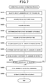
- FIG. 3 is a flowchart illustrating a driving support process
- FIG. 4 is a flowchart illustrating an operating mode selection process
- FIG. 5 is a diagram illustrating a method of calculating a position, traveling direction, traveling speed and angular velocity of a vehicle
- FIG. 6 is a diagram illustrating an environmental map including landmarks in the vicinity of an own vehicle and another vehicle
- FIG. 7 is a flowchart illustrating a correction accuracy estimation process
- FIG. 8 is a flowchart illustrating an odometry accuracy estimation process
- FIG. 9 is a flowchart illustrating a driving support process according to a second embodiment.
- the inventor of the present disclosure has studied the following technique as a driving support technique capable of appropriately performing driving support.
- JP 2007-317018 A Japanese Patent Application No. 2007-317018
- the traveling trajectory of an own vehicle is estimated only by odometry using internal sensors, and is not corrected. Therefore, the estimation accuracy of the traveling trajectory may be low. In the case where the accuracy of the traveling trajectory is low, the accuracy of the collision determination may also be low.
- This kind of problem is common to all driving support using position estimation of an own vehicle. Based on the above, an object of the present disclosure is to solve this problem by appropriately implementing driving support using position estimation of an own vehicle.
- One aspect of the driving support device is a driving support device mounted in a vehicle that includes: an acquiring device for acquiring position information of landmarks around an own vehicle; an internal sensor for detecting state quantities related to a traveling state of the own vehicle; and an actuator for performing driving support; the driving support device, including a first estimating unit for estimating a position of the own vehicle by dead reckoning using position information of the landmarks and a detection result by the internal sensor; a second estimating unit for estimating an estimation accuracy by the first estimating unit using the position information of the landmarks used by the first estimating unit; a selecting unit for selecting an operating mode of driving support provided by the actuator using the estimation accuracy estimated by the second estimation unit; and a support unit for executing a process for driving support according to the selected operation mode.
- the vehicle 10 includes acquiring devices 20 , a route guiding device 45 , internal sensors 50 , actuators 80 , and an ECU 90 .
- the vehicle 10 is, for example, a four-wheeled automobile.
- the acquiring devices 20 include external sensors 30 and a communication device 40 .
- the information acquired by the acquiring devices 20 is collectively referred to as acquired information.
- the communication device 40 executes road-to-vehicle communication.
- the external sensors 30 include a front radar 31 , two front-side radars 32 , two rear-side radars 33 , a front camera 34 , and a rear camera 35 .
- the forward radar 31 is a millimeter wave radar with a frequency of 77 GHz.
- Both the front-side radars 32 and the rear-side radars 33 are millimeter wave radars with a frequency of 24 GHz.
- Both the front camera 34 and the rear camera 35 are monocular cameras.
- the external sensors 30 are not limited to these sensors.
- the front radar 31 senses a range centered in front of the vehicle 10 (for example, a range of ⁇ 45 degrees).
- the front-side radars 32 sense a range centered on the front sides of the vehicle 10 (for example, a range of ⁇ 45 degrees).
- the front side of the vehicle 10 is the range centered on the right front oblique 45 degrees of the vehicle 10 and the range centered on the left front oblique 45 degrees.
- the rear-side radars 33 sense a range centered on the rear sides of the vehicle 10 (for example, a range of ⁇ 45 degrees).
- the rear side of the vehicle 10 is the range centered on the right rear oblique 45 degrees of the vehicle 10 and the range centered on the left rear oblique 45 degrees.
- the imaging range of the front camera 34 is a range centered on the front of the vehicle 10 .
- the imaging range of the front camera 35 is a range centered on the rear of the vehicle 10 .
- the sensing range of the radar and the imaging range of the camera are not limited to the above ranges.
- the route guiding device 45 performs route guidance for the driver.
- the route guiding device 45 acquires information related to the road and information related to the weather from the outside through communication and inputs the information to the ECU 90 . These items of information will be described later together with the odometry accuracy estimation process illustrated in FIG. 8 .
- the internal sensors 50 include sensors for detecting the state quantities related to the traveling state of the vehicle.
- the internal sensors 50 include a steering angle sensor 51 for detecting the steering angle of the vehicle 10 , a yaw rate sensor 52 for detecting the yaw rate of the vehicle 10 , and a wheel speed sensor 53 for acquiring the rotational speed of the wheels.
- the actuators 80 include a braking device 81 , a warning device 82 , a driving mechanism 83 , and a steering mechanism 84 .
- the braking device 81 includes a foot brake and a brake ECU.
- the foot brake is a brake mechanism for braking in accordance with the depression amount of a brake pedal. Even though the brake pedal is not depressed, the brake ECU actuates the foot brake when instructed by the ECU 90 . For example, the ECU 90 sends a control signal to the brake ECU to actuate the foot brake. Functioning of the foot brake in this way is called automatic braking.
- the warning device 82 warns the driver about a risk of collision.
- the warning by the warning device 82 includes at least one of an output of a warning sound, a tightening of a seat belt, and a display by a head-up display.
- the driving mechanism 83 includes an engine, an accelerator pedal, and at least one ECU.
- engine referred to here is used in a comprehensive sense including at least one of an internal combustion engine and an electric motor.
- the ECU included in the driving mechanism 83 operates the engine in accordance with the depression amount of the accelerator pedal or an instruction from the ECU 90 .
- the ECU 90 sends a control signal to the ECU included in the driving mechanism 83 to operate the engine.
- the steering mechanism 84 includes a steering wheel, a motor for electric power steering, and a steering ECU.
- the steering ECU drives the motor in accordance with the rotation amount of the steering wheel or an instruction from the ECU 90 .
- the ECU 90 sends a control signal to the steering ECU to drive the motor.
- the ECU 90 includes a processor 91 and a storage medium 92 .
- the storage medium 92 is, for example, a non-transitory tangible computer-readable storage medium such as a semiconductor memory.
- the storage medium 92 stores a program for realizing a driving support process (described later).
- the processor 91 executes a program stored in the storage medium 92
- the ECU 90 executes a process for realizing the driving support method.
- the driving support process illustrated in FIG. 3 is repeatedly executed by the ECU 90 while the vehicle 10 is traveling. More specifically, the driving support process in the present embodiment is a collision avoidance support process.
- the ECU 90 executes an operating mode selection process as S 10 .
- the ECU 90 proceeds to S 100 and executes self-position estimation using odometry. More specifically, as illustrated in FIG. 5 , the position of an own vehicle by dead reckoning (hereinafter referred to as self-position), the traveling direction of the own vehicle, the traveling speed of the own vehicle, and the angular velocity of the own vehicle are calculated using the values acquired by the internal sensors 50 and the previous estimated values.
- the arrow in front of the vehicle 10 illustrated in FIG. 5 is a speed vector that represents the traveling direction and the traveling speed of the vehicle 10 .
- the circular arrow on the vehicle 10 illustrated in FIG. 5 represents the angular velocity of the vehicle 10 .
- the X mark on the vehicle 10 illustrated in FIG. 5 represents the self-position of the vehicle 10 .
- all values acquired by the steering angle sensor 51 , the yaw rate sensor 52 , and the wheel speed sensor 53 are used as values acquired by the internal sensors 50 .
- only a part of the acquired values of the steering angle sensor 51 , the yaw rate sensor 52 , and the wheel speed sensor 53 may be used.
- only the acquired values of the yaw rate sensor 52 and the wheel speed sensor 53 may be used.
- the self-position of a vehicle may be represented by latitude and longitude or in the XY coordinate system.
- This XY coordinate system is the world coordinate system.
- the origin of the XY coordinate system is, for example, a position where a push start switch of the vehicle 10 is pressed.
- the push start switch is a user interface for switching between a parked state and a traveling enabled state.
- the push start switch is also called a power switch.
- the ECU 90 proceeds to S 200 and determines whether at least one landmark is being detected.
- the landmark referred to here is an object that can be used for SLAM.
- SLAM is an acronym for “Simultaneous Localization And Mapping”, which is a method of simultaneously performing self-location estimation and environmental map creation.
- the environment map in the present embodiment is expressed in two dimensions indicating the position in the horizontal direction.
- the ECU 90 stores the created environmental map in the storage medium 92 .
- the SLAM used in this embodiment is EKF-SLAM.
- EKF is an acronym for “Extended Kalman Filter”, which is an extended Kalman filter.
- the ECU 90 in the present embodiment detects landmarks using information acquired by the front radar 31 , the front-side radars 32 , and the rear-side radars 33 .
- a landmark may be detected based on information acquired by the front camera 34 or the rear camera 35 , information acquired by LIDAR, map information, information acquired by inter-vehicle communication, information acquired by road-to-vehicle communication, or the like, or a landmark may be detected by a combination of these.
- LIDAR and is an abbreviation for “Light Detection And Ranging”. LIDAR is a type of radar.
- the error range In the error range, combinations of Es and numbers are given as symbols.
- the number included in the code attached to the error range coincides with the number included in the code indicating the landmark.
- the X mark attached to the vehicle 10 is the self-position of the vehicle 10 estimated by S 100 , or in other words, is the deal-reckoning position before correction.
- the ECU 90 determines NO in S 200 and the process proceeds to S 600 to be described later. Note that the landmarks detected in the past are appropriately deleted or stored as will be described later. The deletion of a landmark will be described later. Even in the case where no landmark is detected, when at least one landmark detected in the past is stored, the environment map is retained.
- the ECU 90 determines YES in S 200 and the process proceeds to S 300 .
- the ECU 90 corrects the deal-reckoning position estimated in S 100 using the SLAM and updates the environment map.
- Updating of the environment map referred to here means that in addition to correcting the position information of the landmarks with respect to the self-position of a vehicle, position information of landmarks is appropriately added and deleted.
- SLAM when there is information of landmarks located in front of the vehicle and relatively near an own vehicle, it is possible to improve accuracy of estimating the self-position. Therefore, information is deleted from the environment map for landmarks that the vehicle has passed by or landmarks for which a predetermined period of time has elapsed since detection. For example, in the present embodiment, information of a landmark located near an intersection is deleted when the vehicle leaves the intersection.
- the ECU 90 proceeds to S 400 and executes a correction accuracy estimation process. As illustrated in FIG. 7 , when the correction accuracy estimation process is started, the ECU 90 proceeds to S 410 and selects one of the landmarks that has not yet been focused on.
- the landmarks L 1 , L 2 are high-rise buildings.
- the sites that are normally observed as a high-rise building are two surfaces that adjoin the corners closest to the vehicle 10 .
- the positions of the corners are treated as the positions of the landmarks L 1 and L 2 that are high-rise buildings.
- sites other than the corners of the buildings may be used as positions of buildings as landmarks.
- the landmark L 3 is a preceding vehicle.
- landmarks are distinguished as landmarks that can move (moving object) and landmarks that do not move (stationary object).
- an automobile is a landmark that can move.
- only automobiles are used as landmarks that can move.
- Whether or not the observed landmark is an automobile is determined based on whether or not a shape characteristic to an automobile is detected.
- a shape characteristic of an automobile is, for example, a side mirror.
- the position of the automobile as the landmark is treated as the position of the landmark centered on the rear surface of the automobile as illustrated in FIG. 6 .
- a method other than detection of a side mirror may be used to determine whether or not the landmark is an automobile.
- whether the magnitude of reflected power is equivalent to that of an automobile may be used as a criterion.
- pattern matching may be used to determine whether or not the landmark is an automobile.
- detection is performed based on the determination criterion of whether or not the shape of the reflection point matches the shape of an automobile, or whether or not reflection from reflectors arranged symmetrically on the rear surface of the automobile can be confirmed.
- an object other than an automobile may be included as a movable landmark.
- the movement speed of a landmark is measured based on the relative speed of the landmark with respect to an own vehicle and the speed of an own vehicle.
- the relative speed of the landmark with respect to an own vehicle is measured by using the front radar 31 . It is possible to determine whether or not the detected landmark can move based on the movement speed obtained in this way. As a specific determination criterion, determination is made based on whether or not the above-described movement speed has become equal to or higher than a predetermined value.
- the device for detecting the relative speed is not limited to the forward radar 31 , and a front camera 34 , LIDAR, or the like may be used. In the case of using the front camera 34 , LIDAR or the like, the relative speed can also be measured by differentiating the distance between the own vehicle and the landmark with respect to time.
- the landmark L 4 is a traffic light.
- a roadside device 99 is installed in this traffic light.
- the roadside device 99 communicates with the communication device 40 .
- the roadside device 99 transmits information indicating the latitude and longitude where the roadside device 99 is located.
- the information transmitted from the roadside device 99 is used in S 300 .
- the detection of the traffic light may be performed using the front camera 34 or the rear camera 35 in addition to the communication with the roadside device 99 or instead of the communication with the roadside device 99 .
- map information may be referenced.
- the landmarks L 5 to L 14 are guardrails.
- the landmarks L 13 and L 14 are located outside the detection range of the external sensors 30 , so they are not landmarks being detected.
- any one of the landmarks being detected is arbitrarily selected.
- the ECU 90 proceeds to S 420 and acquires a power value reflected from a landmark being focused on (hereinafter referred to as the landmark of interest).
- the ECU 90 proceeds to S 425 and acquires the distance from the self-position of the vehicle 10 to the landmark of interest.
- the distance referred to here is the Euclidean distance.
- the above-mentioned distance corresponds to r. It should be noted that not only the distance to the landmark of interest but also the orientation may be acquired. The orientation is expressed as the above-mentioned 8 .
- the ECU 90 proceeds to S 430 to determine whether the landmark of interest can move. More specifically, as described above, it is determined whether the landmark is an automobile. As another embodiment, in the case where a landmark other than an automobile is included as a movable landmark, the determination criterion in S 430 may be the movement speed of the landmark.
- the ECU 90 proceeds to S 440 and acquires the detection duration time of the landmark of interest.
- the ECU 90 proceeds to S 450 and acquires the eigenvalues of the error covariance matrix.
- the ECU 90 proceeds to S 455 and determines whether the same kind of landmark exists near the landmark of interest.
- the landmark of interest is a guardrail as the landmark L 8
- the landmarks L 7 and L 9 correspond to landmarks of the same type.
- the object may be registered as a landmark. More specifically, in the case of detection using radar or LIAR, a detected object satisfying the following two conditions may be registered as a landmark. (1) The power of the reflected waves is not less than a predetermined value. (2) The movement speed of the object is within a predetermined value. The movement speed can be obtained by a method using the above-described relative speed.
- a landmark is not limited to the above-mentioned buildings, automobiles, traffic lights, guardrails and the like.
- a landmark may be a tree, a pedestrian crossing, a white line, a curb stone, a curved mirror, a street lamp, a signboard, a pedestrian bridge, a railroad crossing, a railroad track, or any other thing.
- the accuracy factor is a value indicating how accurately a correction can be used when correcting the self-position estimation. The larger the accuracy factor is, the better the accuracy of the correction becomes.
- the accuracy factor is determined using the values of S 420 to S 455 .
- the larger the value is the higher the accuracy factor becomes. Since an automobile can move, the accuracy factor becomes smaller than in cases other than an automobile. The smaller the Euclidean distance to the self-position of a vehicle and the Eigenvalue of the error covariance matrix are, the larger the accuracy factor becomes. In the case where the same kind of landmark exists, the accuracy factor becomes smaller than in the case where this is not so. When landmarks of the same type exist near each other, confusion of landmarks is likely to occur.
- the ECU 90 determines the accuracy factor of each landmark by inputting these values to a map stored in advance.
- the relationship between the values calculated in S 420 to S 455 and the like and the accuracy factor may be linear or nonlinear.
- an accuracy factor may be calculated using an exponential function, and a lower limit value or an upper limit value may be set for an accuracy factor.
- the accuracy factor when setting the upper limit value, when the distance becomes equal to or less than the predetermined value, the accuracy factor may not be increased even though the distance may become shorter.
- the ECU 90 proceeds to S 470 and determines whether there is a landmark that has not been selected. In the case where there is a landmark that has not been selected, the ECU 90 makes a YES decision in S 470 and returns to S 410 . In the case where there is no landmark that has not been selected, the ECU 90 makes a NO decision in S 470 and proceeds to S 480 to total up the number of landmarks being detected.
- the ECU 90 proceeds to S 490 and estimates the correction accuracy.
- the accuracy factor of each landmark acquired so far and the number of landmarks being detected are used.
- the ECU 90 obtains a value indicating the correction accuracy by inputting the average value of the accuracy factors and the number of landmarks being detected into a map stored in advance.
- statistical values other than the average value of the accuracy factors may be used. For example, a median value, a minimum value, and a maximum value may be used.
- the statistical value may be an integrated value instead of an average value. In the case of an integrated value, as the number of landmarks increases, the calculated correction accuracy is more likely to be high, which is reasonable.
- the ECU 90 proceeds to S 500 and determines the correction accuracy in S 300 . More specifically, when the value acquired in S 490 is less than a reference value, it is determined that the correction accuracy is low, and when the value is equal to or greater than the reference value, it is determined that the correction accuracy is high. When the correction accuracy is high, the ECU 90 makes a decision of high in S 500 and proceeds to S 800 , and sets the operating mode of collision avoidance support to the first mode.
- the first mode is the initial setting of the operating mode.
- the ECU 90 makes a decision of low in S 500 and proceeds to S 600 to execute the odometry accuracy estimation process.
- the ECU 90 proceeds to S 610 and determines whether the steering angle is equal to or more than a predetermined value.
- S 610 a detection value by the steering angle sensor 51 is used.
- the ECU 90 makes a YES decision in S 610 and proceeds to S 680 and estimates that the accuracy of the odometry is low.
- the reason for this kind of estimation is that, when compared with the case in which a vehicle 10 is traveling straight, in the case where a vehicle 10 is turning it becomes easy for error to occur in the detected value by the yaw rate sensor 52 .
- the ECU 90 makes a NO decision in S 610 then proceeds to S 620 and determines whether the yaw rate is equal to or greater than a predetermined value.
- S 620 detection by the yaw rate sensor 52 is used.
- the ECU 90 makes a YES decision in S 620 and proceeds to S 680 .
- S 620 is a determination step having the same significance as S 610 .
- the ECU 90 makes a NO decision in S 620 and proceeds to S 630 to determine whether the vehicle is traveling on a poor quality road.
- Poor quality roads for example, are cobblestones, gravel roads, inclined roads, deserts and the like.
- the ECU 90 may determine whether a road is a poor quality road using information acquired from the route guiding device 45 or may be determined by analyzing an image captured by the front camera 34 .
- the determination method in S 640 and S 650 described below is the same as the determination method in S 630 described above.
- the ECU 90 makes a YES decision in S 630 and proceeds to S 680 .
- the reason for making this kind of estimation is because tires are likely to slip on poor quality roads. If the tires slip, the value measured by the wheel speed sensor 53 deviates from the actual traveling distance.
- the ECU 90 makes a NO decision in S 630 and proceeds to S 640 to determine whether or not snow is accumulated on the road being traveled on. In the case where snow is accumulated on the road being traveled on, the ECU 90 makes a YES decision in S 640 and proceeds to S 680 .
- the reason for making this kind of estimation is the same as for poor quality roads.
- the ECU 90 makes a NO decision in S 640 and proceeds to S 650 to determine whether the weather at the current location is stormy.
- Stormy weather is, for example, heavy snow, heavy rain, strong wind, and the like.
- the ECU 90 makes a YES decision in S 650 and proceeds to S 680 .
- the reason for making this kind of estimation is the same as for poor quality roads.
- the ECU 90 makes a NO decision in S 650 and proceeds to S 660 to determine whether the vehicle is accelerating rapidly.
- the ECU 90 determines that the vehicle is accelerating rapidly.
- the ECU 90 makes a YES decision in S 660 and proceeds to S 680 .
- the reason for making this kind of estimation is that tires are likely to slip when the vehicle is accelerating rapidly. From a different viewpoint, when slipping occurs, the value measured by the wheel speed sensor 53 abruptly increases, so the determination by the above-described method can also be regarded as a detection of slipping.
- the ECU 90 makes a NO decision in S 660 and proceeds to S 670 to estimate that the accuracy of the odometry is high.
- the ECU 90 proceeds to S 700 and determines the estimation result in S 600 .
- the process proceeds from S 700 to S 800 .
- the process proceeds from S 700 to S 850 , and the second mode is selected as the operating mode of the collision avoidance support.
- the second mode is different from the first mode.
- the second mode is an operating mode in which the degree of support is lower compared with that in the first mode.
- the automatic brake can be activated even when the possibility of not operating in the second mode is high, and warnings by the warning device 82 are executed at earlier timing than in the case of the second mode.
- the ECU 90 finishes the operating mode selection process and proceeds to S 900 illustrated in FIG. 3 to determine whether a risk of collision has been detected. In the case where the risk of collision has not been detected, the ECU 90 makes a NO decision in S 900 and repeats the driving support process from S 10 . In the case where the risk of collision has been detected, the ECU 90 makes a YES decision in S 900 and proceeds to S 950 to perform collision avoidance support. For example, the ECU 90 sends a control signal to the braking device 81 to avoid collision with an object. After that, the ECU 90 repeats the driving support process from S 10 .
- the present embodiment described above it is possible to select the operating mode of collision avoidance support according to the accuracy of the self-position estimation, so appropriate collision avoidance support can be realized.
- the determination of the accuracy of the self-position estimation is performed for each of odometry and SLAM, so an appropriate determination result is obtained. Furthermore, since the situation of the road conditions, weather and the like are taken into consideration in order to accurately estimate the odometry, an appropriate determination result can be obtained.
- a second embodiment will be described. This description of a second embodiment is mainly directed to points different from the first embodiment.
- the hardware configuration and other points, unless specifically described, are the same as those in the first embodiment.
- cruise control and lane departure prevention support are executed as driving support.
- an operating mode selection process is also executed in the second embodiment.
- the flow of the operating mode selection process is substantially the same as that in the first embodiment. However, as the content of the support is different, as will be described later, the content of the selected operating mode is different from that in the first embodiment.
- the ECU 90 proceeds to S 1000 and determines whether a preceding vehicle has been detected.
- the ECU 90 detects a preceding vehicle using the detection result of the front radar 31 .
- at least one of the front camera 34 , LIDAR, 3 o sonar, inter-vehicle communication, road-to-vehicle communication or the like may be used.
- the ECU 90 makes a NO decision in S 1000 and proceeds to S 1010 to instruct the driving mechanism 83 to perform constant speed travel control.
- the ECU 90 inputs the speed set by the driver to the braking device 81 and the driving mechanism 83 .
- the braking device 81 and the driving mechanism 83 maintain the inputted speed.
- the ECU 90 makes a YES decision in S 1000 and advances to S 1020 to execute following control. More specifically, the ECU 90 instructs the braking device 81 and the driving mechanism 83 to keep the inter-vehicle distance with the preceding vehicle within a predetermined range. For example, the ECU 90 sends a control signal to the braking device 81 and/or the driving mechanism 83 to keep the inter-vehicle distance or the relative speed with the preceding vehicle within a predetermined range.
- the control performed in S 1010 and S 1020 is collectively referred to as cruise control.
- the ECU 90 proceeds to S 1030 and executes lane departure prevention support. More specifically, in the case where the ECU 90 detects that the vehicle is about to depart from the lane although the blinker is not blinking, the warning device 82 issues a warning. The ECU 90 determines whether or not the vehicle is about to depart from the lane by analyzing an image captured by the front camera 34 . In another embodiment, in addition to the forward camera 34 , as a method of detecting whether or not the vehicle is likely to depart from the lane, at least one of millimeter wave radar, LIDAR, map information, and GNSS information, or a combination of these methods may be used.
- the ECU 90 by applying a steering force using the steering mechanism 84 as a lane departure prevention support, supports the steering operation so that it is easy for the vehicle to travel near the center of the lane. For example, the ECU 90 sends a control signal to the steering mechanism 84 to apply to steering force. After that, the ECU 90 returns to the operating mode selection process.
- both the cruise control and the lane departure prevention support operate in the initial setting mode.
- the settable maximum speed is set to be slower than in the first mode.
- the inter-vehicle distance is set longer than in the first mode.
- the criterion for determining “whether or not the vehicle is likely to depart from the lane” is changed so as to make it difficult for a warning and steering force to be applied. Therefore, in the first mode, even in a situation where it is determined that “the vehicle is likely to depart”, it may be determined in the second mode that “the vehicle is not likely to depart”.
- the ECU 90 corresponds to a driving support device.
- S 100 and S 300 executed by the ECU 90 correspond to a first estimating unit
- S 400 executed by the ECU 90 corresponds to a second estimating unit
- S 600 executed by the ECU 90 corresponds to a third estimating unit
- S 500 , S 700 , S 800 and S 850 executed by the ECU 90 correspond to a selecting unit
- S 900 , S 950 , S 1010 , S 1020 , and S 1030 executed by the ECU 90 correspond to a supporting unit.
- a determination result of High in S 500 corresponds to a first degree
- a determination result of Low in S 500 corresponds to a second degree
- a determination result of High in S 700 corresponds to a third degree
- a determination result of Low in S 700 corresponds to a fourth degree.
- the detection result by the external sensors 30 and the information acquired by the communication device 40 correspond to acquired information.
- the external sensors 30 may include at least one sensor.
- the sensors included in the external sensors 30 are not limited to those exemplified as embodiments.
- the frequency band of the radar may be any range.
- At least one of the front radar 31 , the front-side radars 32 , and the rear-side radars 33 may be a LIDAR.
- At least one of the front camera 34 and the rear camera 35 may be a stereo camera.
- At least one of the latitude/longitude, the traveling direction, the traveling speed and the angular velocity of an own vehicle may be used as the target of estimation by SLAM.
- the SLAM may be, for example, a UKF-SLAM using an unscented Kalman filter, a SLAM using a particle filter, or a FAST-SLAM combining various filters.
- the parameters used for the odometry accuracy estimation process may be at least one of those described together with FIG. 8 .
- the strength of the operation mode may be weakened or the duration of the operation may be shortened.
- the braking force by the automatic brake may be weakened, the volume of the warning sound may be reduced, and the warning sound may be issued for a shorter time.
- the change of the operating mode of the automatic brake and the warning need not be linked, and may be changed independently. For example, it is possible to change the operating mode of only the warning.
- driving support in the second embodiment in addition to cruise control and lane departure prevention support, or instead of cruise control and lane departure prevention support, another driving support may be carried out. More specifically, at least one of automatic lane change, automatic parking, and the automatic driving may be carried out.
- Automobile lane change is a function to automatically change the lane by automatically controlling the steering angle and the acceleration and deceleration.
- it is detected whether there is a lane to which lane change is possible, and whether there is an object that an own vehicle can collide with in the lane-change destination.
- Whether there is a lane to which lane change is possible is detected using the front camera 34 and map information.
- Whether there is an object that an own vehicle can collide with in the lane-change destination is detected using an external sensor such as millimeter wave radar, the front camera 34 , the rear camera 35 , LIDAR, sonar or the like.
- the criterion of whether or not a lane change is possible may be changed. For example, in the case of a higher degree of support of the operating mode, compared with the case of a lower degree of support of the operating mode, the inter-vehicle distance condition with respect to a preceding vehicle or a following vehicle in the lane-change destination may be shortened, or the steering amount for a lane change may be increased. When the steering amount is large, lane change becomes faster.
- Automatic parking is a function of automatically performing parking by automatically controlling the steering angle and the acceleration and deceleration.
- whether there is an area where an own vehicle can be parked, and whether there is an object in the parking destination that an own vehicle can collide with are detected. Whether there is an area where an own vehicle can be parked is detected using the front camera 34 , the rear camera 35 , map information, and the like. Whether there is an object in the parking destination that an own vehicle can collide with is detected by using external sensors such as radar, the front camera 34 , the rear camera 35 , LIDAR, sonar, and the like.
- the criterion for determining whether or not parking is possible may be changed. For example, in the case where the operation mode is a lower degree of support, a criterion is adopted that automatic parking is not executed when a space of 30 cm or more in the front and rear, and on the left and right as clearance between the vehicle body and the area where parking is possible cannot be maintained. In the case of this embodiment, when the operating mode is strong, the standard for the clearance may be changed to 10 cm in the front and rear, and on the left and right.
- Automatic driving is a combination of functions such as the above-described automatic brake, cruise control, lane departure prevention support, automatic lane change, automatic parking and the like.
- change such as described above is performed for each function.
- the odometry accuracy estimation process as S 600 may be omitted. In that case, the determination step of S 700 is also omitted. In the case of this embodiment, when it is determined that the correction accuracy is low in S 500 , the process may proceed to S 850 and the second mode may be selected.
- At least one of the estimation accuracy of SLAM and the estimation accuracy of the odometry may be determined in three or more levels.
- a mode having three or more levels may be prepared for the operating mode and may be selected according to the estimation accuracy.
- a case where the accuracy is low may include a case where the vehicle is traveling on a slope or a case where the speed is decelerated suddenly.
- the driving support device does not need to be one of the ECU 90 .
- the collision avoidance support device may be configured by cooperation of a plurality of ECUs.
- the collision avoidance support device may be a computer incorporated in any of the components of the external sensors 30 .
- a computer that is incorporated in the forward radar 31 may be used.
Landscapes
- Engineering & Computer Science (AREA)
- Radar, Positioning & Navigation (AREA)
- Remote Sensing (AREA)
- Physics & Mathematics (AREA)
- General Physics & Mathematics (AREA)
- Automation & Control Theory (AREA)
- Aviation & Aerospace Engineering (AREA)
- Transportation (AREA)
- Mechanical Engineering (AREA)
- Biodiversity & Conservation Biology (AREA)
- Atmospheric Sciences (AREA)
- Ecology (AREA)
- Environmental & Geological Engineering (AREA)
- Environmental Sciences (AREA)
- Life Sciences & Earth Sciences (AREA)
- Computer Vision & Pattern Recognition (AREA)
- Multimedia (AREA)
- Electromagnetism (AREA)
- Traffic Control Systems (AREA)
- Navigation (AREA)
- Control Of Driving Devices And Active Controlling Of Vehicle (AREA)
Abstract
Description
Claims (12)
Applications Claiming Priority (3)
| Application Number | Priority Date | Filing Date | Title |
|---|---|---|---|
| JP2018-020580 | 2018-02-08 | ||
| JP2018020580A JP7127289B2 (en) | 2018-02-08 | 2018-02-08 | Driving support device, program, driving support method |
| JPJP2018-020580 | 2018-02-08 |
Publications (2)
| Publication Number | Publication Date |
|---|---|
| US20190243382A1 US20190243382A1 (en) | 2019-08-08 |
| US11275385B2 true US11275385B2 (en) | 2022-03-15 |
Family
ID=67476024
Family Applications (1)
| Application Number | Title | Priority Date | Filing Date |
|---|---|---|---|
| US16/269,922 Active 2039-12-02 US11275385B2 (en) | 2018-02-08 | 2019-02-07 | Driving support device, storage medium, and driving support method |
Country Status (2)
| Country | Link |
|---|---|
| US (1) | US11275385B2 (en) |
| JP (1) | JP7127289B2 (en) |
Families Citing this family (8)
| Publication number | Priority date | Publication date | Assignee | Title |
|---|---|---|---|---|
| US10871777B2 (en) * | 2017-11-30 | 2020-12-22 | Uatc, Llc | Autonomous vehicle sensor compensation by monitoring acceleration |
| DE102019126631A1 (en) * | 2019-10-02 | 2021-04-08 | Valeo Schalter Und Sensoren Gmbh | Improved trajectory estimation based on ground truth |
| JP7327282B2 (en) * | 2020-05-29 | 2023-08-16 | トヨタ自動車株式会社 | SERVER DEVICE, PROGRAM, AND OPERATION METHOD OF SERVER DEVICE |
| CN115769050A (en) * | 2020-07-07 | 2023-03-07 | 株式会社电装 | Vehicle position estimation device, travel control device |
| KR20220010900A (en) * | 2020-07-20 | 2022-01-27 | 현대모비스 주식회사 | Apparatus and Method for Controlling Radar of Vehicle |
| DE102020211522A1 (en) * | 2020-09-14 | 2022-03-17 | Continental Teves Ag & Co. Ohg | Method and system for automated parking of a vehicle |
| JP7396308B2 (en) | 2021-01-28 | 2023-12-12 | トヨタ自動車株式会社 | Travel trajectory estimation system, travel trajectory estimation program, and travel trajectory estimation method |
| DE102021209786A1 (en) * | 2021-09-06 | 2023-03-09 | Robert Bosch Gesellschaft mit beschränkter Haftung | Method for positioning a map representation of an area surrounding a vehicle in a semantic road map |
Citations (6)
| Publication number | Priority date | Publication date | Assignee | Title |
|---|---|---|---|---|
| US4144571A (en) * | 1977-03-15 | 1979-03-13 | E-Systems, Inc. | Vehicle guidance system |
| EP1094299A2 (en) * | 1999-10-21 | 2001-04-25 | Visteon Global Technologies, Inc. | Method and apparatus for improving the distance calculation in a dead reckoning vehicle navigation system |
| JP2007317018A (en) | 2006-05-26 | 2007-12-06 | Toyota Motor Corp | Collision determination device |
| US20080243378A1 (en) | 2007-02-21 | 2008-10-02 | Tele Atlas North America, Inc. | System and method for vehicle navigation and piloting including absolute and relative coordinates |
| US20100082238A1 (en) * | 2006-05-16 | 2010-04-01 | Aisin Aw Co., Ltd. | Vehicle positioning information update device |
| JP2019139401A (en) | 2018-02-08 | 2019-08-22 | 株式会社デンソー | Collision avoidance support device, program, and collision avoidance support method |
Family Cites Families (3)
| Publication number | Priority date | Publication date | Assignee | Title |
|---|---|---|---|---|
| JP5162103B2 (en) * | 2006-05-15 | 2013-03-13 | トヨタ自動車株式会社 | Support control device |
| JP5249577B2 (en) * | 2007-12-20 | 2013-07-31 | 三菱重工業株式会社 | Tracking system and method, and vehicle |
| US10731994B2 (en) * | 2015-09-30 | 2020-08-04 | Sony Corporation | Information processing device and information processing method |
-
2018
- 2018-02-08 JP JP2018020580A patent/JP7127289B2/en active Active
-
2019
- 2019-02-07 US US16/269,922 patent/US11275385B2/en active Active
Patent Citations (7)
| Publication number | Priority date | Publication date | Assignee | Title |
|---|---|---|---|---|
| US4144571A (en) * | 1977-03-15 | 1979-03-13 | E-Systems, Inc. | Vehicle guidance system |
| EP1094299A2 (en) * | 1999-10-21 | 2001-04-25 | Visteon Global Technologies, Inc. | Method and apparatus for improving the distance calculation in a dead reckoning vehicle navigation system |
| US20100082238A1 (en) * | 2006-05-16 | 2010-04-01 | Aisin Aw Co., Ltd. | Vehicle positioning information update device |
| JP2007317018A (en) | 2006-05-26 | 2007-12-06 | Toyota Motor Corp | Collision determination device |
| US20080243378A1 (en) | 2007-02-21 | 2008-10-02 | Tele Atlas North America, Inc. | System and method for vehicle navigation and piloting including absolute and relative coordinates |
| JP2010519550A (en) | 2007-02-21 | 2010-06-03 | テレ アトラス ノース アメリカ インコーポレイテッド | System and method for vehicle navigation and guidance including absolute and relative coordinates |
| JP2019139401A (en) | 2018-02-08 | 2019-08-22 | 株式会社デンソー | Collision avoidance support device, program, and collision avoidance support method |
Also Published As
| Publication number | Publication date |
|---|---|
| JP2019139400A (en) | 2019-08-22 |
| JP7127289B2 (en) | 2022-08-30 |
| US20190243382A1 (en) | 2019-08-08 |
Similar Documents
| Publication | Publication Date | Title |
|---|---|---|
| US11275385B2 (en) | Driving support device, storage medium, and driving support method | |
| US9914463B2 (en) | Autonomous driving device | |
| CN110356402B (en) | Vehicle control device, vehicle control method, and storage medium | |
| US10017180B2 (en) | Vehicle control apparatus, vehicle control method, and vehicle control program | |
| US11072331B2 (en) | Vehicle control device, vehicle control method and vehicle control program | |
| US10437257B2 (en) | Autonomous driving system | |
| US9679488B2 (en) | Drive assistance apparatus | |
| US10754335B2 (en) | Automated driving system | |
| JP5094658B2 (en) | Driving environment recognition device | |
| US20190071071A1 (en) | Vehicle control device, vehicle control method, and storage medium | |
| JP7549503B2 (en) | Driving control device | |
| JP7431697B2 (en) | Vehicle travel control device and vehicle travel control system | |
| US20230339515A1 (en) | Drive control method and drive control device | |
| CN106338988A (en) | Control system of automated driving vehicle | |
| US12221103B2 (en) | Vehicle control device, vehicle control method, and storage medium | |
| CN112099483A (en) | Method for monitoring a positioning function in an autonomous vehicle | |
| US20220306150A1 (en) | Control device, control method, and storage medium | |
| JP2023009609A (en) | Vehicle operation support device | |
| JP2022060076A (en) | Vehicle driving control device | |
| JP2022061388A (en) | Vehicle driving control device | |
| US12165421B2 (en) | Deceleration detection apparatus | |
| US11760345B2 (en) | Vehicle traveling control apparatus | |
| US12157467B2 (en) | Driving assist method and driving assist device for detecting cut-in vehicle when host vehicle is stopped | |
| JP2022061482A (en) | Vehicle travel control device | |
| JP2022150534A (en) | Travelling control device |
Legal Events
| Date | Code | Title | Description |
|---|---|---|---|
| FEPP | Fee payment procedure |
Free format text: ENTITY STATUS SET TO UNDISCOUNTED (ORIGINAL EVENT CODE: BIG.); ENTITY STATUS OF PATENT OWNER: LARGE ENTITY |
|
| AS | Assignment |
Owner name: DENSO CORPORATION, JAPAN Free format text: ASSIGNMENT OF ASSIGNORS INTEREST;ASSIGNOR:TAKAKI, RYO;REEL/FRAME:048833/0118 Effective date: 20190226 |
|
| STPP | Information on status: patent application and granting procedure in general |
Free format text: DOCKETED NEW CASE - READY FOR EXAMINATION |
|
| STPP | Information on status: patent application and granting procedure in general |
Free format text: NON FINAL ACTION MAILED |
|
| STPP | Information on status: patent application and granting procedure in general |
Free format text: RESPONSE TO NON-FINAL OFFICE ACTION ENTERED AND FORWARDED TO EXAMINER |
|
| STPP | Information on status: patent application and granting procedure in general |
Free format text: FINAL REJECTION MAILED |
|
| STPP | Information on status: patent application and granting procedure in general |
Free format text: RESPONSE AFTER FINAL ACTION FORWARDED TO EXAMINER |
|
| STPP | Information on status: patent application and granting procedure in general |
Free format text: NOTICE OF ALLOWANCE MAILED -- APPLICATION RECEIVED IN OFFICE OF PUBLICATIONS |
|
| STCF | Information on status: patent grant |
Free format text: PATENTED CASE |
|
| MAFP | Maintenance fee payment |
Free format text: PAYMENT OF MAINTENANCE FEE, 4TH YEAR, LARGE ENTITY (ORIGINAL EVENT CODE: M1551); ENTITY STATUS OF PATENT OWNER: LARGE ENTITY Year of fee payment: 4 |