US11270100B2 - Face image detection method and terminal device - Google Patents
Face image detection method and terminal device Download PDFInfo
- Publication number
- US11270100B2 US11270100B2 US16/763,889 US201716763889A US11270100B2 US 11270100 B2 US11270100 B2 US 11270100B2 US 201716763889 A US201716763889 A US 201716763889A US 11270100 B2 US11270100 B2 US 11270100B2
- Authority
- US
- United States
- Prior art keywords
- pixels
- gradient
- column
- columns
- line segment
- Prior art date
- Legal status (The legal status is an assumption and is not a legal conclusion. Google has not performed a legal analysis and makes no representation as to the accuracy of the status listed.)
- Active, expires
Links
Images


Classifications
-
- G06K9/00281—
-
- G—PHYSICS
- G06—COMPUTING; CALCULATING OR COUNTING
- G06V—IMAGE OR VIDEO RECOGNITION OR UNDERSTANDING
- G06V40/00—Recognition of biometric, human-related or animal-related patterns in image or video data
- G06V40/10—Human or animal bodies, e.g. vehicle occupants or pedestrians; Body parts, e.g. hands
- G06V40/16—Human faces, e.g. facial parts, sketches or expressions
- G06V40/168—Feature extraction; Face representation
- G06V40/171—Local features and components; Facial parts ; Occluding parts, e.g. glasses; Geometrical relationships
-
- G06K9/00248—
-
- G06K9/0061—
-
- G—PHYSICS
- G06—COMPUTING; CALCULATING OR COUNTING
- G06T—IMAGE DATA PROCESSING OR GENERATION, IN GENERAL
- G06T7/00—Image analysis
- G06T7/60—Analysis of geometric attributes
-
- G—PHYSICS
- G06—COMPUTING; CALCULATING OR COUNTING
- G06V—IMAGE OR VIDEO RECOGNITION OR UNDERSTANDING
- G06V40/00—Recognition of biometric, human-related or animal-related patterns in image or video data
- G06V40/10—Human or animal bodies, e.g. vehicle occupants or pedestrians; Body parts, e.g. hands
- G06V40/16—Human faces, e.g. facial parts, sketches or expressions
- G06V40/161—Detection; Localisation; Normalisation
- G06V40/165—Detection; Localisation; Normalisation using facial parts and geometric relationships
-
- G—PHYSICS
- G06—COMPUTING; CALCULATING OR COUNTING
- G06V—IMAGE OR VIDEO RECOGNITION OR UNDERSTANDING
- G06V40/00—Recognition of biometric, human-related or animal-related patterns in image or video data
- G06V40/10—Human or animal bodies, e.g. vehicle occupants or pedestrians; Body parts, e.g. hands
- G06V40/18—Eye characteristics, e.g. of the iris
- G06V40/193—Preprocessing; Feature extraction
-
- G—PHYSICS
- G06—COMPUTING; CALCULATING OR COUNTING
- G06T—IMAGE DATA PROCESSING OR GENERATION, IN GENERAL
- G06T2207/00—Indexing scheme for image analysis or image enhancement
- G06T2207/30—Subject of image; Context of image processing
- G06T2207/30196—Human being; Person
- G06T2207/30201—Face
Definitions
- This application relates to the field of computer application technologies, and in particular, to a face image detection method and a terminal device.
- a captured face image is recognized, so that features such as a skin color, a skin age, a fine line, a pore, a texture, acne, and a stain of facial skin of a user can be detected, and then a feasible treatment advice report is generated.
- This application provides a face image detection method and a terminal device, to provide a method for detecting whether a user wears glasses when a face image is being recognized.
- an embodiment of this application provides a face image detection method.
- the method is applicable to a terminal device and includes: first recognizing facial features of a face image, and determining two pupil centers of the face image; then connecting the two pupil centers, and determining a center point of a line segment whose endpoints are the two pupil centers; and selecting K columns of pixels from a local image region including the center point, calculating a gradient value of each pixel in each column of pixels, and generating K gradient vectors including gradient values of all columns of pixels.
- a track formed by each column of pixels intersects the line segment whose endpoints are the two pupil centers, and at least one intersecting point is the center point or is close to the center point. Therefore, it may be determined, based on a result of comparing the K gradient vectors with a specified threshold, that glasses are worn on the face image.
- a frame structure of glasses usually includes main parts such as a lens rim, a bridge, a nose pad, an endpiece, and a temple. Because the bridge is connected to left and right lens rims, the bridge definitely affects a grayscale of the local image region, and a gradient value of a pixel reflects a change of the grayscale. Therefore, it may be determined, by analyzing a gradient value change rule of the local image region, whether glasses are worn on the face image. If gradient values of some pixels are obviously larger, it is likely that the pixels are pixels near the bridge, and therefore it may be determined that glasses are worn on the face image. Otherwise, it may be determined that no glasses are worn on the face image.
- (r i ,g i ,b i ) is an RGB value of the i th pixel
- (r i-1 ,g i-1 ,b i-1 ) is an RGB value of the (i ⁇ 1) th pixel
- G i is an obtained gradient value of the i th pixel
- i is any one of N pixels.
- the K gradient vectors may be superposed to obtain a total gradient vector and then the total gradient vector is compared with a first threshold, or each gradient vector may be compared with a second threshold.
- Manner 1 Gradient values of K pixels with a same number in all columns of pixels are added to obtain a total gradient vector; absolute values of N gradient values in the total gradient vector are taken, and a gradient change line graph formed by the absolute values of the N gradient values is generated; and when at least one peak value in the gradient value change line graph is greater than the first threshold, it is determined that glasses are worn on the face image.
- K pixels at a plurality of locations are comprehensively considered, so that accuracy of a gradient value is enhanced, and a case in which a perpendicular bisector of a connection line of two eyes may not be exactly located in a center of the bridge and cannot be drawn to the bridge of the glasses can be avoided. Therefore, several lines are drawn on left and right sides of the perpendicular bisector to ensure that at least one line can be drawn to the bridge of the glasses, so that accuracy of gradient calculation can be ensured.
- K is 3. If only one or two pixels in the pixels with the same number are greater than the second threshold, and a pixel in another line graph is less than the second threshold, it indicates that there may be a black mole or a headdress on the face, and therefore it is determined that no glasses are worn on the face image. On the contrary, if three pixels are all greater than the second threshold, it is determined that glasses are worn on the face image.
- an embodiment of this application further provides a face image detection apparatus.
- the face image detection apparatus has a function of implementing face image detection in the method example in the first aspect.
- the function may be implemented by hardware, or may be implemented by hardware executing corresponding software.
- the hardware or the software includes one or more modules corresponding to the function.
- a structure of the face image detection apparatus may include a recognition unit, a determining unit, and a processing unit. These units may execute the corresponding function in the method example provided in any design of the first aspect. For details, refer to detailed descriptions in the method example. Details are not described herein again.
- an embodiment of this application further provides a terminal device, and the terminal device has a function of implementing face image detection in the method example in the first aspect.
- the function may be implemented by hardware.
- a structure of the terminal device may include a communications interface, a processor, a bus, and a memory.
- the processor and the memory are connected through the bus.
- the processor may execute, by invoking an instruction stored in the memory, the method provided in any design of the first aspect.
- an embodiment of this application further provides a computer storage medium.
- the storage medium stores a software program, and when the software program is read and executed by one or more processors, the method provided in any design of the first aspect can be implemented.
- an embodiment of this application further provides a computer program product.
- the computer program product When the computer program product is executed by a computer, the computer is enabled to perform the method provided in any design of the first aspect.
- a gradient value change rule of a local image region including a bridge of glasses it may be determined, by analyzing a gradient value change rule of a local image region including a bridge of glasses, whether glasses are worn on a face image.
- a main basis is that the bridge is connected to left and right lens rims, the bridge definitely affects a grayscale of the local image region, and a gradient value of a pixel reflects a change of the grayscale.
- the method is basically not affected by an external environment factor such as a light ray, and therefore a real status indicating that glasses are worn on the face image can be relatively accurately reflected.
- FIG. 1 shows a face image according to the prior art
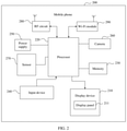
- FIG. 2 is a schematic structural diagram of a mobile phone according to an embodiment of this application.
- FIG. 3 is a schematic diagram of a face image detection method according to an embodiment of this application.
- FIG. 4 is a first schematic diagram of a pixel selection manner according to an embodiment of this application.
- FIG. 5 is a second schematic diagram of a pixel selection manner according to an embodiment of this application.
- FIG. 6 is a schematic diagram of a generated gradient change curve according to an embodiment of this application.
- FIG. 7 is a schematic diagram of a face image detection effect according to an embodiment of this application.
- FIG. 8 is a schematic diagram of a face image detection apparatus according to an embodiment of this application.
- FIG. 9 is a schematic structural diagram of a terminal device according to an embodiment of this application.
- a main process in which a user performs skin detection by using a face image is as follows: The user uses a front-facing camera or a rear-facing camera of a mobile phone to capture a face of the user at a short distance. In principle, only the user is in a picture. There is a curve on a screen of the mobile phone. The user needs to clamp cheeks near the curve to ensure that a size and a location of the face are basically fixed. Then, a face detection program outputs a final skin detection result.
- factors that affect the skin detection result mainly include: whether the user wears glasses, a lighting condition, whether focus is clear, and whether skin is blocked by hair. If the user wears glasses, skin in an eye region is blocked, and therefore the skin detection result is severely affected. According to an actual observation, if the user wears sunglasses, the user proactively takes off the sunglasses to perform skin detection. However, if the user often wears nearsighted glasses in daily life, the user does not proactively take off the glasses to perform skin detection. In this case, a terminal needs to prompt the user to take off the glasses when detecting that the user currently wears the glasses.
- the embodiments of this application provide a face image detection method.
- the method is applicable to a terminal device with a face image recognition function.
- facial features of a face image are recognized, and then a local image region between two eyes is determined.
- a frame structure of glasses usually includes main parts such as a lens rim, a bridge, a nose pad, an endpiece, and a temple. Because the bridge is connected to left and right lens rims, the bridge definitely affects a grayscale of the local image region, and a gradient value of a pixel reflects a change of the grayscale. Therefore, it may be determined, by analyzing a gradient value change rule of the image region, whether glasses are worn on the face image.
- the terminal device with the face image recognition function in the embodiments of this application may also be referred to as user equipment (User Equipment, UE), and is a device that may be installed with various communication applications or has a communication function, for example, a smartphone, a tablet, all kinds of wearable devices, a vehicle-mounted device, or a computer.
- UE user equipment
- the face image detection method provided in the embodiments of this application is applicable to a mobile phone shown in FIG. 2 .
- FIG. 2 is a schematic diagram of a hardware structure of a mobile phone applied to an embodiment of this application.
- a mobile phone 200 includes a display device 210 , a processor 220 , and a memory 230 .
- the memory 230 may be configured to store a software program and data, and the processor 220 runs the software program and the data that are stored in the memory 230 , to execute various function applications of the mobile phone 200 and perform data processing.
- the memory 230 may mainly include a program storage area and a data storage area.
- the program storage area may store an operating system, an application program required by at least one function (such as an image collecting function), or the like.
- the data storage area may store data (such as audio data, a phone book, or image data) that is created based on use of the mobile phone 200 , or the like.
- the memory 230 may include a high-speed random access memory, and may further include a nonvolatile memory, for example, at least one magnetic disk storage device, a flash memory device, or another volatile solid-state storage device.
- the processor 220 is a control center of the mobile phone 200 , and is connected to all parts of the entire mobile phone through various interfaces and lines. The processor 220 runs or executes the software program and/or the data that are/is stored in the memory 230 , to perform various functions of the mobile phone 200 and perform data processing, thereby performing overall monitoring on the mobile phone.
- the processor 220 may include one or more general-purpose processors, and may further include one or more DSPs (digital signal processor, digital signal processor), or may include one or more ISPs (image signal processor, image signal processor), and is configured to perform related operations, to implement the technical solution provided in this embodiment of this application.
- DSPs digital signal processor, digital signal processor
- ISPs image signal processor, image signal processor
- the mobile phone 200 further includes a camera 260 for capturing an image or a video.
- the camera 260 may be an ordinary camera, or may be a focusing camera.
- the mobile phone 200 may further include an input device 240 , configured to receive digital information, character information, or a contact touch operation/non-contact gesture that is input, and generate signal input that is related to user settings and function control of the mobile phone 200 , and the like.
- an input device 240 configured to receive digital information, character information, or a contact touch operation/non-contact gesture that is input, and generate signal input that is related to user settings and function control of the mobile phone 200 , and the like.
- the display panel 211 included in the display device 210 is configured to display information entered by a user or information provided for a user, and various menu interfaces of the mobile phone 200 , and the like, and is mainly configured to display a to-be-detected image obtained by the camera or a sensor in the mobile phone 200 in this embodiment of this application.
- the display panel 211 may be configured by using a liquid crystal display (liquid crystal display, LCD), an OLED (organic light-emitting diode, organic light-emitting diode), or the like.
- the mobile phone 200 may include a power supply 250 , configured to supply power to another module.
- the mobile phone 200 may further include one or more sensors 270 , such as an image sensor, an infrared sensor, and a laser sensor.
- the mobile phone 200 may further include a radio frequency (radio frequency, RF) circuit 280 , configured to perform network communication with a wireless network device, and may further include a Wi-Fi module 290 , configured to perform Wi-Fi communication with another device to obtain an image or data or the like transmitted by the another device.
- RF radio frequency
- the embodiments of this application provide a face image detection method and a terminal device, to accurately detect whether glasses are worn on a face image.
- the method and the terminal device in this application are based on a same inventive concept. Because problem-resolving principles of the method and the terminal device are similar, mutual reference may be made to implementation of the terminal device and the method. No repeated description is provided.
- a specific procedure of the method may include the following steps.
- Step 101 A processor of a mobile phone obtains a face image. Specifically, there are a plurality of methods for obtaining a face image.
- the processor may obtain, according to a user instruction, a picture specified by a user from an album folder stored in a memory of the mobile phone, and uses the picture as an obtained face image, or obtain a face image from a picture file sent by another terminal device, or may turn on a camera after receiving a camera turn-on instruction triggered by the user, and then the processor obtains a face avatar captured by the camera.
- Step 102 The processor of the mobile phone detects facial features of the face image, determines locations of two eyes on the face image, and finds locations of pupil centers of the two eyes.
- a specific detection method is a common face feature detection manner, and details are not described herein.
- Step 103 The processor may connect the two pupil centers by using a straight line, and may obtain a straight line segment whose endpoints are the two pupil centers, as shown in FIG. 4 .
- a line such as a curve may be alternatively used to connect the two pupil centers to obtain a line segment of another shape. Then, a center point P of the obtained line segment is located by taking a midpoint.
- Step 104 The processor of the mobile phone determines a local image region including the center point P.
- a square region between two inner canthi may be selected as a local image region.
- an upper side of the square region is taken below eyebrows, and a lower side of the square region is taken above nose pads.
- a region of another shape for example, a rectangular region or a trapezoid region, may be alternatively selected as a local image region. This is not limited in this embodiment of the present invention.
- Step 105 The processor of the mobile phone selects K columns of pixels from the local image region, calculates a gradient value of each pixel in each column of pixels, and generates K gradient vectors, where the gradient value may be a difference between a pixel value of a current pixel and a pixel value of an adjacent pixel in a same column of pixels.
- three columns of pixels may be selected from the local image region.
- the first column of pixels are pixels on a perpendicular bisector passing through the center point P, and the other two columns of pixels are pixels on tracks that are parallel to the perpendicular bisector and that have a same length as the perpendicular bisector.
- a method for selecting three columns of pixels shown in FIG. 5 may be used. Tracks separately formed by the three columns of pixels may be straight line segments, and certainly may be alternatively line segments of another shape.
- the straight line segments may not be parallel to each other, but all pixels in each column of pixels need to be sequentially arranged in a same direction, so that gradient values of the pixels can accurately reflect image grayscale changes at different locations.
- a reason for selecting three columns of pixels is that a perpendicular bisector of a connection line of two eyes may not be exactly located in a center of a bridge, and may not be drawn to the bridge of glasses. Therefore, several lines are separately drawn on left and right sides of the perpendicular bisector to ensure that at least one line can be drawn to the bridge of the glasses, thereby ensuring accuracy of gradient calculation.
- five columns of pixels, seven columns of pixels, or the like may be alternatively selected, that is, it is ensured that one column of pixels are pixels on the perpendicular bisector passing through the center point P, and other columns of pixels are columns of pixels that are parallel to the perpendicular bisector.
- Step 106 The processor of the mobile phone determines a result of comparing the K gradient vectors with a specified threshold. There are a plurality of comparison manners. For example, the K gradient vectors may be superposed to obtain a total gradient vector and then the total gradient vector is compared with a first threshold, or each gradient vector may be compared with a second threshold. Details are as follows:
- N pixels in the any column of pixels are consecutively numbered in a same direction (the direction may be from top to bottom, that is, from the forehead to the nose, and certainly there may be another direction, provided that orientations of each column of pixels are consistent) based on a location relationship between pixels.
- the three pixels in the first column of pixels there are three pixels in the first column of pixels, and the three pixels are identified as a pixel 1, a pixel 2, and a pixel 3 from bottom to top.
- there are also three pixels in the second column of pixels and the three pixels are identified as a pixel 1, a pixel 2, and a pixel 3 from bottom to top.
- There are also three pixels in the third column of pixels and the three pixels are identified as a pixel 1, a pixel 2, and a pixel 3 from bottom to top.
- N pixels in the any column of pixels are consecutively numbered in a same direction (the direction may be from top to bottom, that is, from the forehead to the nose, and certainly there may be another direction, provided that orientations of each column of pixels are consistent) based on a location relationship between pixels. For example, there are three pixels in the first column of pixels, and the three pixels are identified as a pixel 1, a pixel 2, and a pixel 3 from bottom to top. Likewise, there are also three pixels in the second column of pixels, and the three pixels are identified as a pixel 1, a pixel 2, and a pixel 3 from bottom to top. There are also three pixels in the third column of pixels, and the three pixels are identified as a pixel 1, a pixel 2, and a pixel 3 from bottom to top.
- Absolute values of N gradient values in gradient vectors corresponding to each column of pixels are separately taken. For example, absolute values are separately taken for gradient vectors separately corresponding to the pixel 1, the pixel 2, and the pixel 3 included in the first column of pixels, absolute values are separately taken for gradient vectors separately corresponding to the pixel 1, the pixel 2, and the pixel 3 included in the second column of pixels, and absolute values are separately taken for gradient vectors separately corresponding to the pixel 1, the pixel 2, and the pixel 3 included in the third column of pixels.
- Step 107 The processor of the mobile phone may output a display instruction to a display when determining that glasses are worn on the face image, where the display instruction may indicate that face image detection fails, and the user is required to take off the glasses and step 101 is performed again.
- Step 108 The processor of the mobile phone starts a subsequent skin detection procedure when determining that no glasses are worn on the face image.
- a specific process of glasses detection for the face image may be further divided into the following steps.
- k y ⁇ 2 - y ⁇ 1 x ⁇ 2 - x ⁇ 1
- ⁇ ⁇ b x ⁇ 2 ⁇ y ⁇ 1 - y ⁇ 2 ⁇ x ⁇ 1 x ⁇ 2 - x ⁇ 1 .
- Step b Calculate a location P (x0, y0) of a center point P of a connection line of the two eyes, where
- x ⁇ 0 x ⁇ 1 + x ⁇ 2 2
- ⁇ ⁇ y ⁇ ⁇ 0 y ⁇ 1 + y ⁇ 2 2 .
- (x1, y1) and (x2, y2) may be alternatively coordinates of two inner canthi or outer canthi.
- Step c Determine a perpendicular bisector of a midpoint of the connection line, and then determine pixels on the perpendicular bisector. That is, a track formed by the pixels is a straight line segment that passes through the center point P of the connection line and whose slope is ⁇ 1/k. A maximum length of an upper part of the straight line segment is 0.4 eye_r above a location of the center point P, and a maximum length of a lower part of the line segment is 0.2 eye_r below the location of the center point P.
- the perpendicular bisector is represented by
- Pixels on the other two straight line segments that are parallel to the perpendicular bisector and that have a same length as the perpendicular bisector are separately selected on left and right sides of the location of the center point P.
- Step d Calculate three gradient vectors.
- n pixels on each line segment are sequentially numbered from top to bottom, for example, (a1, b1), (a2, b2), . . . , and (an, bn), where n is a quantity of pixels, and a and b respectively represent row and column coordinate locations of a point on the image.
- RGB values of pixels at n locations are (r1, g1, b1), (r2, g2, b2), . . . , and (rn, gn, bn).
- a gradient value of a pixel on each line segment is calculated based on n RGB values.
- (r i ,g i ,b i ) is an RGB value of the i th pixel
- (r i-1 ,g i-1 ,b i-1 ) is an RGB value of the (i ⁇ 1) th pixel
- G i is an obtained gradient value of the i th pixel
- i is any one of N pixels.
- a principle of calculating a gradient in Formula [1] is: a gradient is calculated for an image, which is usually an operation on a grayscale image or a color image.
- a digital image is a discrete point-value spectrum, which may also be referred to as a two-dimensional discrete function.
- the gradient for the image is a derivative of the two-dimensional discrete function.
- a derivative for the image is a difference between two adjacent pixels in a horizontal or vertical direction.
- I is a value (for example, an RGB value) of a pixel on the image, and (i,j) is coordinates of the pixel.
- n pixels on each of the first column of pixels, the second column of pixels, and the third column of pixels there are n pixels on each of the first column of pixels, the second column of pixels, and the third column of pixels, and the n pixels in each column are sequentially numbered from top to bottom.
- coordinates of the first column of pixels are (a1, b1), (a2, b2), . . . , and (an, bn)
- coordinates of the second column of pixels are (a1′, b1′), (a2′, b2′), . . . , and (an′, bn′)
- coordinates of the third column pixels are (a1′′, b1′′), (a2′′, b2′′), . . . , and (an′′, bn′′).
- n is a quantity of pixels, and a and b respectively represent row and column coordinate locations of a pixel on the image.
- a gradient vector including gradient values of the first column of pixels is (G 2 , G 3 , . . . , G i , . . . , and G n );
- a gradient vector including gradient values of the second column of pixels is (G 2′ , G 3′ , . . . , G i′ , . . . , and G n′ );
- a gradient vector including gradient values of the third column of pixels is (G 2′′ , G 3′′ , . . . , G i′′ , . . .
- Step e Analyze a line graph shown in FIG. 6 .
- An analysis strategy may be: searching for a peak value from left to right of the line graph. For example, a gradient line graph is searched along a horizontal axis from left to right for a first gradient location corresponding to a gradient value greater than k times a median value of all gradients, and the gradient location is used as a left peak value; and then the gradient line graph is searched from right to left for a first gradient location corresponding to a gradient value greater than k times the median value of all the gradients, and the gradient location is used as a right peak value. If it is determined that a peak value meets any one of the following conditions, it may be determined that glasses are worn on the face image.
- Condition 1 There are two peak values in the line graph. A left peak value is greater than the first threshold.
- the first threshold is a gradient value 1000
- a right peak value is greater than the second threshold.
- the second threshold is a gradient value 600.
- a peak value appears on each of an upper edge and a lower edge. In this case, the condition 1 is usually met.
- Condition 2 There is one peak value in the line graph.
- the peak value is greater than the first threshold, s( ⁇ t) (for example, 5) gradient values in consecutive t (for example, 10) points on the right side of the line graph are less than a third threshold (for example, the third threshold is 20), and a gradient value of a left peak is k times greater than a gradient average value of locations ⁇ t to ⁇ s on the left side of the left peak.
- s( ⁇ t) for example, 5
- a third threshold for example, the third threshold is 20
- a gradient value of a left peak is k times greater than a gradient average value of locations ⁇ t to ⁇ s on the left side of the left peak.
- the condition 2 is usually met.
- a gradient value change line graph of each gradient vector is generated.
- a horizontal axis represents a number of a pixel
- a vertical axis represents an absolute value of a gradient value. If glasses are worn on the face image, in a normal case, gradient values of a same row of pixels in three gradient value change line graphs may change abruptly. If only one or two pixels in pixels with a same number are greater than the second threshold, and a pixel in another line graph is far less than the second threshold, it indicates that there may be a black mole or a headdress on the face, and therefore it is determined that no glasses are worn on the face image.
- the three columns of pixels are pixels above or below a bridge of a glasses frame. Because the bridge may be at an upper location, and the bridge is usually not lowered due to load-bearing on the bridge, there are more pixels above the bridge in the three columns of pixels. If the bridge is relatively wide, there are two obvious gradients in the line graph, as shown in FIG. 6 . If the bridge is relatively narrow, there is only one obvious gradient. If no glasses are worn, there is no obvious gradient.
- a transparent glasses frame can be effectively recognized in this method.
- transparent means that there is always a medium such as transparent plastic, an edge of the transparent glasses frame can always be viewed at some angles unless there is a very vertical angle.
- the transparent glasses frame has a color similar to a skin color in a middle region, but a gradient value in an edge region is obviously different from that in another region due to illumination. Therefore, two obvious gradient peaks (corresponding to upper and lower edges of the glasses frame) appear in a gradient graph, as shown in FIG. 6 .
- FIG. 7 it is learned from a test result shown in FIG. 7 that in the method, a gradient change line graph with a peak value may be obviously obtained for a face image on which glasses are worn, and there is no obvious peak value in a gradient change line graph for a face image on which no grasses are worn.
- the terminal device 700 includes a recognition unit 701 , a determining unit 702 , and a processing unit 703 .
- the recognition unit 701 may be configured to recognize two pupil centers of a face image.
- the determining unit 702 may be configured to: connect the two pupil centers, and determine a center point of a line segment whose endpoints are the two pupil centers.
- the processing unit 703 may be configured to: determine, in the face image, a local image region including the center point, select K columns of pixels from the local image region, calculate a gradient value of each pixel in each column of pixels, and generate K gradient vectors, where each echelon vector includes gradient values of all pixels in a corresponding column of pixels, a track formed by all pixels included in each column of pixels intersects the line segment, at least one intersecting point is the center point or is close to the center point, and K is a positive integer greater than or equal to 1; and determine, based on a result of comparing the K gradient vectors with a specified threshold, whether glasses are worn on the face image.
- the processing unit 703 calculates a gradient value of each pixel in each column of pixels by using a formula [1]. Specifically, for any column of pixels in the K columns of pixels, N pixels in the any column of pixels are consecutively numbered in a same direction based on a location relationship between pixels, and a gradient value of the i th pixel in the any column of pixels is calculated according to the formula [1].
- the K gradient vectors may be superposed to obtain a total gradient vector and then the total gradient vector is compared with a first threshold, or each gradient vector may be compared with a second threshold.
- the processing unit 703 superposes the K gradient vectors to obtain the total gradient vector and then compares the total gradient vector with the first threshold.
- gradient values of K pixels with a same number in each column of pixels are added to obtain a total gradient vector including N gradient sums; then absolute values of the N gradient sums in the total gradient vector are separately taken, and smoothing processing is performed on the absolute values of the N gradient sums to obtain a gradient change line graph; and when it is determined that at least one peak value in the gradient change line graph is greater than a first threshold, it is determined that glasses are worn on the face image.
- the processing unit 703 compares each gradient vector with a second threshold. Specifically, first, absolute values of N gradient values in each of the K gradient vectors are separately taken; and then when absolute values of gradient values of pixels with a same number in the K gradient vectors are all greater than the second threshold, it may be directly determined that glasses are worn on the face image.
- pixels in a local image region in which a bridge in a face is located are collected for a gradient analysis, so that a gradient change line graph of the local image region can be reflected.
- a main basis principle is that because the bridge is connected to left and right lens rims, the bridge definitely affects a grayscale of the local image region, and a gradient value of a pixel reflects a change of the grayscale. Therefore, when a peak value appears, it may be determined, by analyzing a gradient value change rule of the image region, whether glasses are worn on the face image.
- unit division is an example and is merely logical function division. In actual implementation, another division manner may be used.
- Functional units in the embodiments of this application may be integrated into one processing unit, or each of the units may exist alone physically, or two or more units are integrated into one unit.
- the integrated unit may be implemented in a form of hardware, or may be implemented in a form of a software functional unit.
- the integrated unit When the integrated unit is implemented in the form of a software functional unit and sold or used as an independent product, the integrated unit may be stored in a computer readable storage medium. Based on such an understanding, the technical solutions of this application essentially, or the part contributing to the prior art, or all or some of the technical solutions may be implemented in the form of a software product.
- the computer software product is stored in a storage medium and includes several instructions for instructing a computer device (which may be a personal computer, a server, or a network device) or a processor (processor) to perform all or some of the steps of the method in the embodiments of this application.
- the foregoing storage medium includes: any medium that can store program code, such as a USB flash drive, a removable hard disk, a read-only memory (read-only memory, ROM), a random access memory (random access memory, RAM), a magnetic disk, or an optical disc.
- program code such as a USB flash drive, a removable hard disk, a read-only memory (read-only memory, ROM), a random access memory (random access memory, RAM), a magnetic disk, or an optical disc.
- an embodiment of this application further provides a terminal device, and the terminal device is configured to implement the face image detection method described in the embodiment in FIG. 3 .
- the device includes a processor 801 , a memory 802 , and a display 803 .
- the processor 801 may be a central processing unit (central processing unit, CPU), a digital processing unit, or the like.
- the memory 802 is configured to store a face image and a program instruction of an operating system.
- the display 803 is configured to display, on a human-computer interaction interface of an application program, a skin detection result or a prompt indicating that glasses are worn on the face image.
- a specific connection medium between the processor 801 and the memory 802 is not limited in this embodiment of this application.
- the memory 802 , the processor 801 , and the display 803 are connected through a bus 804 in FIG. 8 .
- the bus is indicated by using a thick line in FIG. 8 .
- a manner of connection between other components is merely an example for description, and imposes no limitation.
- the bus may be classified into an address bus, a data bus, a control bus, and the like. For ease of representation, only one thick line is used to represent the bus in FIG. 8 , but this does not mean that there is only one bus or only one type of bus.
- the memory 802 may be a volatile memory (volatile memory), such as a random access memory (random-access memory, RAM).
- the memory 802 may be a non-volatile memory (non-volatile memory), such as a read-only memory, a flash memory (flash memory), a hard disk drive (hard disk drive, HDD), or a solid-state drive (solid-state drive, SSD).
- the memory 802 is, but not limited to, any other medium that can be used to carry or store expected program code in a form of an instruction or a data structure and can be accessed by a computer.
- the memory 803 may be a combination of the foregoing memories.
- the processor 801 executes the program instruction in the memory 802 , to implement the face image detection method shown in FIG. 8 .
- the method includes: recognizing two pupil centers of a face image; connecting the two pupil centers, and determining a center point of a line segment whose endpoints are the two pupil centers; determining, in the face image, a local image region including the center point, selecting K columns of pixels from the local image region, calculating a gradient value of each pixel in each column of pixels, and generating K gradient vectors, where each echelon vector includes gradient values of all pixels in a corresponding column of pixels, a track formed by all pixels included in each column of pixels intersects the line segment, at least one intersecting point is the center point or is close to the center point, and K is a positive integer greater than or equal to i; and determining, based on a result of comparing the K gradient vectors with a specified threshold, whether glasses are worn on the face image.
- the processor 801 adds gradient values of K pixels with a same number in all columns of pixels to obtain a total gradient vector including N gradient sums; separately takes absolute values of the N gradient sums in the total gradient vector, and performs smoothing processing on the absolute values of the N gradient sums to obtain a gradient change line graph; and when it is determined that at least one peak value in the gradient change line graph is greater than a first threshold, determine that glasses are worn on the face image.
- the processor 801 compares each gradient vector with a second threshold. Specifically, first, absolute values of N gradient values in each of the K gradient vectors are separately taken; and then when absolute values of gradient values of pixels with a same number in the K gradient vectors are all greater than the second threshold, it is determined that glasses are worn on the face image.
- the processor 801 may select, but not limited to, three columns of pixels.
- the track formed by all the pixels included in each column of pixels is a straight line segment, the straight line segment vertically intersects the line segment whose endpoints are the two pupil centers, a straight line segment formed by all pixels included in one column of pixels is a perpendicular bisector, and a straight line segment formed by all pixels included in each of remaining (K ⁇ 1) columns of pixels is a line segment that is parallel to the perpendicular bisector and that has a same length as the perpendicular bisector.
- An embodiment of this application further provides a computer readable storage medium, configured to store a computer software instruction that needs to be executed by the foregoing processor.
- the computer software instruction includes a program that needs to be executed by the foregoing processor.
- An embodiment of this application further provides a computer program product.
- the computer program product is executed by a computer, the computer is enabled to perform the foregoing face image detection method.
- the embodiments of this application provide a face image detection method and apparatus, and a terminal device.
- a processor of the terminal device obtains a face image, and determines a local image region in which a bridge is located. Because the image region is affected by the bridge, a grayscale of the local image region varies greatly at a location of the bridge. Therefore, it may be determined, by analyzing a gradient value change rule of the local image region, whether glasses are worn on the face image. If gradient values of some pixels are obviously larger, it is likely that the pixels are pixels near the bridge, and therefore it may be determined that glasses are worn on the face image. Otherwise, it may be determined that no glasses are worn on the face image.
- the various illustrative logical blocks, modules, and circuits described in the embodiments of this application may implement or operate the described functions by using a general processing unit, a digital signal processing unit, an application-specific integrated circuit (ASIC), a field programmable gate array (FPGA) or another programmable logical apparatus, a discrete gate or transistor logic, a discrete hardware component, or a design of any combination thereof.
- the general processing unit may be a microprocessing unit.
- the general processing unit may be any traditional processing unit, controller, microcontroller, or state machine.
- the processing unit may be implemented by a combination of computing apparatuses, such as a digital signal processing unit and a microprocessing unit, a plurality of microprocessing units, one or more microprocessing units with a digital signal processing unit core, or any other similar configuration.
- Steps of the methods or algorithms described in the embodiments of this application may be directly embedded into hardware, a software module executed by a processing unit, or a combination thereof.
- the software module may be stored in a RAM memory, a flash memory, a ROM memory, an EPROM memory, an EEPROM memory, a register, a hard disk, a removable magnetic disk, a CD-ROM, or a storage medium of any other form in the art.
- the storage medium may be connected to a processing unit so that the processing unit may read information from the storage medium and write information to the storage medium.
- the storage medium may be alternatively integrated into a processing unit.
- the processing unit and the storage medium may be arranged in an ASIC, and the ASIC may be arranged in a user terminal.
- the processing unit and the storage medium may be alternatively arranged in different components of the user terminal.
- the functions described in the embodiments of this application may be implemented by using hardware, software, firmware, or any combination thereof. If the present invention is implemented by software, these functions may be stored in a computer readable medium or are transmitted to the computer readable medium in a form of one or more instructions or code.
- the computer readable medium is either a computer storage medium or a communications medium that enables a computer program to move from one place to another.
- the storage medium may be an available medium that may be accessed by any general or special computer.
- such a computer readable medium may include but is not limited to a RAM, a ROM, an EEPROM, a CD-ROM, or another optical disc storage, a disk storage or another magnetic storage apparatus, or any other medium that may be used to bear or store program code, where the program code is in a form of an instruction or a data structure or in a form that can be read by a general or special computer or a general or special processing unit.
- any connection may be appropriately defined as a computer readable medium.
- the software is included in a defined computer readable medium.
- the disc (disk) and the disk (disc) include a compressed disk, a laser disk, an optical disc, a DVD, a floppy disk, and a Blu-ray disc.
- the disk generally copies data by a magnetic means, and the disc generally copies data optically by a laser means.
- the foregoing combination may also be included in the computer readable medium.
Abstract
Description
G i =r i −r i-1 +g i −g i-1 +b i −b i-1
G i =r i −r i-1 +g i −g i-1 +b i −b i-1 Formula [1]
Claims (15)
G i =r i −r i-1 +g i −g i-1 +b i −b i-1, wherein
G i =r i −r i-1 +g i −g i-1 +b i −b i-1, wherein
G i =r i −r i-1 +g i −g i-1 +b i −b i-1, wherein
Applications Claiming Priority (1)
| Application Number | Priority Date | Filing Date | Title |
|---|---|---|---|
| PCT/CN2017/110951 WO2019095117A1 (en) | 2017-11-14 | 2017-11-14 | Facial image detection method and terminal device |
Publications (2)
| Publication Number | Publication Date |
|---|---|
| US20210365672A1 US20210365672A1 (en) | 2021-11-25 |
| US11270100B2 true US11270100B2 (en) | 2022-03-08 |
Family
ID=66538363
Family Applications (1)
| Application Number | Title | Priority Date | Filing Date |
|---|---|---|---|
| US16/763,889 Active 2038-02-14 US11270100B2 (en) | 2017-11-14 | 2017-11-14 | Face image detection method and terminal device |
Country Status (4)
| Country | Link |
|---|---|
| US (1) | US11270100B2 (en) |
| EP (1) | EP3699808B1 (en) |
| CN (1) | CN110313006B (en) |
| WO (1) | WO2019095117A1 (en) |
Families Citing this family (5)
| Publication number | Priority date | Publication date | Assignee | Title |
|---|---|---|---|---|
| WO2020129138A1 (en) * | 2018-12-18 | 2020-06-25 | 日本電気株式会社 | Image processing device, image processing method, and storage medium |
| CN112733570A (en) * | 2019-10-14 | 2021-04-30 | 北京眼神智能科技有限公司 | Glasses detection method and device, electronic equipment and storage medium |
| CN112651322A (en) * | 2020-12-22 | 2021-04-13 | 北京眼神智能科技有限公司 | Cheek shielding detection method and device and electronic equipment |
| CN112826483B (en) * | 2021-01-08 | 2022-03-08 | 中国科学院自动化研究所 | Fingertip video-based heart rate detection method, system and device |
| CN112862848B (en) * | 2021-03-18 | 2023-11-21 | 北京小米移动软件有限公司 | Image processing method, device and storage medium |
Citations (23)
| Publication number | Priority date | Publication date | Assignee | Title |
|---|---|---|---|---|
| CN1606029A (en) | 2004-11-04 | 2005-04-13 | 上海交通大学 | Infrared human face spectacle disturbance elimination method based on regional characteristic element compensation |
| WO2007062478A1 (en) | 2005-11-30 | 2007-06-07 | Seeing Machines Pty Ltd | Visual tracking of eye glasses in visual head and eye tracking systems |
| US20070177794A1 (en) | 2006-01-31 | 2007-08-02 | Fuji Photo Film Co., Ltd. | Method and apparatus for automatic eyeglasses detection using a nose ridge mask |
| CN101908152A (en) | 2010-06-11 | 2010-12-08 | 电子科技大学 | Customization classifier-based eye state identification method |
| CN102163288A (en) | 2011-04-06 | 2011-08-24 | 北京中星微电子有限公司 | Eyeglass detection method and device |
| CN103020579A (en) | 2011-09-22 | 2013-04-03 | 上海银晨智能识别科技有限公司 | Face recognition method and system, and removing method and device for glasses frame in face image |
| CN103093215A (en) | 2013-02-01 | 2013-05-08 | 北京天诚盛业科技有限公司 | Eye location method and device |
| CN103902962A (en) | 2012-12-28 | 2014-07-02 | 汉王科技股份有限公司 | Shielding or light source self-adaption human face recognition method and device |
| CN104408426A (en) | 2014-11-27 | 2015-03-11 | 小米科技有限责任公司 | Method and device for removing glasses in face image |
| CN104463128A (en) | 2014-12-17 | 2015-03-25 | 智慧眼(湖南)科技发展有限公司 | Glass detection method and system for face recognition |
| US20150243015A1 (en) | 2012-09-07 | 2015-08-27 | Tipheret | Method and device for preparing a spectacle frame |
| CN105335695A (en) | 2015-08-19 | 2016-02-17 | 华南理工大学 | Glasses detection based eye positioning method |
| CN105404877A (en) | 2015-12-08 | 2016-03-16 | 商汤集团有限公司 | Human face attribute prediction method and apparatus based on deep study and multi-task study |
| CN106067016A (en) | 2016-07-20 | 2016-11-02 | 深圳市飘飘宝贝有限公司 | A kind of facial image eyeglass detection method and device |
| CN106200925A (en) | 2016-06-28 | 2016-12-07 | 广东欧珀移动通信有限公司 | The control method of mobile terminal, device and mobile terminal |
| CN106326828A (en) | 2015-11-08 | 2017-01-11 | 北京巴塔科技有限公司 | Eye positioning method applied to face recognition |
| CN106407911A (en) | 2016-08-31 | 2017-02-15 | 乐视控股(北京)有限公司 | Image-based eyeglass recognition method and device |
| CN106503611A (en) | 2016-09-09 | 2017-03-15 | 西安理工大学 | Facial image eyeglass detection method based on marginal information projective iteration mirror holder crossbeam |
| US20170076142A1 (en) * | 2015-09-15 | 2017-03-16 | Google Inc. | Feature detection and masking in images based on color distributions |
| US20170116736A1 (en) * | 2015-10-23 | 2017-04-27 | Fujitsu Limited | Line of sight detection system and method |
| US20170119248A1 (en) * | 2014-06-20 | 2017-05-04 | Sdip Holdings Pty Ltd | Monitoring drowsiness |
| CN106778453A (en) | 2015-11-25 | 2017-05-31 | 腾讯科技(深圳)有限公司 | The method and device of eyeglasses-wearing is detected in facial image |
| CN106778451A (en) | 2015-11-20 | 2017-05-31 | 懒虫(天津)科技有限公司 | A kind of eyeglass detection method of face recognition |
-
2017
- 2017-11-14 EP EP17932491.8A patent/EP3699808B1/en active Active
- 2017-11-14 WO PCT/CN2017/110951 patent/WO2019095117A1/en unknown
- 2017-11-14 US US16/763,889 patent/US11270100B2/en active Active
- 2017-11-14 CN CN201780086806.9A patent/CN110313006B/en active Active
Patent Citations (25)
| Publication number | Priority date | Publication date | Assignee | Title |
|---|---|---|---|---|
| CN1606029A (en) | 2004-11-04 | 2005-04-13 | 上海交通大学 | Infrared human face spectacle disturbance elimination method based on regional characteristic element compensation |
| WO2007062478A1 (en) | 2005-11-30 | 2007-06-07 | Seeing Machines Pty Ltd | Visual tracking of eye glasses in visual head and eye tracking systems |
| US20070177794A1 (en) | 2006-01-31 | 2007-08-02 | Fuji Photo Film Co., Ltd. | Method and apparatus for automatic eyeglasses detection using a nose ridge mask |
| CN101908152A (en) | 2010-06-11 | 2010-12-08 | 电子科技大学 | Customization classifier-based eye state identification method |
| CN102163288A (en) | 2011-04-06 | 2011-08-24 | 北京中星微电子有限公司 | Eyeglass detection method and device |
| CN103020579A (en) | 2011-09-22 | 2013-04-03 | 上海银晨智能识别科技有限公司 | Face recognition method and system, and removing method and device for glasses frame in face image |
| US20150243015A1 (en) | 2012-09-07 | 2015-08-27 | Tipheret | Method and device for preparing a spectacle frame |
| CN103902962A (en) | 2012-12-28 | 2014-07-02 | 汉王科技股份有限公司 | Shielding or light source self-adaption human face recognition method and device |
| CN103093215A (en) | 2013-02-01 | 2013-05-08 | 北京天诚盛业科技有限公司 | Eye location method and device |
| US20170119248A1 (en) * | 2014-06-20 | 2017-05-04 | Sdip Holdings Pty Ltd | Monitoring drowsiness |
| CN104408426A (en) | 2014-11-27 | 2015-03-11 | 小米科技有限责任公司 | Method and device for removing glasses in face image |
| CN104463128A (en) | 2014-12-17 | 2015-03-25 | 智慧眼(湖南)科技发展有限公司 | Glass detection method and system for face recognition |
| CN105335695A (en) | 2015-08-19 | 2016-02-17 | 华南理工大学 | Glasses detection based eye positioning method |
| US20170076142A1 (en) * | 2015-09-15 | 2017-03-16 | Google Inc. | Feature detection and masking in images based on color distributions |
| US20170116736A1 (en) * | 2015-10-23 | 2017-04-27 | Fujitsu Limited | Line of sight detection system and method |
| CN106326828A (en) | 2015-11-08 | 2017-01-11 | 北京巴塔科技有限公司 | Eye positioning method applied to face recognition |
| CN106778451A (en) | 2015-11-20 | 2017-05-31 | 懒虫(天津)科技有限公司 | A kind of eyeglass detection method of face recognition |
| CN106778453A (en) | 2015-11-25 | 2017-05-31 | 腾讯科技(深圳)有限公司 | The method and device of eyeglasses-wearing is detected in facial image |
| WO2017088804A1 (en) | 2015-11-25 | 2017-06-01 | 腾讯科技(深圳)有限公司 | Method and apparatus for detecting wearing of spectacles in facial image |
| US20170364738A1 (en) | 2015-11-25 | 2017-12-21 | Tencent Technology (Shenzhen) Company Limited | Method and apparatus for detecting glasses in a face image |
| CN105404877A (en) | 2015-12-08 | 2016-03-16 | 商汤集团有限公司 | Human face attribute prediction method and apparatus based on deep study and multi-task study |
| CN106200925A (en) | 2016-06-28 | 2016-12-07 | 广东欧珀移动通信有限公司 | The control method of mobile terminal, device and mobile terminal |
| CN106067016A (en) | 2016-07-20 | 2016-11-02 | 深圳市飘飘宝贝有限公司 | A kind of facial image eyeglass detection method and device |
| CN106407911A (en) | 2016-08-31 | 2017-02-15 | 乐视控股(北京)有限公司 | Image-based eyeglass recognition method and device |
| CN106503611A (en) | 2016-09-09 | 2017-03-15 | 西安理工大学 | Facial image eyeglass detection method based on marginal information projective iteration mirror holder crossbeam |
Non-Patent Citations (3)
| Title |
|---|
| Gang, R. et al., "Glasses detection based on the edge information of face pictures", Software Guide, vol. 13 No.7, Jul. 2014, 3 pages. (With an English Abstract). |
| Jiang, X. et al., "Towards Detection of Glasses in Facial Images", Fourteenth International Conference on Pattern Recognition (Cat. No. 98EX170), Aug. 6, 2002, 10 pages. |
| Mohammad, A. S. et al., "Eyeglasses Detection based on Learning and Non-learning based Classification Schemes", 2017 IEEE International Symposium on Technologies for Homeland Security (HST), Jun. 8, 2017, 5 pages. |
Also Published As
| Publication number | Publication date |
|---|---|
| EP3699808A1 (en) | 2020-08-26 |
| US20210365672A1 (en) | 2021-11-25 |
| CN110313006B (en) | 2021-12-14 |
| WO2019095117A1 (en) | 2019-05-23 |
| EP3699808B1 (en) | 2023-10-25 |
| CN110313006A (en) | 2019-10-08 |
| EP3699808A4 (en) | 2020-11-18 |
Similar Documents
| Publication | Publication Date | Title |
|---|---|---|
| US11270100B2 (en) | Face image detection method and terminal device | |
| KR100947990B1 (en) | Gaze Tracking Apparatus and Method using Difference Image Entropy | |
| US10740912B2 (en) | Detection of humans in images using depth information | |
| US11612314B2 (en) | Electronic device and method for determining degree of conjunctival hyperemia by using same | |
| US10395094B2 (en) | Method and apparatus for detecting glasses in a face image | |
| US20150110364A1 (en) | Image processing device and image processing method | |
| US9508004B2 (en) | Eye gaze detection apparatus, computer-readable recording medium storing eye gaze detection program and eye gaze detection method | |
| CN108351961A (en) | Image and characteristic mass merge ocular angiogenesis and face and/or sub- facial information for the image enhancement and feature extraction of ocular angiogenesis and face recognition and for biological recognition system | |
| US10254831B2 (en) | System and method for detecting a gaze of a viewer | |
| KR20200118076A (en) | Biometric detection method and device, electronic device and storage medium | |
| US9501691B2 (en) | Method and apparatus for detecting blink | |
| EP4095744A1 (en) | Automatic iris capturing method and apparatus, computer-readable storage medium, and computer device | |
| WO2019061659A1 (en) | Method and device for removing eyeglasses from facial image, and storage medium | |
| JP6956986B1 (en) | Judgment method, judgment device, and judgment program | |
| CN111259757B (en) | Living body identification method, device and equipment based on image | |
| US20230020578A1 (en) | Systems and methods for vision test and uses thereof | |
| JP6399122B2 (en) | Face detection apparatus and control method thereof | |
| CN106991360B (en) | Face identification method and face identification system | |
| CN114973344A (en) | Face detection method, face detection device, terminal equipment and computer readable storage medium | |
| KR101276792B1 (en) | Eye detecting device and method thereof | |
| KR101985658B1 (en) | Method and apparatus for obtaining fingerprint data in terminal | |
| NL2024816B1 (en) | Detection method for detecting an occlusion of an eye region in an image | |
| JP6295808B2 (en) | Eye detection device, eye detection method, and eye detection program | |
| JP6721169B1 (en) | Image processing method, image processing apparatus, and image processing program | |
| TWI514854B (en) | Establishment of Adjustable Block - based Background Model and Real - time Image Object Detection |
Legal Events
| Date | Code | Title | Description |
|---|---|---|---|
| FEPP | Fee payment procedure |
Free format text: ENTITY STATUS SET TO UNDISCOUNTED (ORIGINAL EVENT CODE: BIG.); ENTITY STATUS OF PATENT OWNER: LARGE ENTITY |
|
| AS | Assignment |
Owner name: HUAWEI TECHNOLOGIES CO., LTD., CHINA Free format text: ASSIGNMENT OF ASSIGNORS INTEREST;ASSIGNORS:HU, HONGWEI;DONG, CHEN;GAO, WENMEI;REEL/FRAME:052964/0625 Effective date: 20200616 |
|
| STPP | Information on status: patent application and granting procedure in general |
Free format text: NOTICE OF ALLOWANCE MAILED -- APPLICATION RECEIVED IN OFFICE OF PUBLICATIONS |
|
| STPP | Information on status: patent application and granting procedure in general |
Free format text: AWAITING TC RESP., ISSUE FEE NOT PAID |
|
| STPP | Information on status: patent application and granting procedure in general |
Free format text: NOTICE OF ALLOWANCE MAILED -- APPLICATION RECEIVED IN OFFICE OF PUBLICATIONS |
|
| STCF | Information on status: patent grant |
Free format text: PATENTED CASE |