US11269680B2 - Information processing apparatus, information processing system, and information processing method - Google Patents

Information processing apparatus, information processing system, and information processing method Download PDF

Info

Publication number
US11269680B2
US11269680B2 US16/860,155 US202016860155A US11269680B2 US 11269680 B2 US11269680 B2 US 11269680B2 US 202016860155 A US202016860155 A US 202016860155A US 11269680 B2 US11269680 B2 US 11269680B2
Authority
US
United States
Prior art keywords
information processing
log
processing apparatus
retained
image forming
Prior art date
Legal status (The legal status is an assumption and is not a legal conclusion. Google has not performed a legal analysis and makes no representation as to the accuracy of the status listed.)
Active, expires
Application number
US16/860,155
Other versions
US20200364079A1 (en
Inventor
Kohichiroh MINAMI
Current Assignee (The listed assignees may be inaccurate. Google has not performed a legal analysis and makes no representation or warranty as to the accuracy of the list.)
Ricoh Co Ltd
Original Assignee
Ricoh Co Ltd
Priority date (The priority date is an assumption and is not a legal conclusion. Google has not performed a legal analysis and makes no representation as to the accuracy of the date listed.)
Filing date
Publication date
Application filed by Ricoh Co Ltd filed Critical Ricoh Co Ltd
Assigned to RICOH COMPANY, LTD. reassignment RICOH COMPANY, LTD. ASSIGNMENT OF ASSIGNORS INTEREST (SEE DOCUMENT FOR DETAILS). Assignors: MINAMI, KOHICHIROH
Publication of US20200364079A1 publication Critical patent/US20200364079A1/en
Application granted granted Critical
Publication of US11269680B2 publication Critical patent/US11269680B2/en
Active legal-status Critical Current
Adjusted expiration legal-status Critical

Links

Images

Classifications

    • GPHYSICS
    • G06COMPUTING; CALCULATING OR COUNTING
    • G06FELECTRIC DIGITAL DATA PROCESSING
    • G06F9/00Arrangements for program control, e.g. control units
    • G06F9/06Arrangements for program control, e.g. control units using stored programs, i.e. using an internal store of processing equipment to receive or retain programs
    • G06F9/46Multiprogramming arrangements
    • G06F9/48Program initiating; Program switching, e.g. by interrupt
    • G06F9/4806Task transfer initiation or dispatching
    • G06F9/4843Task transfer initiation or dispatching by program, e.g. task dispatcher, supervisor, operating system
    • G06F9/485Task life-cycle, e.g. stopping, restarting, resuming execution

Definitions

  • the present application relates to an information processing apparatus, an information processing system, and an information processing method.
  • Example embodiments include an information processing apparatus, an information processing system, and an information processing method, each of which: stores in a memory a retained log which has not been transferred to an external device, among a plurality of logs generated in response to execution of a job; and stop operating the information processing apparatus and reactivate the information processing apparatus, based on a number of retained logs.
  • FIG. 1 is a diagram illustrating an exemplary configuration of an information processing system according to an embodiment of the present invention
  • FIG. 2 is a block diagram of an exemplary hardware configuration of an image forming apparatus according to the embodiment of the present invention
  • FIG. 3 is a block diagram of an exemplary hardware configuration of a log accumulation server according to the embodiment of the present invention.
  • FIG. 4 is a block diagram illustrating an exemplary functional configuration of an image forming apparatus according to a first embodiment
  • FIG. 5 is a sequence diagram illustrating a processing example by the image forming apparatus according to the first embodiment
  • FIG. 6 is a flowchart illustrating the processing example by the image forming apparatus according to the first embodiment
  • FIG. 7 is a block diagram illustrating an exemplary functional configuration of an image forming apparatus according to a second embodiment
  • FIG. 8 is a diagram illustrating an example of a notification screen for reactivating
  • FIG. 9 is a diagram illustrating an example of an input screen for log accumulation server information.
  • FIGS. 10A and 10B are a flowchart illustrating a processing example by the image forming apparatus according to the second embodiment.
  • a retained log which has not been transferred to an external device is stored, and the information processing apparatus is reactivated (i.e., rebooted) based on the number of the retained logs.
  • the information processing apparatus is reactivated (i.e., rebooted) based on the number of the retained logs.
  • FIG. 1 is a diagram for illustrating an exemplary configuration of an information processing system according to an embodiment of the present invention.
  • an information processing system 1 includes image forming apparatuses 2 and 3 , and a log accumulation server 4 .
  • the apparatuses 2 and 3 and the log accumulation server 4 are communicably connected to one another via a network 100 .
  • Each of the image forming apparatuses 2 and 3 is a multifunction peripheral, product, or printer (MFP) and has an image forming function such as copying, scanning, printing such as laser printing.
  • Each of the image forming apparatuses 2 and 3 includes means for wireless communication or means for wired communication.
  • FIG. 1 illustrates an example in which the information processing system 1 includes two image forming apparatuses 2 and 3 . However, the information processing system 1 may include a plurality of image forming apparatuses. Since the image forming apparatuses 2 and 3 may have the same structure and function, only the image forming apparatus 2 of the image forming apparatuses 2 and 3 will be described below.
  • a log corresponding to the executed job is generated.
  • the image forming apparatus 2 transfers the generated log to the log accumulation server 4 in which information such as an address is set in advance.
  • the log includes a device log and an image log.
  • the device log is a log which records a detailed job content such as a person who executes a job or execution time of the job, the number of printed sheets by the image forming apparatus 2 , and color or monochrome print.
  • the image log is a log which records image data and simple information as bibliographic information.
  • the image forming apparatus 2 stops or reactivates the operation of the image forming apparatus 2 based on the number of the retained logs.
  • the log accumulation server 4 as an example of an accumulation device is achieved by a computer in which a general operating system (OS) or the like is installed, and includes means for wireless communication or means for wired communication.
  • OS general operating system
  • the image forming apparatus 2 detects success or failure of the transfer. Based on the detection result, the image forming apparatus 2 stores the retained log, stops the operation of the image forming apparatus 2 , or reactivates the image forming apparatus 2 .
  • FIG. 2 is a block diagram illustrating an exemplary hardware configuration of the image forming apparatus 2 .
  • the image forming apparatus 2 includes a controller 910 , a short-range communication circuit 920 , an engine controller 930 , an operation panel 940 , and a network interface (I/F) 950 .
  • the controller 910 includes a central processing unit (CPU) 901 , a system memory (MEM-P) 902 , a north bridge (NB) 903 , a south bridge (SB) 904 , an application specific integrated circuit (ASIC) 906 , a local memory (MEM-C) 907 as a memory, a hard disk drive (HDD) controller 908 , and a hard disk (HD) 909 as a memory.
  • the NB 903 and the ASIC 906 are coupled to each other via an accelerated graphics port (AGP) bus 921 .
  • AGP accelerated graphics port
  • the CPU 901 is a controller that controls the entire image forming apparatus 2 .
  • the NB 903 is a bridge for coupling the CPU 901 with the MEM-P 902 , the SB 904 , and the AGP bus 921 .
  • the NB 903 includes a memory controller that controls reading from or writing to the MEM-P 902 , a peripheral component interconnect (PCI) master, and an AGP target.
  • PCI peripheral component interconnect
  • the MEM-P 902 includes a read only memory (ROM) 902 a , which is a memory for storing programs and data for realizing each function of the controller 910 , and a random access memory (RAM) 902 b used for decompressing programs and data, and as a drawing memory for memory printing.
  • ROM read only memory
  • RAM random access memory
  • the programs stored in the RAM 902 b may be provided by being recorded in a non-transitory computer-readable recording medium such as a compact disc (CD)-ROM, a CD-R, and a digital versatile disc (DVD) in a file in an installable format or an executable format.
  • a non-transitory computer-readable recording medium such as a compact disc (CD)-ROM, a CD-R, and a digital versatile disc (DVD) in a file in an installable format or an executable format.
  • the SB 904 is a bridge for coupling the NB 903 with a PCI device, and a peripheral device.
  • the ASIC 906 is an integrated circuit (IC) for image processing having hardware elements for image processing, and has a role of a bridge that couples the AGP bus 921 , the PCI bus 922 , the HDD controller 908 , and the MEM-C 907 , respectively.
  • the ASIC 906 includes a PCI target and an AGP master, an arbiter (ARB) that forms the core of the ASIC 906 , a memory controller that controls the MEM-C 907 , and a plurality of direct memory access controllers (DMACs) that rotate image data using hardware logic or the like, and a PCI unit for transferring data between the scanner 931 and the printer 932 via the PCI bus 922 .
  • AGP master an arbiter
  • ARB arbiter
  • DMACs direct memory access controllers
  • the ASIC 906 may be coupled by an interface such as a USB interface and an institute of electrical and electronics engineers (IEEE)1394.
  • IEEE institute of electrical and electronics engineers
  • the MEM-C 907 is a local memory used as an image buffer for copying and a code buffer.
  • the HD 909 is a storage for accumulating image data, font data used for printing, and a form.
  • the HDD controller 908 controls reading from or writing to the HDD controller 908 under the control of the CPU 901 .
  • the AGP bus 921 is a bus interface for a graphics accelerator card proposed to speed up graphic processing.
  • the AGP bus 921 can speed up the graphics accelerator card by directly accessing the MEM-P 902 at high throughput.
  • the short-range communication circuit 920 includes a short-range communication circuit 920 a .
  • the short-range communication circuit 920 is a communication circuit such as near field communication (NFC) and Bluetooth (registered trademark).
  • the engine controller 930 is implemented by the scanner 931 and the printer 932 .
  • the operation panel 940 includes a panel display 940 a such as a touch panel that displays current setting values, a selection screen, and the like, and that receives input from a person who operates the panel, and an operation panel 940 b including a numeric keypad for receiving set values for image forming conditions such as density setting conditions, a start key for receiving a copy start instruction, and the like.
  • the controller 910 controls the entire image forming apparatus 2 and controls, for example, drawing (rendering), communication, input from the operation panel 940 , and the like.
  • the scanner 931 or the printer 932 includes an image processing such as error diffusion and gamma conversion.
  • the image forming apparatus 2 can sequentially switch and select a document box function, a copy function, a printer function, and a facsimile function by using an application switching key on the operation panel 940 .
  • a document box mode is set when the document box function is selected, a copy mode is set when the copy function is selected, a printer mode is set when the printer function is selected, and a facsimile mode is set when the facsimile function is selected.
  • the network I/F 950 is an interface for performing data communication by using the network 100 .
  • the short-range communication circuit 920 and the network I/F 950 are electrically coupled to the ASIC 906 via the PCI bus 922 .
  • FIG. 3 is a block diagram illustrating an exemplary hardware configuration of the log accumulation server 4 .
  • the log accumulation server 4 is implemented by a computer.
  • the log accumulation server 4 includes a CPU 501 , a ROM 502 , a RAM 503 , an HD 504 , and an HDD controller 505 .
  • the log accumulation server 4 includes a display 506 , an external device connection I/F 508 , a network I/F 509 , a data bus 510 , a keyboard 511 , a pointing device 512 , a digital versatile disk rewritable (DVD-RW) drive 514 , and a media I/F 516 .
  • DVD-RW digital versatile disk rewritable
  • the CPU 501 controls the operation of the entire log accumulation server 4 .
  • the ROM 502 stores a program used for driving the CPU 501 , such as an initial program loader (IPL).
  • the RAM 503 is used as a work area for the CPU 501 .
  • the HD 504 stores various types of data such as a program.
  • the HDD controller 505 controls reading or writing of various data from or to the HD 504 in accordance with the control of the CPU 501 .
  • the display 506 displays various kinds of information such as a cursor, a menu, a window, a character, and an image.
  • the external device connection I/F 508 is an interface for coupling various external devices.
  • the external device is a universal serial bus (USB) memory, a printer, or the like.
  • the network I/F 509 is an interface for performing data communication by using the network 100 .
  • the data bus 510 may be an address bus, a data bus or the like for electrically connecting each component such as the CPU 501 .
  • the keyboard 511 is a type of input means having a plurality of keys for inputting a character, a numeric value, various instructions, and the like.
  • the pointing device 512 is a type of input means for selecting and executing various instructions, selecting a processing object, moving the cursor, and the like.
  • the DVD-RW drive 514 controls reading or writing of various data from or to a DVD-RW 513 as an example of a removable recording medium.
  • the removable recording medium is not limited to the DVD-RW, and may be a DVD-R and the like.
  • the media I/F 516 controls reading or writing (memory) of data from or to a recording medium 515 such as a flash memory.
  • FIG. 4 is a block diagram illustrating an exemplary functional configuration of the image forming apparatus 2 .
  • the image forming apparatus 2 includes a job execution device 21 , a log management device 22 , a log transfer device 23 , a log storage 24 , a retention abnormality history storage 25 , and an operation controller 26 .
  • the log storage 24 and the retention abnormality history storage 25 are achieved by a nonvolatile memory such as the HD 909 in FIG. 2 , and the job execution device 21 , the log management device 22 , the log transfer device 23 , and the operation controller 26 are achieved by executing a predetermined program by the CPU 901 in FIG. 2 .
  • the log management device 22 receives a log accumulation request from the job execution device 21 in response to job execution, generates a log related to the job, and transfers the generated log to the log accumulation server 4 via the log transfer device 23 .
  • the transferred log is stored in the log accumulation server 4 .
  • the log management device 22 stores the log which have failed to be transferred as a retained log in the log storage 24 , and counts the number of the retained logs.
  • the operation controller 26 When retention abnormality occurs in which the count number of the retained logs by the log management device 22 becomes equal to or more than a predetermined threshold value, the operation controller 26 receives a notification indicating the occurrence of the retention abnormality from the log management device 22 , stops the operation of the image forming apparatus 2 , and then reactivates the image forming apparatus 2 . After the operation controller 26 reactivates the image forming apparatus 2 , the retained logs stored in the log storage 24 are transferred to the log accumulation server 4 via the log transfer device 23 . When the transfer is successful, the image forming apparatus 2 releases to stop the operation, and restart the operation. The detailed function of each unit will be described below.
  • the log management device 22 includes a log generating device 221 , a transfer result receiver 222 , and a retention abnormality determination device 223 , and provides functions such as log generation, transfer instruction, and determination of log retention abnormality.
  • the log generating device 221 responds to a log accumulation request received from the job executor 21 to generate a log corresponding to the request. Then, the log generating device 221 outputs the generated log to the log transfer device 23 , and instructs a log transfer.
  • the log transfer device 23 transfers the log to the log accumulation server 4 in response to the log transfer instructed by the log generating device 221 .
  • the log transfer device 23 detects successful transfer or failed transfer to the log accumulation server 4 , and notifies the detection result to the transfer result receiver 222 .
  • the transfer result receiver 222 receives a notification indicating the successful transfer or failed transfer from the log transfer device 23 .
  • the transfer result receiver 222 outputs the log related to the failed transfer acquired from the log generating device 221 to the log storage 24 to store the log as a retained log, and notifies the retention abnormality determination device 223 of the failed transfer.
  • the transfer result receiver 222 After the count number of the retained logs becomes equal to or more than the predetermined threshold value, and the image forming apparatus 2 is reactivated, when the transfer of the retained logs stored in the log storage 24 to the log accumulation server 4 fails, the transfer result receiver 222 notifies the operation stopper 262 of the failed transfer. On the other hand, when the transfer is successful, the transfer result receiver 222 notifies an operation restarter 263 of the successful transfer.
  • the retention abnormality determination device 223 determines log retention abnormality based on the number of the retained logs. When retention abnormality occurs, the retention abnormality determination device 223 notifies a reactivation device 261 and the operation stopper 262 of the retention abnormality.
  • the retention abnormality determination device 223 counts the number of the retained logs in response to the notification indicating the failed transfer from the transfer result receiver 222 .
  • the retention abnormality determination device 223 notifies the reactivation device 261 and the operation stopper 262 of the occurrence of the log retention abnormality.
  • Each of the threshold of the number and the threshold of the size is determined in advance based on the maximum capacity storable in the log storage 24 and the like.
  • Each of the threshold of the number and the threshold of the size is an example of the predetermined threshold.
  • the retention abnormality determination device 223 When the log retention abnormality occurs, the retention abnormality determination device 223 outputs information relating to the log retention abnormality such as the occurrence date and time and the job information in which the retained log occurs to the retention abnormality history storage 25 , in order to store the information as a retention abnormality history. Storing the retention abnormality history allows to notify a serviceman who maintains and manages the image forming apparatus 2 when the same retention abnormality occurs a plurality of times, and to promote to eliminate the log retention.
  • the operation controller 26 includes the reactivation device 261 , the operation stopper 262 , and the operation restarter 263 , and provides a control function of the image forming apparatus 2 which responds to the success or failure of the log transfer.
  • the operation stopper 262 When the operation stopper 262 is notified of the occurrence of the log retention abnormality from the retention abnormality determination device 223 , the operation stopper 262 notifies the respective units in the image forming apparatus 2 of the log retention abnormality, and stops the operation of the image forming apparatus 2 . After stopping the operation of the image forming apparatus 2 , the reactivation device 261 reactivates the image forming apparatus 2 .
  • the log transfer device 23 transfers the retained log stored in the log storage 24 again to the log accumulation server 4 under a predetermined condition.
  • the operation stopper 262 stops operating the image forming apparatus 2 under the predetermined condition in response to a notification notifying the failed transfer from the transfer result receiver 222 .
  • the operation restarter 263 releases to stop operating the image forming apparatus 2 in response to a notification notifying the successful transfer from the transfer result receiver 222 , and restarts the operation of the image forming apparatus 2 .
  • FIG. 5 is a sequence diagram illustrating an example of the operation of the image forming apparatus 2 from the time when a job is executed to the time when the image forming apparatus 2 is reactivated based on the number of retained logs.
  • step S 53 the log generating device 221 in the log management device 22 generates the log in response to the log accumulation request from the job execution device 21 .
  • step S 54 the log generating device 221 outputs the generated log to the log transfer device 23 , and instructs the log transfer device 23 to transfer the log to the log accumulation server 4 .
  • step S 56 the log transfer device 23 detects successful transfer or failed transfer to the log accumulation server 4 .
  • the log transfer device 23 notifies the log management device 22 of the failed transfer.
  • step S 57 the transfer result receiver 222 in the log management device 22 acquires the log of the failed transfer from the log generating device 221 in response to the failed transfer notification, and outputs the log to the log storage 24 , so as to store the log as a retained log in the log storage 24 .
  • the transfer result receiver 222 notifies the retention abnormality determination device 223 in the log management device 22 of the failed transfer.
  • step S 58 the retention abnormality determination device 223 counts the number of the retained logs in response to the notification indicating the failed transfer.
  • step S 59 the retention abnormality determination device 223 notifies the operation controller 26 of the occurrence of the log retention abnormality.
  • step S 60 the retention abnormality determination device 223 outputs information related to the retention abnormality such as the occurrence date and time of the log retention abnormality and the job information in which the retained log has occurred to the retention abnormality history storage 25 , so as to store the information in the retention abnormality history storage 25 .
  • step S 61 the operation stopper 262 in the operation controller 26 notifies the job execution device 21 of the log retention abnormality, so as to stop the operation of the job execution device 21 .
  • step S 62 the operation stopper 262 notifies the log management device 22 of the log retention abnormality, so as to stop the operation of the log management device 22 .
  • step S 63 the operation stopper 262 notifies the log transfer device 23 of the log retention abnormality, so as to stop the operation of the log transfer device 23 .
  • the operation stopper 262 notifies each unit in the image forming apparatus 2 of the log retention abnormality, so as to stop the operation of the image forming apparatus 2 .
  • step S 64 the reactivation device 261 in the operation controller 26 reactivates the image forming apparatus 2 .
  • FIG. 6 is a flowchart illustrating an example of an operation of the image forming apparatus 2 after the image forming apparatus 2 is reactivated based on the number of retained logs until the operation of the image forming apparatus 2 is restarted or stopped.
  • step S 71 the reactivation device 261 reactivates the image forming apparatus 2 .
  • step S 72 the log transfer device 23 acquires the number of the retained logs in the log storage 24 .
  • step S 73 the log transfer device 23 determines whether the number of the acquired retained logs is one or more.
  • step S 73 when the number of the retained logs is not one or more (step S 73 , No), the image forming apparatus 2 ends the operation.
  • step S 73 when the number of the retained logs is one or more (step S 73 , Yes), the log transfer device 23 transfers the retained log(s) in the log storage 24 to the log accumulation server 4 in step S 74 .
  • step S 75 the log transfer device 23 determines whether the log transfer has failed.
  • step S 75 determines in step S 75 that the log transfer has not failed (step S 75 , No)
  • the process proceeds to step S 79 .
  • step S 75 when the log transfer device 23 determines that the log transfer has failed (step S 75 , Yes), in step S 76 , the job execution device 21 receives an operation indicating an execution instruction of the job operated by the user, and executes the job.
  • step S 77 the retention abnormality determination device 223 determines whether the number of the retained logs is equal to or greater than a threshold value.
  • step S 77 when the retention abnormality determination device 223 determines that the number of the retained logs is equal to or greater than the threshold value (step S 77 , Yes), the operation stopper 262 stops the operation of the image forming apparatus 2 in step S 78 .
  • step S 77 when the retention abnormality determination device 223 determines that the number of the retained logs is not greater than or equal to the threshold value (step S 77 , No), in step S 79 , the operation restarter 263 releases to stop the operation of the image forming apparatus 2 , and restarts the operation of the image forming apparatus 2 .
  • the image forming apparatus 2 can restart the operation after the reactivating due to the log retention abnormality.
  • the image forming apparatus 2 can stop the operation, thereby preventing the log lost.
  • the retained log not transferred to the log accumulation server 4 is stored, and the operation of the image forming apparatus 2 is stopped based on the number of the retained logs, and the image forming apparatus 2 is reactivated.
  • the operation of the image forming apparatus 2 is stopped. Therefore, it is possible to appropriately prevent any retained log in the log storage 24 from disappearing by deleting an old log from the log storage 24 or not storing a new log into the log storage 24 due to the excess of the maximum storage capacity of the log storage 24 .
  • Log transfer may fail due to the occurrence of a memory full or the occurrence of an internal error of the image forming apparatus 2 , and log retention abnormality may occur.
  • the retention abnormality is resolved by reactivating the image forming apparatus 2 .
  • the image forming apparatus 2 is reactivated after stopping the operation. Therefore, in the embodiment of the present invention, after suppressing the use of the image forming apparatus 2 by stopping the operation of the image forming apparatus 2 , it is possible to resolve the log retention abnormality caused by the occurrence of the memory full or the internal error, and appropriately restart the use of the image forming apparatus 2 by the user.
  • An image forming apparatus 2 a according to a second embodiment will be described. The description of the same components as those of the embodiment described above will be omitted.
  • log retention abnormality occurs, when an image forming apparatus 2 a is automatically reactivated, the user of the image forming apparatus 2 a cannot grasp the situation, so that the user may be confused.
  • a notification screen for notifying the user of reactivating the image forming apparatus 2 a is displayed before reactivating the image forming apparatus 2 a.
  • log retention abnormality may occur due to the fact that setting information for transferring a log to the log accumulation server 4 such as a uniform resource locator (URL) and a port number of the log accumulation server 4 set in the image forming apparatus 2 a (hereinafter referred to as transfer setting information) is incorrect.
  • transfer setting information a uniform resource locator
  • the log retention abnormality is resolved by changing the transfer setting information. Accordingly, in the embodiment of the present invention, after reactivating the image forming apparatus 2 a due to the log retention abnormality, an input screen on which the user inputs the transfer setting information is displayed.
  • FIG. 7 is a block diagram illustrating an exemplary functional configuration of the image forming apparatus 2 a according to the present embodiment.
  • the image forming apparatus 2 a includes a log management device 22 a , a display 27 , and an information setting device 28 .
  • the log management device 22 a includes a retention abnormality determination device 223 a.
  • the retention abnormality determination device 223 a determines log retention abnormality based on the number of retained logs. In the case where the retention abnormality occurs, the retention abnormality determination device 223 a notifies the reactivation device 261 , the operation stopper 262 , and the display 27 of the retention abnormality.
  • the display 27 When the display 27 receives the notification of the occurrence of the retention abnormality from the retention abnormality determination device 223 , the display 27 displays a notification screen 81 for notifying the user of reactivating the image forming apparatus 2 a (referring to FIG. 8 ), on the panel display 940 a in FIG. 2 , before reactivating the image forming apparatus 2 a .
  • the display 27 displays an input screen 91 on which the user inputs the transfer setting information for transferring a log (referring to FIG. 9 ), on the panel display 940 a.
  • the display 27 is an example of a first display, and is an example of a second display.
  • the first display for displaying the notification screen and the second display for displaying the input screen may be separate components.
  • the information setting device 28 changes the transfer setting information on the basis of information input by the user via the input screen 91 .
  • FIG. 8 is a diagram illustrating an example of the notification screen for reactivating.
  • the notification screen 81 indicating that log retention abnormality has occurred and that the device (image forming apparatus 2 a ) will be reactivated after thirty (30) seconds is displayed on the panel display 940 a in the image forming apparatus 2 a .
  • the example in FIG. 8 illustrates that the image forming apparatus 2 a reactivates after thirty (30) seconds.
  • the time required for the image forming apparatus 2 to reactivate after the notification by the notification screen 81 may be arbitrarily set by the user.
  • a reactivation button 82 in FIG. 8 is a button for immediately reactivating in response to touching by the user.
  • the reactivation button 82 allows to reduce the waiting time of the user until the image forming apparatus 2 reactivates.
  • FIG. 9 is a diagram illustrating an example of the input screen 91 for the transfer setting information.
  • An edit box 92 is a box for inputting the URL of the log accumulation server 4 .
  • An edit box 93 is a box for inputting the port number of the log transfer.
  • the setting information for the URL is changed to the setting information input to the edit box 92 .
  • the setting information for the port number is changed to the setting information input to the edit box 93 .
  • the transfer setting information is not changed.
  • FIG. 10 is a flowchart illustrating an example of the operation of the image forming apparatus 2 a after the image forming apparatus 2 is reactivated based on the number of retained logs until the operation of the image forming apparatus 2 is restarted or stopped.
  • step S 101 the retention abnormality determination device 223 a determines log retention abnormality based on the number of retained logs.
  • the retention abnormality determination device 223 a notifies the reactivation device 261 , the operation stopper 262 , and the display 27 of the retention abnormality.
  • step S 102 the display 27 reactivates the image forming apparatus 2 a , and displays the notification screen 81 for notifying the user on the panel display 940 a.
  • step S 103 the display 27 determines whether thirty (30) seconds have elapsed after the display of the notification screen 81 or whether the user has touched the reactivation button 82 on the notification screen 81 .
  • step S 103 determines in step S 103 that thirty (30) seconds have elapsed after the display of the notification screen 81 or the user has touched the reactivation button 82 (step S 103 , Yes)
  • the process proceeds to step S 104 .
  • step S 103 determines that thirty (30) seconds have elapsed after the display of the notification screen 81 or the user has touched the reactivation button 82 (step S 103 , No)
  • step S 103 determines in step S 103 that thirty (30) seconds have elapsed after the display of the notification screen 81 or the user has touched the reactivation button 82 (step S 103 , No)
  • the operation of step S 103 is repeated again.
  • steps S 104 to S 106 are the same as the operations in steps S 61 to S 63 in FIG. 6 , duplicate description will be omitted.
  • step S 107 the display 27 displays the input screen 91 on which the user inputs the transfer setting information.
  • step S 108 the display 27 determines whether the user has touched the OK button 94 on the input screen 91 .
  • step S 108 the information setting device 28 changes the transfer setting information based on the information input by the user on the input screen 91 . Thereafter, the process proceeds to step S 111 .
  • step S 108 when the display 27 determines that the user has not touched the OK button 94 , the information setting device 28 does not change the transfer setting information. Thereafter, the process proceeds to step S 111 .
  • steps S 111 to S 116 thereafter are the same as the operations in steps S 64 to S 69 in FIG. 6 , duplicate description will be omitted.
  • step S 114 whether log retention abnormality has occurred is determined in step S 114 . Therefore, the transfer setting information can be changed between the reactivating of the image forming apparatus 2 a (step S 104 ) and step S 114 . Therefore, the operations of steps S 107 to S 110 may be inserted in any steps between steps S 104 and S 114 .
  • the notification screen which notifies to reactivate the image forming apparatus 2 a is displayed.
  • the user since the user can recognize that the image forming apparatus 2 a is reactivated, it is possible to reactivate the image forming apparatus 2 a without confusing the user.
  • the embodiment of the present invention after the image forming apparatus 2 a is reactivated by the log retention abnormality, the input screen on which the user inputs the transfer setting information is displayed.
  • the embodiment can eliminate the log retention abnormality.
  • the information processing apparatus may be a projector (PJ), an interactive white board (IWB: a white board having an electronic blackboard function capable of mutual communication), an output device such as a digital signage, a head up display (HUD) device, an industrial machine, an imaging device, a sound collector, a medical device, a network home appliance, an automobile (Connected Car), a notebook personal computer (PC), a mobile phone, a smartphone, a tablet terminal, a game console, a personal digital assistant (PDA), a digital camera, a wearable PC or a desktop PC, as long as the information processing apparatus has a communication function.
  • PJ projector
  • IWB interactive white board
  • HUD head up display
  • PC notebook personal computer
  • PDA personal digital assistant
  • the embodiments of the present invention include a program.
  • the program causes a computer to execute processes of storing a retained log that has not been transferred to an external device among logs generated in response to the execution of jobs, and reactivating the information processing apparatus based on the number of the retained logs.
  • this program it is possible to obtain the same effect as the above-described information processing system.
  • the embodiments of the present invention include an information processing method.
  • the information processing method includes storing a retained log that has not been transferred to an external device among logs generated in response to the execution of jobs, and reactivating the information processing apparatus based on the number of the retained logs. With this information processing method, it is possible to obtain the same effect as the above-described information processing system.
  • Processing circuitry includes a programmed processor, as a processor includes circuitry.
  • a processing circuit also includes devices such as an application specific integrated circuit (ASIC), digital signal processor (DSP), field programmable gate array (FPGA), and conventional circuit components arranged to perform the recited functions.
  • ASIC application specific integrated circuit
  • DSP digital signal processor
  • FPGA field programmable gate array

Abstract

An information processing apparatus, an information processing system, and an information processing method, each of which: stores in a memory a retained log which has not been transferred to an external device, among a plurality of logs generated in response to execution of a job; and stop operating the information processing apparatus and reactivate the information processing apparatus, based on a number of retained logs.

Description

CROSS-REFERENCE TO RELATED APPLICATIONS
This patent application is based on and claims priority pursuant to 35 U.S.C. § 119(a) to Japanese Patent Application No. 2019-093330, filed on May 17, 2019, in the Japan Patent Office, the entire disclosure of which is hereby incorporated by reference herein.
BACKGROUND Technical Field
The present application relates to an information processing apparatus, an information processing system, and an information processing method.
Description of the Related Art
There has been known an information processing apparatus which transfers a log generated when a job is executed to an external device. In such an information processing apparatus, when a log, which is not transferred due to a failure of the apparatus, continues to be stored in the information processing apparatus. Accordingly, the storage capacity reaches the maximum capacity, and an old log may be deleted or a new log may not be stored, so that some logs may disappear.
On the other hand, there has been disclosed a technology for restricting the use of an information processing apparatus by a user when the number of logs stored in the information processing apparatus exceeds a predetermined threshold value.
However, there has been a case where the use of the information processing apparatus cannot be appropriately restarted after the use of the information processing apparatus has been restricted.
SUMMARY
Example embodiments include an information processing apparatus, an information processing system, and an information processing method, each of which: stores in a memory a retained log which has not been transferred to an external device, among a plurality of logs generated in response to execution of a job; and stop operating the information processing apparatus and reactivate the information processing apparatus, based on a number of retained logs.
BRIEF DESCRIPTION OF THE SEVERAL VIEWS OF THE DRAWINGS
A more complete appreciation of the disclosure and many of the attendant advantages and features thereof can be readily obtained and understood from the following detailed description with reference to the accompanying drawings, wherein:
FIG. 1 is a diagram illustrating an exemplary configuration of an information processing system according to an embodiment of the present invention;
FIG. 2 is a block diagram of an exemplary hardware configuration of an image forming apparatus according to the embodiment of the present invention;
FIG. 3 is a block diagram of an exemplary hardware configuration of a log accumulation server according to the embodiment of the present invention;
FIG. 4 is a block diagram illustrating an exemplary functional configuration of an image forming apparatus according to a first embodiment;
FIG. 5 is a sequence diagram illustrating a processing example by the image forming apparatus according to the first embodiment;
FIG. 6 is a flowchart illustrating the processing example by the image forming apparatus according to the first embodiment;
FIG. 7 is a block diagram illustrating an exemplary functional configuration of an image forming apparatus according to a second embodiment;
FIG. 8 is a diagram illustrating an example of a notification screen for reactivating;
FIG. 9 is a diagram illustrating an example of an input screen for log accumulation server information; and
FIGS. 10A and 10B (FIG. 10) are a flowchart illustrating a processing example by the image forming apparatus according to the second embodiment.
The accompanying drawings are intended to depict embodiments of the present invention and should not be interpreted to limit the scope thereof. The accompanying drawings are not to be considered as drawn to scale unless explicitly noted.
DETAILED DESCRIPTION
The terminology used herein is for the purpose of describing particular embodiments only and is not intended to be limiting of the present invention. As used herein, the singular forms “a”, “an” and “the” are intended to include the plural forms as well, unless the context clearly indicates otherwise.
In describing embodiments illustrated in the drawings, specific terminology is employed for the sake of clarity. However, the disclosure of this specification is not intended to be limited to the specific terminology so selected and it is to be understood that each specific element includes all technical equivalents that have a similar function, operate in a similar manner, and achieve a similar result.
Hereinafter, embodiments for carrying out the invention will be described with reference to the drawings. In the drawings, the same components are denoted by the same reference numerals, and duplicate description may be omitted.
In the embodiment of the present invention, among logs generated in response to job execution, a retained log which has not been transferred to an external device is stored, and the information processing apparatus is reactivated (i.e., rebooted) based on the number of the retained logs. Hereinafter, an information processing system including an image forming apparatus as an example of an information processing apparatus will be described.
FIG. 1 is a diagram for illustrating an exemplary configuration of an information processing system according to an embodiment of the present invention. As illustrated in FIG. 1, an information processing system 1 includes image forming apparatuses 2 and 3, and a log accumulation server 4. The apparatuses 2 and 3 and the log accumulation server 4 are communicably connected to one another via a network 100.
Each of the image forming apparatuses 2 and 3 is a multifunction peripheral, product, or printer (MFP) and has an image forming function such as copying, scanning, printing such as laser printing. Each of the image forming apparatuses 2 and 3 includes means for wireless communication or means for wired communication. FIG. 1 illustrates an example in which the information processing system 1 includes two image forming apparatuses 2 and 3. However, the information processing system 1 may include a plurality of image forming apparatuses. Since the image forming apparatuses 2 and 3 may have the same structure and function, only the image forming apparatus 2 of the image forming apparatuses 2 and 3 will be described below.
When a job is executed by the image forming apparatus 2, a log corresponding to the executed job is generated. The image forming apparatus 2 transfers the generated log to the log accumulation server 4 in which information such as an address is set in advance.
The log includes a device log and an image log. The device log is a log which records a detailed job content such as a person who executes a job or execution time of the job, the number of printed sheets by the image forming apparatus 2, and color or monochrome print. The image log is a log which records image data and simple information as bibliographic information.
When a retained log which has not been transferred to the log accumulation server 4 is generated in each of the device log and the image log, the image forming apparatus 2 stops or reactivates the operation of the image forming apparatus 2 based on the number of the retained logs.
The log accumulation server 4 as an example of an accumulation device is achieved by a computer in which a general operating system (OS) or the like is installed, and includes means for wireless communication or means for wired communication. When a log is transferred from the image forming apparatus 2 to the log accumulation server 4, the image forming apparatus 2 detects success or failure of the transfer. Based on the detection result, the image forming apparatus 2 stores the retained log, stops the operation of the image forming apparatus 2, or reactivates the image forming apparatus 2.
A hardware configuration of the image forming apparatus according to the embodiment of the present invention will be described. FIG. 2 is a block diagram illustrating an exemplary hardware configuration of the image forming apparatus 2. As illustrated in FIG. 2, the image forming apparatus 2 includes a controller 910, a short-range communication circuit 920, an engine controller 930, an operation panel 940, and a network interface (I/F) 950.
The controller 910 includes a central processing unit (CPU) 901, a system memory (MEM-P) 902, a north bridge (NB) 903, a south bridge (SB) 904, an application specific integrated circuit (ASIC) 906, a local memory (MEM-C) 907 as a memory, a hard disk drive (HDD) controller 908, and a hard disk (HD) 909 as a memory. The NB 903 and the ASIC 906 are coupled to each other via an accelerated graphics port (AGP) bus 921.
The CPU 901 is a controller that controls the entire image forming apparatus 2. The NB 903 is a bridge for coupling the CPU 901 with the MEM-P 902, the SB 904, and the AGP bus 921. The NB 903 includes a memory controller that controls reading from or writing to the MEM-P 902, a peripheral component interconnect (PCI) master, and an AGP target.
The MEM-P 902 includes a read only memory (ROM) 902 a, which is a memory for storing programs and data for realizing each function of the controller 910, and a random access memory (RAM) 902 b used for decompressing programs and data, and as a drawing memory for memory printing.
The programs stored in the RAM 902 b may be provided by being recorded in a non-transitory computer-readable recording medium such as a compact disc (CD)-ROM, a CD-R, and a digital versatile disc (DVD) in a file in an installable format or an executable format.
The SB 904 is a bridge for coupling the NB 903 with a PCI device, and a peripheral device. The ASIC 906 is an integrated circuit (IC) for image processing having hardware elements for image processing, and has a role of a bridge that couples the AGP bus 921, the PCI bus 922, the HDD controller 908, and the MEM-C 907, respectively.
The ASIC 906 includes a PCI target and an AGP master, an arbiter (ARB) that forms the core of the ASIC 906, a memory controller that controls the MEM-C 907, and a plurality of direct memory access controllers (DMACs) that rotate image data using hardware logic or the like, and a PCI unit for transferring data between the scanner 931 and the printer 932 via the PCI bus 922.
The ASIC 906 may be coupled by an interface such as a USB interface and an institute of electrical and electronics engineers (IEEE)1394.
The MEM-C 907 is a local memory used as an image buffer for copying and a code buffer. The HD 909 is a storage for accumulating image data, font data used for printing, and a form. The HDD controller 908 controls reading from or writing to the HDD controller 908 under the control of the CPU 901.
The AGP bus 921 is a bus interface for a graphics accelerator card proposed to speed up graphic processing. The AGP bus 921 can speed up the graphics accelerator card by directly accessing the MEM-P 902 at high throughput.
The short-range communication circuit 920 includes a short-range communication circuit 920 a. The short-range communication circuit 920 is a communication circuit such as near field communication (NFC) and Bluetooth (registered trademark).
The engine controller 930 is implemented by the scanner 931 and the printer 932. The operation panel 940 includes a panel display 940 a such as a touch panel that displays current setting values, a selection screen, and the like, and that receives input from a person who operates the panel, and an operation panel 940 b including a numeric keypad for receiving set values for image forming conditions such as density setting conditions, a start key for receiving a copy start instruction, and the like.
The controller 910 controls the entire image forming apparatus 2 and controls, for example, drawing (rendering), communication, input from the operation panel 940, and the like. The scanner 931 or the printer 932 includes an image processing such as error diffusion and gamma conversion.
The image forming apparatus 2 can sequentially switch and select a document box function, a copy function, a printer function, and a facsimile function by using an application switching key on the operation panel 940.
A document box mode is set when the document box function is selected, a copy mode is set when the copy function is selected, a printer mode is set when the printer function is selected, and a facsimile mode is set when the facsimile function is selected.
The network I/F 950 is an interface for performing data communication by using the network 100. The short-range communication circuit 920 and the network I/F 950 are electrically coupled to the ASIC 906 via the PCI bus 922.
A hardware configuration of the log accumulation server according to the present embodiment will be described. FIG. 3 is a block diagram illustrating an exemplary hardware configuration of the log accumulation server 4. The log accumulation server 4 is implemented by a computer.
As illustrated in FIG. 3, the log accumulation server 4 includes a CPU 501, a ROM 502, a RAM 503, an HD 504, and an HDD controller 505. The log accumulation server 4 includes a display 506, an external device connection I/F 508, a network I/F 509, a data bus 510, a keyboard 511, a pointing device 512, a digital versatile disk rewritable (DVD-RW) drive 514, and a media I/F 516.
The CPU 501 controls the operation of the entire log accumulation server 4. The ROM 502 stores a program used for driving the CPU 501, such as an initial program loader (IPL). The RAM 503 is used as a work area for the CPU 501.
The HD 504 stores various types of data such as a program. The HDD controller 505 controls reading or writing of various data from or to the HD 504 in accordance with the control of the CPU 501. The display 506 displays various kinds of information such as a cursor, a menu, a window, a character, and an image.
The external device connection I/F 508 is an interface for coupling various external devices. In this case, the external device is a universal serial bus (USB) memory, a printer, or the like. The network I/F 509 is an interface for performing data communication by using the network 100. The data bus 510 may be an address bus, a data bus or the like for electrically connecting each component such as the CPU 501.
The keyboard 511 is a type of input means having a plurality of keys for inputting a character, a numeric value, various instructions, and the like. The pointing device 512 is a type of input means for selecting and executing various instructions, selecting a processing object, moving the cursor, and the like.
The DVD-RW drive 514 controls reading or writing of various data from or to a DVD-RW 513 as an example of a removable recording medium. The removable recording medium is not limited to the DVD-RW, and may be a DVD-R and the like. The media I/F 516 controls reading or writing (memory) of data from or to a recording medium 515 such as a flash memory.
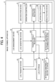
The functional configuration of the image forming apparatus 2 according to a first embodiment will be described. FIG. 4 is a block diagram illustrating an exemplary functional configuration of the image forming apparatus 2. As illustrated in FIG. 4, the image forming apparatus 2 includes a job execution device 21, a log management device 22, a log transfer device 23, a log storage 24, a retention abnormality history storage 25, and an operation controller 26.
The log storage 24 and the retention abnormality history storage 25 are achieved by a nonvolatile memory such as the HD 909 in FIG. 2, and the job execution device 21, the log management device 22, the log transfer device 23, and the operation controller 26 are achieved by executing a predetermined program by the CPU 901 in FIG. 2.
In FIG. 4, the log management device 22 receives a log accumulation request from the job execution device 21 in response to job execution, generates a log related to the job, and transfers the generated log to the log accumulation server 4 via the log transfer device 23. The transferred log is stored in the log accumulation server 4. When a log transfer device to the log accumulation server 4 fails due to a failure or the like of the image forming apparatus 2, the log management device 22 stores the log which have failed to be transferred as a retained log in the log storage 24, and counts the number of the retained logs.
When retention abnormality occurs in which the count number of the retained logs by the log management device 22 becomes equal to or more than a predetermined threshold value, the operation controller 26 receives a notification indicating the occurrence of the retention abnormality from the log management device 22, stops the operation of the image forming apparatus 2, and then reactivates the image forming apparatus 2. After the operation controller 26 reactivates the image forming apparatus 2, the retained logs stored in the log storage 24 are transferred to the log accumulation server 4 via the log transfer device 23. When the transfer is successful, the image forming apparatus 2 releases to stop the operation, and restart the operation. The detailed function of each unit will be described below.
The job execution device 21 receives an operation for indicating a job execution instruction operated by the user, and executes a job such as copying, scanning, printing, and facsimileing. After executing the job, the job execution device 21 requests the log management device 22 to store the log relating to the job to the log accumulation server 4.
The log management device 22 includes a log generating device 221, a transfer result receiver 222, and a retention abnormality determination device 223, and provides functions such as log generation, transfer instruction, and determination of log retention abnormality.
The log generating device 221 responds to a log accumulation request received from the job executor 21 to generate a log corresponding to the request. Then, the log generating device 221 outputs the generated log to the log transfer device 23, and instructs a log transfer.
The log transfer device 23 transfers the log to the log accumulation server 4 in response to the log transfer instructed by the log generating device 221. The log transfer device 23 detects successful transfer or failed transfer to the log accumulation server 4, and notifies the detection result to the transfer result receiver 222.
The transfer result receiver 222 receives a notification indicating the successful transfer or failed transfer from the log transfer device 23. When the notification indicates the failed transfer of the log, the transfer result receiver 222 outputs the log related to the failed transfer acquired from the log generating device 221 to the log storage 24 to store the log as a retained log, and notifies the retention abnormality determination device 223 of the failed transfer.
After the count number of the retained logs becomes equal to or more than the predetermined threshold value, and the image forming apparatus 2 is reactivated, when the transfer of the retained logs stored in the log storage 24 to the log accumulation server 4 fails, the transfer result receiver 222 notifies the operation stopper 262 of the failed transfer. On the other hand, when the transfer is successful, the transfer result receiver 222 notifies an operation restarter 263 of the successful transfer.
The retention abnormality determination device 223 determines log retention abnormality based on the number of the retained logs. When retention abnormality occurs, the retention abnormality determination device 223 notifies a reactivation device 261 and the operation stopper 262 of the retention abnormality.
More specifically, the retention abnormality determination device 223 counts the number of the retained logs in response to the notification indicating the failed transfer from the transfer result receiver 222. When the count number of the retained logs becomes equal to or more than the predetermined threshold value, the retention abnormality determination device 223 notifies the reactivation device 261 and the operation stopper 262 of the occurrence of the log retention abnormality.
The method for determining the log retention abnormality is not limited to the above. As another example of the determination method, the retention abnormality determination device 223 may responds to a notification indicating the failed transfer to add the data size of the retained log, and may determine the occurrence of the log retention abnormality when the accumulated data size of the added retained logs becomes equal to or greater than a predetermined threshold. As still another example, the retention abnormality determination device 223 may acquire information regarding the number or the data size of retained logs by referring to the log storage 24, and may determine the occurrence of the log retention abnormality based on the acquired information.
Each of the threshold of the number and the threshold of the size is determined in advance based on the maximum capacity storable in the log storage 24 and the like. Each of the threshold of the number and the threshold of the size is an example of the predetermined threshold.
When the log retention abnormality occurs, the retention abnormality determination device 223 outputs information relating to the log retention abnormality such as the occurrence date and time and the job information in which the retained log occurs to the retention abnormality history storage 25, in order to store the information as a retention abnormality history. Storing the retention abnormality history allows to notify a serviceman who maintains and manages the image forming apparatus 2 when the same retention abnormality occurs a plurality of times, and to promote to eliminate the log retention.
The operation controller 26 includes the reactivation device 261, the operation stopper 262, and the operation restarter 263, and provides a control function of the image forming apparatus 2 which responds to the success or failure of the log transfer.
When the operation stopper 262 is notified of the occurrence of the log retention abnormality from the retention abnormality determination device 223, the operation stopper 262 notifies the respective units in the image forming apparatus 2 of the log retention abnormality, and stops the operation of the image forming apparatus 2. After stopping the operation of the image forming apparatus 2, the reactivation device 261 reactivates the image forming apparatus 2.
After the reactivation device 261 reactivates the image forming apparatus 2, the log transfer device 23 transfers the retained log stored in the log storage 24 again to the log accumulation server 4 under a predetermined condition. When the transfer fails, the operation stopper 262 stops operating the image forming apparatus 2 under the predetermined condition in response to a notification notifying the failed transfer from the transfer result receiver 222. On the other hand, when the transfer is successful, the operation restarter 263 releases to stop operating the image forming apparatus 2 in response to a notification notifying the successful transfer from the transfer result receiver 222, and restarts the operation of the image forming apparatus 2.
The operation of the image forming apparatus 2 according to the first embodiment will be described with reference to FIGS. 5 and 6. FIG. 5 is a sequence diagram illustrating an example of the operation of the image forming apparatus 2 from the time when a job is executed to the time when the image forming apparatus 2 is reactivated based on the number of retained logs.
In step S51, the job execution device 21 receives an operation indicating a job execution instruction operated by the user, and executes the job.
In step S52, the job execution device 21 requests the log management device 22 to store a log relating to the executed job in the log accumulation server 4.
In step S53, the log generating device 221 in the log management device 22 generates the log in response to the log accumulation request from the job execution device 21.
In step S54, the log generating device 221 outputs the generated log to the log transfer device 23, and instructs the log transfer device 23 to transfer the log to the log accumulation server 4.
In step S55, in response to the log transfer instruction, the log transfer device 23 transfers the log input from the log generating device 221 to the log accumulation server 4.
In step S56, the log transfer device 23 detects successful transfer or failed transfer to the log accumulation server 4. When the transfer fails, the log transfer device 23 notifies the log management device 22 of the failed transfer.
In step S57, the transfer result receiver 222 in the log management device 22 acquires the log of the failed transfer from the log generating device 221 in response to the failed transfer notification, and outputs the log to the log storage 24, so as to store the log as a retained log in the log storage 24. The transfer result receiver 222 notifies the retention abnormality determination device 223 in the log management device 22 of the failed transfer.
In step S58, the retention abnormality determination device 223 counts the number of the retained logs in response to the notification indicating the failed transfer.
When the count number of the retained logs becomes equal to or greater than a predetermined threshold value, in step S59, the retention abnormality determination device 223 notifies the operation controller 26 of the occurrence of the log retention abnormality.
In step S60, the retention abnormality determination device 223 outputs information related to the retention abnormality such as the occurrence date and time of the log retention abnormality and the job information in which the retained log has occurred to the retention abnormality history storage 25, so as to store the information in the retention abnormality history storage 25.
In step S61, the operation stopper 262 in the operation controller 26 notifies the job execution device 21 of the log retention abnormality, so as to stop the operation of the job execution device 21.
In step S62, the operation stopper 262 notifies the log management device 22 of the log retention abnormality, so as to stop the operation of the log management device 22.
In step S63, the operation stopper 262 notifies the log transfer device 23 of the log retention abnormality, so as to stop the operation of the log transfer device 23. The operation stopper 262 notifies each unit in the image forming apparatus 2 of the log retention abnormality, so as to stop the operation of the image forming apparatus 2.
In step S64, the reactivation device 261 in the operation controller 26 reactivates the image forming apparatus 2.
In this manner, the image forming apparatus 2 can stop the operation of the image forming apparatus 2 based on the log retention abnormality, and reactivate the image forming apparatus 2 after stopping the operation.
FIG. 6 is a flowchart illustrating an example of an operation of the image forming apparatus 2 after the image forming apparatus 2 is reactivated based on the number of retained logs until the operation of the image forming apparatus 2 is restarted or stopped.
In step S71, the reactivation device 261 reactivates the image forming apparatus 2.
In step S72, the log transfer device 23 acquires the number of the retained logs in the log storage 24.
In step S73, the log transfer device 23 determines whether the number of the acquired retained logs is one or more.
In step S73, when the number of the retained logs is not one or more (step S73, No), the image forming apparatus 2 ends the operation.
In step S73, when the number of the retained logs is one or more (step S73, Yes), the log transfer device 23 transfers the retained log(s) in the log storage 24 to the log accumulation server 4 in step S74.
In step S75, the log transfer device 23 determines whether the log transfer has failed.
When the log transfer device 23 determines in step S75 that the log transfer has not failed (step S75, No), the process proceeds to step S79.
In step S75, when the log transfer device 23 determines that the log transfer has failed (step S75, Yes), in step S76, the job execution device 21 receives an operation indicating an execution instruction of the job operated by the user, and executes the job.
In step S77, the retention abnormality determination device 223 determines whether the number of the retained logs is equal to or greater than a threshold value.
In step S77, when the retention abnormality determination device 223 determines that the number of the retained logs is equal to or greater than the threshold value (step S77, Yes), the operation stopper 262 stops the operation of the image forming apparatus 2 in step S78.
In step S77, when the retention abnormality determination device 223 determines that the number of the retained logs is not greater than or equal to the threshold value (step S77, No), in step S79, the operation restarter 263 releases to stop the operation of the image forming apparatus 2, and restarts the operation of the image forming apparatus 2.
In this manner, the image forming apparatus 2 can restart the operation after the reactivating due to the log retention abnormality. When the log retention abnormality is not resolved even after the reactivating due to the log retention abnormality, the image forming apparatus 2 can stop the operation, thereby preventing the log lost.
As described above, in the present embodiment, among the logs generated in response to the execution of jobs, the retained log not transferred to the log accumulation server 4 is stored, and the operation of the image forming apparatus 2 is stopped based on the number of the retained logs, and the image forming apparatus 2 is reactivated. In the case where the log retention abnormality occurs, the operation of the image forming apparatus 2 is stopped. Therefore, it is possible to appropriately prevent any retained log in the log storage 24 from disappearing by deleting an old log from the log storage 24 or not storing a new log into the log storage 24 due to the excess of the maximum storage capacity of the log storage 24.
Log transfer may fail due to the occurrence of a memory full or the occurrence of an internal error of the image forming apparatus 2, and log retention abnormality may occur. In such a case, the retention abnormality is resolved by reactivating the image forming apparatus 2. In the embodiment of the present invention, the image forming apparatus 2 is reactivated after stopping the operation. Therefore, in the embodiment of the present invention, after suppressing the use of the image forming apparatus 2 by stopping the operation of the image forming apparatus 2, it is possible to resolve the log retention abnormality caused by the occurrence of the memory full or the internal error, and appropriately restart the use of the image forming apparatus 2 by the user.
Even after reactivating the image forming apparatus 2, when the log retention abnormality is not resolved, it is possible to prevent any log from being lost because the operation of the image forming apparatus 2 is stopped.
An image forming apparatus 2 a according to a second embodiment will be described. The description of the same components as those of the embodiment described above will be omitted.
In case where log retention abnormality occurs, when an image forming apparatus 2 a is automatically reactivated, the user of the image forming apparatus 2 a cannot grasp the situation, so that the user may be confused. In the embodiment of the present invention, when log retention abnormality occurs, a notification screen for notifying the user of reactivating the image forming apparatus 2 a is displayed before reactivating the image forming apparatus 2 a.
Further, log retention abnormality may occur due to the fact that setting information for transferring a log to the log accumulation server 4 such as a uniform resource locator (URL) and a port number of the log accumulation server 4 set in the image forming apparatus 2 a (hereinafter referred to as transfer setting information) is incorrect. In such a case, the log retention abnormality is resolved by changing the transfer setting information. Accordingly, in the embodiment of the present invention, after reactivating the image forming apparatus 2 a due to the log retention abnormality, an input screen on which the user inputs the transfer setting information is displayed.
FIG. 7 is a block diagram illustrating an exemplary functional configuration of the image forming apparatus 2 a according to the present embodiment. As illustrated in FIG. 7, the image forming apparatus 2 a includes a log management device 22 a, a display 27, and an information setting device 28. The log management device 22 a includes a retention abnormality determination device 223 a.
The retention abnormality determination device 223 a determines log retention abnormality based on the number of retained logs. In the case where the retention abnormality occurs, the retention abnormality determination device 223 a notifies the reactivation device 261, the operation stopper 262, and the display 27 of the retention abnormality.
When the display 27 receives the notification of the occurrence of the retention abnormality from the retention abnormality determination device 223, the display 27 displays a notification screen 81 for notifying the user of reactivating the image forming apparatus 2 a (referring to FIG. 8), on the panel display 940 a in FIG. 2, before reactivating the image forming apparatus 2 a. After the reactivation device 261 reactivates the image forming apparatus 2 a, the display 27 displays an input screen 91 on which the user inputs the transfer setting information for transferring a log (referring to FIG. 9), on the panel display 940 a.
The display 27 is an example of a first display, and is an example of a second display. The first display for displaying the notification screen and the second display for displaying the input screen may be separate components.
The information setting device 28 changes the transfer setting information on the basis of information input by the user via the input screen 91.
FIG. 8 is a diagram illustrating an example of the notification screen for reactivating. As illustrated in FIG. 8, the notification screen 81 indicating that log retention abnormality has occurred and that the device (image forming apparatus 2 a) will be reactivated after thirty (30) seconds is displayed on the panel display 940 a in the image forming apparatus 2 a. The example in FIG. 8 illustrates that the image forming apparatus 2 a reactivates after thirty (30) seconds. The time required for the image forming apparatus 2 to reactivate after the notification by the notification screen 81 may be arbitrarily set by the user.
A reactivation button 82 in FIG. 8 is a button for immediately reactivating in response to touching by the user. The reactivation button 82 allows to reduce the waiting time of the user until the image forming apparatus 2 reactivates.
FIG. 9 is a diagram illustrating an example of the input screen 91 for the transfer setting information. An edit box 92 is a box for inputting the URL of the log accumulation server 4. An edit box 93 is a box for inputting the port number of the log transfer.
After inputting into the edit boxes 92 and 93, when the user touches an OK button 94, the setting information for the URL is changed to the setting information input to the edit box 92. The setting information for the port number is changed to the setting information input to the edit box 93. When the user touches a cancel button 95, the transfer setting information is not changed.
FIG. 10 is a flowchart illustrating an example of the operation of the image forming apparatus 2 a after the image forming apparatus 2 is reactivated based on the number of retained logs until the operation of the image forming apparatus 2 is restarted or stopped.
In step S101, the retention abnormality determination device 223 a determines log retention abnormality based on the number of retained logs. When retention abnormality occurs, the retention abnormality determination device 223 a notifies the reactivation device 261, the operation stopper 262, and the display 27 of the retention abnormality.
In step S102, the display 27 reactivates the image forming apparatus 2 a, and displays the notification screen 81 for notifying the user on the panel display 940 a.
In step S103, the display 27 determines whether thirty (30) seconds have elapsed after the display of the notification screen 81 or whether the user has touched the reactivation button 82 on the notification screen 81.
When the display 27 determines in step S103 that thirty (30) seconds have elapsed after the display of the notification screen 81 or the user has touched the reactivation button 82 (step S103, Yes), the process proceeds to step S104. When the display 27 does not determine that thirty (30) seconds have elapsed after the display of the notification screen 81 or the user has touched the reactivation button 82 (step S103, No), the operation of step S103 is repeated again.
Since the operations in steps S104 to S106 are the same as the operations in steps S61 to S63 in FIG. 6, duplicate description will be omitted.
After step S106, in step S107, the display 27 displays the input screen 91 on which the user inputs the transfer setting information.
In step S108, the display 27 determines whether the user has touched the OK button 94 on the input screen 91.
When the display 27 determines in step S108 that the user has touched the OK button 94, the information setting device 28 changes the transfer setting information based on the information input by the user on the input screen 91. Thereafter, the process proceeds to step S111.
In step S108, when the display 27 determines that the user has not touched the OK button 94, the information setting device 28 does not change the transfer setting information. Thereafter, the process proceeds to step S111.
Since the operations in steps S111 to S116 thereafter are the same as the operations in steps S64 to S69 in FIG. 6, duplicate description will be omitted.
In FIG. 10, whether log retention abnormality has occurred is determined in step S114. Therefore, the transfer setting information can be changed between the reactivating of the image forming apparatus 2 a (step S104) and step S114. Therefore, the operations of steps S107 to S110 may be inserted in any steps between steps S104 and S114.
As described above, in the embodiment of the present invention, when log retention abnormality occurs, the notification screen which notifies to reactivate the image forming apparatus 2 a is displayed. Thus, in the embodiment of the present invention, since the user can recognize that the image forming apparatus 2 a is reactivated, it is possible to reactivate the image forming apparatus 2 a without confusing the user.
In the embodiment of the present invention, after the image forming apparatus 2 a is reactivated by the log retention abnormality, the input screen on which the user inputs the transfer setting information is displayed. Thus, when log retention abnormality occurs due to the erroneous transfer setting information, the embodiment can eliminate the log retention abnormality.
Although the embodiments of the present invention have been described above, the present invention is not limited to the above-described embodiments specifically disclosed, and various modifications and changes can be made without departing from the scope of the claims.
Although the image forming apparatus 2 is described as an example of the information processing apparatus in the above-described embodiments, the present invention is not limited thereto. The information processing apparatus may be a projector (PJ), an interactive white board (IWB: a white board having an electronic blackboard function capable of mutual communication), an output device such as a digital signage, a head up display (HUD) device, an industrial machine, an imaging device, a sound collector, a medical device, a network home appliance, an automobile (Connected Car), a notebook personal computer (PC), a mobile phone, a smartphone, a tablet terminal, a game console, a personal digital assistant (PDA), a digital camera, a wearable PC or a desktop PC, as long as the information processing apparatus has a communication function.
The embodiments of the present invention include a program. For example, the program causes a computer to execute processes of storing a retained log that has not been transferred to an external device among logs generated in response to the execution of jobs, and reactivating the information processing apparatus based on the number of the retained logs. With this program, it is possible to obtain the same effect as the above-described information processing system.
The embodiments of the present invention include an information processing method. For example, the information processing method includes storing a retained log that has not been transferred to an external device among logs generated in response to the execution of jobs, and reactivating the information processing apparatus based on the number of the retained logs. With this information processing method, it is possible to obtain the same effect as the above-described information processing system.
The above-described embodiments are illustrative and do not limit the present invention. Thus, numerous additional modifications and variations are possible in light of the above teachings. For example, elements and/or features of different illustrative embodiments may be combined with each other and/or substituted for each other within the scope of the present invention.
Any one of the above-described operations may be performed in various other ways, for example, in an order different from the one described above.
Each of the functions of the described embodiments may be implemented by one or more processing circuits or circuitry. Processing circuitry includes a programmed processor, as a processor includes circuitry. A processing circuit also includes devices such as an application specific integrated circuit (ASIC), digital signal processor (DSP), field programmable gate array (FPGA), and conventional circuit components arranged to perform the recited functions.

Claims (10)

The invention claimed is:
1. An information processing apparatus comprising:
a memory that stores a retained log which has not, been transferred to an external device, among a plurality of logs generated in response to execution of a job; and
circuitry configured to stop operating the information processing apparatus and reboot the information processing apparatus, based on a number of retained logs,
wherein the circuitry determines whether to restart or stop operating the information processing apparatus based on a result of transferring the retained log to the external device after rebooting the information processing apparatus.
2. The information processing apparatus according to claim 1,
wherein the circuitry reboots the information processing apparatus when the number of retained logs is equal to or greater than a threshold value.
3. The information processing apparatus according to claim 1,
wherein the circuitry transfers the retained log to the external device after rebooting the information processing apparatus, and, restarts operating the information processing apparatus when the circuitry succeeds transferring the retained log.
4. The information processing apparatus according to claim 1,
wherein the circuitry transfers the retained log to the external device after rebooting the information processing apparatus, and stops operating the information processing apparatus when the transfer fails.
5. The information processing apparatus according to claim 1,
wherein the memory further stores a history of retention abnormality in which the number of retained logs becomes equal to or greater than a threshold value.
6. The information processing apparatus according to claim 1,
wherein the circuitry controls a display to display a notification screen for notifying occurrence of retention abnormality in which a number of the retained logs becomes equal to or greater than a threshold value after rebooting the information processing apparatus.
7. The information processing apparatus according to claim 1,
wherein the circuitry controls a display to display an input screen allowing a user to input setting information for transferring the log to the external device after rebooting the information processing apparatus.
8. An information processing system comprising:
the information processing apparatus according to claim 1; and
a server configured to store the log transferred, wherein the server operates as the external device.
9. An information processing system comprising:
an information processing apparatus; and
a server communicably connected to the information processing apparatus via a network,
wherein the information processing apparatus includes first circuitry configured to transfer to the server a log generated in response to execution of a job,
wherein the server includes a memory that stores the log transferred, and
wherein the first circuitry stores in the memory a retained log which has not been transferred to the server, among a plurality of generated logs,
wherein the first circuitry stops operating the information processing apparatus and reboots the information processing apparatus, based on a number of retained logs, and
wherein the first circuitry determines whether to restart or stop operating the information processing apparatus based on a result of transferring the retained log after rebooting the information processing apparatus.
10. An information processing method executed by an information processing apparatus, the method comprising;
storing in a memory a retained log which has not been transferred to an external device, among a plurality of logs generated in response to execution of a job;
stopping operating the information processing apparatus and rebooting the information processing apparatus, based on a number of retained logs, and
determining whether to restart or stop operating the information processing apparatus based on a result of transferring the retained log to the external device after rebooting the information processing apparatus.
US16/860,155 2019-05-17 2020-04-28 Information processing apparatus, information processing system, and information processing method Active 2040-08-07 US11269680B2 (en)

Applications Claiming Priority (3)

Application Number Priority Date Filing Date Title
JPJP2019-093330 2019-05-17
JP2019093330A JP7192655B2 (en) 2019-05-17 2019-05-17 Information processing device, information processing system, program, and information processing method
JP2019-093330 2019-05-17

Publications (2)

Publication Number Publication Date
US20200364079A1 US20200364079A1 (en) 2020-11-19
US11269680B2 true US11269680B2 (en) 2022-03-08

Family

ID=73222098

Family Applications (1)

Application Number Title Priority Date Filing Date
US16/860,155 Active 2040-08-07 US11269680B2 (en) 2019-05-17 2020-04-28 Information processing apparatus, information processing system, and information processing method

Country Status (2)

Country Link
US (1) US11269680B2 (en)
JP (1) JP7192655B2 (en)

Cited By (1)

* Cited by examiner, † Cited by third party
Publication number Priority date Publication date Assignee Title
US20220179681A1 (en) * 2020-12-07 2022-06-09 Ricoh Company, Ltd. Information processing apparatus, information processing method, and recording medium

Citations (6)

* Cited by examiner, † Cited by third party
Publication number Priority date Publication date Assignee Title
JP2007174186A (en) 2005-12-21 2007-07-05 Ricoh Co Ltd Information unit, and computer readable recording medium
US20070271317A1 (en) * 2004-08-16 2007-11-22 Beinsync Ltd. System and Method for the Synchronization of Data Across Multiple Computing Devices
JP2011039720A (en) 2009-08-10 2011-02-24 Hitachi Solutions Ltd Log monitoring program and log monitoring system
US20170353615A1 (en) * 2016-06-07 2017-12-07 Canon Kabushiki Kaisha Image forming apparatus, information processing apparatus, method of controlling image forming apparatus, method of controlling information processing apparatus, and storage medium
US20190258558A1 (en) * 2018-02-21 2019-08-22 International Business Machines Corporation Feedback tuples for detecting data flow anomalies in stream computing environment
US20190394343A1 (en) * 2018-06-22 2019-12-26 Brother Kogyo Kabushiki Kaisha Image processing apparatus, method, and computer-readable medium for providing appropriate log image data

Family Cites Families (1)

* Cited by examiner, † Cited by third party
Publication number Priority date Publication date Assignee Title
JP2008165606A (en) * 2006-12-28 2008-07-17 Ricoh Co Ltd Electronic equipment and program to be executed by computer

Patent Citations (6)

* Cited by examiner, † Cited by third party
Publication number Priority date Publication date Assignee Title
US20070271317A1 (en) * 2004-08-16 2007-11-22 Beinsync Ltd. System and Method for the Synchronization of Data Across Multiple Computing Devices
JP2007174186A (en) 2005-12-21 2007-07-05 Ricoh Co Ltd Information unit, and computer readable recording medium
JP2011039720A (en) 2009-08-10 2011-02-24 Hitachi Solutions Ltd Log monitoring program and log monitoring system
US20170353615A1 (en) * 2016-06-07 2017-12-07 Canon Kabushiki Kaisha Image forming apparatus, information processing apparatus, method of controlling image forming apparatus, method of controlling information processing apparatus, and storage medium
US20190258558A1 (en) * 2018-02-21 2019-08-22 International Business Machines Corporation Feedback tuples for detecting data flow anomalies in stream computing environment
US20190394343A1 (en) * 2018-06-22 2019-12-26 Brother Kogyo Kabushiki Kaisha Image processing apparatus, method, and computer-readable medium for providing appropriate log image data

Cited By (2)

* Cited by examiner, † Cited by third party
Publication number Priority date Publication date Assignee Title
US20220179681A1 (en) * 2020-12-07 2022-06-09 Ricoh Company, Ltd. Information processing apparatus, information processing method, and recording medium
US11954519B2 (en) * 2020-12-07 2024-04-09 Ricoh Company, Ltd. Information processing apparatus, method, and recording medium controlling execution of a process based on the amount of a type of log data stored

Also Published As

Publication number Publication date
US20200364079A1 (en) 2020-11-19
JP7192655B2 (en) 2022-12-20
JP2020188421A (en) 2020-11-19

Similar Documents

Publication Publication Date Title
US11778110B2 (en) Image processing apparatus displaying a home screen in a fixed button mode in a state where acquisition of a recommended button information is unavailable
US10218862B2 (en) Information processing terminal, image forming apparatus, information processing method, and recording medium for setting a home screen
US8154760B2 (en) Image forming apparatus, content display method, and computer program product
US11269680B2 (en) Information processing apparatus, information processing system, and information processing method
US9258438B2 (en) Information processing apparatus, information processing terminal, and information processing system
JP7367471B2 (en) Information processing device, file guarantee method, and file guarantee program
US9794437B2 (en) Information processing apparatus, information processing system, and information processing method
US11178298B2 (en) Information processing apparatus and non-transitory computer readable medium
JP7279415B2 (en) Information processing device, information processing method, and program
JP7424014B2 (en) Information processing device, fault management system, fault management method, and program
JP7163798B2 (en) Information processing device, control method, and program
US11445090B2 (en) Information processing apparatus, information processing system, and information processing method for executing applications on which use permission is granted
JP7167789B2 (en) Information processing apparatus, information processing method, program, and image forming system
JP7334452B2 (en) User support system
JP7318228B2 (en) Information processing device, control method, and program
US11729340B2 (en) Information processing server, method, and recording medium
US20230297298A1 (en) Information processing apparatus, information processing system, information processing method, image forming apparatus, and image forming system
JP7306243B2 (en) Information processing device, home screen display method, and home screen display program
JP7404932B2 (en) Information processing device and program
US11445074B2 (en) Information processing device, touch panel display method, and recording medium
US10917531B2 (en) Operation apparatus, information processing system, and operation method for outputting a message by voice sound
US20230376300A1 (en) Information processing apparatus, log storage method, and non-transitory recording medium
US20220124217A1 (en) Electronic apparatus, system, method for managing destination information, and non-transitory recording medium
JP2022060789A (en) Electronic apparatus, control method for electronic apparatus and control program for electronic apparatus
JP2023169781A (en) Information processing apparatus, information processing method, and program

Legal Events

Date Code Title Description
AS Assignment

Owner name: RICOH COMPANY, LTD., JAPAN

Free format text: ASSIGNMENT OF ASSIGNORS INTEREST;ASSIGNOR:MINAMI, KOHICHIROH;REEL/FRAME:052509/0540

Effective date: 20200421

FEPP Fee payment procedure

Free format text: ENTITY STATUS SET TO UNDISCOUNTED (ORIGINAL EVENT CODE: BIG.); ENTITY STATUS OF PATENT OWNER: LARGE ENTITY

STPP Information on status: patent application and granting procedure in general

Free format text: APPLICATION DISPATCHED FROM PREEXAM, NOT YET DOCKETED

STPP Information on status: patent application and granting procedure in general

Free format text: DOCKETED NEW CASE - READY FOR EXAMINATION

STPP Information on status: patent application and granting procedure in general

Free format text: NON FINAL ACTION MAILED

STPP Information on status: patent application and granting procedure in general

Free format text: RESPONSE TO NON-FINAL OFFICE ACTION ENTERED AND FORWARDED TO EXAMINER

STCF Information on status: patent grant

Free format text: PATENTED CASE