US11269286B2 - Free stop based hinge apparatus - Google Patents
Free stop based hinge apparatus Download PDFInfo
- Publication number
- US11269286B2 US11269286B2 US16/500,484 US201816500484A US11269286B2 US 11269286 B2 US11269286 B2 US 11269286B2 US 201816500484 A US201816500484 A US 201816500484A US 11269286 B2 US11269286 B2 US 11269286B2
- Authority
- US
- United States
- Prior art keywords
- axis
- free stop
- fixing
- groove
- combination
- Prior art date
- Legal status (The legal status is an assumption and is not a legal conclusion. Google has not performed a legal analysis and makes no representation as to the accuracy of the status listed.)
- Active, expires
Links
Images


Classifications
-
- G—PHYSICS
- G03—PHOTOGRAPHY; CINEMATOGRAPHY; ANALOGOUS TECHNIQUES USING WAVES OTHER THAN OPTICAL WAVES; ELECTROGRAPHY; HOLOGRAPHY
- G03G—ELECTROGRAPHY; ELECTROPHOTOGRAPHY; MAGNETOGRAPHY
- G03G21/00—Arrangements not provided for by groups G03G13/00 - G03G19/00, e.g. cleaning, elimination of residual charge
- G03G21/16—Mechanical means for facilitating the maintenance of the apparatus, e.g. modular arrangements
- G03G21/1642—Mechanical means for facilitating the maintenance of the apparatus, e.g. modular arrangements for connecting the different parts of the apparatus
- G03G21/1647—Mechanical connection means
-
- F—MECHANICAL ENGINEERING; LIGHTING; HEATING; WEAPONS; BLASTING
- F16—ENGINEERING ELEMENTS AND UNITS; GENERAL MEASURES FOR PRODUCING AND MAINTAINING EFFECTIVE FUNCTIONING OF MACHINES OR INSTALLATIONS; THERMAL INSULATION IN GENERAL
- F16C—SHAFTS; FLEXIBLE SHAFTS; ELEMENTS OR CRANKSHAFT MECHANISMS; ROTARY BODIES OTHER THAN GEARING ELEMENTS; BEARINGS
- F16C11/00—Pivots; Pivotal connections
- F16C11/04—Pivotal connections
-
- G—PHYSICS
- G03—PHOTOGRAPHY; CINEMATOGRAPHY; ANALOGOUS TECHNIQUES USING WAVES OTHER THAN OPTICAL WAVES; ELECTROGRAPHY; HOLOGRAPHY
- G03G—ELECTROGRAPHY; ELECTROPHOTOGRAPHY; MAGNETOGRAPHY
- G03G15/00—Apparatus for electrographic processes using a charge pattern
- G03G15/50—Machine control of apparatus for electrographic processes using a charge pattern, e.g. regulating differents parts of the machine, multimode copiers, microprocessor control
- G03G15/5016—User-machine interface; Display panels; Control console
-
- G—PHYSICS
- G06—COMPUTING; CALCULATING OR COUNTING
- G06F—ELECTRIC DIGITAL DATA PROCESSING
- G06F1/00—Details not covered by groups G06F3/00 - G06F13/00 and G06F21/00
- G06F1/16—Constructional details or arrangements
- G06F1/1613—Constructional details or arrangements for portable computers
- G06F1/1633—Constructional details or arrangements of portable computers not specific to the type of enclosures covered by groups G06F1/1615 - G06F1/1626
- G06F1/1675—Miscellaneous details related to the relative movement between the different enclosures or enclosure parts
- G06F1/1681—Details related solely to hinges
Definitions
- an image forming apparatus such as a copier, a printer, or the like, includes a display that provides a user with information about various types of setting states, printing states, and the like.
- a display 7 is installed at a main body 3 of an image forming apparatus 1 through a support part 5 .
- an angle of the display 7 may be variously changed on an axis 8 as shown in FIG. 2 so as to position a screen thereof within a viewing angle of a user.
- the display 7 is connected to the support part 5 through a hinge that operates as the axis 8 and is freely stoppable.
- an free stop hinge may have one axis but uses two axes if a rotation axis is far away. In this case, an eccentricity occurs between the two axes, and thus an axis alignment is required.
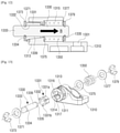
- FIG. 1 is a perspective view of an image forming apparatus including a display
- FIG. 2 is a schematic view illustrating a state of the display of FIG. 1 that is freely stopped;
- FIG. 3 is a perspective view illustrating a hinge apparatus that is disposed on a back surface of a display, according to an embodiment of the present disclosure.
- FIG. 4 is a perspective view illustrating a rotation axis device and a side of an axis support part of a display with which the axis rotation device is combined;
- FIG. 5 is a perspective view illustrating a free stop hinge device and an other side of the axis support part of the display with which the free stop hinge device is combined;
- FIG. 6 is a cross-sectional view taken along a line VI-VI of FIG. 3 ;
- FIG. 7 is an exploded perspective view of a free stop hinge device
- FIG. 8 is a cross-sectional view taken along a line VIII-VIII of FIG. 5 ;
- FIG. 9 is a schematic view illustrating a state of a free stop hinge device that is movable up and down in order to align an axis by a gap formed in a combination groove of the axis support part into which a combination protrusion of a shaft of the free stop hinge device is combined;
- FIG. 10 is a cross-sectional view of a free stop hinge device according to another embodiment of the present disclosure.
- FIG. 11 is a plan view of a free stop hinge device according to another embodiment of the present disclosure.
- FIG. 12 is a cross-sectional view taken along a line XII-XII of FIG. 11 ;
- FIG. 13 is an exploded perspective view of the free stop hinge device of FIG. 11 ;
- FIG. 14 is a front view of a friction member of FIG. 13 ;
- FIG. 15 is a perspective view of a friction member according to another embodiment of the present disclosure.
- FIG. 16 is a schematic view illustrating a difference between a diameter of the friction member of FIG. 15 and a diameter of a shaft combined with the friction member;
- FIG. 17 is a perspective view illustrating free stop hinge devices that are respectively combined with both sides of an axis support part of a display
- FIGS. 18 and 19 are perspective views respectively illustrating a side and an other side of an axis support part of a display
- FIG. 20 is a schematic view illustrating fixing protrusions of a pair of free stop hinge devices that are respectively combined into fixing grooves of an axis support part of a display so as to be disposed toward directions orthogonal to each other;
- FIG. 21 is an assembly cross-sectional view illustrating a free stop hinge device, as shown in FIG. 8 , and a free stop hinge device, as shown in FIG. 10 , that are respectively combined with a side and an other side of an axis support part of a display;
- FIG. 22 is an exploded perspective view illustrating free stop hinge devices, as shown in FIG. 12 , that are respectively combined with a side and an other side of an axis support part of a display.
- first ‘first’, ‘second’, etc. may be used herein to describe various elements regardless of orders and/or importances, these elements may not be limited by these terms. These terms are merely used to distinguish one element from another. For example, a first element may be termed a second element, and, similarly, a second element may be termed a first element, without departing from the scope of embodiments.
- an object that a hinge apparatus pivotably supports will be limitedly described as a display but is not limited thereto. Therefore, any particular object of which angle is required to be changed and maintained is not limited.
- FIG. 3 is a perspective view of a hinge apparatus 100 that is disposed on a back surface of a display 10 , according to an embodiment of the present disclosure.
- FIG. 4 is a perspective view illustrating a rotation axis device and a side of an axis support part of a display with which the rotation axis device is combined.
- FIG. 5 is a perspective view illustrating a free stop hinge device and an other side of the axis support part of the display with which the free stop hinge device is combined.
- FIG. 6 is a cross-sectional view taken along a line VI-VI of FIG. 3 .
- the hinge apparatus 100 includes a rotation axis device 200 and a free stop hinge device 300 that are respectively combined with both sides of an axis support part 11 formed on the back surface of the display 10 .
- the display 10 may be installed at an image forming apparatus (not shown) so as to display various types of information about printing or the corresponding image forming apparatus.
- the rotation axis device 200 pivotably supports the side of the axis support part 11 so as to pivot the display 10 .
- the rotation axis device 200 includes a first fixing part 210 that is fixed to a main body (not shown) of the image forming apparatus and a first axis part 213 that extends from the first fixing part 210 so as to form a single body with the first fixing part 210 .
- a combination hole 211 through which a combination screw (not shown) penetrates is formed in the first fixing part 210 so as to enable the first fixing part 210 to be installed at a part of the main body of the image forming apparatus through the combination screw.
- the first axis part 213 includes a curved protrusion 215 that convexly protrudes.
- the curved protrusion 215 protrudes from an outer circumference surface of the first axis part 213 having an approximately cylindrical shape along a radius direction of the first axis part 213 .
- the curved protrusion 215 may operate as a kind of ball bearing. Therefore, the first axis part 213 is combined into the first combination groove 13 of the axis support part 11 in a pivotable state.
- the rotation axis device 200 when the rotation axis device 200 is assembled in the axis support part 11 of the display 10 , a freedom degree of taking a posture of the display 10 at a desired angle is secured. Therefore, an eccentricity occurring between a central axis line of the rotation axis device 200 and a central axis line of the free stop hinge device 300 may be easily controlled.
- the first combination groove 13 has an inner circumference surface having a cylindrical shape.
- an angle of the display 10 that is movable with respect to the rotation axis device 200 is a minute angle less than or equal to about 5 degrees.
- the curved protrusion 215 formed on the first axis part 213 having the cylindrical shape may be removed, and a curved protrusion may be formed so as to protrude toward a circumferential direction of a first combination groove along an inner circumference surface 14 of the first combination groove 13 .
- the eccentricity occurring between the central axis line of the rotation axis device 200 and the central axis line of the free stop hinge device 300 may be easily controlled as described above.
- the rotation axis device 200 may be formed of a synthetic resin or a metallic material having a preset hardness.
- the free stop hinge device 300 pivotably supports an other side of the axis support part 11 so as to pivot the display 10 .
- a second axis part 313 that will be described later is inserted into a second combination groove 15 of the axis support part 11 , and a fixing protrusion 333 formed at a front end of a shaft 330 that will be described later is inserted into a fixing groove 17 positioned inside the second combination groove 15 . Therefore, if the display 10 pivots, the shaft 330 pivots along with the display 10 .
- the display 10 may maintain a fixed state thereof at a desired angle by a frictional force occurring between the second axis part 313 and the shaft 330 .
- the free stop hinge device 300 includes a second fixing part 310 that is fixed to the main body of the image forming apparatus and the second axis part 313 that extends from the second fixing part 310 so as to form a single body with the second fixing part 310 .
- a combination hole 301 through which a combination screw (not shown) penetrates is formed in the second fixing part 310 so as to enable the second fixing part 310 to be installed at a part of the main body of the image forming apparatus through the combination screw.
- a combination hole 311 is formed inside a front end of the second axis part 313 so as to penetrate on a central axis line of the second axis part 313 , and a housing groove 315 is formed inside a back end of the second axis part 313 so as to house an elastic member 350 .
- An inner circumference surface 312 is formed in the combination hole 311 so as to have a corn shape of which a diameter becomes gradually smaller from the front end of the second axis part 313 (i.e., a side of the second axis part 313 combined into the second combination groove 15 of the axis support part 11 ) toward the back end of the second axis part 313 . If the shaft 330 pivots when an outer circumference surface 332 of a friction part 331 that will be described later contacts the inner circumference surface 312 of the combination hole 311 , a frictional force occurs between the outer circumference surface 332 of the friction part 331 and the inner circumference surface 312 of the combination hole 311 .
- a fixing protrusion 333 and the friction part 331 inserted into the combination hole 311 of the second axis part 313 are formed at a front end of the shaft 330 , and a groove 335 with which an E-ring 375 is combined is formed in a back end of the shaft 330 .
- the shaft 330 pivots together when the display 10 pivots.
- the friction part 331 may be formed in an approximately corn shape of which a diameter becomes gradually smaller from the front end of the shaft 330 toward the back end of the shaft 330 .
- the shape of the friction part 331 corresponds to a shape of the inner circumference surface 312 of the combination hole 311 .
- the outer circumference surface 332 of the friction part 331 may have an angle ⁇ (refer to FIG. 8 ) enough to trap the friction part 331 in the combination hole 311 so as not to enable the friction part 331 to escape from the combination hole 311 by an elastic force of the elastic member 350 .
- a coil spring may be used as the elastic member 350 , and an elastic member and a coil spring may be denoted by the same reference numeral hereinafter.
- the coil spring 350 is disposed in the housing groove 315 of the second axis part 313 , and a part of the shaft 330 is inserted into the coil spring 350 .
- the coil spring 350 is not separated from the shaft 350 by the E-ring 375 and simultaneously produces an elastic force toward a direction A marked with an arrow (i.e. toward a direction going from the front end of the shaft 330 to the back end of the shaft 330 ).
- This elastic force enables the outer circumference surface 332 of the friction part 331 to pressurize and contact the inner circumference surface 312 of the combination hole 311 .
- the elastic force of the coil spring 350 required in this case may realize a free stop function merely if the frictional force occurring between the outer circumference surface 332 of the friction part 331 and the inner circumference surface 312 of the combination hole 311 is larger than the weight of the display 10 .
- the shaft 330 is pulled by the coil spring 35 toward the direction A marked with the arrow at all times. Therefore, when the free stop hinge device 300 is used for a long time, the outer circumference surface 332 of the friction part 331 and the inner circumference surface 312 of the combination hole 311 mutually evenly wears down. Also, as the shaft 330 moves toward the direction A marked with the arrow by a worn degree, the outer circumference surface 332 of the friction part 331 and the inner circumference surface 312 of the combination hole 311 keep a mutual contact area in a maximum state. Therefore, a replacement of the shaft 330 , which results from lowering of a frictional force caused by a one-sided wear, is not needed.
- a one-sided concentration phenomenon of a weight of the coil spring 350 wears down a structure (i.e., an inner surface of the housing groove 315 or a surface of the E-ring 375 ), which elastically supports the end and the other end of the coil spring 350 , when the display 10 pivots.
- a first washer 371 and a second washer 373 are respectively disposed at the end and the other end of the coil spring 350 .
- the first washer 371 is disposed between the end of the coil spring 350 and the inner surface of the housing groove 315 (e.g., a surface corresponding to a surrounding part of the combination hole 311 ), and the second washer 373 is disposed between the other end of the coil sprint 350 and the E-ring 375 .
- a length of the fixing groove 17 is longer than a width of the fixing protrusion 333 .
- gaps g having preset lengths are respectively formed between an upper end of the fixing protrusion 333 and an upper end of the fixing groove 17 and between a lower end of the fixing protrusion 333 and a lower end of the fixing groove 17 . Therefore, the free stop hinge device 300 may pivot by a preset angle (i.e., less than or equal to about 5 degrees) toward direction Z (i.e., in upper and lower directions) by using axis Y as a rotation center. Therefore, when the free stop hinge device 300 is assembled with an other side of the axis support part 11 , the eccentricity occurring between the central axis line of the free stop hinge device 300 and the central axis line of the rotation axis device 200 may be easily controlled.
- a part forming the free stop hinge device 300 i.e., the second axis part 313 forming a single body with the second fixing part 310 , may be formed of a synthetic resin or a metallic material having a preset hardness.
- the shaft 330 , the elastic member 350 , the first and second washers 371 and 373 , and the E-ring 375 may be formed of metallic materials.
- the friction part 331 of the shaft 330 may have a cross-section having a curved shape as shown in FIG. 10 besides the corn shape.
- FIG. 10 is a cross-sectional view of a free stop hinge device 300 a according to another embodiment of the present disclosure.
- a shaft 330 a of the free stop hinge device 300 a includes a friction part 331 a having an outer circumference surface 332 a that is formed as a convex curved surface.
- An inner circumference surface 312 a of a combination hole of a second axis part 313 which produces a friction with the outer circumference surface 332 a of the friction part 331 a , is formed as a concave curved surface so as to correspond to a shape of the outer circumference surface 332 a of the friction part 331 a.
- a friction area between the outer circumference surface 332 a of the friction part 331 a and the inner circumference surface 312 a of the combination hole increases more than the friction area between the outer circumference surface 332 of the friction part 331 having the corn shape described above and the inner circumference surface 312 of the combination hole 311 . Therefore, this may produce a frictional force larger than a frictional force occurring on a vertical friction surface of an free stop hinge.
- FIG. 11 is a plan view of a free stop hinge device according to another embodiment of the present disclosure.
- FIG. 12 is a cross-sectional view taken along a line XII-XII of FIG. 11 .
- FIG. 13 is an exploded perspective view of the free stop hinge device of FIG. 11 .
- FIG. 14 is a front view of a friction member of FIG. 13 .
- the free stop hinge device 1300 includes a second fixing part 1310 that is fixed to the main body (not shown) of the image forming apparatus and a second axis part 1313 that extends from the second fixing part 1310 to form a single body with the second fixing part 1310 .
- a combination hole 1301 through which a combination screw (not shown) penetrates is formed in the second fixing part 1310 so as to enable the second fixing part 1310 to be installed at a part of the main body of the image forming apparatus through the combination screw.
- a combination hole 1311 that penetrates on a central axis line of the second axis part 1313 is formed inside a front end of the second axis part 1313 , and a housing groove 1315 that houses an elastic member 1350 is formed inside a back end of the second axis part 1313 .
- An inner circumference surface 1314 is formed in the combination hole 1311 so as to have an approximately corn shape of which a diameter becomes gradually smaller from the front end of the second axis part 1313 toward the back end of the second axis part 1313 .
- a plurality of first insertion grooves 1316 are formed in the inner circumference surface 1314 at the same intervals toward a longitudinal direction of the combination hole 1311 .
- a plurality of insertion grooves 1317 are formed in the front end of the combination hole 1311 at the same intervals toward a radial direction. The number of the plurality of first insertion grooves 1316 is the same as the number of the plurality of second insertion grooves 1317 .
- a friction member 1331 includes first, second, and third parts P 1 , P 2 , and P 3 that are divided at equal intervals so as to be reduced when being inserted into the combination hole 1311 .
- the “reduction” means that a whole size of the friction member 1331 is reduced as first through third parts move preset distances toward a center of the friction member 1331 .
- Insertion protrusions 1331 a that are respectively inserted into the first insertion grooves 1316 of the combination hole 1311 are respectively formed on outer circumference surfaces of the first, second, and third parts P 1 , P 2 , and P 3 . If a plurality of insertion protrusions 1331 a are inserted into the plurality of first insertion grooves 1316 when the friction member 1331 is inserted into the combination hole 1311 , the friction member 1331 does not pivot when a shaft 1330 pivots along with the display 10 . Here, a frictional force occurs between the shaft 1330 and the friction member 1331 , and a free stop function may be realized by using the frictional force.
- first, second, and third parts P 1 , P 2 , and P 3 are connected to one another by a plurality of connection ribs 1331 b , of which adjacent parts have elastic forces, so as not to be completely separated from one another.
- the plurality of connection ribs 1331 may be respectively inserted into the plurality of second insertion grooves 1317 of the friction member 1331 .
- a fixing protrusion 1333 and a first groove 1334 into which a first E-ring 1373 is combined are formed at a front end of the shaft 1330
- a second groove 1335 into which a second E-ring 1379 is combined is formed in a back end of the shaft 1330 .
- the shaft 1330 pivots together when the display 10 pivots.
- the shaft 1330 is combined with the second axis part 1313 in a state of penetrating through the friction member 1331 .
- the first E-ring 1373 prevents the friction member 1331 from deviating from the shaft 1330 .
- the first washer 1371 may be positioned between the friction member 1331 and the first E-ring 1373 .
- a coil spring may be used as the elastic member 1350 , and an elastic member and a coil spring are denoted by the same reference numeral.
- the coil spring 1350 is disposed in the housing groove 1315 of the second axis part 1313 , and a part of the shaft 1330 is inserted into the coil spring 1350 .
- the coil spring 1350 is not separated from the shaft 1330 by the second E-ring 1379 and simultaneously produces an elastic force toward a direction B marked with an arrow (i.e., a direction going from a front end of the shaft 1330 toward a back end of the shaft 1330 ).
- the friction member 1331 is pressurized toward the direction B marked with the arrow by the elastic force of the coil spring 1350 . Therefore, as gaps between the first, second, and third parts P 1 , P 2 , and P 3 of the friction member 1331 becomes narrower, inner circumference surfaces 1332 of the first, second, and third parts P 1 , P 2 , and P 3 pressurize and contact the outer circumference surface 1339 of the shaft 1330 .
- the elastic force of the coil spring 1350 required in this case may satisfy a case where a frictional force occurring between the outer circumference surface 1339 of the shaft 1330 and the first, second, and third parts P 1 , P 2 , and P 3 of the friction member 1331 is larger than the weight of the display 10 . If this case is satisfied, the free stop hinge device 1300 may perform a function thereof.
- a one-sided concentration phenomenon of a weight of the coil spring 1350 wears down a structure, which elastically supports the end and the other end of the coil spring 1350 (e.g., an inner surface of the housing groove 1315 or a surface of the second E-ring 1379 ), when the display 10 pivots.
- a second washer 1375 and a third washer 1377 are respectively disposed at the end and the other end of the coil spring 1350 .
- the second washer 1375 is disposed between the end of the coil spring 1350 and the inner surface of the housing groove 1315 (e.g., a surface corresponding to a surrounding part of the combination hole 1311 ), and the third washer 1377 is disposed between the other end of the coil spring 1350 and the second E-ring 1379 .
- the free stop hinge device 1300 constituted as described above produces a frictional force that acts toward a circumferential direction of the shaft 1330 when the display 10 pivots and generates a friction area that are larger than friction areas generated by the free stop hinge devices 300 and 300 a described above. Therefore, if the free stop hinge device 1300 is applied, a free stop function of a display, which has a larger size than displays of the free stop hinge devices 300 and 300 a described above, may be sufficiently realized.
- the friction member 1331 is formed so as to be dived into a plurality of parts P 1 , P 2 , and P 3 but is limited thereto. Therefore, a friction member 2331 including two parts connected to each other by connection ribs 2331 b may be provided as shown in FIG. 15 .
- FIG. 15 is a perspective view of the friction member 2331 according to another embodiment of the present disclosure.
- FIG. 16 is a schematic view illustrating a difference between a diameter the friction member 2331 of FIG. 15 and a diameter of a shaft combined with the friction member 2331 .
- the friction member 2331 has a cylindrical shape, and two parts P 4 and P 5 are connected to each other by a pair of connection ribs 2331 b , which are disposed to be opposite to each other, so as to be reduced.
- the pair of connection ribs 2331 are respectively formed toward longitudinal directions of the parts P 4 and P 5 , and preset spaces 2331 c are formed in the pair of connection ribs 2331 b .
- the pair of connection ribs 2331 b are combined into a pair of insertion grooves (not shown) formed in an inner circumference surface of a combination hole of a second axis part so as to prevent the friction member 2331 from pivoting in the insertion groove of the combination hole.
- the pair of connection ribs 2331 b of the friction member 2331 also perform a function of the insertion protrusion 1331 a of the friction member 1331 described above.
- an internal diameter of the friction member 2331 may be smaller than an external diameter of a shaft 2330 . If the shaft 2330 is inserted into the friction member 2331 when the friction member 2331 is inserted into the combination hole, the parts P 4 and P 5 of the friction member 2332 are pressurized by pressure generated between the friction member 2331 and the shaft 2330 when the friction member 2331 and the shaft 2330 are combined with each other. As a result, inner circumference surfaces 2332 of the parts P 4 and P 5 are pressurized by and contact an outer circumference surface of the shaft 2330 .
- a coil spring for pressurizing the friction member 2331 toward one direction does not need to be applied. Since the coil spring is omissible described above, a plurality of washers and a plurality of E-rings may be omitted.
- a hinge apparatus that supports the display 10 so as to freely stop the display 10 may apply a rotation axis device having no free stop hinge function and a free stop hinge device together.
- FIG. 17 is a perspective view illustrating free stop hinge devices that are respectively combined with both sides of an axis support part of a display.
- FIGS. 18 and 19 are perspective views respectively illustrating a side and an other side of the axis support part of the display.
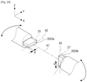
- FIG. 20 is a schematic view illustrating fixing protrusions of a pair of free stop hinge devices that are respectively combined into fixing grooves of the axis support part of the display so as to be disposed in directions orthogonal to each other.
- first and second free stop hinge devices 3301 and 3302 may be displayed at both sides of an axis support part 21 as shown in FIG. 17 .
- the first and second free stop hinge devices 3301 and 3302 have the same configurations as the free stop hinge device 300 of FIG. 8 .
- first and second fixing grooves 25 and 27 formed in the axis support part 21 are formed to be orthogonal to each other so as to control an eccentricity of a central axis line of each of the first and second free stop hinge devices 3301 and 3302 .
- the first fixing groove 25 of the axis support part 21 is formed along axis Y as shown in FIG. 18
- the second fixing groove 27 of the axis support part 21 is formed along axis Z as shown in FIG. 19 .
- fixing protrusions 3333 a and 3333 b of the first and second free stop hinge devices 3301 and 3302 are respectively combined into the first and second fixing grooves 25 and 27 so as to be disposed in directions orthogonal to each other as shown in FIG. 20 .
- gaps g having preset lengths are formed between both ends of the first fixing protrusion 333 a and both ends of the first fixing groove 25 .
- gaps g having preset lengths are formed between upper and lower ends of the second fixing protrusion 3333 b and both ends of the second fixing groove 27 .
- the first free stop hinge device 3301 may pivot at a preset angle (i.e., less than or equal to about 5 degrees) toward the axis Y (i.e., in left and right directions) by using the axis Z as a rotation center.
- the second free stop hinge device 3302 may pivot at a preset angle (i.e., less than or equal to about 5 degrees) toward the axis Z (i.e., in upper and lower directions) by using the axis Y as a rotation center.
- the eccentricity with each of the central axis lines of the first and second free stop hinge devices 3301 and 3302 may be easily controlled.
- FIG. 21 is an assembly cross-sectional view illustrating a free stop hinge device, as shown in FIG. 8 , and a free stop hinge device, as shown in FIG. 10 , that are respectively combined with a side and an other side of an axis support part of a display.
- third and fourth free stop hinge devices 4301 and 4302 having different configurations may be respectively combined with both sides of the axis support part 21 of the display 20 .
- the third free stop hinge device 4301 has the same configuration as the free stop hinge device 300 of FIG. 8
- the fourth free stop hinge device 4302 has the same configuration as the free stop hinge device 300 a of FIG. 10 .
- fixing protrusions 4333 a and 4333 b are respectively disposed at the third and fourth free stop hinge devices 4301 and 4302 so as to be orthogonal to each other in order to control an eccentricity.
- FIG. 22 is an exploded perspective view illustrating free stop hinge devices, as shown in FIG. 12 , that are respectively combined with a side and an other side of an axis support part of a display.
- fifth and sixth free stop hinge devices 5301 and 5302 having the same configurations may be respectively combined with both sides of an axis support part 31 of a display 30 .
- the fifth and sixth free stop hinge devices 5301 and 5302 have the same configurations as the free stop hinge device 1300 of FIG. 12 .
- fixing protrusions 5333 a and 5333 b are respectively disposed at the fifth and sixth free stop hinge devices 5301 and 5302 so as to be orthogonal to each other in order to control an eccentricity.
- a hinge apparatus of the present disclosure includes a pair of free stop hinge devices
- the pair of free stop hinge devices may have the same configurations or different configurations.
- a shaft of a free stop hinge device may be formed of a metallic material
- a friction member of the free stop hinge device may be formed of a metallic material or a synthetic resin having a preset elastic force
- a second fixing part of the free stop hinge device may be formed of a metallic material or a synthetic resin having a preset elastic force.
Abstract
Description
Claims (12)
Applications Claiming Priority (3)
| Application Number | Priority Date | Filing Date | Title |
|---|---|---|---|
| KR10-2017-0132048 | 2017-10-12 | ||
| KR1020170132048A KR20190041065A (en) | 2017-10-12 | 2017-10-12 | Hinge apparatus |
| PCT/KR2018/005339 WO2019074179A1 (en) | 2017-10-12 | 2018-05-10 | Free stop based hinge apparatus |
Publications (2)
| Publication Number | Publication Date |
|---|---|
| US20210109477A1 US20210109477A1 (en) | 2021-04-15 |
| US11269286B2 true US11269286B2 (en) | 2022-03-08 |
Family
ID=66100716
Family Applications (1)
| Application Number | Title | Priority Date | Filing Date |
|---|---|---|---|
| US16/500,484 Active 2038-07-03 US11269286B2 (en) | 2017-10-12 | 2018-05-10 | Free stop based hinge apparatus |
Country Status (3)
| Country | Link |
|---|---|
| US (1) | US11269286B2 (en) |
| KR (1) | KR20190041065A (en) |
| WO (1) | WO2019074179A1 (en) |
Citations (58)
| Publication number | Priority date | Publication date | Assignee | Title |
|---|---|---|---|---|
| US1956040A (en) * | 1932-02-05 | 1934-04-24 | Porcelain Products Inc | Friction hinge |
| US3349427A (en) * | 1965-08-27 | 1967-10-31 | Stanley Works | Hinge |
| US4101227A (en) * | 1977-01-06 | 1978-07-18 | Trw Inc. | Pivot joint |
| US4620344A (en) * | 1985-08-15 | 1986-11-04 | General Electric Company | Friction applying assembly |
| US5075929A (en) * | 1990-07-02 | 1991-12-31 | Industrial Technology Research Institute | Hinge mechanism for a portable apparatus |
| US5206790A (en) * | 1991-07-11 | 1993-04-27 | Zeos International, Ltd. | Pivot and swivel mechanism for lap top display |
| US5239731A (en) * | 1992-06-03 | 1993-08-31 | Lu Sheng N | Hinge device for casings |
| US5715576A (en) * | 1997-02-04 | 1998-02-10 | Liu; Tai-Sheng | Hinge device for coupling two rotatable members |
| US5813789A (en) | 1995-12-07 | 1998-09-29 | Trw Fahrwerksysteme Gmbh & Co. Kg | Ball-and-socket joint |
| JP2000045615A (en) * | 1998-07-31 | 2000-02-15 | Sugatsune Ind Co Ltd | Free stop hinge |
| US6065732A (en) * | 1998-03-30 | 2000-05-23 | Lg Electronics Inc. | Pivotal rotation adjusting apparatus for flat panel display device |
| US6101676A (en) * | 1998-01-27 | 2000-08-15 | Dell Usa, L.P. | Adjustable clutch hinge assembly for portable computer |
| JP2001107941A (en) | 1999-10-08 | 2001-04-17 | Kato Electrical Mach Co Ltd | Tilt hinge |
| US6308377B1 (en) * | 1998-11-26 | 2001-10-30 | Nokia Mobile Phones Ltd. | Hinged electronic device |
| US6381808B1 (en) * | 1999-06-16 | 2002-05-07 | Minoru Kida | Hinge used for note-type computer |
| US20020112319A1 (en) * | 2001-02-21 | 2002-08-22 | Makoto Kida | Hinge |
| JP2002372033A (en) | 2001-06-13 | 2002-12-26 | Masakazu Wakai | Hinge device for notebook personal computer |
| US6532628B2 (en) * | 2000-07-08 | 2003-03-18 | Lg Electronics Inc. | Hinge assembly for LCD monitor |
| US6568034B2 (en) * | 2000-06-20 | 2003-05-27 | Lg Electronics Inc. | Hinge assembly |
| US6701572B2 (en) * | 2000-03-21 | 2004-03-09 | Edscha Ag | Flap hinge |
| US6711001B2 (en) * | 2002-06-17 | 2004-03-23 | Dell Products L.P. | Chassis bushing assembly |
| US6711781B2 (en) * | 2002-08-21 | 2004-03-30 | Lite-On Technology Corporation | Automatic releasing hinge |
| KR20040065556A (en) | 2001-11-08 | 2004-07-22 | 애플 컴퓨터, 인크. | Computer controlled display device |
| US20060130278A1 (en) * | 2004-12-21 | 2006-06-22 | Asustek Computer Inc. | Hinge device with locking function |
| US20060175501A1 (en) | 2005-02-07 | 2006-08-10 | Harald Richter | Universal joint arrangement between an apparatus holder and a support arm or a console |
| US7096534B2 (en) * | 2003-06-06 | 2006-08-29 | Fih Co., Ltd. | Hinge assembly with rotating mechanism |
| US20060216977A1 (en) * | 2005-03-25 | 2006-09-28 | Hideo Kato | Portable equipment |
| US20060262496A1 (en) * | 2005-05-23 | 2006-11-23 | Seung-Won Lee | Portable computer having detachable display |
| US20060272129A1 (en) * | 2005-06-04 | 2006-12-07 | Torqmaster, Inc. | Friction hinge with viscous damping |
| US20060272128A1 (en) * | 2005-06-04 | 2006-12-07 | Torqmaster, Inc. | Friction hinge with angularly dependent torque |
| US20090038119A1 (en) * | 2007-08-07 | 2009-02-12 | Edward Rude | Friction hinge without applied grease |
| US20100077565A1 (en) * | 2008-10-01 | 2010-04-01 | Wei-Kuo Huang | Hinge capable of being positioned at any angle |
| US7832054B2 (en) * | 2006-11-29 | 2010-11-16 | Piolax Inc. | Free stop hinge |
| US20100313384A1 (en) * | 2009-06-11 | 2010-12-16 | Piolax Inc. | Hinge device |
| US20110061197A1 (en) * | 2009-09-16 | 2011-03-17 | Kabushiki Kaisha Strawberry Corporation | Hinge device and electronic instrument using the hinge device |
| US20120023704A1 (en) * | 2006-12-06 | 2012-02-02 | Case Ryan R | Friction Hinge |
| KR101113712B1 (en) * | 2010-12-21 | 2012-02-27 | 주식회사 케이에이치바텍 | Free-stop hinge module for portable device |
| US8209816B2 (en) * | 2009-10-09 | 2012-07-03 | Lang-Mekra North America, Llc | Locking hinge for an exterior vehicle mirror assembly |
| US8251341B2 (en) * | 2008-08-26 | 2012-08-28 | Hong Fu Jin Precision Industry (Shenzhen) Co., Ltd. | Flat-panel display monitor |
| US8254103B2 (en) * | 2009-10-12 | 2012-08-28 | Samsung Electronics Co., Ltd. | Hinge unit and portable computer having the same |
| US8307516B2 (en) * | 2010-03-17 | 2012-11-13 | GM Global Technology Operations LLC | Assist handle spring design for constant return velocity |
| US20130111706A1 (en) * | 2010-05-21 | 2013-05-09 | Johnson Controls Technology Company | Hinge assembly for vehicle interior trim component |
| US8474771B2 (en) * | 2009-03-31 | 2013-07-02 | Abbott Medical Optics Inc. | Surgical tray methods and apparatus |
| US8720845B2 (en) * | 2011-10-18 | 2014-05-13 | Lang-Mekra North America, Llc | Wear compensator for a pivoting detent joint |
| US8806717B2 (en) * | 2007-07-10 | 2014-08-19 | Brose Fahrzeugteile Gmbh & Co. Kg | Locking device of a motor vehicle for securing a displaceable motor vehicle component |
| US8959717B2 (en) * | 2012-03-12 | 2015-02-24 | Reell Precision Manufacturing Corporation | Circumferential strain rotary detent |
| US20160153222A1 (en) * | 2014-12-01 | 2016-06-02 | Acer Incorporated | Hinge module and electronic device using the same |
| US9388617B2 (en) * | 2013-04-10 | 2016-07-12 | Fujitsu Limited | Hinge device |
| US9731655B2 (en) * | 2013-04-09 | 2017-08-15 | Piolax, Inc. | Opening/closing device |
| US20170319880A1 (en) * | 2016-05-06 | 2017-11-09 | Aerohook Technology Co., Ltd. | Lockable Anti-Fall Catch Connector |
| US9926970B2 (en) * | 2013-06-26 | 2018-03-27 | Mekra Lang Gmbh & Co. Kg | Joint device for pivotally connecting a mirror to a vehicle |
| US10071662B2 (en) * | 2016-10-10 | 2018-09-11 | Seoyon E-Hwa Co., Ltd. | Hinge unit of console armrest for vehicle |
| US20180266479A1 (en) * | 2017-03-14 | 2018-09-20 | Federal-Mogul Motorparts Corporation | Pivot joint assembly for vehicle steering and suspension systems |
| US10267077B2 (en) * | 2015-03-03 | 2019-04-23 | Nifco Inc. | Rotation mechanism |
| US20190367174A1 (en) * | 2018-06-01 | 2019-12-05 | Airbus Operations Sas | Aircraft propulsive assembly and method for checking the integrity of an engine attachment of the propulsive assembly |
| US10605309B2 (en) * | 2017-02-15 | 2020-03-31 | Mevotech Lp | Snap-in bearing for automotive ball joint |
| US10625105B2 (en) * | 2017-09-07 | 2020-04-21 | Msa Technology, Llc | Harness connector |
| US10641025B2 (en) * | 2016-02-17 | 2020-05-05 | Polaris IP Pty Ltd | Hinge |
-
2017
- 2017-10-12 KR KR1020170132048A patent/KR20190041065A/en unknown
-
2018
- 2018-05-10 WO PCT/KR2018/005339 patent/WO2019074179A1/en active Application Filing
- 2018-05-10 US US16/500,484 patent/US11269286B2/en active Active
Patent Citations (58)
| Publication number | Priority date | Publication date | Assignee | Title |
|---|---|---|---|---|
| US1956040A (en) * | 1932-02-05 | 1934-04-24 | Porcelain Products Inc | Friction hinge |
| US3349427A (en) * | 1965-08-27 | 1967-10-31 | Stanley Works | Hinge |
| US4101227A (en) * | 1977-01-06 | 1978-07-18 | Trw Inc. | Pivot joint |
| US4620344A (en) * | 1985-08-15 | 1986-11-04 | General Electric Company | Friction applying assembly |
| US5075929A (en) * | 1990-07-02 | 1991-12-31 | Industrial Technology Research Institute | Hinge mechanism for a portable apparatus |
| US5206790A (en) * | 1991-07-11 | 1993-04-27 | Zeos International, Ltd. | Pivot and swivel mechanism for lap top display |
| US5239731A (en) * | 1992-06-03 | 1993-08-31 | Lu Sheng N | Hinge device for casings |
| US5813789A (en) | 1995-12-07 | 1998-09-29 | Trw Fahrwerksysteme Gmbh & Co. Kg | Ball-and-socket joint |
| US5715576A (en) * | 1997-02-04 | 1998-02-10 | Liu; Tai-Sheng | Hinge device for coupling two rotatable members |
| US6101676A (en) * | 1998-01-27 | 2000-08-15 | Dell Usa, L.P. | Adjustable clutch hinge assembly for portable computer |
| US6065732A (en) * | 1998-03-30 | 2000-05-23 | Lg Electronics Inc. | Pivotal rotation adjusting apparatus for flat panel display device |
| JP2000045615A (en) * | 1998-07-31 | 2000-02-15 | Sugatsune Ind Co Ltd | Free stop hinge |
| US6308377B1 (en) * | 1998-11-26 | 2001-10-30 | Nokia Mobile Phones Ltd. | Hinged electronic device |
| US6381808B1 (en) * | 1999-06-16 | 2002-05-07 | Minoru Kida | Hinge used for note-type computer |
| JP2001107941A (en) | 1999-10-08 | 2001-04-17 | Kato Electrical Mach Co Ltd | Tilt hinge |
| US6701572B2 (en) * | 2000-03-21 | 2004-03-09 | Edscha Ag | Flap hinge |
| US6568034B2 (en) * | 2000-06-20 | 2003-05-27 | Lg Electronics Inc. | Hinge assembly |
| US6532628B2 (en) * | 2000-07-08 | 2003-03-18 | Lg Electronics Inc. | Hinge assembly for LCD monitor |
| US20020112319A1 (en) * | 2001-02-21 | 2002-08-22 | Makoto Kida | Hinge |
| JP2002372033A (en) | 2001-06-13 | 2002-12-26 | Masakazu Wakai | Hinge device for notebook personal computer |
| KR20040065556A (en) | 2001-11-08 | 2004-07-22 | 애플 컴퓨터, 인크. | Computer controlled display device |
| US6711001B2 (en) * | 2002-06-17 | 2004-03-23 | Dell Products L.P. | Chassis bushing assembly |
| US6711781B2 (en) * | 2002-08-21 | 2004-03-30 | Lite-On Technology Corporation | Automatic releasing hinge |
| US7096534B2 (en) * | 2003-06-06 | 2006-08-29 | Fih Co., Ltd. | Hinge assembly with rotating mechanism |
| US20060130278A1 (en) * | 2004-12-21 | 2006-06-22 | Asustek Computer Inc. | Hinge device with locking function |
| US20060175501A1 (en) | 2005-02-07 | 2006-08-10 | Harald Richter | Universal joint arrangement between an apparatus holder and a support arm or a console |
| US20060216977A1 (en) * | 2005-03-25 | 2006-09-28 | Hideo Kato | Portable equipment |
| US20060262496A1 (en) * | 2005-05-23 | 2006-11-23 | Seung-Won Lee | Portable computer having detachable display |
| US20060272129A1 (en) * | 2005-06-04 | 2006-12-07 | Torqmaster, Inc. | Friction hinge with viscous damping |
| US20060272128A1 (en) * | 2005-06-04 | 2006-12-07 | Torqmaster, Inc. | Friction hinge with angularly dependent torque |
| US7832054B2 (en) * | 2006-11-29 | 2010-11-16 | Piolax Inc. | Free stop hinge |
| US20120023704A1 (en) * | 2006-12-06 | 2012-02-02 | Case Ryan R | Friction Hinge |
| US8806717B2 (en) * | 2007-07-10 | 2014-08-19 | Brose Fahrzeugteile Gmbh & Co. Kg | Locking device of a motor vehicle for securing a displaceable motor vehicle component |
| US20090038119A1 (en) * | 2007-08-07 | 2009-02-12 | Edward Rude | Friction hinge without applied grease |
| US8251341B2 (en) * | 2008-08-26 | 2012-08-28 | Hong Fu Jin Precision Industry (Shenzhen) Co., Ltd. | Flat-panel display monitor |
| US20100077565A1 (en) * | 2008-10-01 | 2010-04-01 | Wei-Kuo Huang | Hinge capable of being positioned at any angle |
| US8474771B2 (en) * | 2009-03-31 | 2013-07-02 | Abbott Medical Optics Inc. | Surgical tray methods and apparatus |
| US20100313384A1 (en) * | 2009-06-11 | 2010-12-16 | Piolax Inc. | Hinge device |
| US20110061197A1 (en) * | 2009-09-16 | 2011-03-17 | Kabushiki Kaisha Strawberry Corporation | Hinge device and electronic instrument using the hinge device |
| US8209816B2 (en) * | 2009-10-09 | 2012-07-03 | Lang-Mekra North America, Llc | Locking hinge for an exterior vehicle mirror assembly |
| US8254103B2 (en) * | 2009-10-12 | 2012-08-28 | Samsung Electronics Co., Ltd. | Hinge unit and portable computer having the same |
| US8307516B2 (en) * | 2010-03-17 | 2012-11-13 | GM Global Technology Operations LLC | Assist handle spring design for constant return velocity |
| US20130111706A1 (en) * | 2010-05-21 | 2013-05-09 | Johnson Controls Technology Company | Hinge assembly for vehicle interior trim component |
| KR101113712B1 (en) * | 2010-12-21 | 2012-02-27 | 주식회사 케이에이치바텍 | Free-stop hinge module for portable device |
| US8720845B2 (en) * | 2011-10-18 | 2014-05-13 | Lang-Mekra North America, Llc | Wear compensator for a pivoting detent joint |
| US8959717B2 (en) * | 2012-03-12 | 2015-02-24 | Reell Precision Manufacturing Corporation | Circumferential strain rotary detent |
| US9731655B2 (en) * | 2013-04-09 | 2017-08-15 | Piolax, Inc. | Opening/closing device |
| US9388617B2 (en) * | 2013-04-10 | 2016-07-12 | Fujitsu Limited | Hinge device |
| US9926970B2 (en) * | 2013-06-26 | 2018-03-27 | Mekra Lang Gmbh & Co. Kg | Joint device for pivotally connecting a mirror to a vehicle |
| US20160153222A1 (en) * | 2014-12-01 | 2016-06-02 | Acer Incorporated | Hinge module and electronic device using the same |
| US10267077B2 (en) * | 2015-03-03 | 2019-04-23 | Nifco Inc. | Rotation mechanism |
| US10641025B2 (en) * | 2016-02-17 | 2020-05-05 | Polaris IP Pty Ltd | Hinge |
| US20170319880A1 (en) * | 2016-05-06 | 2017-11-09 | Aerohook Technology Co., Ltd. | Lockable Anti-Fall Catch Connector |
| US10071662B2 (en) * | 2016-10-10 | 2018-09-11 | Seoyon E-Hwa Co., Ltd. | Hinge unit of console armrest for vehicle |
| US10605309B2 (en) * | 2017-02-15 | 2020-03-31 | Mevotech Lp | Snap-in bearing for automotive ball joint |
| US20180266479A1 (en) * | 2017-03-14 | 2018-09-20 | Federal-Mogul Motorparts Corporation | Pivot joint assembly for vehicle steering and suspension systems |
| US10625105B2 (en) * | 2017-09-07 | 2020-04-21 | Msa Technology, Llc | Harness connector |
| US20190367174A1 (en) * | 2018-06-01 | 2019-12-05 | Airbus Operations Sas | Aircraft propulsive assembly and method for checking the integrity of an engine attachment of the propulsive assembly |
Also Published As
| Publication number | Publication date |
|---|---|
| US20210109477A1 (en) | 2021-04-15 |
| WO2019074179A1 (en) | 2019-04-18 |
| KR20190041065A (en) | 2019-04-22 |
Similar Documents
| Publication | Publication Date | Title |
|---|---|---|
| US10194540B2 (en) | Supporting device of flexible display panel, and display apparatus | |
| CN101684838B (en) | Hinge structure | |
| US20190040904A1 (en) | Bendable display apparatus, supporting device, and dual-shaft hinge module | |
| KR102178724B1 (en) | Hinge unit and Foldable display apparatus having the same | |
| US9261902B2 (en) | Electric device with a tilt mechanism | |
| US20100064475A1 (en) | Hinge assembly and electronic device using the same | |
| US20090165248A1 (en) | Adjustable hinge assembly | |
| KR20130128448A (en) | Detent hinge | |
| US7988379B2 (en) | Joint mechanism | |
| US11269286B2 (en) | Free stop based hinge apparatus | |
| US8511861B2 (en) | Table lamp and rotary joint thereof | |
| US10139589B2 (en) | Zoom lens unit and indicator member | |
| US7178200B2 (en) | Hinge structure | |
| JP6840856B2 (en) | Lens barrel and cam follower | |
| US20120124775A1 (en) | Friction hinge with closed clips | |
| US20120324675A1 (en) | Multi-directional hinge mechanism | |
| TWI491810B (en) | Electronic device and tilt hinge thereof | |
| KR101414617B1 (en) | Display device | |
| CN106470531B (en) | Electronic equipment carrying clamp | |
| US10606207B2 (en) | Connecting member and transmission unit of electronic image-forming apparatus having the same | |
| JP3195756U (en) | Rotating mechanism | |
| JP6733567B2 (en) | Developer cartridge | |
| KR102292498B1 (en) | Swivel joint | |
| KR20110033781A (en) | Device for opening and closing of electronic apparatus and electronic apparatus | |
| KR100485373B1 (en) | Hinge device for lcd monitor |
Legal Events
| Date | Code | Title | Description |
|---|---|---|---|
| AS | Assignment |
Owner name: HEWLETT-PACKARD DEVELOPMENT COMPANY, L.P., TEXAS Free format text: ASSIGNMENT OF ASSIGNORS INTEREST;ASSIGNOR:HP PRINTING KOREA CO., LTD.;REEL/FRAME:050614/0578 Effective date: 20190828 Owner name: HP PRINTING KOREA CO., LTD., KOREA, REPUBLIC OF Free format text: ASSIGNMENT OF ASSIGNORS INTEREST;ASSIGNORS:AN, HWIKYEONG;KIM, SUWHAN;PARK, JINHO;SIGNING DATES FROM 20190808 TO 20190822;REEL/FRAME:050614/0491 |
|
| FEPP | Fee payment procedure |
Free format text: ENTITY STATUS SET TO UNDISCOUNTED (ORIGINAL EVENT CODE: BIG.); ENTITY STATUS OF PATENT OWNER: LARGE ENTITY |
|
| STPP | Information on status: patent application and granting procedure in general |
Free format text: NON FINAL ACTION MAILED |
|
| STPP | Information on status: patent application and granting procedure in general |
Free format text: RESPONSE TO NON-FINAL OFFICE ACTION ENTERED AND FORWARDED TO EXAMINER |
|
| STPP | Information on status: patent application and granting procedure in general |
Free format text: FINAL REJECTION MAILED |
|
| STPP | Information on status: patent application and granting procedure in general |
Free format text: RESPONSE AFTER FINAL ACTION FORWARDED TO EXAMINER |
|
| STPP | Information on status: patent application and granting procedure in general |
Free format text: NOTICE OF ALLOWANCE MAILED -- APPLICATION RECEIVED IN OFFICE OF PUBLICATIONS |
|
| STCF | Information on status: patent grant |
Free format text: PATENTED CASE |