US11268557B2 - Rivet fastener assembly and method of use thereof - Google Patents
Rivet fastener assembly and method of use thereof Download PDFInfo
- Publication number
- US11268557B2 US11268557B2 US16/575,685 US201916575685A US11268557B2 US 11268557 B2 US11268557 B2 US 11268557B2 US 201916575685 A US201916575685 A US 201916575685A US 11268557 B2 US11268557 B2 US 11268557B2
- Authority
- US
- United States
- Prior art keywords
- pin
- fastener assembly
- legs
- receiving column
- collar
- Prior art date
- Legal status (The legal status is an assumption and is not a legal conclusion. Google has not performed a legal analysis and makes no representation as to the accuracy of the status listed.)
- Active, expires
Links
Images


Classifications
-
- F—MECHANICAL ENGINEERING; LIGHTING; HEATING; WEAPONS; BLASTING
- F16—ENGINEERING ELEMENTS AND UNITS; GENERAL MEASURES FOR PRODUCING AND MAINTAINING EFFECTIVE FUNCTIONING OF MACHINES OR INSTALLATIONS; THERMAL INSULATION IN GENERAL
- F16B—DEVICES FOR FASTENING OR SECURING CONSTRUCTIONAL ELEMENTS OR MACHINE PARTS TOGETHER, e.g. NAILS, BOLTS, CIRCLIPS, CLAMPS, CLIPS OR WEDGES; JOINTS OR JOINTING
- F16B19/00—Bolts without screw-thread; Pins, including deformable elements; Rivets
- F16B19/04—Rivets; Spigots or the like fastened by riveting
- F16B19/08—Hollow rivets; Multi-part rivets
-
- F—MECHANICAL ENGINEERING; LIGHTING; HEATING; WEAPONS; BLASTING
- F16—ENGINEERING ELEMENTS AND UNITS; GENERAL MEASURES FOR PRODUCING AND MAINTAINING EFFECTIVE FUNCTIONING OF MACHINES OR INSTALLATIONS; THERMAL INSULATION IN GENERAL
- F16B—DEVICES FOR FASTENING OR SECURING CONSTRUCTIONAL ELEMENTS OR MACHINE PARTS TOGETHER, e.g. NAILS, BOLTS, CIRCLIPS, CLAMPS, CLIPS OR WEDGES; JOINTS OR JOINTING
- F16B13/00—Dowels or other devices fastened in walls or the like by inserting them in holes made therein for that purpose
- F16B13/04—Dowels or other devices fastened in walls or the like by inserting them in holes made therein for that purpose with parts gripping in the hole or behind the reverse side of the wall after inserting from the front
- F16B13/045—Dowels or other devices fastened in walls or the like by inserting them in holes made therein for that purpose with parts gripping in the hole or behind the reverse side of the wall after inserting from the front having axially compressing parts allowing the clamping of an object tightly to the wall
-
- F—MECHANICAL ENGINEERING; LIGHTING; HEATING; WEAPONS; BLASTING
- F16—ENGINEERING ELEMENTS AND UNITS; GENERAL MEASURES FOR PRODUCING AND MAINTAINING EFFECTIVE FUNCTIONING OF MACHINES OR INSTALLATIONS; THERMAL INSULATION IN GENERAL
- F16B—DEVICES FOR FASTENING OR SECURING CONSTRUCTIONAL ELEMENTS OR MACHINE PARTS TOGETHER, e.g. NAILS, BOLTS, CIRCLIPS, CLAMPS, CLIPS OR WEDGES; JOINTS OR JOINTING
- F16B13/00—Dowels or other devices fastened in walls or the like by inserting them in holes made therein for that purpose
- F16B13/04—Dowels or other devices fastened in walls or the like by inserting them in holes made therein for that purpose with parts gripping in the hole or behind the reverse side of the wall after inserting from the front
- F16B13/08—Dowels or other devices fastened in walls or the like by inserting them in holes made therein for that purpose with parts gripping in the hole or behind the reverse side of the wall after inserting from the front with separate or non-separate gripping parts moved into their final position in relation to the body of the device without further manual operation
- F16B13/0808—Dowels or other devices fastened in walls or the like by inserting them in holes made therein for that purpose with parts gripping in the hole or behind the reverse side of the wall after inserting from the front with separate or non-separate gripping parts moved into their final position in relation to the body of the device without further manual operation by a toggle-mechanism
-
- F—MECHANICAL ENGINEERING; LIGHTING; HEATING; WEAPONS; BLASTING
- F16—ENGINEERING ELEMENTS AND UNITS; GENERAL MEASURES FOR PRODUCING AND MAINTAINING EFFECTIVE FUNCTIONING OF MACHINES OR INSTALLATIONS; THERMAL INSULATION IN GENERAL
- F16B—DEVICES FOR FASTENING OR SECURING CONSTRUCTIONAL ELEMENTS OR MACHINE PARTS TOGETHER, e.g. NAILS, BOLTS, CIRCLIPS, CLAMPS, CLIPS OR WEDGES; JOINTS OR JOINTING
- F16B19/00—Bolts without screw-thread; Pins, including deformable elements; Rivets
- F16B19/04—Rivets; Spigots or the like fastened by riveting
- F16B19/08—Hollow rivets; Multi-part rivets
- F16B19/10—Hollow rivets; Multi-part rivets fastened by expanding mechanically
- F16B19/1027—Multi-part rivets
- F16B19/1036—Blind rivets
-
- F—MECHANICAL ENGINEERING; LIGHTING; HEATING; WEAPONS; BLASTING
- F16—ENGINEERING ELEMENTS AND UNITS; GENERAL MEASURES FOR PRODUCING AND MAINTAINING EFFECTIVE FUNCTIONING OF MACHINES OR INSTALLATIONS; THERMAL INSULATION IN GENERAL
- F16B—DEVICES FOR FASTENING OR SECURING CONSTRUCTIONAL ELEMENTS OR MACHINE PARTS TOGETHER, e.g. NAILS, BOLTS, CIRCLIPS, CLAMPS, CLIPS OR WEDGES; JOINTS OR JOINTING
- F16B35/00—Screw-bolts; Stay-bolts; Screw-threaded studs; Screws; Set screws
- F16B35/04—Screw-bolts; Stay-bolts; Screw-threaded studs; Screws; Set screws with specially-shaped head or shaft in order to fix the bolt on or in an object
- F16B35/041—Specially-shaped shafts
Definitions
- the present disclosure generally relates to fastener assemblies and, more particularly, fastener assemblies having a rivet body and a pin that cooperates with the rivet body through axial rotation.
- Fastener assemblies may be used in a variety of applications, including automobile manufacturing.
- a panel such as an interior frame panel or an exterior door panel, may be secured to another panel or component using a fastener assembly.
- Particular examples may include an interior frame panel that may be secured to an exterior door panel.
- Typical prior art fastener assemblies comprise rivets or rivet assemblies that are configured to fit within a hole to secure a plurality of components together.
- Such conventional prior art fastener assemblies may lose retention strength over time when a load or force is applied to the fastener assemblies or when a load or force is applied to areas adjacent or remote from the fastener assemblies. Therefore, a need exists for a fastener or fastener assembly that has improved retention strength and variable functionality.
- a fastener assembly includes a fastener body having an annular collar and a receiving column.
- the receiving column comprises a first set of legs, a second set of legs, and at least one radial protrusion on an inner surface of the receiving column.
- the fastener assembly includes a fastener body and a pin.
- the fastener body includes a collar and a receiving column having a protrusion on an inner surface thereof, and the pin includes a threaded section.
- the pin is configured to be positioned within the receiving column and further includes reinforcing legs configured to fold upon rotation of the pin.
- the reinforcing legs may include a first set of legs and a second set of legs.
- the receiving column may also include a lower distal end, and the protrusion may cooperate with the threaded section to move the lower distal end relative to the pin upon rotation of the pin.
- the reinforcing legs may also be configured to collapse upon rotation of the pin.
- the collar may include a radial protrusion.
- the pin may remain engaged with the radial protrusion throughout rotation of the pin.
- the receiving column may include four radial protrusions equally spaced around a circumference of the inner surface of the receiving column.
- An annular rim may also extend between the first set of legs and the second set of legs, and the annular rim may include a plurality of recessed surfaces.
- the fastener assembly includes a fastener body with a collar and a receiving column, and a pin. Further, the receiving column is configured to collapse upon rotation of the pin.
- the receiving column may include a distal end wall and the collar may include a bottom surface.
- the receiving column may extend between the bottom surface and the distal end wall.
- the pin may include a head, and a distance between the head of the pin and the distal end wall of the receiving column in the collapsed state may be smaller than a distance between the head of the pin and the distal end wall of the receiving column in an initial state. Further, a distance between the head of the pin and the bottom surface of the collar in the collapsed state may be equal to a distance between the head of the pin and the bottom surface of the collar in an initial state.
- the receiving column may further include reinforcing legs configured to fold upon rotation of the pin, and the reinforcing legs may include a first set of legs and a second set of legs.
- An annular rim may also extend between the first set of legs and the second set of legs, and a lower annular rim may extend between the second set of legs and the distal end wall. Further, the annular rim may comprise a recessed surface.
- the fastener assembly includes a fastener body having a collar and a receiving column, and a pin having a head.
- the receiving column is configured to collapse upon rotation of the pin, and a distance between the head of the pin and a bottom surface of the collar in the collapsed state is equal to a distance between the head of the pin and the bottom surface of the collar in an initial state.
- FIG. 1 is front, top, and right side isometric view of a fastener assembly that includes a pin and a rivet body, wherein the fastener assembly is shown in an unassembled configuration;
- FIG. 2 is a front, top, and right side isometric view of the fastener assembly of FIG. 1 shown in a first, assembled configuration
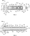
- FIG. 3 is a right side elevational view of the fastener assembly of FIG. 2 ;
- FIG. 4 is a cross-sectional view taken along lines 4 - 4 of FIG. 3 ;
- FIG. 5 is an enlarged view of a section of FIG. 3 ;
- FIG. 6 is an enlarged view of a section of FIG. 4 ;
- FIG. 7 is a front elevational view of the fastener assembly of FIG. 2 ;
- FIG. 8 is a right side elevational view of the rivet body of FIG. 1 ;
- FIG. 9 is a cross-sectional view taken along lines 9 - 9 of FIG. 8 ;
- FIG. 10 is a rear elevational view of the rivet body of FIG. 8 ;
- FIG. 11 depicts the fastener assembly of FIG. 3 in a second, assembled configuration
- FIG. 12 is a cross-sectional view taken along lines 12 - 12 of FIG. 11 ;
- FIG. 13 is a front elevational view of the fastener assembly of FIG. 11 ;
- FIG. 14 illustrates the fastener assembly of FIG. 11 mated with first and second components.
- Certain embodiments of the present disclosure provide a fastener assembly configured to engage and secure a plurality of components together, e.g., a first component and a second component. Further embodiments provide a fastener assembly configured to transition between operational states by axial rotation and, more particularly, axial rotation of a component of the fastener assembly. Various embodiments also provide a fastener assembly configured to engage and secure components having varying thicknesses, as well as a fastener assembly configured to have a plurality of operational or fastening states.
- FIGS. 1-14 depict a fastener assembly 100 , according to an aspect of the present disclosure, having a pin 102 and a rivet body 104 . More particularly, FIG. 1 depicts the fastener assembly 100 in an unassembled or non-operational configuration, FIGS. 2-7 depict the fastener assembly 100 in a first assembled or operational configuration, and FIGS. 11-13 depict the fastener assembly 100 in a second assembled or operational configuration. With reference to FIG. 14 , the fastener assembly 100 is shown engaged and secured to a first component and a second component, as will be further discussed herein. As will also be further discussed herein, although the fastener assembly 100 is shown in only two assembled or operational states, the fastener assembly 100 may have a plurality of other operational states.
- the pin 102 includes a head 106 and a shaft 108 extending longitudinally therefrom.
- the head 106 includes an upper portion 110 and a lower portion 112 , and in the present embodiment, the upper portion 110 is at least partially defined by a plurality of flat walls 114 and a top surface 116 .
- the lower portion 112 includes a rim 118 located at a bottom surface 120 of the head 106 .
- the upper portion 110 includes six walls 114 , which may be generally characterized as a hex screw drive.
- a user may rotate the head 106 of the pin 102 and, by extension, the shaft 108 of the pin 102 during use.
- a user may rotate the head 106 of the pin 102 using a wrench.
- the head 106 may utilize other configurations.
- a greater or fewer number of walls 114 may be provided.
- the upper portion 110 may comprise three walls, or four walls, or five walls, or eight walls, or ten walls.
- any number of equidistantly spaced walls may be provided that allow for the rotation of the upper portion 110 by an applied torque.
- the upper portion 110 may comprise other screw drives known in the art, such as a slotted drive (e.g., a slot or cross drive), a cruciform drive (e.g., a phillips or frearson drive), an internal drive (e.g., a square or hex drive), a hexalobular drive (e.g., a torx or polydrive), a three-pointed drive, or a special drive.
- a slotted drive e.g., a slot or cross drive
- a cruciform drive e.g., a phillips or frearson drive
- an internal drive e.g., a square or hex drive
- a hexalobular drive e.g., a torx or polydrive
- a three-pointed drive e.g., a special drive.
- the head 106 of the pin 102 is configured such that a user may apply a rotational force to the pin 102
- the desired structure will allow for rotation of the head 106 and the accompanying shaft 108 .
- Such rotation allows for one or more engagement features 122 , e.g., threading in the present embodiment, to engage portions of the rivet body 104 , as will be described in greater detail below.
- the rivet body 104 includes a collar 124 .
- the collar 124 of the present embodiment includes a generally annular configuration, i.e., a circular outer geometry with an opening 126 therethrough. However, other outer geometries are contemplated, e.g., a square, rectangle, oval, or any other shape.
- the collar 124 includes a bottom surface 128 , which may be generally flat and perpendicular to the axis 4 - 4 (see FIG. 3 ).
- a sidewall 130 also extends between the bottom surface 128 and a beveled surface 132 . In other embodiments, the surface 132 may take other linear forms, may be curvilinear, or may be a combination of both.
- a groove 134 is provided within the collar 124 and is defined by one or more walls.
- the groove 134 is defined by a wall 136 , which is generally concave, and includes a projection 137 extending therefrom (see FIGS. 4 and 6 ).
- the wall 136 (or walls) may take other forms as may be contemplated by those of skill in the art.
- the wall 136 may have a planar or V-shaped profile.
- the opening 126 may be centered within the wall 136 and may be concentric with the axis A-A (see FIG. 1 ).
- a receiving column 138 extends below the bottom surface 128 of the rivet body 104 and includes an interior channel 140 , which is in communication with the opening 126 (see FIGS. 1, 4, and 9 ).
- the interior channel 140 further extends to a second opening 142 on a side of the rivet body 104 that is opposite the opening 126 .
- the opening 126 , the interior channel 140 , and the second opening 142 are concentrically arranged or aligned. For instance, as shown in FIG. 1 , the opening 126 , the interior channel 140 , and the second opening all extend about the axis A-A.
- the receiving column 138 may include a first set of legs 150 with radial gaps 152 therebetween, and a second set of legs 154 with radial gaps 156 therebetween.
- the first set of legs 150 are longer than the second set of legs 154 .
- the first set of legs 150 are at least 1.25 times longer than the second set of legs 154 , or at least 1.5 times longer than the second set of legs 154 , or at least 2 times longer than the second set of legs 154 .
- the intermediate annular rim 158 may include one or more recessed surfaces 164 (see FIG. 5 ) positioned between the first set of legs 150 and the second set of legs 154 .
- the first set of legs 150 may each, individually, include a flexible bridge or intermediate section 166 having a cut-out section or notch 168 that is coextensive with the radial gaps 152 .
- the second set of legs 154 may also include a flexible bridge or intermediate section 170 with one or more notches 172 that are coextensive with the radial gaps 156 .
- the flexible intermediate sections 166 , 170 of the first set of legs 150 and the second set of legs 154 allow the legs 150 , 154 to flex outwardly during operational use, as will be further discussed herein.
- the receiving column 138 also includes one or more radial protrusions 180 on an interior surface 182 of the receiving column 138 .
- the rivet body 104 and the receiving column 138 thereof, includes four radial protrusions 180 evenly spaced around a circumference of the interior surface 182 of the rivet body 104 (see FIGS. 9 and 10 ).
- the radial protrusions 180 are adjacent the lower exterior edge 162 and offset relative to one another, such that some radial protrusions 180 are closer to the lower exterior edge 162 compared to the other radial protrusions 180 .
- the pin 102 may be positioned within the rivet body 104 by inserting a tip 184 of the pin 102 into the opening 126 of the collar 124 .
- surfaces defining the groove 134 such as the wall 136 , may provide a guiding function to align the tip 184 within the opening 126 so that it may be inserted into the interior channel 140 of the receiving column 138 .
- the pin 102 may be inserted into the rivet body 104 until the rim 118 of the head 106 (or otherwise the bottom surface 120 ) is disposed adjacent the projection 137 of the wall 136 .
- the rim 118 of the head 106 (or otherwise the bottom surface 120 ) is juxtaposed with the projection 137 (see FIG. 6 ).
- the upper portion 110 of the pin 102 includes a screw drive, which is depicted as a hex screw drive in the present embodiment.
- a tool may cooperate with the upper portion 110 to rotate the pin 102 during use.
- the projection 137 may function as a washer feature.
- rotation of the pin 102 is effected by the radial protrusions 180 rotationally engaging with the engagement features 122 , which are shown as threads in the present embodiment.
- rotation of the upper portion 110 of the pin 102 causes the radial protrusions 180 to travel along the engagement features 122 , to allow for the longitudinal translation of the lower annular rim 160 toward the head 106 .
- Such movement also allows for the flexible intermediate section 166 and the flexible intermediate section 170 to flex outwardly, as shown in FIGS. 11-13 .
- the notches 168 and the notches 172 also function to control rotation or prevent rotation of the rivet body 104 .
- the notch 168 may redirect a force applied to the intermediate section 166 toward a rigid portion of the first set of legs 150 , e.g., a portion of the first set of legs 150 that is not flexible.
- the pin 102 also includes a relief portion 188 , e.g., a portion without engagement features 122 or threading, which prevents over rotation of the rivet body 104 . More particularly, once the radial protrusions 180 of the rivet body 104 align with the relief portion 188 , rotation of the rivet body 104 ceases.
- a relief portion 188 e.g., a portion without engagement features 122 or threading
- the cooperation between the radial protrusions 180 of the rivet body 104 and the engagement features 122 of the pin 102 also improves the retention strength of the fastener assembly 100 . More particularly, whether the fastener assembly 100 is in a first assembled state (such as that shown in FIGS. 3 and 4 ) or a second assembled state (such as that shown in FIGS. 11 and 12 ), one or more of the radial protrusions 180 are seated on or engaged with the engagement features 122 . As such, the radial protrusions 180 and the engagement features 122 prevent axial or longitudinal movement of the lower annular rim 160 toward the tip 184 of the pin 102 when a large load is applied to the first set of legs 150 and/or the second set of legs 154 .
- a user may first insert the pin 102 into the rivet body 104 as previously noted above.
- the pin 102 and the rivet body 104 are then rotationally engaged by causing the radial protrusions 180 and the engagement features 122 to mate with one another, thus providing the fastener assembly 100 in a first, assembled state as depicted in FIGS. 2-7 .
- a user may insert the assembled faster assembly 100 through one or more panels.
- the fastener assembly 100 may be inserted into a first and second hole (not shown) of a first panel 190 and a second panel 192 , respectively.
- the fastener assembly 100 may be positioned through the holes of the first and second panels 190 , 192 so that the rim 118 or bottom surface 128 is proximate and in contact or engaged with an outside surface 194 of the first panel 190 .
- a user rotates the upper portion 110 of the pin 102 .
- the lower annular rim 160 rides longitudinally along the engagement features 122 .
- the flexible intermediate section 166 and the flexible intermediate section 170 to flex outwardly.
- a user may rotate the upper portion 110 until a first side 196 of the first set of legs 150 contacts a rear side 198 of the second panel 192 .
- the second set of legs 154 may flex outwardly so that they are proximate the first set of legs 150 and provide support therefor.
- the second set of legs 154 may be composed of a stiffer or more robust material than the first set of legs 150 .
- the lower annular rim 160 rides longitudinally along the engagement features 122 upon rotation of the lower portion 112 of the pin 102 .
- a distance between the bottom surface 120 of the lower portion 112 of the pin 102 and the bottom surface 128 of the collar 124 of the rivet body 104 remains constant.
- the distance between the bottom surface 120 of the lower portion 112 of the pin 102 and the bottom surface 128 of the collar 124 of the rivet body 104 is the same.
- the bottom surface 120 of the lower portion 112 of the pin 102 is in contact with the projection 137 of the rivet body 104 throughout axial rotation of the pin 102 relative to the rivet body 104 .
- a distance between the bottom surface 120 of the lower portion 112 of the pin 102 and the lower exterior edge 162 of the rivet body 104 decreases upon rotation of the pin 102 relative to the rivet body 104 .
- a distance between the tip 184 of the pin 102 and the lower exterior edge 162 of the rivet body 104 increases upon rotation of the pin 102
- a distance between the tip 184 of the pin 102 and the bottom surface 128 of the collar 124 of the rivet body 104 remains constant upon rotation of the pin 102 .
- the fastener assembly 100 is only shown in a first assembled state (e.g., see FIG. 3 ) and a second assembled state (e.g., see FIG. 11 ), it is contemplated that axial rotation of the pin 102 relative to the rivet body 104 may cease at any time while the fastener assembly 100 is transitioning between the first assembled state and the second assembled state. For example, axial rotation of the pin 102 relative to the rivet body 104 may cease halfway through the transition between the first assembled state shown in FIG. 3 and the second assembled state shown in FIG. 11 . In this particular embodiment, the first set of legs 150 and the second set of legs 154 would only partially collapse.
- the fastener assembly 100 may have a plurality of assembled states, which provides variability during use of the fastener assembly 100 .
- this variability allows the fastener assembly 100 to secure components having variable width. For example, if the fastener assembly 100 is used to secure components together having a combined width that is small, the pin 102 may be axially rotated such that the first set of legs 150 and the second set of legs 154 fully collapse. On the other hand, if the fastener assembly 100 is used to secure components together having a combined width that is large, the pin 102 may be axially rotated to a lesser degree such that the first set of legs and/or the second set of legs 154 only partially collapse.
- the pin 102 of the fastener assembly 100 may also be rotated in an opposite direction. Rotation of the pin 102 in an opposite direction may cause the lower annular rim 160 , and the lower exterior edge 162 thereof, to move toward the tip 184 of the pin 102 and away from the bottom surface 128 of the rivet body 104 . In effect, rotation of the pin 102 in an opposite direction allows the fastener assembly 100 to transition back to the first assembled state (see FIG. 3 ) from the second assembled state (see FIG. 11 ). During use, the pin 102 of the fastener assembly 100 may be rotated in an opposite direction when a user desires to remove the fastener assembly 100 from components (e.g., first component 190 and second component 192 ), for example.
- components e.g., first component 190 and second component 192
- the intermediate annular rim 158 includes the recessed surfaces 164 , which may also provide energy support for the fastener assembly 100 . More particularly, once the fastener assembly 100 is in the second, assembled state (as shown in FIG. 14 ), the recessed surfaces 164 may provide a flexibility to the fastener assembly 100 once a force is exerted onto the fastener assembly 100 , the first panel 190 , and/or the second panel 192 . As best shown in FIG. 8 , the lower annular rim 160 may also include one or more recessed surfaces 200 and an upper portion of the receiving column 138 may also include one or more recessed surfaces 202 .
- the recessed surfaces may be positioned around an outer circumference of the receiving column 138 , proximate the first set of legs 150 , and/or proximate the second set of legs 154 .
- the interaction between the radial protrusions 180 and the engagement features 122 may provide added support or stability to the fastener assembly 100 .
- the pin 102 and the rivet body 104 may be positionally locked relative to one another and movement of the pin 102 through the receiving column 138 is only possible upon rotation of the upper portion 110 of the pin 102 .
Landscapes
- Engineering & Computer Science (AREA)
- General Engineering & Computer Science (AREA)
- Mechanical Engineering (AREA)
- Insertion Pins And Rivets (AREA)
Abstract
Description
Claims (17)
Priority Applications (2)
| Application Number | Priority Date | Filing Date | Title |
|---|---|---|---|
| US16/575,685 US11268557B2 (en) | 2018-10-10 | 2019-09-19 | Rivet fastener assembly and method of use thereof |
| CN201910970975.XA CN111022467B (en) | 2018-10-10 | 2019-10-09 | Rivet fastener assembly and method of using same |
Applications Claiming Priority (2)
| Application Number | Priority Date | Filing Date | Title |
|---|---|---|---|
| US201862744000P | 2018-10-10 | 2018-10-10 | |
| US16/575,685 US11268557B2 (en) | 2018-10-10 | 2019-09-19 | Rivet fastener assembly and method of use thereof |
Publications (2)
| Publication Number | Publication Date |
|---|---|
| US20200116184A1 US20200116184A1 (en) | 2020-04-16 |
| US11268557B2 true US11268557B2 (en) | 2022-03-08 |
Family
ID=70158951
Family Applications (1)
| Application Number | Title | Priority Date | Filing Date |
|---|---|---|---|
| US16/575,685 Active 2040-01-04 US11268557B2 (en) | 2018-10-10 | 2019-09-19 | Rivet fastener assembly and method of use thereof |
Country Status (2)
| Country | Link |
|---|---|
| US (1) | US11268557B2 (en) |
| CN (1) | CN111022467B (en) |
Cited By (1)
| Publication number | Priority date | Publication date | Assignee | Title |
|---|---|---|---|---|
| USD1056681S1 (en) * | 2023-04-10 | 2025-01-07 | Thuma Inc. | Anti-tip device |
Families Citing this family (5)
| Publication number | Priority date | Publication date | Assignee | Title |
|---|---|---|---|---|
| KR20190039711A (en) | 2016-08-12 | 2019-04-15 | 일리노이즈 툴 워크스 인코포레이티드 | Rivet fastener assembly |
| DE102019101078A1 (en) | 2018-01-16 | 2019-07-18 | Illinois Tool Works Inc. | NIET FASTENER ELEMENT DESIGN AND METHOD OF USE THEREOF |
| US11268557B2 (en) | 2018-10-10 | 2022-03-08 | Illinois Tool Works Inc. | Rivet fastener assembly and method of use thereof |
| DE102020131713B4 (en) * | 2020-11-30 | 2022-06-15 | Protechna S.A. | bung plug closure |
| US20230332635A1 (en) * | 2022-04-18 | 2023-10-19 | Robert Tzorany | Drywall Sleeve Anchor |
Citations (66)
| Publication number | Priority date | Publication date | Assignee | Title |
|---|---|---|---|---|
| US519172A (en) * | 1894-05-01 | Half to timothy j | ||
| US1161155A (en) * | 1913-08-02 | 1915-11-23 | Henry B Newhall | Combined expansion and toggle bolt and parts thereof. |
| US2324142A (en) | 1941-04-03 | 1943-07-13 | Rolyan Corp | Rivet and method of making same |
| US2964989A (en) * | 1948-07-01 | 1960-12-20 | Croessant Machine Works Inc | Expanding screw anchor |
| US3136203A (en) * | 1960-11-29 | 1964-06-09 | Gen Dynamics Corp | Blind rivet having means for retaining the expansion bolt |
| US3236143A (en) | 1959-05-15 | 1966-02-22 | Hi Shear Corp | Blind fastening device with collapsible tube |
| US3279304A (en) | 1965-07-07 | 1966-10-18 | Nat Screw & Mfg Company | High strength blind fastener |
| US3512448A (en) * | 1966-02-25 | 1970-05-19 | Aerpat Ag | Blind fastener |
| US3789727A (en) | 1972-06-05 | 1974-02-05 | Eaton Corp | Fastener |
| US3858479A (en) | 1973-09-14 | 1975-01-07 | Hi Shear Corp | Blind fastener set by rotary stud having threads of opposite hand |
| US3888156A (en) * | 1974-03-29 | 1975-06-10 | Raoul Fima | Anchor bolt construction |
| US3984132A (en) * | 1975-02-27 | 1976-10-05 | The Weatherhead Company | Bulkhead fitting |
| US4211145A (en) | 1974-09-04 | 1980-07-08 | Mecano-Simmonds Gmbh | Blind rivet |
| US4285265A (en) | 1978-07-14 | 1981-08-25 | Messerschmitt-Boelkow-Blohm Gesellschaft Mit Beschraenkter Haftung | Tacking rivet |
| US4475856A (en) * | 1979-12-21 | 1984-10-09 | Telefonaktiebolaget L M Ericsson | Expansion screw with an expansion sleeve having an outer cylindrical surface and regions of greater and lesser wall thickness |
| US4541761A (en) | 1983-09-26 | 1985-09-17 | Usm Corporation | Easily removed blind rivet |
| US4556351A (en) | 1982-04-26 | 1985-12-03 | Phillips Plastics Corporation | Expansion rivet assembly |
| US4585382A (en) | 1983-12-01 | 1986-04-29 | Usm Corporation | Easily removable rivet with tab |
| US4610587A (en) * | 1983-12-27 | 1986-09-09 | Phillips Plastics Corporation | Reusable two-piece fastener |
| US4639175A (en) | 1984-05-15 | 1987-01-27 | Phillips Plastics Corp. | Self-sealing expansion rivet assembly |
| US4642009A (en) * | 1984-07-21 | 1987-02-10 | Artur Fischer | Wall plug |
| GB2185081A (en) | 1986-01-07 | 1987-07-08 | Futters | Screw anchor |
| US4708553A (en) | 1983-09-29 | 1987-11-24 | Usm Corporation | Large secondary head rivet |
| US4863325A (en) | 1982-09-28 | 1989-09-05 | Huck Manufacturing Company | Two piece blind fastener with lock spindle construction |
| US4875815A (en) | 1988-03-17 | 1989-10-24 | The B. F. Goodrich Company | Blind fastener |
| US4890966A (en) * | 1987-08-07 | 1990-01-02 | Nifco, Inc. | Securing clip |
| US5018919A (en) * | 1989-04-15 | 1991-05-28 | Bergwerksverband Gmbh | Combined rigid profile and stretching roof bolt with expansion element |
| US5205688A (en) | 1989-01-11 | 1993-04-27 | Thorsman & Co Aktiebolag | Deformable plug of a wall fastener |
| US5244324A (en) | 1992-08-18 | 1993-09-14 | Dry Dock Industries, Inc. | Anchoring retainer for threaded fastener |
| EP0691479A1 (en) | 1994-07-05 | 1996-01-10 | Emhart Inc. | Blind rivet assembly |
| US5690454A (en) * | 1992-11-23 | 1997-11-25 | Dry Dock Industries, Inc. | Anchoring retainer for threaded fasteners |
| US5725341A (en) * | 1997-01-08 | 1998-03-10 | Hofmeister; Oskar | Self fusing fastener |
| US20020154963A1 (en) | 1999-12-08 | 2002-10-24 | Gary Jennings | Closed-end blind rivet with a crimped shank and method of manufacture thereof |
| US6551040B1 (en) | 2001-12-27 | 2003-04-22 | Huck International, Inc. | Blind fastener with a blind side head having a clamp support and lock section |
| US6609866B2 (en) * | 2001-09-12 | 2003-08-26 | Joker Industrial Co., Ltd. | Expandable metal body for an expansion bolt |
| US6719509B1 (en) * | 2002-10-04 | 2004-04-13 | Joker Ind Co Ltd | Expansion screw |
| US6746191B2 (en) * | 2001-02-06 | 2004-06-08 | Illinois Tool Works Inc. | Reusable rivet |
| US6761520B1 (en) | 2003-05-09 | 2004-07-13 | Pem Management, Inc. | Clinch-type blind nut |
| CN1521412A (en) | 2003-02-11 | 2004-08-18 | Ejot��������˾ | Plastic nut for mounting on a component having a penetration |
| US6835038B2 (en) * | 2001-07-10 | 2004-12-28 | Aparellaje Electrico, S.L. | Wall plug |
| US20050013678A1 (en) | 2003-07-16 | 2005-01-20 | Smith Daniel R. | Three part blind fastener |
| GB2412417A (en) | 2004-03-27 | 2005-09-28 | Joker Ind Co Ltd | An expansion bolt |
| US6969220B2 (en) * | 2003-04-24 | 2005-11-29 | Black & Decker Inc. | Wall anchor for a screw, and assembly constituted by such a wall anchor and a screw |
| US20060182512A1 (en) | 2005-02-11 | 2006-08-17 | Williams Michael K | Frangible blind rivet |
| EP1728569A1 (en) | 2005-05-31 | 2006-12-06 | Newfrey LLC | A blind rivet, removal system and related method |
| US20070059120A1 (en) | 2005-09-15 | 2007-03-15 | Vigliotti Daniel P | Blind rivet and method |
| US7621950B1 (en) * | 1999-01-27 | 2009-11-24 | Kyphon Sarl | Expandable intervertebral spacer |
| CN201428676Y (en) | 2009-06-29 | 2010-03-24 | 周志灿 | Enclosed self-plugging rivet |
| WO2011094056A1 (en) | 2010-01-27 | 2011-08-04 | Illinois Tool Works Inc. | Fastener assembly |
| DE102010002847A1 (en) | 2010-03-15 | 2011-09-15 | Newfrey Llc | Blind rivet with a plastic rivet body |
| CN202165364U (en) | 2011-08-01 | 2012-03-14 | 王涛 | Conveniently-dismounted special rivet for battery cover plate |
| DE102011106436A1 (en) | 2011-07-04 | 2013-01-10 | Illinois Tool Works Inc. | Device for fixing component to another component, particularly automotive components, such as covering parts, has fixing sleeve with sleeve section, where sleeve head is formed to lie at sleeve section at upper surface of component |
| DE202013005407U1 (en) | 2013-06-14 | 2013-06-28 | Alfred Stelz | Variable fixing anchor with right and left hand thread, and two axially variably positionable expansion bodies, each with one right and left hand thread |
| US8602703B1 (en) * | 2010-02-24 | 2013-12-10 | Michael Rich | Anchor for wall and other structures |
| US8728160B2 (en) * | 1999-01-27 | 2014-05-20 | Warsaw Orthopedic, Inc. | Expandable intervertebral spacer |
| US20140377030A1 (en) | 2013-03-15 | 2014-12-25 | Sps Technologies, Llc | Blind, bulbing, tacking rivet and method of installation |
| US8931988B2 (en) * | 2008-03-24 | 2015-01-13 | Nifco Inc. | Screw grommet |
| US9062703B2 (en) * | 2011-09-15 | 2015-06-23 | Newfrey Llc | Blind rivet and workpiece arrangement |
| DE102014104539A1 (en) | 2014-03-31 | 2015-10-01 | Newfrey Llc | Method and device for releasing a blind rivet connection |
| US9309906B2 (en) * | 2013-11-19 | 2016-04-12 | Fu-Chuan Hsu | Self-drilling expansion fastener and method of forming same |
| US9453524B2 (en) * | 2012-03-29 | 2016-09-27 | Wingit Innovations, Llc | Mechanically biased cantilever fastener assembly |
| WO2018031168A1 (en) | 2016-08-12 | 2018-02-15 | Illinois Tool Works Inc. | Rivet fastener assemblies |
| US20180238371A1 (en) | 2015-10-27 | 2018-08-23 | A. Raymond Et Cie | Self-piercing rivet with high mechanical strength against tearing out and shearing |
| US10215210B2 (en) * | 2015-11-17 | 2019-02-26 | Arconic Inc. | Blind fastener |
| US20190219086A1 (en) * | 2018-01-16 | 2019-07-18 | Illinois Tool Works Inc. | Rivet fastener assembly and method of use thereof |
| US20200116184A1 (en) | 2018-10-10 | 2020-04-16 | Illinois Tool Works Inc. | Rivet fastener assembly and method of use thereof |
Family Cites Families (3)
| Publication number | Priority date | Publication date | Assignee | Title |
|---|---|---|---|---|
| MY105063A (en) * | 1988-11-18 | 1994-07-30 | Industrial Pipe Systems Pty Ltd | Panel anchor. |
| US20140180428A1 (en) * | 2012-12-21 | 2014-06-26 | Wright Medical Technology, Inc. | Percutaneous expanding hammertoe implant |
| CN207261407U (en) * | 2017-10-16 | 2018-04-20 | 李忠玉 | A kind of multi-functional crab-bolt |
-
2019
- 2019-09-19 US US16/575,685 patent/US11268557B2/en active Active
- 2019-10-09 CN CN201910970975.XA patent/CN111022467B/en active Active
Patent Citations (69)
| Publication number | Priority date | Publication date | Assignee | Title |
|---|---|---|---|---|
| US519172A (en) * | 1894-05-01 | Half to timothy j | ||
| US1161155A (en) * | 1913-08-02 | 1915-11-23 | Henry B Newhall | Combined expansion and toggle bolt and parts thereof. |
| US2324142A (en) | 1941-04-03 | 1943-07-13 | Rolyan Corp | Rivet and method of making same |
| US2964989A (en) * | 1948-07-01 | 1960-12-20 | Croessant Machine Works Inc | Expanding screw anchor |
| US3236143A (en) | 1959-05-15 | 1966-02-22 | Hi Shear Corp | Blind fastening device with collapsible tube |
| US3136203A (en) * | 1960-11-29 | 1964-06-09 | Gen Dynamics Corp | Blind rivet having means for retaining the expansion bolt |
| US3279304A (en) | 1965-07-07 | 1966-10-18 | Nat Screw & Mfg Company | High strength blind fastener |
| US3512448A (en) * | 1966-02-25 | 1970-05-19 | Aerpat Ag | Blind fastener |
| US3789727A (en) | 1972-06-05 | 1974-02-05 | Eaton Corp | Fastener |
| US3858479A (en) | 1973-09-14 | 1975-01-07 | Hi Shear Corp | Blind fastener set by rotary stud having threads of opposite hand |
| US3888156A (en) * | 1974-03-29 | 1975-06-10 | Raoul Fima | Anchor bolt construction |
| US4211145A (en) | 1974-09-04 | 1980-07-08 | Mecano-Simmonds Gmbh | Blind rivet |
| US3984132A (en) * | 1975-02-27 | 1976-10-05 | The Weatherhead Company | Bulkhead fitting |
| US4285265A (en) | 1978-07-14 | 1981-08-25 | Messerschmitt-Boelkow-Blohm Gesellschaft Mit Beschraenkter Haftung | Tacking rivet |
| US4475856A (en) * | 1979-12-21 | 1984-10-09 | Telefonaktiebolaget L M Ericsson | Expansion screw with an expansion sleeve having an outer cylindrical surface and regions of greater and lesser wall thickness |
| US4556351A (en) | 1982-04-26 | 1985-12-03 | Phillips Plastics Corporation | Expansion rivet assembly |
| US4863325A (en) | 1982-09-28 | 1989-09-05 | Huck Manufacturing Company | Two piece blind fastener with lock spindle construction |
| US4541761A (en) | 1983-09-26 | 1985-09-17 | Usm Corporation | Easily removed blind rivet |
| US4708553A (en) | 1983-09-29 | 1987-11-24 | Usm Corporation | Large secondary head rivet |
| US4585382A (en) | 1983-12-01 | 1986-04-29 | Usm Corporation | Easily removable rivet with tab |
| US4610587A (en) * | 1983-12-27 | 1986-09-09 | Phillips Plastics Corporation | Reusable two-piece fastener |
| US4639175A (en) | 1984-05-15 | 1987-01-27 | Phillips Plastics Corp. | Self-sealing expansion rivet assembly |
| US4642009A (en) * | 1984-07-21 | 1987-02-10 | Artur Fischer | Wall plug |
| GB2185081A (en) | 1986-01-07 | 1987-07-08 | Futters | Screw anchor |
| US4890966A (en) * | 1987-08-07 | 1990-01-02 | Nifco, Inc. | Securing clip |
| US4875815A (en) | 1988-03-17 | 1989-10-24 | The B. F. Goodrich Company | Blind fastener |
| US5205688A (en) | 1989-01-11 | 1993-04-27 | Thorsman & Co Aktiebolag | Deformable plug of a wall fastener |
| US5018919A (en) * | 1989-04-15 | 1991-05-28 | Bergwerksverband Gmbh | Combined rigid profile and stretching roof bolt with expansion element |
| US5244324A (en) | 1992-08-18 | 1993-09-14 | Dry Dock Industries, Inc. | Anchoring retainer for threaded fastener |
| US5690454A (en) * | 1992-11-23 | 1997-11-25 | Dry Dock Industries, Inc. | Anchoring retainer for threaded fasteners |
| EP0691479A1 (en) | 1994-07-05 | 1996-01-10 | Emhart Inc. | Blind rivet assembly |
| US5725341A (en) * | 1997-01-08 | 1998-03-10 | Hofmeister; Oskar | Self fusing fastener |
| US8728160B2 (en) * | 1999-01-27 | 2014-05-20 | Warsaw Orthopedic, Inc. | Expandable intervertebral spacer |
| US7621950B1 (en) * | 1999-01-27 | 2009-11-24 | Kyphon Sarl | Expandable intervertebral spacer |
| US20020154963A1 (en) | 1999-12-08 | 2002-10-24 | Gary Jennings | Closed-end blind rivet with a crimped shank and method of manufacture thereof |
| US6746191B2 (en) * | 2001-02-06 | 2004-06-08 | Illinois Tool Works Inc. | Reusable rivet |
| US6835038B2 (en) * | 2001-07-10 | 2004-12-28 | Aparellaje Electrico, S.L. | Wall plug |
| US6609866B2 (en) * | 2001-09-12 | 2003-08-26 | Joker Industrial Co., Ltd. | Expandable metal body for an expansion bolt |
| US6551040B1 (en) | 2001-12-27 | 2003-04-22 | Huck International, Inc. | Blind fastener with a blind side head having a clamp support and lock section |
| US6719509B1 (en) * | 2002-10-04 | 2004-04-13 | Joker Ind Co Ltd | Expansion screw |
| CN1521412A (en) | 2003-02-11 | 2004-08-18 | Ejot��������˾ | Plastic nut for mounting on a component having a penetration |
| US6969220B2 (en) * | 2003-04-24 | 2005-11-29 | Black & Decker Inc. | Wall anchor for a screw, and assembly constituted by such a wall anchor and a screw |
| US6761520B1 (en) | 2003-05-09 | 2004-07-13 | Pem Management, Inc. | Clinch-type blind nut |
| US20050013678A1 (en) | 2003-07-16 | 2005-01-20 | Smith Daniel R. | Three part blind fastener |
| GB2412417A (en) | 2004-03-27 | 2005-09-28 | Joker Ind Co Ltd | An expansion bolt |
| US20060182512A1 (en) | 2005-02-11 | 2006-08-17 | Williams Michael K | Frangible blind rivet |
| EP1728569A1 (en) | 2005-05-31 | 2006-12-06 | Newfrey LLC | A blind rivet, removal system and related method |
| US20070059120A1 (en) | 2005-09-15 | 2007-03-15 | Vigliotti Daniel P | Blind rivet and method |
| US7887273B2 (en) | 2005-09-15 | 2011-02-15 | Newfrey Llc | Blind rivet and method |
| US8931988B2 (en) * | 2008-03-24 | 2015-01-13 | Nifco Inc. | Screw grommet |
| CN201428676Y (en) | 2009-06-29 | 2010-03-24 | 周志灿 | Enclosed self-plugging rivet |
| WO2011094056A1 (en) | 2010-01-27 | 2011-08-04 | Illinois Tool Works Inc. | Fastener assembly |
| US8602703B1 (en) * | 2010-02-24 | 2013-12-10 | Michael Rich | Anchor for wall and other structures |
| US20130243542A1 (en) | 2010-03-15 | 2013-09-19 | Newfrey Llc | Blind rivet with a plastic rivet body |
| DE102010002847A1 (en) | 2010-03-15 | 2011-09-15 | Newfrey Llc | Blind rivet with a plastic rivet body |
| DE102011106436A1 (en) | 2011-07-04 | 2013-01-10 | Illinois Tool Works Inc. | Device for fixing component to another component, particularly automotive components, such as covering parts, has fixing sleeve with sleeve section, where sleeve head is formed to lie at sleeve section at upper surface of component |
| CN202165364U (en) | 2011-08-01 | 2012-03-14 | 王涛 | Conveniently-dismounted special rivet for battery cover plate |
| US9062703B2 (en) * | 2011-09-15 | 2015-06-23 | Newfrey Llc | Blind rivet and workpiece arrangement |
| US9453524B2 (en) * | 2012-03-29 | 2016-09-27 | Wingit Innovations, Llc | Mechanically biased cantilever fastener assembly |
| US20140377030A1 (en) | 2013-03-15 | 2014-12-25 | Sps Technologies, Llc | Blind, bulbing, tacking rivet and method of installation |
| DE202013005407U1 (en) | 2013-06-14 | 2013-06-28 | Alfred Stelz | Variable fixing anchor with right and left hand thread, and two axially variably positionable expansion bodies, each with one right and left hand thread |
| US9309906B2 (en) * | 2013-11-19 | 2016-04-12 | Fu-Chuan Hsu | Self-drilling expansion fastener and method of forming same |
| DE102014104539A1 (en) | 2014-03-31 | 2015-10-01 | Newfrey Llc | Method and device for releasing a blind rivet connection |
| US20180238371A1 (en) | 2015-10-27 | 2018-08-23 | A. Raymond Et Cie | Self-piercing rivet with high mechanical strength against tearing out and shearing |
| US10215210B2 (en) * | 2015-11-17 | 2019-02-26 | Arconic Inc. | Blind fastener |
| WO2018031168A1 (en) | 2016-08-12 | 2018-02-15 | Illinois Tool Works Inc. | Rivet fastener assemblies |
| US20190264722A1 (en) | 2016-08-12 | 2019-08-29 | Illinois Tool Works Inc. | Rivet fastener assemblies |
| US20190219086A1 (en) * | 2018-01-16 | 2019-07-18 | Illinois Tool Works Inc. | Rivet fastener assembly and method of use thereof |
| US20200116184A1 (en) | 2018-10-10 | 2020-04-16 | Illinois Tool Works Inc. | Rivet fastener assembly and method of use thereof |
Non-Patent Citations (3)
| Title |
|---|
| Examination Report for German Patent Application No. 10 2019 101 078.0, dated Dec. 1, 2020 (22 pages) English translation included). |
| First Office Action from corresponding Chinese Patent Application No. 201780048642.0, dated May 22, 2020 (16 pages) (English translation included). |
| International Search Report for PCT/US2017/041636, dated Oct. 5, 2017. (11 pages). |
Cited By (1)
| Publication number | Priority date | Publication date | Assignee | Title |
|---|---|---|---|---|
| USD1056681S1 (en) * | 2023-04-10 | 2025-01-07 | Thuma Inc. | Anti-tip device |
Also Published As
| Publication number | Publication date |
|---|---|
| CN111022467A (en) | 2020-04-17 |
| US20200116184A1 (en) | 2020-04-16 |
| CN111022467B (en) | 2023-02-28 |
Similar Documents
| Publication | Publication Date | Title |
|---|---|---|
| US11268557B2 (en) | Rivet fastener assembly and method of use thereof | |
| US5370484A (en) | Push rivet having unfastening means | |
| JP4860660B2 (en) | Improved drive socket design for holding and drive fasteners | |
| US5246322A (en) | Fastening element comprising a dowel-shaped sleeve | |
| US10344786B2 (en) | Quick fastener, method for connecting two components by means of the quick fastener and production method therefor | |
| US6161982A (en) | Assembly with a sealed coupler | |
| US6015251A (en) | Secure threaded fastener | |
| US20060127169A1 (en) | Threaded joining assembly with tolerances compensating means | |
| JPH09507099A (en) | Joint forming equipment | |
| CA2316609A1 (en) | Pushnut | |
| SK280303B6 (en) | SCREW AND TOOL WITH CONTROL ELEMENT | |
| US20100119325A1 (en) | Stud retaining fastener assembly | |
| EP3810939B1 (en) | Fastening clip assemblies | |
| EP3111804B1 (en) | Concealable connection device for furniture | |
| JP2736259B2 (en) | Joining equipment | |
| US20050019129A1 (en) | Joining assembly for joining a pair of structural members | |
| US20070043379A1 (en) | Bone screw/driver assembly and method | |
| KR20200034732A (en) | Cutting tool and cutting tool body with fixing member for fixing the coupling screw | |
| US20230250843A1 (en) | Tool attachment point with alignment aid | |
| US9249824B2 (en) | Locking nut for toilet seat | |
| US12385510B2 (en) | Tolerance compensation fastening assembly | |
| EA018490B1 (en) | Method for introduction of expanding sleeve into a soft material | |
| US4402116A (en) | Concealed interlocking fastener | |
| US20150198198A1 (en) | Locking nut for toilet seat | |
| CA2002847A1 (en) | Panel anchor |
Legal Events
| Date | Code | Title | Description |
|---|---|---|---|
| FEPP | Fee payment procedure |
Free format text: ENTITY STATUS SET TO UNDISCOUNTED (ORIGINAL EVENT CODE: BIG.); ENTITY STATUS OF PATENT OWNER: LARGE ENTITY |
|
| AS | Assignment |
Owner name: ILLINOIS TOOL WORKS INC., ILLINOIS Free format text: ASSIGNMENT OF ASSIGNORS INTEREST;ASSIGNOR:LEE, JOEL R.;REEL/FRAME:050893/0089 Effective date: 20190919 |
|
| STPP | Information on status: patent application and granting procedure in general |
Free format text: DOCKETED NEW CASE - READY FOR EXAMINATION |
|
| STPP | Information on status: patent application and granting procedure in general |
Free format text: NON FINAL ACTION MAILED |
|
| STPP | Information on status: patent application and granting procedure in general |
Free format text: RESPONSE TO NON-FINAL OFFICE ACTION ENTERED AND FORWARDED TO EXAMINER |
|
| STPP | Information on status: patent application and granting procedure in general |
Free format text: FINAL REJECTION MAILED |
|
| STPP | Information on status: patent application and granting procedure in general |
Free format text: RESPONSE AFTER FINAL ACTION FORWARDED TO EXAMINER |
|
| STPP | Information on status: patent application and granting procedure in general |
Free format text: ADVISORY ACTION MAILED |
|
| STPP | Information on status: patent application and granting procedure in general |
Free format text: NON FINAL ACTION MAILED |
|
| STPP | Information on status: patent application and granting procedure in general |
Free format text: FINAL REJECTION MAILED |
|
| STPP | Information on status: patent application and granting procedure in general |
Free format text: RESPONSE AFTER FINAL ACTION FORWARDED TO EXAMINER |
|
| STPP | Information on status: patent application and granting procedure in general |
Free format text: NOTICE OF ALLOWANCE MAILED -- APPLICATION RECEIVED IN OFFICE OF PUBLICATIONS |
|
| STPP | Information on status: patent application and granting procedure in general |
Free format text: NOTICE OF ALLOWANCE MAILED -- APPLICATION RECEIVED IN OFFICE OF PUBLICATIONS |
|
| STCF | Information on status: patent grant |
Free format text: PATENTED CASE |
|
| MAFP | Maintenance fee payment |
Free format text: PAYMENT OF MAINTENANCE FEE, 4TH YEAR, LARGE ENTITY (ORIGINAL EVENT CODE: M1551); ENTITY STATUS OF PATENT OWNER: LARGE ENTITY Year of fee payment: 4 |