US11267292B2 - Heavy-duty vehicle tire - Google Patents
Heavy-duty vehicle tire Download PDFInfo
- Publication number
- US11267292B2 US11267292B2 US16/091,890 US201716091890A US11267292B2 US 11267292 B2 US11267292 B2 US 11267292B2 US 201716091890 A US201716091890 A US 201716091890A US 11267292 B2 US11267292 B2 US 11267292B2
- Authority
- US
- United States
- Prior art keywords
- angle
- relief
- tire
- equal
- heavy vehicle
- Prior art date
- Legal status (The legal status is an assumption and is not a legal conclusion. Google has not performed a legal analysis and makes no representation as to the accuracy of the status listed.)
- Active, expires
Links
Images


Classifications
-
- B—PERFORMING OPERATIONS; TRANSPORTING
- B60—VEHICLES IN GENERAL
- B60C—VEHICLE TYRES; TYRE INFLATION; TYRE CHANGING; CONNECTING VALVES TO INFLATABLE ELASTIC BODIES IN GENERAL; DEVICES OR ARRANGEMENTS RELATED TO TYRES
- B60C11/00—Tyre tread bands; Tread patterns; Anti-skid inserts
- B60C11/03—Tread patterns
- B60C11/0306—Patterns comprising block rows or discontinuous ribs
- B60C11/0309—Patterns comprising block rows or discontinuous ribs further characterised by the groove cross-section
-
- B—PERFORMING OPERATIONS; TRANSPORTING
- B60—VEHICLES IN GENERAL
- B60C—VEHICLE TYRES; TYRE INFLATION; TYRE CHANGING; CONNECTING VALVES TO INFLATABLE ELASTIC BODIES IN GENERAL; DEVICES OR ARRANGEMENTS RELATED TO TYRES
- B60C11/00—Tyre tread bands; Tread patterns; Anti-skid inserts
- B60C11/03—Tread patterns
- B60C11/13—Tread patterns characterised by the groove cross-section, e.g. for buttressing or preventing stone-trapping
- B60C11/1307—Tread patterns characterised by the groove cross-section, e.g. for buttressing or preventing stone-trapping with special features of the groove walls
- B60C11/1323—Tread patterns characterised by the groove cross-section, e.g. for buttressing or preventing stone-trapping with special features of the groove walls asymmetric
-
- B—PERFORMING OPERATIONS; TRANSPORTING
- B60—VEHICLES IN GENERAL
- B60C—VEHICLE TYRES; TYRE INFLATION; TYRE CHANGING; CONNECTING VALVES TO INFLATABLE ELASTIC BODIES IN GENERAL; DEVICES OR ARRANGEMENTS RELATED TO TYRES
- B60C11/00—Tyre tread bands; Tread patterns; Anti-skid inserts
- B60C11/03—Tread patterns
- B60C11/0302—Tread patterns directional pattern, i.e. with main rolling direction
-
- B—PERFORMING OPERATIONS; TRANSPORTING
- B60—VEHICLES IN GENERAL
- B60C—VEHICLE TYRES; TYRE INFLATION; TYRE CHANGING; CONNECTING VALVES TO INFLATABLE ELASTIC BODIES IN GENERAL; DEVICES OR ARRANGEMENTS RELATED TO TYRES
- B60C11/00—Tyre tread bands; Tread patterns; Anti-skid inserts
- B60C11/03—Tread patterns
- B60C11/0304—Asymmetric patterns
-
- B—PERFORMING OPERATIONS; TRANSPORTING
- B60—VEHICLES IN GENERAL
- B60C—VEHICLE TYRES; TYRE INFLATION; TYRE CHANGING; CONNECTING VALVES TO INFLATABLE ELASTIC BODIES IN GENERAL; DEVICES OR ARRANGEMENTS RELATED TO TYRES
- B60C11/00—Tyre tread bands; Tread patterns; Anti-skid inserts
- B60C11/03—Tread patterns
- B60C11/11—Tread patterns in which the raised area of the pattern consists only of isolated elements, e.g. blocks
-
- B—PERFORMING OPERATIONS; TRANSPORTING
- B60—VEHICLES IN GENERAL
- B60C—VEHICLE TYRES; TYRE INFLATION; TYRE CHANGING; CONNECTING VALVES TO INFLATABLE ELASTIC BODIES IN GENERAL; DEVICES OR ARRANGEMENTS RELATED TO TYRES
- B60C2200/00—Tyres specially adapted for particular applications
- B60C2200/06—Tyres specially adapted for particular applications for heavy duty vehicles
- B60C2200/065—Tyres specially adapted for particular applications for heavy duty vehicles for construction vehicles
Definitions
- the subject of the present invention is a radial tire, intended to be fitted to a heavy vehicle of construction plant type, and the invention relates more particularly to the tread thereof.
- a radial tire for a heavy vehicle of construction plant type is intended to be mounted on a rim, the diameter of which is at least equal to 25 inches, according, for example, to the classification of the European Tire and Rim Technical Organisation or ETRTO standard.
- the invention is more particularly applicable to a radial tire intended to be mounted on a rim, the diameter of which is between 35 inches and 63 inches, but without being limited to this application.
- the tread is that part of the tire that is intended to come into contact with the ground via a tread surface and to be worn away.
- the tread which is formed by at least one elastomeric material, usually comprises a more or less complex system of cuts separating elements in relief, referred to as the tread pattern, the function of which is mainly to ensure that the tire exhibits a satisfactory performance in terms of longitudinal grip, under driving and braking forces, and transverse grip.
- a tire according to the invention is intended to be fitted to a vehicle of the dumper type, which ensures in particular the transport of materials extracted from opencast mines, such as ores or coal, for example.
- a vehicle of the dumper type which ensures in particular the transport of materials extracted from opencast mines, such as ores or coal, for example.
- mines Such use, referred to as use in mines, consists, in a simplified manner, of an alternation of laden outbound cycles and unladen return cycles.
- the laden vehicle transports the extracted materials, mainly uphill, from the loading zones at the bottom of the mine, or the bottom of the pit, to unloading zones.
- an unladen return cycle the empty vehicle returns, mainly downhill, towards the loading zones at the bottom of the mine.
- the tracks on which the vehicles run are made up of materials generally taken from the mine, for example compacted crushed rocks which are regularly damped down in order to ensure the integrity of the wearing layer of the track as the vehicles pass over it.
- These tracks have a particularly abrasive action on the treads of the tires.
- the load applied to the tire is dependent both on its position on the vehicle and on the duty cycle of the vehicle.
- a gradient of between 8.5% and 10% during a laden outbound uphill cycle, around a third of the total load of the vehicle is applied to the front axle, which is generally fitted with two tires fitted singly, and two thirds of the total load of the vehicle are applied to the rear axle, which is generally fitted with four tires, mounted in twinned pairs.
- the unladen downhill return cycle for a gradient of between 8.5% and 10%, around half of the total load of the vehicle is applied to the front axle and half of the total load of the vehicle is applied to the rear axle.
- the tires fitted to dumpers are, as a general rule, fitted singly on the front axle of the vehicle for the first third of their life, then changed around and fitted as part of a twinned pair to the rear axle for the remaining two thirds of their life.
- the tires according to the invention are more particularly optimized for operation on the rear axle.
- the tires are subjected to high mechanical stress loadings, both locally, when running on tracks covered by indenting bodies consisting of stones, the average size of which is typically between 1 inch and 2.5 inches, and at an overall level, when running with significant turning moment over gradients of between 8.5% and 10% and during half-circle turns for the loading and unloading manoeuvres. These mechanical stress loadings lead to relatively rapid tire wear.
- the technical solutions conceived of to date for reducing the rate of wear relate essentially to the design of the tread pattern, to the choice of the materials of which the tread is made, generally elastomeric compounds, and to optimizing the crown reinforcement radially on the inside of the tread.
- the document WO 2004085175 describes the use of a tread, the elements in relief of the tread pattern of which exhibit an inclination of the front and rear faces that are differentiated and variable across the width of the tread so as to generate coupling forces that are dependent on the applied load, and thus modify the operating point of the tire in terms of slip, thereby limiting wearing phenomena.
- a coupling force is understood to be a circumferential force, tangent to the tread, generated by the applied load, caused by the Poisson effect on the elements in relief.
- a tire Since a tire has a geometry that exhibits symmetry of revolution about an axis of rotation, its geometry is usually described in a radial plane containing the axis of rotation of the tire.
- the radial, axial and circumferential directions denote the directions perpendicular to the axis of rotation of the tire, parallel to the axis of rotation of the tire and perpendicular to the radial plane, respectively.
- the expressions “radially inner and radially outer, respectively” mean “closer to and further away from the axis of rotation of the tire, respectively”.
- “Axially inner and axially outer, respectively” is understood to mean “closer to and further away from the equatorial plane of the tire, respectively”, the equatorial plane of the tire being the plane which passes through the middle of the tread surface of the tire and is perpendicular to the axis of rotation of the tire.
- One object of the invention is to reduce the rate of wear of the tread of a radial tire for a heavy vehicle of construction plant type, which is subjected to high mechanical stress loadings brought about by use in mines, characterized mainly by an alternation of laden outbound uphill cycles and unladen downhill return cycles.
- the tire comprising a tread having a total width and comprising a first median portion, axially delimited by a second and a third lateral portion, respectively,
- the first median portion having a median width at least equal to 20% and at most equal to 50% of the total width, and comprising elements in relief that are separated from one another by cuts, each element in relief comprising a leading face, which is intended to come into contact with the ground first and forms an angle with a radial plane, and a trailing face, which is intended to come into contact with the ground last and forms an angle with a radial plane,
- each of the second and third lateral portions having a respective lateral width at least equal to 25% and at most equal to 40% of the total width, and respectively comprising elements in relief that are separated from one another by cuts, each element in relief comprising a leading face, which forms an angle with a radial plane, and a trailing face, which forms an angle with a radial plane,
- the angle of the leading face of every element in relief of the first median portion being strictly less than the angle of the trailing face of said element in relief
- the angle of the leading face of every element in relief of each of the second and third lateral portions being strictly greater than the angle of the trailing face of said element in relief
- Every element in relief of the tread is delimited, in the circumferential direction, by a leading face and a trailing face, and, in a radial direction, radially on the outside by a contact face intended to come into contact with the ground.
- the leading face is understood to be the face of which the radially outer corner edge, the intersection of the leading face and the contact face, comes into contact with the ground first.
- the trailing face is understood to be the face of which the radially outer corner edge, the intersection of the trailing face and the contact face, comes into contact with the ground last.
- a leading face and a trailing face which are generally substantially flat, are respectively characterized by the angle that they form with a radial plane that contains the axis of rotation of the tire and passes through the radially outer corner edge of the face.
- this angle is constant in the axial direction, that is to say across the width of the tread, but it may be variable in the axial direction, in which case a mean angle is then taken into account.
- This angle is normally known as the relief angle.
- the angle of the leading face is an angle oriented positively in the anticlockwise direction.
- the angle of the trailing face is an angle oriented positively in the clockwise direction.
- Every element in relief is subjected, at its contact face, to a circumferential coupling force, known as elementary coupling force, and to a circumferential slip force, known as elementary slip force, the resultant of these two forces being known as the resultant elementary force.
- the elementary coupling force is the force applied to the element in relief by the ground in reaction to the tangential stresses brought about by the load applied and to the element in relief by the Poisson effect.
- the elementary slip force is the force applied to the element in relief by the ground in reaction to the driving slip or braking slip of the tire that are brought about by the engine torque or braking torque applied to the tire, when the tire is mounted on a rear axle of the vehicle. More specifically, this elementary slip force results from the difference in speed between the crown reinforcement of the tire, radially inside the tread, and the ground.
- a median coupling force and a lateral coupling force, a median slip force and a lateral slip force, and a resultant median force and a resultant lateral force, respectively, are defined.
- the median coupling force, median slip force and resultant median force are dependent on the elementary coupling force, elementary slip force and resultant elementary force, respectively, that are applied to the elements in relief of the first median portion, but also on the mechanical interactions with the second and third lateral portions.
- the lateral coupling force, lateral slip force and resultant lateral force are dependent on the elementary coupling force, elementary slip force and resultant elementary force, respectively, that are applied to the elements in relief of the second or third lateral portion, but also on the mechanical interactions with the first median portion.
- an overall coupling force, an overall slip force and a resultant overall force, respectively are defined.
- the overall coupling force, overall slip force and resultant overall force are the resultants of the median and lateral coupling forces, median and lateral slip forces and resultant median and lateral forces, respectively.
- a tread pattern is provided that makes it possible to generate an overall coupling force in the same direction as the resultant overall force, both under engine torque and under braking torque, for a tire mounted on a driven axle. Since the overall coupling force thus generates a part of the resultant overall force necessary for moving the vehicle forward, it reduces the overall slip force by the same amount, and so the slip of the tread on the ground is reduced compared with a tread without an overall coupling force, and correspondingly, the wear of the tread, which is a function of the slip and the contact pressure, is reduced, both under engine torque and under braking torque.
- an embodiment of the invention combines a first median portion, for which the angle of the leading face of every element in relief is strictly less than the angle of the trailing face of said element in relief, with a second and a third lateral portion, for each of which the angle of the leading face of every element in relief is strictly greater than the angle of the trailing face of said element in relief.
- the tread comes into contact with the ground across its entire axial width: the first median portion and each of the second and third lateral portions then come into contact with the ground in their entirety.
- the load borne by the first median portion is less than the load borne by the second and third lateral portions together.
- the median coupling force which is proportional to the load applied to the first median portion at a given level of coupling, is consequently less than the sum of the lateral coupling forces, which are proportional to the load applied to the second and third lateral portions, respectively, at the same given level of coupling.
- the median coupling force is of opposite sign to each lateral coupling force. Consequently, the overall coupling force, which is the algebraic sum of the median coupling force and the lateral coupling forces, is of the same sign as the lateral coupling forces and of the same sign as the resultant overall driving force, oriented in the direction of movement of the tire. Consequently, the overall coupling force contributes positively to the overall driving force, thereby reducing the share of the overall driving slip force, and thus the slip of the tread on the ground and thus the wear.
- the tread comes into contact with the ground across a part of its axial width: the first median portion comes into contact with the ground in its entirety, while each of the second and third lateral portions comes into contact with the ground partially.
- the load borne by the first median portion is greater than the load borne by the second and third lateral portions together.
- the median coupling force which is proportional to the load applied to the first median portion at a given level of coupling, is consequently greater than the sum of the lateral coupling forces, which are proportional to the load applied to the second and third lateral portions, respectively, at the same given level of coupling.
- the median coupling force is of opposite sign to each lateral coupling force. Consequently, the overall coupling force, which is the algebraic sum of the median coupling force and the lateral coupling forces, is of the same sign as the median coupling force and of the same sign as the resultant overall braking force, oriented in the opposite direction to the movement of the tire. Consequently, the overall coupling force contributes positively to the overall braking force, thereby reducing the share of the overall braking slip force, and thus the slip of the tread on the ground and thus the wear.
- the first median portion is symmetric with respect to an equatorial plane passing through the middle of the tread and perpendicular to the axis of rotation of the tire.
- the second and third lateral portions have identical lateral widths. This design makes it possible to have an even distribution of the forces between the two lateral portions and represents the usual embodiment.
- the angle of the leading face of every element in relief of the first median portion is at least equal to 6° and at most equal to 12°. This range of angles makes it possible to limit the tangential stresses brought about by the Poisson effect on the ground in the vicinity of the leading edge.
- the angle of the trailing face of every element in relief of the first median portion is at least equal to 15° and at most equal to 35°. This range of angles makes it possible to have a level of tangential stresses brought about by the Poisson effect on the ground in the vicinity of the trailing edge, that is greater than the level of tangential stresses brought about by the Poisson effect on the ground in the vicinity of the leading edge.
- the difference between the angle of the trailing face and the angle of the leading face of every element in relief of the first median portion is at least equal to 5° and at most equal to 30°.
- the angle of the leading face of every element in relief of each of the second and third lateral portions is at least equal to 15° and at most equal to 35°. This range of angles makes it possible to have a minimum level of tangential stresses brought about by the Poisson effect on the ground in the vicinity of the leading edge.
- the angle of the trailing face of every element in relief of each of the second and third lateral portions is at least equal to 6° and at most equal to 12°. This range of angles makes it possible to limit tangential stresses brought about by the Poisson effect on the ground in the vicinity of the trailing edge, to less than the level of tangential stresses brought about by the Poisson effect on the ground in the vicinity of the leading edge.
- the difference between the angle of the leading face and the angle of the trailing face of every element in relief of each of the second and third lateral portions is at least equal to 5° and at most equal to 30°.
- the tread is formed by the radial superposition of at least one radially inner first elastomeric material and a radially outer second elastomeric material.
- the first median portion is formed by a median elastomeric material and each of the second and third lateral portions is formed by a lateral elastomeric material different from the median elastomeric material.
- the two above-described variant embodiments of the tread can obviously be combined with differentiation of the elastomeric material both across the axial width and in the radial depth of the tread, in order to have even more precise optimization of the performances both per region of the tread and over time, at various levels of wear of the tread.
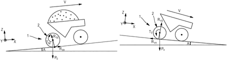
- FIG. 1A laden outbound uphill cycle of a dumper
- FIG. 1B unladen return downhill cycle of a dumper
- FIG. 2A partial view from above of a tread of a tire according to an embodiment of the invention
- FIG. 2B cross-sectional view of an element in relief of the first median portion
- FIG. 2C cross-sectional view of an element in relief of a second or third lateral portion
- FIG. 3A mechanical operation of an element in relief of the first median portion, under engine torque and in a laden state
- FIG. 3B mechanical operation of an element in relief of a second or third lateral portion, under engine torque and in a laden state
- FIG. 4A mechanical operation of an element in relief of the first median portion, under braking torque and in an unladen state
- FIG. 4B mechanical operation of an element in relief of a second or third lateral portion, under braking torque and in an unladen state
- FIG. 5A canonical curves of wear as a function of the resultant overall force for a tire of the prior art E and for a tire according to the invention I, in a laden state
- FIG. 5B canonical curves of wear as a function of the resultant overall force for a tire of the prior art E and for a tire according to the invention I, in an unladen state.
- FIG. 1A shows a laden outbound uphill cycle of a dumper.
- the laden dumper is climbing a gradient of angle A.
- Each tire 1 mounted on a driven axle, is subjected to an engine torque T M and to a load P C .
- the reactions of the ground on the tread 2 of the tire are a circumferential driving force R CX , oriented in the direction of movement V of the dumper, and a radial force R CZ , respectively.
- FIG. 1B shows an unladen return downhill cycle of a dumper.
- the unladen dumper is descending a gradient of angle A.
- Each tire 1 mounted on a driven axle, is subjected to a braking torque T F and to a load P V .
- the reactions of the ground on the tread 2 of the tire are a circumferential braking force R VX , oriented in the opposite direction to the movement V of the dumper, and a radial force R VZ , respectively.
- FIG. 2A is partial view from above of a tread 2 of a tire according to the invention.
- the tread 2 has a total width W T and comprises a first median portion 21 , axially delimited by a second and a third lateral portion 22 , 23 , respectively.
- the first median portion 21 has a median width W c at least equal to 20% and at most equal to 50% of the total width W T , and comprises elements in relief 31 that are separated from one another by cuts 41 , each element in relief 31 comprising a leading face 51 , which is intended to come into contact with the ground first, and a trailing face 61 , which is intended to come into contact with the ground last.
- Each of the second and third lateral portions ( 22 , 23 ) has a respective lateral width (W S2 , W S3 ) at least equal to 25% and at most equal to 40% of the total width W T , and respectively comprises elements in relief ( 32 , 33 ) that are separated from one another by cuts ( 42 , 43 ), each element in relief ( 32 , 33 ) comprising a leading face ( 52 , 53 ) and a trailing face ( 62 , 63 ).
- FIG. 2B is a cross-sectional view of an element in relief 31 of the first median portion, which is separated from the adjacent elements in relief by a cut 41 .
- Each element in relief 31 comprises a leading face 51 , which is intended to come into contact with the ground first and forms an angle A 51 with a radial plane YZ, and a trailing face 61 , which is intended to come into contact with the ground last and forms an angle A 61 with a radial plane YZ.
- the angles A 51 and A 61 are usually known as relief angles.
- the angle A 51 of the leading face 51 is an angle oriented positively in the anticlockwise direction.
- the angle A 61 of the trailing face 61 is an angle oriented positively in the clockwise direction. According to the invention, the angle A 51 of the leading face 51 of every element in relief 31 of the first median portion 21 is strictly less than the angle A 61 of the trailing face 61 of said element in relief 31 .
- FIG. 2C is a cross-sectional view of an element in relief ( 32 , 33 ) of a second or third lateral portion, which is separated from the adjacent elements in relief by a cut ( 42 , 43 ).
- Each element in relief ( 32 , 33 ) comprises a leading face ( 52 , 53 ), which is intended to come into contact with the ground first and forms an angle (A 52 , A 53 ) with a radial plane YZ, and a trailing face ( 62 , 63 ), which is intended to come into contact with the ground last and forms an angle (A 62 , A 63 ) with a radial plane YZ.
- angles (A 52 , A 53 ) and (A 62 , A 63 ) are usually known as relief angles.
- a local frame of reference XZ defined by a circumferential axis X, tangent to the circumference of the tire and oriented in the direction of rotation of the tire, and by a radial axis Z, perpendicular to the circumference of the tire and oriented towards the axis of rotation of the tire, the angle (A 52 , A 53 ) of the leading face ( 52 , 53 ) is an angle oriented positively in the anticlockwise direction.
- the angle (A 62 , A 63 ) of the trailing face ( 62 , 63 ) is an angle oriented positively in the clockwise direction.
- the angle (A 52 , A 53 ) of the leading face ( 52 , 53 ) of every element in relief ( 32 , 33 ) of each of the second and third lateral portions ( 22 , 23 ) is strictly greater than the angle (A 62 , A 63 ) of the trailing face ( 62 , 63 ) of said element in relief ( 32 , 33 ).
- FIG. 3A schematically shows the mechanical operation of an element in relief 31 of the first median portion, under engine torque T M and in a laden state, the tire having a direction of rotation R.
- FIG. 3B schematically shows the mechanical operation of an element in relief 32 of a second (or third) lateral portion, under engine torque T M and in a laden state, the tire having a direction of rotation R.
- FIG. 4A schematically shows the mechanical operation of an element in relief 31 of the first median portion, under braking torque T F and in an unladen state, the tire having a direction of rotation R.
- FIG. 4B schematically shows the mechanical operation of an element in relief 32 of a second (or third) lateral portion, under braking torque T F and in an unladen state, the tire having a direction of rotation R.
- FIG. 5A shows typical canonical curves of wear as a function of the resultant overall force for a tire of the prior art E and for a tire according to the invention I, respectively, in a laden state.
- the wear indicator U is a loss of mass (for example, expressed in g/km) or a loss of tread pattern height (for example, expressed in mm/km).
- the resultant overall force R G (for example, expressed in daN) applied to the tread by the ground is shown.
- the addition of an overall driving coupling force C GM makes it possible offset a value C GM of the canonical curve of wear in the direction of the increasing resultant overall forces R G .
- the wear indicator U decreases from the value U E for a tire of the prior art to the value U 1 for a tire according to the invention, hence a reduction in wear DU.
- FIG. 5B shows typical canonical curves of wear as a function of the resultant overall force for a tire of the prior art E and for a tire according to the invention I, respectively, in an unladen state.
- an overall braking coupling force C GF makes it possible offset a value C GF of the canonical curve of wear in the direction of the decreasing resultant overall forces R G .
- the wear indicator U decreases from the value U E for a tire of the prior art to the value U 1 for a tire according to the invention, hence a reduction in wear DU.
- the invention has been studied more particularly in the case of a tire of size 40.00R57, fitted to a rigid dumper with a total load capacity of 320 tonnes, and in the case of a tire of size 24.00R35, fitted to a rigid dumper with a total load capacity of 100 tonnes.
- Table 1 presents an example of the distribution of loads and coupling forces, between the first median portion and the second and third lateral portions of a tread of a tire according to the invention, the tire being mounted on a rear axle of a mining dumper carrying out an alternation of laden uphill outbound cycles and unladen downhill return cycles.
- the forces Z are the loads applied per portion of tread and generally to the entire tread, and the forces C are the corresponding coupling forces, generated by the Poisson effect.
- the first median portion bears 40% of the total load Z C and the second and third lateral portions bear 60% of the total load Z C , since the tread is in full contact with the ground across its entire width.
- the overall coupling force equal to +X times 20% of the total load Z C , is added to the overall driving slip force.
- the first median portion bears 80% of the total load Z V and the second and third lateral portions bear only 20% of the total load Z V , since the tread is in partial contact with the ground in the second and third lateral portions.
- the overall coupling force equal to ⁇ X times 60% of the total load Z V , is added to the overall braking slip force.
- the coupling levels are presumed to be identical between the first median portion and the second and third lateral portions. More generally, these respective median and lateral coupling levels can be different.
Landscapes
- Engineering & Computer Science (AREA)
- Mechanical Engineering (AREA)
- Tires In General (AREA)
Abstract
Description
| TABLE 1 | ||||
| First | Second | Third | ||
| median | lateral | lateral | Overall | |
| portion | portion | portion | tread | |
| Load applied | 0.4 * ZC | 0.3 * ZC | 0.3 * ZC | ZC |
| Z, in laden | ||||
| state under | ||||
| engine torque | ||||
| Coupling force | −X * 0.4 * ZC | +X * 0.3 * ZC | +X * 0.3 * ZC | +X * 0.2 * ZC |
| C, in laden | ||||
| state under | ||||
| engine torque | ||||
| Load applied | 0.8 * ZV | 0.1 * ZV | 0.1 * ZV | ZV |
| Z, in unladen | ||||
| state under | ||||
| braking torque | ||||
| Coupling force | −X * 0.8 * ZV | +X * 0.1 * ZV | +X * 0.1 * ZV | −X * 0.6 * ZV |
| C, in unladen | ||||
| state under | ||||
| braking torque | ||||
Claims (24)
Applications Claiming Priority (3)
| Application Number | Priority Date | Filing Date | Title |
|---|---|---|---|
| FR16/53106 | 2016-04-08 | ||
| FR1653106A FR3049900A1 (en) | 2016-04-08 | 2016-04-08 | DIFFERENTIATED DIRECTIONAL BEARING TAPE FOR A TIRE FOR A HEAVY VEHICLE |
| PCT/FR2017/050782 WO2017174916A1 (en) | 2016-04-08 | 2017-04-04 | Heavy-duty vehicle tyre |
Publications (2)
| Publication Number | Publication Date |
|---|---|
| US20190105949A1 US20190105949A1 (en) | 2019-04-11 |
| US11267292B2 true US11267292B2 (en) | 2022-03-08 |
Family
ID=56411726
Family Applications (1)
| Application Number | Title | Priority Date | Filing Date |
|---|---|---|---|
| US16/091,890 Active 2038-03-25 US11267292B2 (en) | 2016-04-08 | 2017-04-04 | Heavy-duty vehicle tire |
Country Status (3)
| Country | Link |
|---|---|
| US (1) | US11267292B2 (en) |
| FR (1) | FR3049900A1 (en) |
| WO (1) | WO2017174916A1 (en) |
Families Citing this family (1)
| Publication number | Priority date | Publication date | Assignee | Title |
|---|---|---|---|---|
| JP6954867B2 (en) * | 2018-06-19 | 2021-10-27 | 株式会社ブリヂストン | Heavy load tires |
Citations (9)
| Publication number | Priority date | Publication date | Assignee | Title |
|---|---|---|---|---|
| NZ213344A (en) | 1984-09-03 | 1987-06-30 | Sumitomo Rubber Ind | Tyre tread with radially outwardly diverging transverse grooves: groove walls inclined at different angles to suppress noise |
| NZ213345A (en) * | 1984-09-03 | 1988-01-08 | Sumitomo Rubber Ind | Tyre tread transverse groove walls of varying inclination to give increasing groove entrance orientation with wear |
| JPH0648122A (en) | 1992-07-30 | 1994-02-22 | Yokohama Rubber Co Ltd:The | Pneumatic radial tire for heavy load |
| US20010047840A1 (en) * | 1997-03-14 | 2001-12-06 | Pirelli Coordinamento Pneumatici S.P.A. | Low-running-temperature tyre |
| US6527024B1 (en) * | 1999-02-05 | 2003-03-04 | Sumitomo Rubber Industries Limited | Tire having tread including shoulder grooves |
| USD492246S1 (en) * | 2003-01-16 | 2004-06-29 | Michelin Recherche Et Technique S.A. | Tread of a tire |
| WO2004085175A1 (en) | 2003-03-25 | 2004-10-07 | Societe De Technologie Michelin | Method of mounting tyres to civil engineering vehicles and associated tyre |
| US20120132331A1 (en) * | 2010-11-30 | 2012-05-31 | The Goodyear Tire & Rubber Cmpany | Pneumatic tire |
| US20150336429A1 (en) * | 2012-12-19 | 2015-11-26 | Bridgestone Americas Tire Operations, Llc | Tire with bi-directional performance |
-
2016
- 2016-04-08 FR FR1653106A patent/FR3049900A1/en not_active Withdrawn
-
2017
- 2017-04-04 US US16/091,890 patent/US11267292B2/en active Active
- 2017-04-04 WO PCT/FR2017/050782 patent/WO2017174916A1/en not_active Ceased
Patent Citations (10)
| Publication number | Priority date | Publication date | Assignee | Title |
|---|---|---|---|---|
| NZ213344A (en) | 1984-09-03 | 1987-06-30 | Sumitomo Rubber Ind | Tyre tread with radially outwardly diverging transverse grooves: groove walls inclined at different angles to suppress noise |
| NZ213345A (en) * | 1984-09-03 | 1988-01-08 | Sumitomo Rubber Ind | Tyre tread transverse groove walls of varying inclination to give increasing groove entrance orientation with wear |
| JPH0648122A (en) | 1992-07-30 | 1994-02-22 | Yokohama Rubber Co Ltd:The | Pneumatic radial tire for heavy load |
| US20010047840A1 (en) * | 1997-03-14 | 2001-12-06 | Pirelli Coordinamento Pneumatici S.P.A. | Low-running-temperature tyre |
| US6527024B1 (en) * | 1999-02-05 | 2003-03-04 | Sumitomo Rubber Industries Limited | Tire having tread including shoulder grooves |
| USD492246S1 (en) * | 2003-01-16 | 2004-06-29 | Michelin Recherche Et Technique S.A. | Tread of a tire |
| WO2004085175A1 (en) | 2003-03-25 | 2004-10-07 | Societe De Technologie Michelin | Method of mounting tyres to civil engineering vehicles and associated tyre |
| US20060037684A1 (en) | 2003-03-25 | 2006-02-23 | Michelin Recherche Et Technique S.A. | Method of mounting tires to civil engineering vehicles and associated tire |
| US20120132331A1 (en) * | 2010-11-30 | 2012-05-31 | The Goodyear Tire & Rubber Cmpany | Pneumatic tire |
| US20150336429A1 (en) * | 2012-12-19 | 2015-11-26 | Bridgestone Americas Tire Operations, Llc | Tire with bi-directional performance |
Also Published As
| Publication number | Publication date |
|---|---|
| WO2017174916A1 (en) | 2017-10-12 |
| US20190105949A1 (en) | 2019-04-11 |
| FR3049900A1 (en) | 2017-10-13 |
Similar Documents
| Publication | Publication Date | Title |
|---|---|---|
| CN100475567C (en) | Method of mounting tires to civil engineering vehicles and associated tire | |
| JP2617713B2 (en) | Pneumatic radial tire for heavy loads | |
| US20230373253A1 (en) | Tire with Improved Grip for a Heavy Civil Engineering Vehicle | |
| US10780745B2 (en) | Incised tread for civil engineering tire | |
| JPH05319029A (en) | Pneumatic radial tire for heavy load | |
| US7066226B1 (en) | Fuel efficient vehicle tire having a variable footprint and low rolling resistance | |
| US12384204B2 (en) | Tire tread for a heavy-duty vehicle of construction plant type | |
| US20180370287A1 (en) | Tire Tread For A Heavy Civil Engineering Vehicle | |
| US11192403B2 (en) | Siped tread for off-road tire | |
| US11267292B2 (en) | Heavy-duty vehicle tire | |
| US11465449B2 (en) | Heavy-duty goods vehicle tire | |
| JP2001121927A (en) | Pneumatic tire | |
| AU2021403909A1 (en) | Tyre tread for a heavy vehicle with improved robustness | |
| JP2003039917A (en) | Pneumatic radial tire for heavy loads | |
| US11697310B2 (en) | Tire comprising a tread containing reinforcing elements | |
| CN109982870B (en) | Tread for civil engineering machinery tires including improved ventilation cavities | |
| JPH0834205A (en) | Pneumatic tire | |
| JP2752685B2 (en) | Pneumatic tires for heavy loads that prevent uneven wear | |
| CN110461624B (en) | A tire with a tread with grooves and reinforcing elements with undercut sides | |
| JP4149057B2 (en) | Pneumatic tire | |
| JP2000158913A (en) | Pneumatic tire | |
| CN112166043B (en) | Tyre tread for heavy civil engineering vehicle comprising a ventilation cut | |
| US7448457B2 (en) | Heavy vehicle | |
| US7987932B2 (en) | Heavy vehicle | |
| CN1822978A (en) | Heavy vehicle |
Legal Events
| Date | Code | Title | Description |
|---|---|---|---|
| FEPP | Fee payment procedure |
Free format text: ENTITY STATUS SET TO UNDISCOUNTED (ORIGINAL EVENT CODE: BIG.); ENTITY STATUS OF PATENT OWNER: LARGE ENTITY |
|
| AS | Assignment |
Owner name: COMPAGNIE GENERALE DES ETABLISSEMENTS MICHELIN, FRANCE Free format text: ASSIGNMENT OF ASSIGNORS INTEREST;ASSIGNOR:MANSUY, PHILIPPE;REEL/FRAME:047744/0917 Effective date: 20181113 Owner name: COMPAGNIE GENERALE DES ETABLISSEMENTS MICHELIN, FR Free format text: ASSIGNMENT OF ASSIGNORS INTEREST;ASSIGNOR:MANSUY, PHILIPPE;REEL/FRAME:047744/0917 Effective date: 20181113 |
|
| STPP | Information on status: patent application and granting procedure in general |
Free format text: NON FINAL ACTION MAILED |
|
| STPP | Information on status: patent application and granting procedure in general |
Free format text: FINAL REJECTION MAILED |
|
| STPP | Information on status: patent application and granting procedure in general |
Free format text: RESPONSE AFTER FINAL ACTION FORWARDED TO EXAMINER |
|
| STPP | Information on status: patent application and granting procedure in general |
Free format text: ADVISORY ACTION MAILED |
|
| STPP | Information on status: patent application and granting procedure in general |
Free format text: DOCKETED NEW CASE - READY FOR EXAMINATION |
|
| STPP | Information on status: patent application and granting procedure in general |
Free format text: NOTICE OF ALLOWANCE MAILED -- APPLICATION RECEIVED IN OFFICE OF PUBLICATIONS |
|
| STPP | Information on status: patent application and granting procedure in general |
Free format text: PUBLICATIONS -- ISSUE FEE PAYMENT VERIFIED |
|
| STCF | Information on status: patent grant |
Free format text: PATENTED CASE |
|
| MAFP | Maintenance fee payment |
Free format text: PAYMENT OF MAINTENANCE FEE, 4TH YEAR, LARGE ENTITY (ORIGINAL EVENT CODE: M1551); ENTITY STATUS OF PATENT OWNER: LARGE ENTITY Year of fee payment: 4 |