US11267026B2 - Sheet metal rolling machine for forming complex shapes - Google Patents
Sheet metal rolling machine for forming complex shapes Download PDFInfo
- Publication number
- US11267026B2 US11267026B2 US16/442,914 US201916442914A US11267026B2 US 11267026 B2 US11267026 B2 US 11267026B2 US 201916442914 A US201916442914 A US 201916442914A US 11267026 B2 US11267026 B2 US 11267026B2
- Authority
- US
- United States
- Prior art keywords
- roller
- shaping roller
- shaping
- axis
- drive
- Prior art date
- Legal status (The legal status is an assumption and is not a legal conclusion. Google has not performed a legal analysis and makes no representation as to the accuracy of the status listed.)
- Active, expires
Links
Images


Classifications
-
- B—PERFORMING OPERATIONS; TRANSPORTING
- B21—MECHANICAL METAL-WORKING WITHOUT ESSENTIALLY REMOVING MATERIAL; PUNCHING METAL
- B21B—ROLLING OF METAL
- B21B13/00—Metal-rolling stands, i.e. an assembly composed of a stand frame, rolls, and accessories
- B21B13/02—Metal-rolling stands, i.e. an assembly composed of a stand frame, rolls, and accessories with axes of rolls arranged horizontally
-
- B—PERFORMING OPERATIONS; TRANSPORTING
- B21—MECHANICAL METAL-WORKING WITHOUT ESSENTIALLY REMOVING MATERIAL; PUNCHING METAL
- B21D—WORKING OR PROCESSING OF SHEET METAL OR METAL TUBES, RODS OR PROFILES WITHOUT ESSENTIALLY REMOVING MATERIAL; PUNCHING METAL
- B21D5/00—Bending sheet metal along straight lines, e.g. to form simple curves
- B21D5/14—Bending sheet metal along straight lines, e.g. to form simple curves by passing between rollers
-
- B—PERFORMING OPERATIONS; TRANSPORTING
- B21—MECHANICAL METAL-WORKING WITHOUT ESSENTIALLY REMOVING MATERIAL; PUNCHING METAL
- B21B—ROLLING OF METAL
- B21B1/00—Metal-rolling methods or mills for making semi-finished products of solid or profiled cross-section; Sequence of operations in milling trains; Layout of rolling-mill plant, e.g. grouping of stands; Succession of passes or of sectional pass alternations
- B21B1/22—Metal-rolling methods or mills for making semi-finished products of solid or profiled cross-section; Sequence of operations in milling trains; Layout of rolling-mill plant, e.g. grouping of stands; Succession of passes or of sectional pass alternations for rolling plates, strips, bands or sheets of indefinite length
-
- B—PERFORMING OPERATIONS; TRANSPORTING
- B21—MECHANICAL METAL-WORKING WITHOUT ESSENTIALLY REMOVING MATERIAL; PUNCHING METAL
- B21B—ROLLING OF METAL
- B21B35/00—Drives for metal-rolling mills, e.g. hydraulic drives
- B21B35/14—Couplings, driving spindles, or spindle carriers specially adapted for, or specially arranged in, metal-rolling mills
Definitions
- This disclosure relates to a machine and process for forming three dimensional shapes from sheet metal.
- Machines for shaping sheet metal using three or four rolls are known.
- One or two driven rolls move the workpiece until on passing through one or two adjustable bending rolls it has assumed the desired shape.
- these machines have a pair of drive rolls (often referred to as pinch rolls) and one shaping roll in the back if it is a three-roll machine.
- Four-roll machines have a shaping roller in the front if the drive rolls and a shaping roll after the drive rolls. The drive rollers feed the sheet metal through the shaping roller, which is generally adjustable in limited manners to provide the desired shapes.
- a forming machine for forming complex shapes can comprise a first drive roller and a second drive roller to feed a material through the machine for shaping.
- First drive roller and second drive roller can be coplanar on an x-z plane, fixed on the x-axis, and adjustable about the z-axis to increase or decrease the distance between the same to accommodate varying thicknesses in material.
- a first shaping roller and a second shaping roller that are also coplanar on the x-z plane and fixed on the x-axis are provided with ends tiltable on the z-axis with respect to each other. While the first drive roller and the second drive roller remain parallel with respect to each other, the first shaping roller and the second shaping roller are not constrained in a parallel orientation, but rather can tilt with respect to each other.
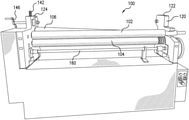
- FIG. 1 is a front perspective view of a sheet metal forming machine according to this disclosure.
- FIG. 2 is a right-side view of the machine of FIG. 1 .
- FIG. 3 is a left-side view of the machine of FIG. 1 .
- FIG. 4 shows the rollers in the forming machine of FIG. 1 separated from the rest of the forming machine.
- FIG. 5 is an illustration of the adjustable nature of the axes of the rollers of FIG. 4 .
- FIG. 6 is an illustration of forming material from the perspective A-A of the right side of the forming machine.
- FIG. 7 is an illustration of forming the same material from the perspective B-B of the left side of the forming machine.
- Forming machine 100 comprises generally of a first drive roller 102 , a second drive roller 104 , a first shaping roller 106 and a second shaping roller 108 .
- First drive roller 102 and second drive roller 104 are positioned co-planar and parallel with respect to each other about an x-z plane with an adjustable spacing with respect to each other on a z-axis to accommodate material of varying thicknesses.
- First shaping roller 106 and second shaping roller 108 are similarly co-planar about the x-z plane but with each end independently adjustable about the z-axis. This novel arrangement of first shaping roller 106 and second shaping roller 108 allows for the forming of complex geometrical shapes or waves in the material.
- first drive roller 102 and second drive roller 104 are independently driven in opposite directions of rotation to feed a material 200 through forming machine 100 for shaping.
- First drive roller 102 and second drive roller 104 are coplanar on the x-z plane and fixed on the x-axis parallel to each other.
- One or both of the first drive roller 102 and second drive roller 104 can be adjusted about the z-axis to increase or decrease the distance between the same to accommodate varying thicknesses in material 200 .
- First shaping roller 106 is tiltable with one end higher than the other end and second shaping roller 108 is tiltable with one end higher than the other end. This means that each end of both the first shaping roller 106 and second shaping roller 108 is adjustable about the z-axis to raise and lower the respective ends with respect to each other. Unlike first drive roller 102 and second drive roller 104 , first shaping roller 106 and second shaping roller 108 are not constrained parallel with respect to each other. Both first shaping roller 106 and second shaping roller 108 are also coplanar on the x-z plane and fixed on the x-axis.
- Forming machine 100 further comprises of a frame 120 for holding first drive roller 102 , second drive roller 104 , first shaping roller 106 and second shaping roller 108 in position.
- Frame 120 can comprise a right side member 122 and a left side member 124 .
- FIG. 2 is a right-side view of forming machine 100 that shows right side member 122 .
- Right side member 122 comprises of a machined out area for receiving the bearings that hold the rollers.
- a pillow block bearing 126 is positioned in the machined out area to locate on the x-axis the right side end of first shaping roller 106 .
- Another pillow block bearing 128 is positioned in the machined out area below pillow block bearing 126 to locate on the x-axis the right side end of second shaping roller 108 .
- Pillow block bearing 126 is attached to an elevation system 129 to raise and lower pillow block bearing 126 about the z-axis.
- Elevation system 129 can comprise a threaded shaft 130 attached at one end to pillow block bearing 126 and at the other end fed through a slave gear 132 .
- Slave gear 132 is circumscribed by teeth so that it can be rotate by a drive gear attached to a handle 134 . Rotation of handle 134 rotates the drive gear which rotates slave gear 132 to cause threaded shaft 130 to be drawn up or down based on the direction of rotation.
- Elevation system 134 can comprise a threaded shaft 133 attached at one end to pillow block bearing 128 and at the other end fed through a slave gear that is connected to a drive gear in the manner described above.
- a handle 134 is combined to the drive gear to rotate the drive gear in the manner described above to raise and lower pillow block bearing 128 .
- FIG. 3 shows the left side of forming machine 100 .
- left side member 124 comprising a machined out area for receiving a pillow block bearing 136 is positioned in the machined out area to locate on the x-axis the left side end of first shaping roller 106 .
- Another pillow block bearing 138 is positioned in the machined out area below pillow block bearing 136 to locate on the x-axis the left side end of second shaping roller 108 .
- Pillow block bearing 136 is attached to an elevation system 140 to raise and lower pillow block bearing 136 about the z-axis.
- Elevation system 140 can comprise a threaded shaft 142 attached at one end to pillow block bearing 136 and at the other end fed through a slave gear 144 .
- Slave gear 144 is circumscribed by teeth so that it can be rotate by a drive gear attached to a handle 146 .
- Rotation of handle 146 rotates the drive gear which rotates slave gear 144 to cause threaded shaft 142 to be drawn up or down based on the direction of rotation.
- Elevation system 140 can comprise a threaded shaft attached at one end to pillow block bearing 138 and at the other end fed through a slave gear that is connected to a drive gear in the manner described above.
- a handle 150 is combined to the drive gear to rotate the drive gear in the manner described above to raise and lower pillow block bearing 138 .
- first drive roller 102 and second drive roller 104 can be moved upward and downward on the z-axis in a manner similar to the above-described first shaping roller 106 and second shaping roller 108 .
- second drive roller 104 is combined to an elevation system 152 .
- the right-side end of second drive roller 104 is connected to a pillow block bearing 154 .
- a threaded shaft 156 is attached at one end to pillow block bearing 154 and at the other end fed through a slave gear with circumscribed teeth coupled to a drive gear that is attached to a handle 158 .
- Handle 158 is also combined to a cross rod 160 (shown in FIG.
- rotation of handle 158 rotates the drive gear which rotates slave gear to cause threaded shaft 156 to be drawn up or down based on the direction of rotation with similar action occurring simultaneously on the other side via rotation of cross rod 160 .
- FIG. 3 shows a motor 162 coupled to a drive system 164 to drive first drive roller 102 one direction and second drive roller 104 in the counter rotational direction.
- Drive system 164 comprises of a first gear 166 coupled to the shaft of motor 162 .
- a chain 168 couples first gear 166 to a second gear 170 .
- a third gear 171 couples second gear 170 to a fourth gear 175 that is combined to first drive roller 102 .
- Fourth gear 175 is coupled to a fifth gear 177 , which is combined to second drive roller 104 .
- This configuration drives first drive roller 102 one direction and second drive roller 104 in the counter rotational direction.
- Forming machine 100 can be used to form complex three dimensional shapes.
- One end of either one or both of first shaping roller 106 and second shaping roller 108 can be raised and the other end is lowered. This effectively applies an upward bending force on one edge of the sheet and a downward bending force on the other edge of the sheet and no bending force in the middle of the sheet.
- First shaping roller 106 and second shaping roller 108 can also be raised and lowered at unequal rates so the upward and downward bending forces are not equal in opposite directions to move the unformed portion of the sheet off center. This arrangement applies varying bending forces along the width of the sheet as it goes through first shaping roller 106 and second shaping roller 108 .
- FIG. 4 shows first drive roller 102 , second drive roller 104 , first shaping roller 106 , and second shaping roller 108 separated from the rest of forming machine 100 to better illustrate their maneuverability.
- Each of the rollers rotates about a corresponding axis.
- First drive roller 102 rotates about axis 172
- second drive roller 104 rotates about axis 174
- first shaping roller 106 rotates about axis 176
- second shaping roller 108 rotates about axis 178 .
- axis 172 and axis 174 are positioned co-planar and parallel with respect to each other about an x-z plane with an adjustable spacing with respect to each other on a z-axis to accommodate material of varying thicknesses.
- Axis 176 and axis 178 are similarly co-planar about the x-z plane but with each end independently adjustable about the z-axis.
- This novel arrangement of first shaping roller 106 and second shaping roller 108 allows for the forming of complex geometrical shapes or waves in the material.
- FIG. 5 is an illustration of the adjustable nature of the axes of the rollers of FIG. 4 . This illustration shows that axis 176 and axis 178 can each be tilted on each end with respect to axis 172 and axis 174 that remain parallel with respect to the ground plane.
- FIGS. 6 and 7 are illustrations taken from the perspective of A-A and B-B in FIG. 4 , respectively to show how material 200 can be formed with complex waves. As seen in these figures, as the right side of material 200 is bent upward with respect to the ground plane, material 200 can be bent downward with respect to the ground plane. This forms material 200 with a complex undulating wave across material 200 .
Landscapes
- Engineering & Computer Science (AREA)
- Mechanical Engineering (AREA)
- Bending Of Plates, Rods, And Pipes (AREA)
Abstract
Description
Claims (18)
Priority Applications (1)
| Application Number | Priority Date | Filing Date | Title |
|---|---|---|---|
| US16/442,914 US11267026B2 (en) | 2019-06-17 | 2019-06-17 | Sheet metal rolling machine for forming complex shapes |
Applications Claiming Priority (1)
| Application Number | Priority Date | Filing Date | Title |
|---|---|---|---|
| US16/442,914 US11267026B2 (en) | 2019-06-17 | 2019-06-17 | Sheet metal rolling machine for forming complex shapes |
Publications (2)
| Publication Number | Publication Date |
|---|---|
| US20200391262A1 US20200391262A1 (en) | 2020-12-17 |
| US11267026B2 true US11267026B2 (en) | 2022-03-08 |
Family
ID=73746011
Family Applications (1)
| Application Number | Title | Priority Date | Filing Date |
|---|---|---|---|
| US16/442,914 Active 2040-01-22 US11267026B2 (en) | 2019-06-17 | 2019-06-17 | Sheet metal rolling machine for forming complex shapes |
Country Status (1)
| Country | Link |
|---|---|
| US (1) | US11267026B2 (en) |
Citations (9)
| Publication number | Priority date | Publication date | Assignee | Title |
|---|---|---|---|---|
| US2843178A (en) | 1956-09-11 | 1958-07-15 | Sutton Eng Co | Apparatus for correcting the contour of extruded or rolled sections |
| US3081651A (en) * | 1960-04-28 | 1963-03-19 | United States Steel Corp | Method and apparatus for correcting gage of strip during rolling |
| US3557594A (en) | 1968-11-20 | 1971-01-26 | Allis Chalmers Mfg Co | Method of making a truncated conical body |
| US3623349A (en) | 1968-08-10 | 1971-11-30 | Christian Hausler | Bending machines |
| US4195509A (en) * | 1976-06-12 | 1980-04-01 | Hinrichs Gesellschaft Mit Beschrankter Haftung | Device for bending ring segment-shaped plate blanks into conically shaped parts |
| EP0204290A2 (en) | 1985-06-04 | 1986-12-10 | Chr. Haeusler AG | A sheetmetal rolling machine for making a conical shell from a sheetmetal blank |
| DE3940984A1 (en) | 1989-12-12 | 1991-06-13 | Walter E Spaeth | Forming of sheet metal shells or tubes - by using pair of bending rollers with mechanism to swing one roller about the axis |
| JPH05146802A (en) * | 1991-02-25 | 1993-06-15 | Nippon Steel Corp | Method for manufacturing steel sheet having plate thickness inclination in the width direction |
| US6655182B2 (en) * | 2001-05-18 | 2003-12-02 | Lindab Ab | Apparatus and method for reshaping tubes |
-
2019
- 2019-06-17 US US16/442,914 patent/US11267026B2/en active Active
Patent Citations (10)
| Publication number | Priority date | Publication date | Assignee | Title |
|---|---|---|---|---|
| US2843178A (en) | 1956-09-11 | 1958-07-15 | Sutton Eng Co | Apparatus for correcting the contour of extruded or rolled sections |
| US3081651A (en) * | 1960-04-28 | 1963-03-19 | United States Steel Corp | Method and apparatus for correcting gage of strip during rolling |
| US3623349A (en) | 1968-08-10 | 1971-11-30 | Christian Hausler | Bending machines |
| US3557594A (en) | 1968-11-20 | 1971-01-26 | Allis Chalmers Mfg Co | Method of making a truncated conical body |
| US4195509A (en) * | 1976-06-12 | 1980-04-01 | Hinrichs Gesellschaft Mit Beschrankter Haftung | Device for bending ring segment-shaped plate blanks into conically shaped parts |
| EP0204290A2 (en) | 1985-06-04 | 1986-12-10 | Chr. Haeusler AG | A sheetmetal rolling machine for making a conical shell from a sheetmetal blank |
| US4735076A (en) | 1985-06-04 | 1988-04-05 | Chr. Haeusler Ag | Process for the production of a conical shell using sheet metal bending rolls |
| DE3940984A1 (en) | 1989-12-12 | 1991-06-13 | Walter E Spaeth | Forming of sheet metal shells or tubes - by using pair of bending rollers with mechanism to swing one roller about the axis |
| JPH05146802A (en) * | 1991-02-25 | 1993-06-15 | Nippon Steel Corp | Method for manufacturing steel sheet having plate thickness inclination in the width direction |
| US6655182B2 (en) * | 2001-05-18 | 2003-12-02 | Lindab Ab | Apparatus and method for reshaping tubes |
Non-Patent Citations (1)
| Title |
|---|
| International Search Report and Written Opinion dated Oct. 3, 2019 for counterpart International Application No. PCT/US2019/037451. |
Also Published As
| Publication number | Publication date |
|---|---|
| US20200391262A1 (en) | 2020-12-17 |
Similar Documents
| Publication | Publication Date | Title |
|---|---|---|
| JP5033120B2 (en) | Production line and method for forming and processing profiles | |
| TW200911515A (en) | Folding device for a folding and gluing machine | |
| JP2008539083A5 (en) | ||
| EP0930112A3 (en) | Spring manufacturing machine | |
| US11267026B2 (en) | Sheet metal rolling machine for forming complex shapes | |
| CN214719532U (en) | Plate straightener convexity adjusting mechanism and plate straightener | |
| WO2020256686A1 (en) | Sheet metal rolling machine for forming complex shapes | |
| JP2008081258A (en) | Paper processing device | |
| CN211386416U (en) | Numerical control hydraulic three-roller symmetric plate bending machine | |
| JP2754308B2 (en) | Knife bending equipment | |
| EP0976468B1 (en) | Roller mount with three-axis freedom | |
| CN221086977U (en) | Hoop forming machine | |
| KR101907854B1 (en) | Metal Processing Device And Method of Manufacturing Ring Using The Same | |
| JPH09165890A (en) | Folding machine | |
| CN105642714B (en) | Prepare the rolling device of sheet metal gradient structure | |
| CN210995959U (en) | Fixing device for upper and lower roll shafts of four-roll bending machine | |
| CN208146748U (en) | Forming integrated machine is rushed in the rolling of banding sheet material | |
| JPS6020811A (en) | Milling machine | |
| JPH0698402B2 (en) | Welded steel pipe strip edge forming roll | |
| JPS62230424A (en) | Multi-roll type round bar straightening machine | |
| CN212469331U (en) | Cold rolling forming machine | |
| CN212682132U (en) | Multifunctional plate rolling machine | |
| CN206732549U (en) | A kind of coiled material production equipment | |
| CN218836753U (en) | Metal saw plate calendering trimming mechanism | |
| CN220637241U (en) | Large-size sapphire window sheet processing device |
Legal Events
| Date | Code | Title | Description |
|---|---|---|---|
| AS | Assignment |
Owner name: METAL DESIGN SYSTEMS, INC., IOWA Free format text: ASSIGNMENT OF ASSIGNORS INTEREST;ASSIGNOR:SAUERWEIN, DAVID A.;REEL/FRAME:049485/0984 Effective date: 20190613 |
|
| FEPP | Fee payment procedure |
Free format text: ENTITY STATUS SET TO UNDISCOUNTED (ORIGINAL EVENT CODE: BIG.); ENTITY STATUS OF PATENT OWNER: SMALL ENTITY |
|
| FEPP | Fee payment procedure |
Free format text: ENTITY STATUS SET TO SMALL (ORIGINAL EVENT CODE: SMAL); ENTITY STATUS OF PATENT OWNER: SMALL ENTITY |
|
| STPP | Information on status: patent application and granting procedure in general |
Free format text: NON FINAL ACTION MAILED |
|
| STPP | Information on status: patent application and granting procedure in general |
Free format text: RESPONSE TO NON-FINAL OFFICE ACTION ENTERED AND FORWARDED TO EXAMINER |
|
| STPP | Information on status: patent application and granting procedure in general |
Free format text: FINAL REJECTION MAILED |
|
| STPP | Information on status: patent application and granting procedure in general |
Free format text: RESPONSE AFTER FINAL ACTION FORWARDED TO EXAMINER |
|
| STPP | Information on status: patent application and granting procedure in general |
Free format text: ADVISORY ACTION MAILED |
|
| STPP | Information on status: patent application and granting procedure in general |
Free format text: DOCKETED NEW CASE - READY FOR EXAMINATION |
|
| STPP | Information on status: patent application and granting procedure in general |
Free format text: NOTICE OF ALLOWANCE MAILED -- APPLICATION RECEIVED IN OFFICE OF PUBLICATIONS |
|
| STCF | Information on status: patent grant |
Free format text: PATENTED CASE |
|
| MAFP | Maintenance fee payment |
Free format text: PAYMENT OF MAINTENANCE FEE, 4TH YR, SMALL ENTITY (ORIGINAL EVENT CODE: M2551); ENTITY STATUS OF PATENT OWNER: SMALL ENTITY Year of fee payment: 4 |