US11266321B2 - Vital sign processing device, vital sign processing method, and information processing device - Google Patents
Vital sign processing device, vital sign processing method, and information processing device Download PDFInfo
- Publication number
- US11266321B2 US11266321B2 US16/328,563 US201716328563A US11266321B2 US 11266321 B2 US11266321 B2 US 11266321B2 US 201716328563 A US201716328563 A US 201716328563A US 11266321 B2 US11266321 B2 US 11266321B2
- Authority
- US
- United States
- Prior art keywords
- pulse
- heart
- rate
- signal
- wave
- Prior art date
- Legal status (The legal status is an assumption and is not a legal conclusion. Google has not performed a legal analysis and makes no representation as to the accuracy of the status listed.)
- Active, expires
Links
Images


Classifications
-
- A—HUMAN NECESSITIES
- A61—MEDICAL OR VETERINARY SCIENCE; HYGIENE
- A61B—DIAGNOSIS; SURGERY; IDENTIFICATION
- A61B5/00—Measuring for diagnostic purposes; Identification of persons
- A61B5/02—Detecting, measuring or recording for evaluating the cardiovascular system, e.g. pulse, heart rate, blood pressure or blood flow
- A61B5/024—Measuring pulse rate or heart rate
- A61B5/02438—Measuring pulse rate or heart rate with portable devices, e.g. worn by the patient
-
- A—HUMAN NECESSITIES
- A61—MEDICAL OR VETERINARY SCIENCE; HYGIENE
- A61B—DIAGNOSIS; SURGERY; IDENTIFICATION
- A61B5/00—Measuring for diagnostic purposes; Identification of persons
- A61B5/68—Arrangements of detecting, measuring or recording means, e.g. sensors, in relation to patient
- A61B5/6801—Arrangements of detecting, measuring or recording means, e.g. sensors, in relation to patient specially adapted to be attached to or worn on the body surface
- A61B5/6802—Sensor mounted on worn items
- A61B5/681—Wristwatch-type devices
-
- A—HUMAN NECESSITIES
- A61—MEDICAL OR VETERINARY SCIENCE; HYGIENE
- A61B—DIAGNOSIS; SURGERY; IDENTIFICATION
- A61B5/00—Measuring for diagnostic purposes; Identification of persons
- A61B5/72—Signal processing specially adapted for physiological signals or for diagnostic purposes
- A61B5/7203—Signal processing specially adapted for physiological signals or for diagnostic purposes for noise prevention, reduction or removal
-
- A—HUMAN NECESSITIES
- A61—MEDICAL OR VETERINARY SCIENCE; HYGIENE
- A61B—DIAGNOSIS; SURGERY; IDENTIFICATION
- A61B5/00—Measuring for diagnostic purposes; Identification of persons
- A61B5/72—Signal processing specially adapted for physiological signals or for diagnostic purposes
- A61B5/7221—Determining signal validity, reliability or quality
-
- A—HUMAN NECESSITIES
- A61—MEDICAL OR VETERINARY SCIENCE; HYGIENE
- A61B—DIAGNOSIS; SURGERY; IDENTIFICATION
- A61B5/00—Measuring for diagnostic purposes; Identification of persons
- A61B5/72—Signal processing specially adapted for physiological signals or for diagnostic purposes
- A61B5/7225—Details of analogue processing, e.g. isolation amplifier, gain or sensitivity adjustment, filtering, baseline or drift compensation
-
- A—HUMAN NECESSITIES
- A61—MEDICAL OR VETERINARY SCIENCE; HYGIENE
- A61B—DIAGNOSIS; SURGERY; IDENTIFICATION
- A61B5/00—Measuring for diagnostic purposes; Identification of persons
- A61B5/72—Signal processing specially adapted for physiological signals or for diagnostic purposes
- A61B5/7235—Details of waveform analysis
- A61B5/725—Details of waveform analysis using specific filters therefor, e.g. Kalman or adaptive filters
Definitions
- the present technology relates to a vital sign processing device that outputs heart-rate information items of a user, a vital sign processing method, and an information processing device.
- PPG photoplethysmography
- Patent Literature 1 describes a pulsimeter including a pulse-wave sensor and a body-motion sensor.
- an adaptive filter that uses, as a monitoring signal, a pulse-wave signal to be output from the pulse-wave sensor, and receives, as an input signal, a body-motion signal to be output from the body-motion sensor.
- a predictive value of a body-motion component to be calculated by the adaptive filter is subtracted from the pulse-wave signal, and a Fast Fourier Transform (FFT) process is executed on a resultant residual signal.
- FFT Fast Fourier Transform
- a component at a highest level is extracted as a pulse-wave component from resultant frequency components. With this, a pulse rate per minute is calculated. In this way, the pulse rate is accurately measured (refer, for example, to paragraphs [0007] to [0012] of the specification and FIG. 1 of Patent Literature 1).
- the present technology has been made to provide a vital sign processing device, a vital sign processing method, and an information processing device that enable highly accurate heart-rate measurement.
- a vital sign processing device including a pulse-wave sensor unit, an output unit, and a first filter unit.
- the pulse-wave sensor unit outputs a pulse-wave signal.
- the output unit outputs a heart-rate information item on the basis of the output pulse-wave signal.
- the first filter unit filters the pulse-wave signal on the basis of the heart-rate information item.
- a highly accurate heart-rate information item is output on the basis of the filtered pulse-wave signal. In this way, highly accurate heart-rate measurement can be performed.
- the first filter unit may set the first frequency band on the basis of a heart rate included in the heart-rate information item.
- the first frequency band is set on the basis of a previous heart rate, and hence the heart-rate information item can be output with high accuracy.
- the filter bank may include a plurality of band-pass filters
- the filter may select, on the basis of the heart rate and from the first filter bank, a filter that allows the first frequency band to pass through the filter.
- the filter bank By using the filter bank in this way, the pulse-wave signal can be easily filtered.
- the vital sign processing device may further include
- a plurality of calculation units each of which calculates a heart-rate-candidate information item and a reliability of the heart-rate-candidate information item on the basis of the output pulse-wave signal.
- the output unit may output the heart-rate information item on the basis of the heart-rate-candidate information item and the reliability of the heart-rate-candidate information item, the heart-rate-candidate information item and the reliability being calculated by each of the plurality of calculation units.
- Each of the plurality of calculation units may calculate the heart-rate-candidate information item and the reliability of the heart-rate-candidate information item on the basis of the pulse-wave signal filtered by the first filter unit.
- the heart-rate-candidate information item for example, can be calculated with high accuracy.
- the vital sign processing device may further include:
- a body-motion sensor that outputs a body-motion signal
- each of the plurality of calculation units may calculate the heart-rate-candidate information item and the reliability of the heart-rate-candidate information item on the basis of the pulse-wave signal from which the body-motion noise has been separated.
- the heart-rate-candidate information item can be calculated with high accuracy.
- the first filter unit may filter the pulse-wave signal from which the body-motion noise has been separated by the noise-reduction processing unit.
- the first frequency band of the pulse-wave signal from which the body-motion noise has been separated is allowed to pass, and other bands can be removed. In this way, highly accurate heart-rate measurement can be performed.
- the controller may include a plurality of pulse-wave sensors, and
- the vital sign processing device may further include
- a generating unit that generates, on the basis of the plurality of pulse-wave-candidate signals that are generated by the plurality of pulse-wave sensors, a reference signal for separating the body-motion noise.
- the filter may include an adaptive filter to which the reference signal is input as an input signal, and
- the vital sign processing device may further include
- the reference signal can be generated with high accuracy.
- the body-motion noise can be reduced with high accuracy.
- the second filter unit may set the second frequency band on the basis of a heart rate included in the heart-rate information item.
- the second frequency band is set on the basis of the previous heart rate, and hence the reference signal can be generated with high accuracy.
- the second filter bank including a plurality of band-elimination filters
- a filter may select, on the basis of the heart rate and from the second filter bank, a filter that removes the second frequency band.
- the filter bank By using the filter bank in this way, the reference signal can be easily filtered.
- the second filter unit may filter at least one of the plurality of pulse-wave-candidate signals or the body-motion signal.
- the generating unit may generate the reference signal on the basis of an output from the second filter unit.
- the reference signal can be calculated with high accuracy.
- the generating unit may generate the reference signal on the basis of the plurality of pulse-wave-candidate signals filtered by the first filter unit.
- the noise-reduction processing unit may output an error signal obtained by subtraction of the output value of the adaptive filter from the pulse-wave signal filtered by the first filter unit.
- Processes such as the separation of the body-motion noise are executed intensively on a frequency band of the heart rate.
- the error signal for example, can be calculated with high accuracy.
- the filter may then output the filtered reference signal to the adaptive filter.
- the processes such as the separation of the body-motion noise are executed on the basis of the reference signal from which the second frequency band has been removed.
- the error signal for example, can be calculated with high accuracy.
- the plurality of pulse-wave sensors may include a pulse-wave-signal pulse-wave sensor that generates the pulse-wave signal by emitting light beams in a predetermined wavelength band and then detecting a reflected light beam among the light beams in the predetermined wavelength band.
- the vital sign processing device may further include
- a light-intensity control unit that controls, on the basis of the pulse-wave signal filtered by the first filter unit, light intensities of the light beams in the predetermined wavelength band, the light beams being emitted from the pulse-wave-signal pulse-wave sensor.
- an intensity of the reflected light beam to be detected for example, can be properly controlled.
- an intensity of the pulse-wave signal for example, can be controlled with high accuracy.
- the light-intensity control unit may control the light intensities of the pulse-wave-signal pulse-wave sensor
- the intensity of the heart-rate signal contained in the pulse-wave signal can be properly maintained.
- the light-intensity control unit may set, on the basis of the intensity of the heart-rate signal, at least one of
- the intensity of the heart-rate signal can be properly maintained, and at the same time, the light intensities of the pulse-wave-signal pulse-wave sensor can be controlled with high accuracy.
- a vital sign processing method including
- a heart-rate information item is output on the basis of the generated pulse-wave signal.
- a first frequency band is set by a first filter unit on the basis of the output heart-rate information item, and
- the set first frequency band of the pulse-wave signal is allowed by the first filter unit to pass through the first filter unit.
- an information processing device including an acquisition unit, an output unit, and a first filter unit.
- the acquisition unit acquires a pulse-wave signal.
- the output unit outputs a heart-rate information item on the basis of the acquired pulse-wave signal.
- FIGS. 1A and 1B Schematic views illustrating a configuration example of a heart-rate measurement device according to an embodiment of the present technology.
- FIG. 2 A block diagram showing a functional configuration example of a controller.
- FIG. 3 A flowchart showing an example of outputting a heart-rate information item.
- FIG. 4 An explanatory diagram showing a concept of a body-motion analysis by a body-motion analysis unit.
- FIG. 5 An explanatory graph showing the concept of the body-motion analysis by the body-motion analysis unit.
- FIG. 6 A block diagram showing a configuration example of a first noise-reduction processing unit.
- FIG. 7 A flowchart showing a calculation example of a transfer function.
- FIG. 8 A block diagram showing a configuration example of the first noise-reduction processing unit at a time when an acceleration sensor is a three-axis acceleration sensor.
- FIG. 9 A block diagram showing a configuration example of a reference-signal generating unit.
- FIG. 10 A table showing an example of data items stored in a second filter bank.
- FIGS. 11A and 11B Graphs showing an example of band-elimination filters.
- FIG. 12 A flowchart showing an example of a band-elimination filtering procedure.
- FIG. 13 A block diagram showing a configuration example of a second noise-reduction processing unit.
- FIG. 14 A block diagram showing a configuration example of an adaptive-band-pass-filter processing unit.
- FIG. 15 A table showing an example of data items stored in a first filter bank.
- FIGS. 16A and 16B Graphs showing an example of band-pass filters.
- FIG. 17 A flowchart showing an example of a filtering procedure.
- FIG. 18 A block diagram showing a configuration example of a heart-rate-fluctuation detection unit.
- FIG. 19 A block diagram showing a configuration example of a heart-rate-trend detection unit.
- FIG. 20 A block diagram showing a configuration example of a light-intensity control unit.
- FIG. 21 A flowchart showing an example of light-intensity control.
- FIG. 22 A graph showing an example of gains to be used for correction of a range of a feedback light intensity.
- FIG. 23 A block diagram showing a functional configuration example of a controller according to a second embodiment.
- FIG. 24 A flowchart showing another example of outputting the heart-rate information item.
- FIGS. 1A and 1B are schematic views illustrating a configuration example of a heart-rate measurement device according to an embodiment of the present technology.
- a heart-rate measurement device 200 which is a wristband-type PPG heart-rate sensor, is used by being worn on a wrist of a user.
- the heart-rate measurement device 200 corresponds to a vital sign processing device.
- pulse waves are measured from a volume fluctuation of a blood flow.
- light beams are radiated from a light emitting unit such as an LED (Light Emitting Diode) to skin.
- the radiated light beams are absorbed into, scattered by, or reflected by blood and subcutaneous tissue lying approximately several mm under the skin.
- An intensity of a light beam that has returned at this time from under the skin is measured by a light receiving unit such as a photodetector. In this way, blood-flow changes in capillaries distributed under the skin are measured.
- the heart-rate measurement device 200 includes a wearing band 5 and a sensor body portion 10 .
- the wearing band 5 is connected to the sensor body portion 10 , and is held in contact with the wrist of the user.
- the configuration of the wearing band 5 is not particularly limited.
- the sensor body portion 10 includes a display unit 11 that displays a measured heart rate.
- the display unit 11 is a liquid-crystal or an EL (Electro-Luminescence) display device.
- the display unit 11 may have a touchscreen configuration such that operations by the user can be input thereto.
- the sensor body portion 10 includes a first PPG sensor 12 , a second PPG sensor 13 , an acceleration sensor 14 , and a controller 15 .
- the first PPG sensor 12 and the second PPG sensor 13 are provided on a side to be held in contact with the wrist of the user.
- the acceleration sensor 14 and the controller 15 are provided typically in the sensor body portion 10 .
- the first PPG sensor 12 includes a first light-emitting unit that emits, as light beams in a first wavelength band, green light beams in a green wavelength band (for example, from approximately 500 nm to approximately 570 nm) toward a measurement site, and a first light-receiving unit that detect light intensities of reflected light beams among the green light beams from under the skin at the measurement site (none of the units is shown).
- the first PPG sensor 12 is provided mainly for measuring the blood-flow changes.
- the second PPG sensor 13 includes a second light-emitting unit that emits, as light beams in a second wavelength band, red light beams in a red wavelength band (for example, from approximately 620 nm to approximately 750 nm) toward the measurement site, and a second light-receiving unit that detect light intensities of reflected light beams among the red light beams from under the skin at the measurement site (none of the units is shown).
- a second light-emitting unit that emits, as light beams in a second wavelength band, red light beams in a red wavelength band (for example, from approximately 620 nm to approximately 750 nm) toward the measurement site
- a second light-receiving unit that detect light intensities of reflected light beams among the red light beams from under the skin at the measurement site (none of the units is shown).
- the red light beams with a long wavelength which are emitted from the second PPG sensor 13 , reach deep body tissue under the skin.
- feedback light beams of the red light beams emitted from the second PPG sensor are modulated by deformation of the body tissues due, for example, to movements of fingers and the wrist (movements of bones).
- the second PPG sensor 13 is provided mainly for generating reference signals that have high correlation with a noise generated by the movements of the fingers and the wrist.
- the first PPG sensor 12 and the second PPG sensor 13 constitute a pulse-wave sensor unit.
- the first PPG sensor 12 which functions as a pulse-wave-signal pulse-wave sensor, generates the pulse-wave signals.
- the light beams in the first wavelength band which are emitted from the first light-emitting unit, correspond to light beams in a predetermined wavelength band.
- the second PPG sensor 13 generates reference pulse-wave signals for generating the above-mentioned reference signals. Further, the pulse-wave signals and the reference pulse-wave signals correspond also to pulse-wave-candidate signals.
- the configurations of the first PPG sensor 12 and the second PPG sensor 13 are not particularly limited, and may be designed as appropriate.
- the acceleration sensor 14 measures accelerations in three X-, Y-, and Z-axes at the measurement site on which the heart-rate measurement device 200 is worn.
- the acceleration sensor 14 is provided mainly for measuring a cyclic movement of an arm during walking, jogging, running, and the like.
- the acceleration sensor 14 functions as a body-motion sensor, and the accelerations to be measured in the three axes are output as body-motion signals.
- the configuration of the acceleration sensor 14 is not particularly limited. Further, as the body-motion sensor, for example, a three-axis gyroscopic sensor may be used instead of or in addition to the acceleration sensor 14 .
- a right-and-left direction of the sensor body portion 10 is defined as the X-axis direction, and an upper-and-lower direction of the same is defined as the Y-axis direction.
- another direction orthogonal to both the X-axis direction and the Y-axis direction is defined as the Z-axis direction.
- the X-axis direction is regarded as an artery blood-flow direction at the measurement site, and the Y-axis direction is regarded as an artery radial direction at the same.
- directions are not necessarily limited to these directions.
- the controller 15 controls operations of blocks in the heart-rate measurement device 200 .
- the controller 15 has a hardware configuration necessary for a computer, specifically, includes a CPU and memories (RAM and ROM). When the CPU loads a program stored in the ROM or the like to the RAM, and then executes the program, various processes are executed.
- the controller 15 there may be used, for example, PLDs (Programmable Logic Devices) such as an FPGA (Field Programmable Gate Array), or other devices such as an ASIC (Application Specific Integrated Circuit).
- FIG. 2 is a block diagram showing a functional configuration example of the controller 15 .
- “PPG (green),” “Acceleration,” and “PPG (red)” shown in FIG. 2 correspond respectively to the pulse-wave signal from the first PPG sensor 12 , the body-motion signal from the acceleration sensor 14 , and the reference pulse-wave signal from the second PPG sensor 13 .
- the controller 15 includes band-pass filters 16 a to 16 c , a body-motion analysis unit 20 , a first noise-reduction processing unit 30 , a second noise-reduction processing unit 40 , a reference-signal generating unit 50 , an adaptive-band-pass-filter processing unit 60 , a heart-rate-fluctuation detection unit 70 , a heart-rate-trend detection unit 80 , an integration processing unit 90 , a stabilization processing unit 100 , and a light-intensity control unit 110 .
- the heart rate is output as the heart-rate information item.
- FIG. 3 is a flowchart showing an example of outputting the heart-rate information item.
- the band-pass filters 16 a to 16 c execute band-pass filtering processes (Step 101 ).
- the band-pass filters 16 a to 16 c extract fluctuation components associated with pulsations and the deformation of the body tissues from the output signals from the PPG sensors.
- the band-pass filter 16 b removes offset and an electrical noise that are caused by gravitational acceleration.
- the body-motion analysis unit 20 analyzes a body-motion intensity at the measurement site (Step 102 ).
- FIG. 4 and FIG. 5 are respectively an explanatory diagram and an explanatory graph showing a concept of the body-motion analysis by the body-motion analysis unit 20 .
- the body-motion analysis unit 20 includes a norm-value calculation unit 21 , buffers 22 a and 22 b , maximum-value filters 23 a and 23 b , and smoothing filters 24 a and 24 b .
- the norm-value calculation unit 21 calculates an acceleration norm from a three-axis acceleration signal being the body-motion signal.
- the acceleration norm is output to the maximum-value filter 23 a via the buffer 22 a , and subjected to a maximum-value filtering process.
- the body-motion signal (norm value) that has been subjected to the maximum-value filtering process is output to the smoothing filter 24 a , and subjected to a smoothing filtering process.
- the body-motion intensity at the measurement site and a body-motion change in response to a change of a body-motion frequency can be detected.
- the ordinate axis represents signal values, and the abscissa axis represents time.
- the ordinate axis represents status of the body-motion change (presence/absence of the body-motion change), and the abscissa axis represents the time.
- the upper part of FIG. 5 shows the body-motion signal before the filtering processes, the body-motion signal after the smoothing filtering process, and the body-motion signal after the maximum-value filtering process. For example, from the body-motion signal after the smoothing filtering process and the body-motion signal after the maximum-value filtering process as shown in the upper part of FIG. 5 , presence/absence of the body-motion change (mainly, movements of the arm) can be detected as shown in the lower part of FIG. 5 .
- the reference pulse-wave signal that is output from the second PPG sensor 13 on the basis of outputs from the maximum-value filter 23 b and the smoothing filter 24 b , presence/absence of the body-motion change (mainly, movements of the fingers and the wrist) can be detected.
- the word “mainly” may be omitted.
- the body-motion analysis unit 20 outputs a first body-motion analysis result about the cyclic movement of the arm, and a second body-motion analysis result about non-cyclic movements of the fingers and the wrist.
- the smoothing filters to be used there may be mentioned an FIR (Finite Impulse Response) filter and an IIR (Infinite Impulse Response) filter.
- the body-motion analysis unit 20 calculates reliabilities of the pulse-wave signal and the reference pulse-wave signal. These reliabilities are calculated on the basis of setting values of light intensities of the first PPG sensor 12 and the second PPG sensor 13 , the setting values being set by the light-intensity control unit 110 . For example, when the light intensities of the light-emitting units are each less than a predetermined threshold, or when the setting values of the light intensities have changed, the reliabilities of the pulse-wave signal and the reference pulse-wave signal decrease.
- the method of calculating the reliabilities is not limited, and other methods may be employed.
- the first noise-reduction processing unit 30 executes a process of reducing a body-motion noise that is caused by the movement of the arm (hereinafter, abridged as “arm movement noise”) (Step 103 ). Note that, in FIG. 2 , the first noise-reduction processing unit 30 is expressed as an arm-movement-noise-reduction processing unit 30 .
- FIG. 6 is a block diagram showing a configuration example of the first noise-reduction processing unit 30 .
- the first noise-reduction processing unit 30 includes an adaptive filter 31 (first adaptive filter), an IIR filter 32 , and a subtractor 33 .
- An input signal to the adaptive filter 31 is the body-motion signal
- a monitoring signal is the pulse-wave signal that is output from the first PPG sensor 12 .
- the subtractor 33 subtracts an output value of the adaptive filter 31 from the pulse-wave signal, and then a first error signal is output.
- the first error signal corresponds to a pulse-wave signal from which the body-motion noise (arm movement noise) has been separated.
- An adaptive-filter coefficient of the adaptive filter 31 is updated on the basis of the first body-motion analysis result by an adaptive algorithm 34 and the IIR filter 32 .
- the adaptive algorithm 34 is an NLMS algorithm
- a parameter for determining an update amount of the adaptive-filter coefficient which is called a “step size”
- a convergence time period in which an optimum coefficient is calculated is improved, and hence it is possible to follow the change of the body-motion frequency.
- the input signal and the body-motion noise have high correlation with each other.
- influence of the body motion on the blood flow is modeled as a noise model 35 , and a transfer function (FIR filter coefficient) from the body motion to the blood flow is calculated and recorded in advance.
- a result of the FIR filtering process on the body-motion signal is input to the adaptive filter 31 .
- the body-motion signal is not utilized as it is as the input signal, and the result of the FIR filtering process is utilized as the input signal.
- the convergence time period in which the optimum coefficient at the times when the body-motion intensity and the body-motion frequency have changed is calculated is shortened.
- the transfer function of the noise model 35 depends, for example, on conditions of blood vessels and the blood flow, and hence the optimum coefficient is different from user to user.
- a procedure of calculating the transfer function from the body motion to the blood flow as the noise model 35 is executed.
- FIG. 7 is a flowchart showing a calculation example of the transfer function.
- the first PPG sensor 12 is worn on the measurement site (Step 201 ).
- a feedback light intensity is different from person to person depending, for example, on skin colors at the measurement site.
- the light intensity of the first light-emitting unit of the first PPG sensor 12 is controlled (Step 202 ).
- the user is prompted to move the measurement site. Specifically, impulsive body motions in the artery blood-flow direction are applied to the measurement site (refer to FIG. 1B ), and then the pulse-wave signal and the body-motion signal are measured (Step 203 ).
- the first noise-reduction processing unit 30 specifically, the adaptive filter 31 therein performs system identification (Step 204 ), with the body-motion signal generated by the impulsive body motions being input as the input signal, and the pulse-wave signal being output as the output signal.
- Step 205 Whether or not the transfer function (FIR filter coefficient) has converged is determined.
- the procedure returns to Step 203 .
- the transfer function has converged (Yes in Step 205 )
- the procedure is ended.
- the transfer function (FIR filter coefficient) from the body motion to the blood flow is exemplified as the noise model 35 in the above description, as another embodiment, approximation by N-th order polynomial may be employed. Specifically, a coefficient of the N-th order polynomial may be calculated by a least squares method.
- the calculated adaptive-filter coefficient is subjected to an IIR filtering process by the IIR filter 32 .
- the IIR filtering process is executed, and the adaptive filtering process is not executed.
- the adaptive filtering process is executed. With this configuration, merely by controlling the feedback factor of the IIR filter 32 in accordance with the first body-motion analysis result, whether or not to execute the adaptive filtering process can be smoothly switched.
- FIG. 8 is a block diagram showing a configuration example of the first noise-reduction processing unit 30 at the time when the acceleration sensor 14 is the three-axis acceleration sensor.
- this configuration There is no particular limitation on this configuration as long as transfer functions from components of the three-axis accelerations to the blood flow are calculated in advance, and as long as noise-reduction processing units 30 X, 30 Y, and 30 Z corresponding to the X-, the Y-, and the Z-acceleration components are cascaded.
- a model coefficient, an X-component of the body-motion signal, the first body-motion analysis result, and the pulse-wave signal before the noise reduction process are input to the noise-reduction processing unit 30 X.
- a model coefficient, a Y-component of the body-motion signal, the first body-motion analysis result, and an output (error signal) from the noise-reduction processing unit 30 X are input to the noise-reduction processing unit 30 Y.
- a model coefficient, a Z-component of the body-motion signal, the first body-motion analysis result, and an output (error signal) from the noise-reduction processing unit 30 Y are input to the noise-reduction processing unit 30 Z.
- An output (error signal) from the noise-reduction processing unit 30 Z is the first error signal.
- the reliability of the first error signal to be output is output as a parameter. Specifically, under a state in which a sum of absolute values of time differences between filter coefficients has been calculated, when the coefficient abruptly changes or is equal to or higher than a threshold, it is determined that the reliability is low or there is no reliability.
- the method of calculating the reliability is not limited, and other methods may be employed. Alternatively, a reliability based on the light intensity of the first PPG sensor 12 , which is output from the body-motion analysis unit 20 , may be utilized as appropriate.
- the reference-signal generating unit 50 shown in FIG. 2 generates a reference signal (Step 104 ).
- the reference signal is a signal to be used for separating a body-motion noise that is caused by the movements of the fingers and the wrist (hereinafter, abridged as “finger-and-wrist movement noise”).
- FIG. 9 is a block diagram showing a configuration example of the reference-signal generating unit.
- the reference-signal generating unit 50 includes a signal analysis unit 51 and an adaptive-band-elimination-filter processing unit 52 .
- the reference signal generated by the signal analysis unit 51 is filtered by the adaptive-band-elimination-filter processing unit 52 .
- the reference-signal generating unit 50 corresponds to a generating unit
- the adaptive-band-elimination-filter processing unit 52 corresponds to a second filter unit.
- the reference signal have high correlation with the finger-and-wrist movement noise.
- the reference signal is generated on the basis of the pulse-wave signal from the first PPG sensor 12 , the reference pulse-wave signal from the second PPG sensor 13 , and the body-motion signal from the acceleration sensor 14 .
- the signal analysis unit 51 performs, for example, main-component analysis of both the pulse-wave signal and the reference pulse-wave signal, and a noise signal is selected from generated two signals.
- intensities of body-motion noise components are higher than those of the signal components, and hence one of the signals subjected to the separation, which has higher power than another, is a signal having high correlation with the finger-and-wrist movement noise.
- This signal is used as the reference signal.
- the method of generating the reference signal is not limited. For example, a signal generated by combining the pulse-wave signal and the reference pulse-wave signal, or a signal based only on the reference pulse-wave signal may be used as the reference signal. Alternatively, the pulse-wave reference signal itself may be used as the reference signal. Still alternatively, the body-motion signal output from the acceleration sensor 14 may be used as the reference signal.
- the adaptive-band-elimination-filter processing unit 52 includes a filtering unit 53 and a second filter bank 54 , and the heart-rate information item to be output from the stabilization processing unit 100 is input thereto. Details of the stabilization processing unit 100 and the heart-rate information item are described below.
- the filtering unit 53 functions as a band-elimination filter.
- the second filter bank 54 includes a plurality of band-elimination filters as filter coefficients corresponding respectively to filters.
- FIG. 10 is a table showing an example of data items stored in the second filter bank 54 .
- the second filter bank 54 stores, in correlation with each other, filter IDs (1, 2, . . . , N) of the band-elimination filters, heart-rate ranges, and the filter coefficients.
- the filter coefficients of the “N” types corresponding to heart rates of from 40 bpm to 200 bpm are shown.
- a conditional expression at a time when a heart rate (hr) is 55 bpm or more and less than 65 bpm (55 bpm ⁇ hr ⁇ 65 bpm) is stored as the heart-rate range.
- a data item “BScoef_vector2” is stored as the filter coefficient.
- FIGS. 11A and 11B include graphs showing an example of the band-elimination filters.
- FIG. 11A is a graph showing the filter coefficient (BScoef_vector2) at the time when the filter ID is 2.
- the abscissa axis and the ordinate axis in FIG. 11A respectively represent the numbers of taps and the filter coefficients.
- the band-elimination filter (digital filter) is set.
- FIG. 11B is a graph showing frequency characteristics of the band-elimination filter that uses the filter coefficient corresponding to the filtering ID of 2.
- the abscissa axis in FIG. 11B represents frequencies, and the ordinate axis in the same represents intensities (transmission rates) of a signal, which pass through the band-elimination filter.
- the graph of FIG. 11B shows a largest valley pattern with a center frequency of approximately 55 bpm (hereinafter, simplified as “valley pattern”). For example, intensities of frequency components at frequencies of from 50 bpm to 60 bpm are attenuated by 95% or more. Meanwhile, for example, intensities of frequency components at frequencies exceeding 110 bpm are attenuated by approximately 15% at most.
- the band-elimination filter attenuates the intensities of the frequency components in the particular frequency band, and allows the frequency components in the other band-eliminationass therethrough.
- a frequency band in which the intensities of the frequency components are reduced to half or less is defined as a frequency band of each of the band-elimination filters (stop bands).
- stop bands frequencies each having an attenuation amount of 50% respectively on a high frequency side and a low frequency side of the valley pattern are respectively an upper-limit frequency Fmax and a lower-limit frequency Fmin of each of the stop bands.
- Fmax, Fmin, and ⁇ F are set respectively to 88 bpm, 26 bpm, and 62 bpm.
- the frequency characteristics of the band-elimination filters are set as appropriate for removing a heart-rate component from the reference signal.
- the band-elimination filters are set with reference to the heart-rate ranges shown in FIG. 10 .
- the filter coefficients may be calculated such that the set stop bands exert their functions.
- the stop bands are set to include the heart-rate ranges shown in FIG. 10 .
- the heart-rate ranges and the stop bands may match each other.
- the setting of the frequency characteristics of the band-elimination filters is not limited thereto, and these frequency characteristics may be set as appropriate. Alternatively, a profile of the valley pattern may be set as appropriate in accordance with the stop bands.
- the band-elimination filters corresponding respectively to the heart-rate ranges can be selected from the plurality of filter coefficients stored in the second filter bank 54 .
- the stop bands of the band-elimination filters are appropriately set in accordance with corresponding ones of the heart-rate ranges. With this, filtering can be properly performed in the respective heart-rate ranges, and hence the heart-rate component can be properly removed from the reference signal.
- the information items to be stored in the second filter bank 54 for example, are not limited, and the half width of the valley pattern, for example, may be stored in advance.
- FIG. 12 is a flowchart showing an example of a band-elimination filtering procedure.
- the heart rate included in the heart-rate information item is input to the adaptive-band-elimination-filter processing unit 52 (Step 301 ).
- This heart rate is a heart rate output (previously) from the stabilization processing unit 100 immediately before execution of the filtering procedure (hereinafter, abridged as “reference heart rate”).
- the determined filter coefficient (hereinafter, described as “corresponding filter coefficient”) is set as a filter coefficient of the filtering unit 53 . In this way, the band-elimination filter that removes the frequency band including the reference heart rate is set in the filtering unit 53 .
- the stop band of the corresponding filter coefficient corresponds to a second frequency band.
- the adaptive-band-elimination-filter processing unit 52 selects the corresponding filter coefficient corresponding to the reference heart rate. Then, the stop band of the corresponding filter coefficient is set as a frequency band of the filtering unit. In other words, the adaptive-band-elimination-filter processing unit sets the stop band on the basis of the heart-rate information item.
- the filtering unit 53 executes the band-elimination filtering process on the reference signal (Step 305 ).
- the frequency component within the stop band is removed.
- the immediately-preceding heart rate reference heart rate
- the surrounding band components including the heart-rate component are removed, and the other bands are allowed to pass.
- a non-heart-rate component has been contained in the filtered reference signal, and the heart-rate component has been removed therefrom.
- the second noise-reduction processing unit 40 executes a process of reducing the finger-and-wrist movement noise (Step 105 ). Note that, in FIG. 2 , the second noise-reduction processing unit 40 is expressed as a finger-and-wrist-movement-noise-reduction processing unit 40 .
- FIG. 13 is a block diagram showing a configuration example of the second noise-reduction processing unit 40 .
- the second noise-reduction processing unit 40 includes an adaptive filter 41 (second adaptive filter), an IIR filter 42 , and a subtractor 43 .
- An input signal to the adaptive filter 41 is the reference signal, and a monitoring signal is the first error signal (pulse-wave signal) that is output from the first noise-reduction processing unit 30 .
- the subtractor 43 subtracts an output value of the adaptive filter 41 from the first error signal, and then a second error signal is output.
- the second error signal corresponds to a pulse-wave signal from which the body-motion noise (finger-and-wrist movement noise) has been separated.
- An adaptive-filter coefficient of the adaptive filter 41 is updated on the basis of the second body-motion analysis result by an adaptive algorithm 44 and the IIR filter 42 . With this, a convergence time period in which an optimum coefficient is calculated is shortened, and hence it is possible to follow the change of the body-motion frequency.
- the calculated adaptive-filter coefficient is subjected to an IIR filtering process by the IIR filter 42 .
- the IIR filter 42 determines whether or not to execute the adaptive filtering process.
- the second error signal not only the second error signal, but also its reliability is calculated. For example, by analyzing a temporal change of the adaptive-filter coefficient, whether or not the arm-movement-noise reduction process is properly executed is analyzed. With this, the reliability of the second error signal to be output is output as a parameter. Specifically, under a state in which a sum of absolute values of time subtractions of filter coefficients has been calculated, when the coefficient abruptly changes or is equal to or higher than a threshold, it is determined that the reliability is low or there is no reliability.
- the method of calculating the reliability is not limited, and other methods may be employed. Alternatively, a reliability based on the light intensity of the second PPG sensor 13 , which is output from the body-motion analysis unit 20 , may be utilized as appropriate.
- the adaptive-band-pass-filter processing unit 60 shown in FIG. 2 performs filtering on the basis of the heart rate (Step 106 ).
- the second error signal (pulse-wave signal) and the heart-rate information item that is output from the stabilization processing unit 100 are input to the adaptive-band-pass-filter processing unit 60 .
- FIG. 14 is a block diagram showing a configuration example of the adaptive-band-pass-filter processing unit.
- the adaptive-band-pass-filter processing unit 60 includes a filtering unit 61 and a first filter bank 62 .
- the filtering unit 61 functions as a band-pass filter.
- the filtering unit 61 filters the second error signal to output a heart-rate component signal.
- the first filter bank 62 includes a plurality of band-pass filters as filter coefficients corresponding respectively to filters.
- FIG. 15 is a table showing an example of data items stored in the first filter bank.
- the first filter bank stores, in correlation with each other, filter IDs (1, 2, . . . , N) of the band-pass filters, the heart-rate ranges, and the filter coefficients.
- the filter coefficients of the “N” types corresponding to the heart rates of from 40 bpm to 200 bpm are shown.
- the conditional expression at the time when the heart rate (hr) is 55 bpm or more and less than 65 bpm (55 bpm ⁇ hr ⁇ 65 bpm) is stored as the heart-rate range.
- a data item “BPcoef_vector2” is stored as the filter coefficient.
- FIGS. 16A and 16B include graphs showing an example of the band-pass filters.
- FIG. 16A is a graph showing the filter coefficient (BPcoef_vector2) at the time when the filter ID is 2.
- the abscissa axis and the ordinate axis in FIG. 16A respectively represent the numbers of taps and the filter coefficients. With use of the filter coefficients shown in FIG. 16A , the band-pass filter is set.
- FIG. 16B is a graph showing frequency characteristics of the band-pass filter that uses the filter coefficient corresponding to the filtering ID of 2.
- the abscissa axis in FIG. 16B represents frequencies, and the ordinate axis in the same represents intensities (transmission rates) of a signal, which pass through the band-pass filter.
- the graph of FIG. 16B shows a largest peak pattern around approximately 60 bpm (hereinafter, simplified as “peak pattern”) and a plurality of sub-peaks.
- peak pattern the signal component at the frequency of 60 bpm can pass through the band-pass filter substantially without losing its intensity.
- intensities of signal components at the frequencies exceeding 110 bpm are attenuated by substantially 90% or more.
- the band-pass filter allows the frequency components in the particular frequency band to pass therethrough, and removes the frequency components in the other bands.
- a frequency band in which the intensities of the frequency components remain half or more is defined as a frequency band of each of the band-pass filters (pass bands).
- frequencies each having an attenuation amount of 50% respectively on a high frequency side and a low frequency side of the peak pattern are respectively an upper-limit frequency Gmax and a lower-limit frequency Gmin of each of the pass bands.
- Gmin ⁇ G ⁇ Gmax frequencies each having an attenuation amount of 50% respectively on a high frequency side and a low frequency side of the peak pattern are respectively an upper-limit frequency Gmax and a lower-limit frequency Gmin of each of the pass bands.
- Gmin ⁇ G ⁇ Gmax frequencies each having an attenuation amount of 50% respectively on a high frequency side and a low frequency side of the peak pattern
- Gmin ⁇ Gmax frequencies each having an attenuation amount of 50% respectively on a high frequency side and a low frequency side of
- the frequency characteristics of the band-pass filters are set as appropriate for removing the non-heart-rate component from the reference signal.
- the band-pass filters are set with reference to the heart-rate ranges shown in FIG. 15 .
- the filter coefficients may be calculated such that the set pass bands exert their functions.
- the pass bands are set to include the heart-rate ranges shown in FIG. 15 .
- the heart-rate ranges and the pass bands may match each other.
- the setting of the frequency characteristics of the band-pass filters is not limited thereto, and these frequency characteristics may be set as appropriate.
- a profile of the peak pattern may be set as appropriate in accordance with the pass bands.
- the band-pass filters corresponding respectively to the heart-rate ranges can be selected from the plurality of filter coefficients stored in the first filter bank 62 .
- the pass bands of the band-pass filters are appropriately set in accordance with corresponding ones of the heart-rate ranges. With this, filtering can be properly performed in the respective heart-rate ranges, and hence the non-heart-rate component can be properly removed.
- the information items to be stored in the first filter bank 62 for example, are not limited, and the half width of the peak pattern, for example, may be stored in advance.
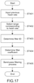
- FIG. 17 is a flowchart showing an example of a filtering procedure.
- the immediately-preceding heart rate included in the heart-rate information item is input as the reference heart rate (Step 401 ).
- a range corresponding to the reference heart rate is selected from the first filter bank 62 (Step 402 ), and the filter ID is determined (Step 403 ).
- the filter coefficient is determined from the filter ID (Step 404 ).
- the determined filter coefficient (hereinafter, described as “corresponding filter coefficient”) is set as a filter coefficient of the filtering unit 61 .
- the band-pass filter that allows the frequency band including the reference heart rate to pass therethrough is set in the filtering unit 61 .
- the pass band of the corresponding filter coefficient corresponds to a first frequency band.
- the adaptive-band-pass-filter processing unit 60 selects the corresponding filter coefficient corresponding to the reference heart rate. Then, the pass band of the corresponding filter coefficient is set as a frequency band of the filtering unit. In other words, the adaptive-band-pass-filter processing unit 60 sets the pass band on the basis of the heart-rate information item.
- the filtering unit 61 executes the band-pass filtering process on the reference signal (Step 405 ).
- the frequency component within the pass band is allowed to pass.
- the immediately-preceding heart rate reference heart rate
- the surrounding band components including the heart-rate component are allowed to pass, and the other bands are removed.
- the heart-rate component has been contained in the filtered second error signal (heart-rate component signal), and the non-heart-rate component has been removed therefrom.
- a heart-rate fluctuation and a heart-rate trend are detected (Step 107 ).
- the heart-rate fluctuation is detected by the heart-rate-fluctuation detection unit 70 shown in FIG. 2 .
- the heart-rate trend is detected by a heart-rate-trend detection unit 80 shown in FIG. 2 .
- FIG. 18 is a block diagram showing a configuration example of the heart-rate-fluctuation detection unit 70 .
- the heart-rate-fluctuation detection unit 70 includes a buffer 71 , a peak detection unit 72 , an instantaneous-heart-rate/reliability calculation unit 73 , a resampling unit 74 , and a post-processing filter unit 75 .
- the peak detection unit 72 detects a peak position of the pulsation from the pulse-wave signal that has been reduced in body-motion noise. As shown in FIG. 18 , a maximum value, a minimum value, a local maximum value, and a local minimum value of the pulse-wave signal are input to the peak detection unit 72 via the buffer 71 . In the following, an example of peak-position detection by local-maximum-value detection is described.
- the contact state of the first PPG sensor 12 may change to modulate an intensity of the pulse-wave signal.
- the peak position of the pulsation may fail to be detected. Further, there is a risk that a false peak due to the body motion is falsely detected as the peak of the pulsation.
- the threshold “th” of the peak intensity is adaptively controlled in accordance with the intensity of the pulse-wave signal.
- the peak position can be detected.
- any of or a plurality of the following processing examples are executed alone or in combination.
- Calculating a concavity of a current local-maximum value specifically, a level difference from an immediately-preceding local minimum value and an immediately-preceding local maximum value, and performing determination on the basis of the threshold.
- the heart-rate-fluctuation detection unit 70 and the heart-rate-trend detection unit 80 may be cascaded.
- the instantaneous-heart-rate/reliability calculation unit 73 detects the instantaneous heart rate and its reliability.
- the instantaneous heart rate which means a momentary heart rate, is calculated, for example, as a value by multiplying an inverse of a time interval at the peak position (position of the local maximum value) by 60 (seconds).
- the heart-rate fluctuation can be measured with high accuracy in real time during, for example, heart-rate training.
- the “heart rate” refers to the number of heartbeats at a time when a heart pumps out blood to an entirety of a body
- the “pulse rate” refers to the number of the pulsations (pulses) that occur in arteries. It is said that, as long as arrhythmia, pulse deficits, and the like do not occur, the “heart rate” and the “pulse rate” are substantially equal to each other.
- the results of the measurement by the heart-rate measurement device 200 are described, for example, as the heart-rate fluctuation, the heart-rate trend, and the instantaneous heart rate.
- the measurement results may be described, for example, as a pulse fluctuation, a pulse trend, and an instantaneous pulse rate.
- the present technology is applicable, for example, also to a case where the “pulse rate” being the pulsations in the arteries at the measurement site is used as a parameter different from the “heart rate.”
- the reliability is calculated on the basis of, for example, the level difference between the local maximum value and the local minimum value. As the level difference between the local maximum value detected as the peak and the immediately-preceding (or immediately-subsequent) local minimum value, that is, a concavity of the local maximum value becomes larger, the reliability to be given becomes higher.
- the reliability may be calculated by other methods.
- the post-processing filter unit 75 executes a post-process thereon.
- the post-processing filter unit 75 is constituted by an IIR filter and a feedback-factor calculation unit, and a feedback factor of this IIR filter is controlled as appropriate.
- the first noise-reduction processing unit 30 , the second noise-reduction processing unit 40 , and the peak detection unit 72 may fail to completely remove the noise.
- an outlier of a temporal change of the instantaneous heart rate may be generated.
- time correlation of the instantaneous heart rate is significantly high.
- adjustment of increasing the feedback factor of the IIR filter of the post-processing filter unit 75 (for example, to a value close to 1.0) is performed.
- a previous instantaneous heart rate can be subjected as it is to an extrapolation process, whereby the false detection can be corrected (reduced).
- FIG. 19 is a block diagram showing a configuration example of the heart-rate-trend detection unit 80 .
- the heart-rate-trend detection unit 80 includes buffers 81 a and 81 b , an autocorrelation analysis unit 82 , a stabilization processing unit 83 , a filter-coefficient control unit 84 , a trend detection unit 85 , and a resampling unit 86 .
- the autocorrelation analysis unit 82 performs, at each sampling timing, autocorrelation analysis with respect to the pulse-wave signal that has been reduced in body-motion noise. Although there are various methods of calculating an autocorrelation function, a normalized autocorrelation function is used in the analysis to be performed in this embodiment.
- the stabilization processing unit 83 performs weighting addition of a previous autocorrelation function stored in the buffer 81 b with respect to an autocorrelation function at a current timing, thereby stabilizing the autocorrelation function.
- a weighting parameter is determined from the acceleration signal (body-motion signal) by the filter-coefficient control unit 84 .
- the trend detection unit 85 detects, from the stabilized autocorrelation function, lags ⁇ during which an autocorrelation value consecutively increases. In this way, the trend detection unit 85 calculates periods of the pulse-wave signal as the heart-rate trend. On the basis of this heart-rate trend, the heart rate and its reliability are calculated. Note that, this heart rate is calculated on the basis of the heart-rate trend (periods of the pulse-wave signal), and hence is different from the instantaneous heart rate.
- the reliability is calculated on the basis of, for example, normalized autocorrelation values at positions of the specified lags ⁇ , that is, the autocorrelation values in the detected periods. As the autocorrelation value becomes larger, the reliability to be given becomes higher. The reliability may be calculated by other methods. After resampling to 1 Hz by the resampling unit 86 , the heart rate and its reliability are output.
- the heart-rate-fluctuation detection unit 70 and the heart-rate-trend detection unit 80 correspond to a plurality of calculation units that calculate heart-rate-candidate information items and their reliabilities on the basis of the pulse-wave signal. Further, these detection units may be referred to also as heart-rate estimators. In addition, the instantaneous heart rate that is calculated by the peak detection, and the heart rate that is calculated by the autocorrelation analysis each correspond to the heart-rate-candidate information item.
- the number of the calculation units that calculate the heart-rate-candidate information items on the basis of the pulse-wave signal, and algorithms for the calculation, and the like are not limited, and may be set as appropriate. Further, the heart rate is typically calculated as the heart-rate-candidate information item, but different information items may be calculated.
- the integration processing unit 90 shown in FIG. 2 executes an integration process (Step 108 ). Specifically, on the basis of the instantaneous heart rate and the heart rate that are output as the heart-rate-candidate information items from each of the heart-rate-fluctuation detection unit 70 and the heart-rate-trend detection unit 80 , and on the basis of their reliabilities, the integration processing unit 90 outputs the heart-rate information item. In other words, the integration processing unit 90 outputs a final heart-rate information item on the basis of output results from the plurality of heart-rate estimators and reliabilities of these results. In this embodiment, the integration processing unit 90 functions as an output unit.
- a heart-rate-candidate information item with a highest reliability As an example of methods of outputting the final heart-rate information item, there may be mentioned a heart-rate-candidate information item with a highest reliability. Specifically, the reliability of the instantaneous heart rate and the reliability of the heart rate based on the heart-rate trend are compared to each other, and then the heart rate with higher one of the reliabilities is output as the final heart-rate information item.
- the final heart-rate information item may be calculated by multidimensional vectorization of the reliabilities calculated by the plurality of heart-rate estimators, and with use of, for example, a discriminator constituted by a neural network.
- a data item of an actual heart rate is obtained by measurement with, for example, an electrocardiograph.
- the multidimensional vectors calculated by the plurality of heart-rate estimators from the plurality of pulse-wave signals (pulse-wave signal and reference pulse-wave signal) and the acceleration signal (body-motion signal) that are measured simultaneously with each other being input data items.
- the integration processing unit 90 determines whether or not to perform a fallback. For example, when both the reliability of the instantaneous heart rate and the reliability of the heart rate based on the heart-rate trend are lower than respective preset thresholds, the fallback is performed. As the fallback, for example, an immediately-preceding heart rate is pre-held, and output as the final heart-rate information item. With this, an output of the heart-rate information item with low reliability is prevented, and at the same time, the heart-rate measurement can be continued. Note that, an operation of the fallback is not particularly limited.
- the fallback operation may be performed. For example, when not only the reliabilities calculated by the first noise-reduction processing unit 30 and the second noise-reduction processing unit 40 , but also the reliabilities calculated by the heart-rate-fluctuation detection unit 70 and the heart-rate-trend detection unit 80 are low, the fallback is performed. Alternatively, when the reliabilities calculated by the first noise-reduction processing unit 30 and the second noise-reduction processing unit 40 are low, the fallback is performed irrespective of values of the reliabilities calculated by the two heart-rate estimators.
- the fallback is not performed even when both the reliabilities calculated by the two heart-rate estimators are low, and the heart-rate-candidate information item with higher one of the reliabilities is output.
- Such processes also may be executed.
- the pulse-wave signal may be saturated also when the feedback light intensity changes due to a change in shape of the arm in conjunction with the body motion.
- the light intensities of light-emitting elements can be actively controlled (details of the light-intensity control are described below).
- the fallback may be performed. Alternatively, whether or not the fallback operation needs to be performed may be determined on the basis of the reliabilities calculated by the body-motion analysis unit 20 , or of a calculation value of the autocorrelation analysis by the heart-rate-trend detection unit 80 .
- the stabilization processing unit 100 stabilizes the heart rate to be output as the final heart-rate information item. For example, the stabilization processing unit 100 reduces the false detection of the instantaneous heart rate due to the body-motion noises that cannot be removed by the first noise-reduction processing unit 30 , the second noise-reduction processing unit 40 , and the peak detection.
- the configuration, for example, of the stabilization processing unit 100 is not particularly limited.
- the final heart-rate information item to be output from the stabilization processing unit 100 is fed back to the reference-signal generating unit 50 and the adaptive-band-pass-filter processing unit 60 .
- a method, for example, of the feedback is not limited, and processes in accordance with types of the heart rate to be fed back may be executed as appropriate.
- a consecutive heart rate that follows a previous trend is fed back.
- a value output from the stabilization processing unit 100 is fed back as it is to the first filter bank 62 and the second filter bank 54 .
- the instantaneous heart rate detected by the heart-rate-fluctuation detection unit 70 is output, the instantaneous heart rate that abruptly changes is subjected, for example, to the smoothing process, and then fed back to the filter banks. In this way, filtering is performed stably in accordance with the feedback of the heart rate.
- the light-intensity control unit 110 shown in FIG. 2 controls the light intensity of the light beams in the first wavelength band, which are emitted from the first light-emitting unit of the first PPG sensor 12 (hereinafter, abridged as “light emission intensity”).
- the light-intensity control unit 110 corrects a light-intensity control value being a parameter for controlling the light emission intensity in accordance with a received-light intensity for the pulse-wave signal.
- FIG. 20 is a block diagram showing a configuration example of the light-intensity control unit.
- the light-intensity control unit 110 includes a light-intensity setting unit 111 , a light-intensity determination unit 112 , a parameter setting unit 113 , and an intensity calculation unit 114 .
- the light-intensity setting value for the first PPG sensor 12 is input to the light-intensity setting unit 111 .
- the pulse-wave signal (heart-rate component signal) output from the adaptive-band-pass-filter processing unit 60 is input to the intensity calculation unit 114 .
- the pulse-wave signal contains an AC component that oscillates in periods equivalent to those of the heartbeat (hereinafter, abridged as “AC heart-rate component”), and other components.
- the intensity calculation unit 114 calculates a heart-rate intensity being an intensity of the AC heart-rate component, and a pulse-wave-signal intensity being the intensity of the pulse-wave signal itself.
- the heart-rate intensity is an intensity of a signal based on the heartbeat, which is contained in the pulse-wave signal.
- the pulse-wave-signal intensity corresponds to an intensity of a baseline of the pulse-wave signal, which is a value in accordance, for example, with the feedback light intensity to be detected by the first light-receiving unit of the first PPG sensor 12 .
- a value of the heart-rate intensity is smaller than that of the pulse-wave-signal intensity.
- Calculation methods for example, for the heart-rate intensity and the pulse-wave-signal intensity are not limited. For example, an amplitude or an effective value of the AC heart-rate component is calculated as the heart-rate intensity. Further, as the pulse-wave-signal intensity, for example, an average value of the pulse-wave signal within a predetermined time period is calculated.
- a target value (“target”) of the feedback light intensity, and a range in which reliable feedback-light intensities are obtained (“range”) are determined.
- the “target” and the “range” each corresponding to the light-intensity control value are parameters to be used in the light-intensity determination unit 112 .
- the feedback light intensity herein refers to the intensity of the light beam detected by the first light-receiving unit of the first PPG sensor 12 .
- the light beams to be detected by the first light-receiving unit may include not only the reflected light beams among the light beams in the first wavelength band, but also the external light beams and the stray light beams.
- the first PPG sensor 12 outputs the pulse-wave signal with an intensity corresponding to the detected feedback-light intensity.
- the intensity of the pulse-wave signal output from the adaptive-band-pass-filter processing unit (pulse-wave-signal intensity) is used as an index that indicates the feedback light intensity.
- the index that indicates the feedback light intensity is not limited thereto.
- the first PPG sensor 12 may directly measure the feedback light intensity.
- a pulse-wave signal which is immediately after being output from the first PPG sensor 12 and has not been subjected, for example, to the filtering processes, may be used as the index that indicates the feedback light intensity.
- FIG. 21 is a flowchart showing an example of the light-intensity control.
- the parameter setting unit 113 corrects a range of the feedback light intensity in accordance with the pulse-wave signal (Step 501 ). Specifically, the parameter setting unit 113 determines the light-intensity control values (“target” and “range”) on the basis of the heart-rate intensity that the intensity calculation unit 114 has calculated from the pulse-wave signal. Details of a method of determining the light intensity are described below.
- the light-intensity determination unit 112 determines whether or not the feedback light intensity is out of the range (Step 502 ). When the pulse-wave intensity signal calculated by the intensity calculation unit 114 falls within the feedback-light-intensity range (“range”) determined in Step 501 (No in Step 502 ), the light-intensity control is ended. When the pulse-wave intensity signal does not fall within the “range” (Yes in Step 502 ), the light emission intensity is controlled.
- the light-intensity setting unit 111 performs the light-intensity control (Step 503 ). In order that the feedback light intensity reaches the target value (“target”) determined in Step 501 , the light-intensity setting unit 111 performs proportional control (P control) on the light emission intensity of the first PPG sensor 12 . For example, in accordance with a difference between the pulse-wave intensity and the “target,” an increase or a decrease of the light emission intensity is calculated. On the basis of a current light-intensity setting value, and of the calculated increase or the calculated decrease, a new light-intensity setting value is calculated. Then, this new light-intensity setting value is output to the first PPG sensor 12 .
- P control proportional control
- the light-intensity determination unit 112 determines whether or not a monitored value of the feedback light intensity is equal to the target value (“target”) (Step 504 ).
- This monitored value of the feedback light intensity is the pulse-wave-signal intensity calculated by the intensity calculation unit after the light-intensity control in Step 503 .
- the processes of Step 501 and subsequent Steps are re-executed to continue the light-intensity control.
- the light-intensity determination unit 112 determines that the pulse-wave-signal intensity is equal to the “target” (Yes in Step 504 )
- the light-intensity control is ended.
- the light-intensity control values (correction parameters) to be used in the light-intensity determination unit 112 is determined.
- a reference range in which reliable feedback-light intensities are obtained (“range 0 ”), and a reference target value of the feedback light intensity (“target 0 ”) are set as the reference light-intensity control values.
- the light-intensity control values are determined by gain-multiplying the fixed parameters “a,” “b,” and “c.”
- the gains are calculated in accordance with the intensity of the AC heart-rate component (heart-rate intensity) PPG ac , which is calculated by the intensity calculation unit 114 , and a threshold PPG th of the heart-rate intensity.
- FIG. 22 is a graph showing an example of the gains to be used for the correction of the range of the feedback light intensity.
- the abscissa axis and the ordinate axis of the graph respectively represent the heart-rate intensities and the gains.
- the relationship between the gains and the heart-rate intensities is linear, and exhibits a negative slope. Further, when the heart-rate intensity PPG ac and the threshold PPG th are equal to each other, a value of the gain is one.
- the heart-rate intensity PPG ac exceeds the threshold PPG th , it is determined that a signal with a sufficiently high reliability has been detected, and a gain value less than one is selected.
- the light-intensity range range in which reliable feedback-light intensities are obtained
- the target light-intensity value target value of the feedback light intensity
- the heart-rate intensity PPG ac is less than the threshold PPG th , it is determined that a signal with a low reliability has been detected, and a gain value more than one is selected. Thus, the light-intensity range and the target light-intensity value are increased by being gain-multiplied.
- the correction parameters are calculated in consideration, for example, of a dynamic range of the first light-receiving unit of the first PPG sensor 12 .
- a dynamic range of the first light-receiving unit of the first PPG sensor 12 For example, light beams exceeding an upper limit of the dynamic range cause deterioration of the light receiving unit. Meanwhile, when the light intensity is excessively low, it is difficult to detect a pulse-wave component.
- a maximum allowable value and a minimum allowable value of each of the correction parameters are set in advance, and the clipping process is executed such that the correction parameters fall within ranges therebetween.
- the maximum value and the minimum value of each of the correction parameters are set as appropriate in accordance, for example, with characteristics of the first light-receiving unit.
- the fixed parameter “a” is stored in advance together with a maximum value a max and a minimum value a min .
- the clipping process is executed to set an upper limit of a′ to a max when the fixed parameter “a” exceeds the maximum value a max by being gain-multiplied, and to set a lower limit of a′ to a min when the fixed parameter “a” falls below the minimum value a min by being gain-multiplied.
- the fixed parameters “b” and “c” are also stored in advance together with their maximum values and minimum values, and similarly subjected to the clipping processes.
- the clipping processes to be executed on the parameters are expressed as follows.
- a ′ clip(gain ⁇ a,a min ,a max )
- b ′ clip(gain ⁇ b,b min ,b max )
- c ′ clip(gain ⁇ c,c min ,c max )
- the pulse-wave-signal intensity is determined on the basis of the “range” and the “target” that have set by the light-intensity determination unit 112 .
- the light-intensity setting value calculated in Step 503 is output also to the body-motion analysis unit 20 shown in FIG. 2 .
- the body-motion analysis unit 20 is allowed to calculate the reliabilities of, for example, the pulse-wave signal on the basis of a latest light-intensity setting value. Note that, when the light-intensity control and the like are not performed, a light-intensity setting value output, for example, from the first PPG sensor 12 is output as it is to the body-motion analysis unit 20 .
- the gain values are set on the basis of a linear function.
- the gain values may be set, for example, by using a line chart or curve functions such as a Sigmoid function.
- the gain values given to the fixed parameters “a,” “b,” and “c” are equal to each other.
- individual gain values may be given respectively to the fixed parameters by respectively setting different gain-value control graphs.
- the range of the feedback light intensity that the pulse-wave sensor detects is corrected, and the light emission intensity is controlled.
- adjustment of the value of the feedback light intensity to a constant value by methods including using the fixed parameters, such as the P control that is generally performed in the field of a control engineering, is performed, but it is difficult to properly maintain other parameters thereby.
- the range of the feedback light intensity can be adjusted. With this, the light intensity and the like can be controlled such that the parameters other than the feedback light intensity (such as heart-rate intensity) reach appropriate values.
- the adaptive-band-pass-filter processing unit 60 filters the pulse-wave signal on the basis of previous heart-rate information items. Then, highly accurate heart-rate information items are output on the basis of the filtered pulse-wave signal. In this way, highly accurate heart-rate measurement can be performed.
- body motions occur during activities of the user.
- body motions occur in a daily environment
- body-motion noises over a wide range from a low-frequency band to a high-frequency band occur.
- the user does the variety of activities in his/her daily environment, and hence body-motion noises occur in various patterns and with various intensities, specifically, a periodic body-motion noise and a non-periodic body-motion noise occur.
- the body-motion noises of various types are contained in the output from, for example, the pulse-wave sensor.
- an S/N ratio of the heart-rate component decreases, which may be factors that cause errors in detecting the heartbeat.
- the adaptive-band-pass-filter processing unit 60 functions as the band-pass filter.
- the pass band of the band-pass filter is set on the basis of the heart rate that is immediately-previously output from the heart-rate measurement device 200 (stabilization processing unit 100 ).
- the band-pass filter that adaptively operates in accordance, for example, with the heart-rate fluctuation is provided.
- a frequency band relating to a heart rate to be measured can be extracted.
- a signal in which the S/N ratio of the heart-rate component is kept high can be output.
- the reference signal filtered by the adaptive-band-elimination-filter processing unit 52 being the second filter unit is generated.
- the reference pulse-wave signal from the second PPG sensor 13 is used as the reference signal.
- the reference pulse-wave signal contains not only a lot of information items of the body-motion noise that is caused by the movements of the fingers and the wrist, but also the heart-rate component.
- the heart-rate component is also weakened at the same time, resulting in a decrease of the S/N ratio of the heart-rate component.
- the adaptive-band-elimination-filter processing unit 52 functions as the band-elimination filter.
- the stop band of the band-elimination filter is set on the basis of the fed-back heart rate.
- the peak position of the pulsation can be detected.
- the heart-rate fluctuation can be detected with high accuracy.
- the autocorrelation analysis by the heart-rate-trend detection unit 80 periodicity of the pulse wave is utilized.
- the risk that the peak due to the residual noise is falsely detected as the peak position of the pulsation can be sufficiently suppressed. With this, significantly-high noise resistance is obtained.
- the final heart-rate information item is calculated.
- heart-rate detection in which disadvantages of the units are compensated each other can be performed, and hence heart-rate measurement with accuracy significantly higher than that in a case of using a single heart-rate estimator is performed.
- the PPG heart-rate sensor is capable of measuring the pulse-wave signal with relatively high accuracy in the resting state, once the measurement site moves, the body-motion noises are generated in the monitoring signal.
- the body-motion noises in the wristband-type heart-rate sensor entry of unnecessary reflection from a surface of the skin, and the entry of the external light beams that have propagated under the skin may be mentioned, which are caused by the change of the contact state of the PPG sensor and the measurement site.
- the false signals may be generated by the blood-flow changes due to the movement of the measurement site, and a fluctuation of a light absorption rate may be caused by the deformation of the tissues under the skin due to the movements of the fingers and the wrist (movements of bones).
- a combined factor of these main factors causes mixing of a false peak signal into the pulse-wave signal, it is difficult to distinguish which peak corresponds to the peak position of the pulsation.
- a risk that an erroneous pulse rate is detected.
- the adaptive filtering is a technique for automatically calculating a filter coefficient (W) that minimizes power of an error signal (e) at a time when a monitoring signal (d) and an input signal (X) are given is minimized.
- W filter coefficient
- a noise mixed with the monitoring signal can be separated by referring to the input signal, specifically, to a signal having high correlation with the noise.
- the first noise-reduction processing unit 30 reduces the arm movement noise
- the second noise-reduction processing unit 40 reduces the finger-and-wrist movement noise.
- the filtering by the adaptive-band-pass-filter processing unit 60 can be performed in combination, a noise due to a non-cyclic movement of the arm at times other than the walking and the running also can be reduced.
- a noise due to a non-cyclic movement of the arm at times other than the walking and the running also can be reduced.
- the noise reduction processes in which the false detection is prevented can be executed.
- the heart-rate fluctuation in the daily life can be constantly measured with high accuracy.
- the light-intensity control unit 110 controls the light emission intensity of the first PPG sensor 12 on the basis of the heart-rate intensity. Specifically, when a sufficiently high heart-rate intensity has been detected, the light emission intensity is reduced such that the heart-rate intensity is moderated. In contrast, when the heart-rate intensity is low, the light emission intensity is increased to perform adjustment to an appropriate heart-rate intensity. With this, the appropriate heart-rate intensity can be maintained while suppressing, for example, unnecessary light-emission. Thus, both robustness in detection of the heart-rate fluctuation and low power consumption can be achieved.
- Frequency analysis techniques also have been known as techniques for stably calculating the pulse rate. Specifically, by performing frequency analysis with respect to the pulse-wave signal after the noise reduction processes, a frequency at which a maximum spectrum intensity is obtained is determined as the pulse rate.
- the frequency analysis techniques have a problem in principle with accuracy in estimating the heart-rate fluctuation in a low-heart-rate band. In the heart-rate measurement device 200 according to this embodiment, even the heart-rate fluctuation in the low-heart-rate band can be calculated with high accuracy.
- the heart-rate measurement device 200 is described as one embodiment of the vital sign processing device according to the present technology.
- the embodiment of the vital sign processing device according to the present technology is not limited thereto, and encompasses arbitrary devices including the pulsimeter.
- arbitrary electronic apparatuses specifically, wearable devices of various types such as a headband type, a neckband type, and a belt type, arbitrary PDAs (Personal Digital Assistants) such as a smartphone and a tablet terminal, medical devices, game devices, and home electric appliances may be configured as the vital sign processing device according to the present technology.
- the pulse-wave signal (second error signal) from which the body-motion noises have been separated by the first noise-reduction processing unit 30 and the second noise-reduction processing unit 40 is filtered by the adaptive-band-pass-filter processing unit 60 provided in a subsequent stage.
- the adaptive-band-pass-filter processing unit is provided in a stage preceding the noise-reduction processing units.
- FIG. 23 is a block diagram showing a functional configuration example of a controller according to the second embodiment.
- an adaptive-band-pass-filter processing unit 120 is provided in a stage preceding the first noise-reduction processing unit 30 (arm-movement-noise-reduction processing unit 30 ) and the reference-signal generating unit 50 .
- the pulse-wave signal (PPG (green)) output from the first PPG sensor 12 , the reference pulse-wave signal (PPG (red)) output from the second PPG sensor 13 , and the body-motion signal (acceleration) output from the acceleration sensor 14 are input to the adaptive-band-pass-filter processing unit 120 . Further, the heart-rate information item (reference heart rate) output from the stabilization processing unit 100 is input to the adaptive-band-pass-filter processing unit 120 .
- FIG. 24 is a flowchart showing another example of outputting the heart-rate information item.
- the band-pass filters 16 a to 16 c execute the band-pass filtering processes (Step 601 ).
- the body-motion analysis unit 20 analyzes the body-motion intensity at the measurement site (Step 602 ).
- the adaptive-band-pass-filter processing unit 120 shown in FIG. 23 performs filtering on the basis of an immediately-preceding heart rate (Step 603 ).
- the adaptive-band-pass-filter processing unit 120 executes the processes of filtering, through the respective band-pass filters, the pulse-wave signal to be input, the reference pulse-wave signal to be input, and the body-motion signal to be input.
- the band-pass filters allow the surrounding band including the reference heart rate (first frequency band) to pass therethrough, and remove the other frequency bands.
- a plurality of band-pass filters are provided correspondingly to the signals to be input, and these signals are respectively filtered thereby.
- the non-heart-rate components are removed from the pulse-wave signal, the body-motion signal, and the reference pulse-wave signal output from the band-pass filters 16 a to 16 c .
- the signals that have passed through the band-pass filters are transmitted to the blocks in the subsequent stage.
- the filtered reference signal and the filtered body-motion signal are output to the first noise-reduction processing unit 30 .
- all the filtered pulse-wave signal, the filtered body-motion signal, and the filtered reference pulse-wave signal are output to the reference-signal generating unit 50 .
- the first noise-reduction processing unit 30 shown in FIG. 23 executes the arm-movement-noise reduction process (Step 604 ).
- the first noise-reduction processing unit 30 reduces the arm movement noise in the pulse-wave signal from which the non-heart-rate component has been removed, and then outputs the first error signal (pulse-wave signal).
- the reference-signal generating unit 50 generates the reference signal (Step 605 ).
- the reference-signal generating unit 50 performs, for example, the main-component analysis of the pulse-wave signal, the body-motion signal, and the reference pulse-wave signal from each of which the non-heart-rate component has been removed. On the basis of this analysis, the reference signal that has high correlation with the finger-and-wrist movement noise is generated.
- the adaptive-band-elimination-filter processing unit filters the reference signal with reference, for example, to the second filter bank. With this, the heart-rate component is removed from the reference signal. As a result, the reference signal that has high correlation with the finger-and-wrist movement noise and low correlation with the heart-rate component being a main signal is generated. The filtered reference signal is output to the adaptive filter of the second noise-reduction processing unit.
- the second noise-reduction processing unit 40 executes the finger-and-wrist-movement-noise reduction process (Step 606 ).
- the reference signal filtered by the second filter unit is input to the adaptive filter.
- the output value of the adaptive filter is subtracted from the first error signal, and then the second error signal (pulse-wave signal) is output.
- the second error signal is a signal in which both the body-motion noises, specifically, the arm movement noise and the finger-and-wrist movement noise have been reduced and from which the non-heart-rate component has been removed.
- the heart-rate fluctuation and the heart-rate trend are detected (Step 607 ).
- the heart-rate-fluctuation detection unit 70 and the heart-rate-trend detection unit 80 detect the instantaneous heart rate and the heart rate based on the heart-rate trend.
- the integration processing unit 90 executes the integration process (Step 608 ), and then the stabilization processing unit 100 outputs the final heart rate.
- the final heart rate is fed back as appropriate to the adaptive-band-pass-filter processing unit 120 and the reference-signal generating unit 50 .
- the adaptive-band-pass-filter processing unit 120 removes the non-heart-rate component from each of the signals.
- the processes can be executed intensively on the band including the heart-rate component.
- the processes in the subsequent stages are allowed to progress with higher accuracy than that at a time when a wide frequency band is processed.
- the number of calculations to be performed can be reduced, and hence processing time periods, for example, can be shortened.
- the reference signal is generated via the adaptive-band-pass-filter processing unit and the adaptive-band-elimination-filter processing unit (first filter unit and second filter unit).
- the correlation between the heart-rate component being the main signal to be extracted and the reference signal is minimized.
- the noises due to the body motions can be separated.
- accuracy of the calculations for separating the body-motion noises is increased, and hence a signal containing an emphasized heart-rate component can be generated. In this way, highly accurate heart-rate measurement can be performed.
- the reference signal generated by the signal analysis unit of the reference-signal generating unit is filtered by the adaptive-band-elimination-filter processing unit (second filter unit).
- the order of removing the heart-rate component from the reference signal is not limited as long as the heart-rate component is removed at an arbitrary timing before the reference signal is used for the separation of the body-motion noises.
- the second filter unit may be provided in a stage preceding the signal analysis unit.
- the signal analysis unit may generate the reference signal on the basis of these filtered signals.
- the filtering of the reference signal encompasses the generation of the reference signal from the filtered pulse-wave signal, the filtered reference pulse-wave signal, and the filtered body-motion signal.
- the first PPG sensor 12 is provided to generate the pulse-wave signal
- the second PPG sensor 13 is provided to generate the reference pulse-wave signal for generating the reference signal.
- either one of the pulse-wave-candidate signals to be output from the first PPG sensor 12 and the second PPG sensor 13 may be selected as appropriate, and output as the pulse-wave signal from which the heart rate is calculated.
- a first pulse-wave sensor that generates the pulse-wave signal to be subjected to the noise reduction processes may be predetermined from a plurality of pulse-wave sensors, or the first pulse-wave sensor may be selected as appropriate from the plurality of pulse-wave sensors. By selecting the first pulse-wave sensor each time, a signal with a most intense pulse-wave component can be selected. With this, highly accurate heart-rate measurement can be performed.
- a vital sign processing device including:
- a pulse-wave sensor unit that outputs a pulse-wave signal
- an output unit that outputs a heart-rate information item on the basis of the output pulse-wave signal
- the first filter unit sets the first frequency band on the basis of a heart rate included in the heart-rate information item.
- the output unit outputs the heart-rate information item on the basis of the heart-rate-candidate information item and the reliability of the heart-rate-candidate information item, the heart-rate-candidate information item and the reliability being calculated by each of the plurality of calculation units.
- each of the plurality of calculation units calculates the heart-rate-candidate information item and the reliability of the heart-rate-candidate information item on the basis of the pulse-wave signal filtered by the first filter unit.
- the vital sign processing device according to Item (4) or (5), further including:
- a body-motion sensor that outputs a body-motion signal
- noise-reduction processing unit that separates, on the basis of the body-motion signal, a body-motion noise from the pulse-wave signal output from the pulse-wave sensor unit, in which
- each of the plurality of calculation units calculates the heart-rate-candidate information item and the reliability of the heart-rate-candidate information item on the basis of the pulse-wave signal from which the body-motion noise has been separated.
- the first filter unit filters the pulse-wave signal from which the body-motion noise has been separated by the noise-reduction processing unit.
- a generating unit that generates, on the basis of the plurality of pulse-wave-candidate signals that are generated by the plurality of pulse-wave sensors, a reference signal for separating the body-motion noise, in which
- the second filter unit sets the second frequency band on the basis of a heart rate included in the heart-rate information item.
- the second filter unit filters at least one of the plurality of pulse-wave-candidate signals or the body-motion signal
- the generating unit generates the reference signal on the basis of an output from the second filter unit.
- the generating unit generates the reference signal on the basis of the plurality of pulse-wave-candidate signals filtered by the first filter unit, and
- the noise-reduction processing unit outputs an error signal obtained by subtraction of the output value of the adaptive filter from the pulse-wave signal filtered by the first filter unit.
- the plurality of pulse-wave sensors include a pulse-wave-signal pulse-wave sensor that generates the pulse-wave signal by emitting light beams in a predetermined wavelength band and then detecting a reflected light beam among the light beams in the predetermined wavelength band, and
- the vital sign processing device further includes
- the light-intensity control unit controls the light intensities of the pulse-wave-signal pulse-wave sensor
- the light-intensity control unit sets, on the basis of the intensity of the heart-rate signal, at least one of
Landscapes
- Health & Medical Sciences (AREA)
- Life Sciences & Earth Sciences (AREA)
- Engineering & Computer Science (AREA)
- Signal Processing (AREA)
- Surgery (AREA)
- Medical Informatics (AREA)
- Veterinary Medicine (AREA)
- Physics & Mathematics (AREA)
- Public Health (AREA)
- Biophysics (AREA)
- Pathology (AREA)
- Biomedical Technology (AREA)
- Heart & Thoracic Surgery (AREA)
- General Health & Medical Sciences (AREA)
- Molecular Biology (AREA)
- Animal Behavior & Ethology (AREA)
- Physiology (AREA)
- Artificial Intelligence (AREA)
- Psychiatry (AREA)
- Computer Vision & Pattern Recognition (AREA)
- Cardiology (AREA)
- Power Engineering (AREA)
- Measuring Pulse, Heart Rate, Blood Pressure Or Blood Flow (AREA)
Abstract
Description
- Patent Literature 1: Japanese Patent Application Laid-open No. 11-276448
th=vmin+α·(vmax−vmin)
0<α<1
a′=clip(gain×a,a min ,a max)
b′=clip(gain×b,b min ,b max)
c′=clip(gain×c,c min ,c max)
-
- that sets a first frequency band on the basis of the output heart-rate information item, and
- that allows the set first frequency band of the pulse-wave signal to pass through the first filter unit.
(2) The vital sign processing device according to Item (1), in which
-
- includes a first filter bank including a plurality of band-pass filters, and
- selects, on the basis of the heart rate and from the first filter bank, a filter that allows the first frequency band to pass through the filter.
(4) The vital sign processing device according to any one of Items (1) to (3), further including
-
- includes a plurality of pulse-wave sensors, and
- outputs, as the pulse-wave signal, any one of a plurality of pulse-wave-candidate signals that are generated by the plurality of pulse-wave sensors.
(9) The vital sign processing device according to Item (8), further including
-
- includes an adaptive filter to which the reference signal is input as an input signal, and
- outputs an error signal obtained by subtraction of an output value of the adaptive filter from the pulse-wave signal.
(10) The vital sign processing device according to Item (9), further including
-
- that sets a second frequency band on the basis of the heart-rate information item output by the output unit, and
- that removes the set second frequency band of the reference signal.
(11) The vital sign processing device according to Item (10), in which
-
- includes a second filter bank including a plurality of band-elimination filters, and
- selects, on the basis of the heart rate and from the second filter bank, a filter that removes the second frequency band.
(13) The vital sign processing device according to any one of Items (10) to (12), in which
-
- filters the reference signal generated by the generating unit, and
- then outputs the filtered reference signal to the adaptive filter.
(16) The vital sign processing device according to any one of Items (8) to (15), in which
-
- a light-intensity control unit that controls, on the basis of the pulse-wave signal filtered by the first filter unit, light intensities of the light beams in the predetermined wavelength band, the light beams being emitted from the pulse-wave-signal pulse-wave sensor.
(17) The vital sign processing device according to Item (16), in which
- a light-intensity control unit that controls, on the basis of the pulse-wave signal filtered by the first filter unit, light intensities of the light beams in the predetermined wavelength band, the light beams being emitted from the pulse-wave-signal pulse-wave sensor.
-
- on the basis of an intensity of a heart-rate signal contained in the pulse-wave signal filtered by the first filter unit, and
- on the basis of a feedback light intensity that is detected by the pulse-wave-signal pulse-wave sensor.
(18) The vital sign processing device according to Item (17), in which
-
- a target value,
- a lower-limit value, or
- an upper-limit value of the feedback light intensity that is detected by the pulse-wave-signal pulse-wave sensor.
- 10 sensor body portion
- 12 first PPG sensor
- 13 second PPG sensor
- 14 acceleration sensor
- 15, 17 controller
- 20 body-motion analysis unit
- 30 first noise-reduction processing unit
- 40 second noise-reduction processing unit
- 41 adaptive filter
- 50 reference-signal generating unit
- 52 adaptive-band-elimination-filter processing unit
- 54 second filter bank
- 60, 120 adaptive-band-pass-filter processing unit
- 62 first filter bank
- 70 heart-rate-fluctuation detection unit
- 80 heart-rate-trend detection unit
- 90 integration processing unit
- 100 stabilization processing unit
- 110 light-intensity control unit
- 200 heart-rate measurement device
Claims (18)
Applications Claiming Priority (4)
| Application Number | Priority Date | Filing Date | Title |
|---|---|---|---|
| JPJP2016-186623 | 2016-09-26 | ||
| JP2016-186623 | 2016-09-26 | ||
| JP2016186623 | 2016-09-26 | ||
| PCT/JP2017/030042 WO2018055969A1 (en) | 2016-09-26 | 2017-08-23 | Vital sign processing device, vital sign processing method, and information processing device |
Publications (2)
| Publication Number | Publication Date |
|---|---|
| US20210290092A1 US20210290092A1 (en) | 2021-09-23 |
| US11266321B2 true US11266321B2 (en) | 2022-03-08 |
Family
ID=61690882
Family Applications (1)
| Application Number | Title | Priority Date | Filing Date |
|---|---|---|---|
| US16/328,563 Active 2038-10-04 US11266321B2 (en) | 2016-09-26 | 2017-08-23 | Vital sign processing device, vital sign processing method, and information processing device |
Country Status (3)
| Country | Link |
|---|---|
| US (1) | US11266321B2 (en) |
| JP (1) | JP6933220B2 (en) |
| WO (1) | WO2018055969A1 (en) |
Cited By (1)
| Publication number | Priority date | Publication date | Assignee | Title |
|---|---|---|---|---|
| US20230000388A1 (en) * | 2020-03-11 | 2023-01-05 | Child Mind Institute, Inc. | Oxygen mask respirometer |
Families Citing this family (8)
| Publication number | Priority date | Publication date | Assignee | Title |
|---|---|---|---|---|
| WO2019200362A1 (en) * | 2018-04-12 | 2019-10-17 | The Regents Of The University Of California | Wearable multi-modal bio-sensing system |
| JP2020006014A (en) * | 2018-07-11 | 2020-01-16 | ソニー株式会社 | Biological information processing device and biological information processing method |
| EP4111974A1 (en) * | 2021-06-29 | 2023-01-04 | Koninklijke Philips N.V. | Physiological measurement device, method and program |
| CN115886744B (en) * | 2022-11-09 | 2025-06-03 | 广东粤港澳大湾区黄埔材料研究院 | A method and device for denoising motion pulse wave |
| CN116614730B (en) * | 2023-07-21 | 2023-09-22 | 乾坤环保股份有限公司 | Distributed data acquisition module and monitoring system for hydraulic engineering environment monitoring |
| AU2024298495A1 (en) * | 2023-07-26 | 2026-02-12 | Empatica Srl | Systems, devices, and methods for reducing signal noise |
| JP2025029499A (en) * | 2023-08-21 | 2025-03-06 | 積水ハウス株式会社 | HEART RATE DETECTION SYSTEM, HEART RATE DETECTION METHOD, AND PROGRAM |
| CN117204859B (en) * | 2023-11-09 | 2024-02-13 | 博睿康医疗科技(上海)有限公司 | Dry electrode brain electrical system with common mode noise channel and active noise reduction method for signals |
Citations (12)
| Publication number | Priority date | Publication date | Assignee | Title |
|---|---|---|---|---|
| EP0303502A1 (en) | 1987-08-14 | 1989-02-15 | Btg International Limited | Motion artefact rejection system for pulse oximeters |
| GB2208709A (en) | 1987-08-14 | 1989-04-12 | Nat Res Dev | Motion artefact rejection system for pulse oximeters |
| JPH02172443A (en) | 1988-12-23 | 1990-07-04 | Minolta Camera Co Ltd | Photoelectric pulse wave type oxymeter |
| JPH11276448A (en) | 1998-03-31 | 1999-10-12 | Seiko Epson Corp | Signal extraction device and signal extraction method |
| EP1757225A1 (en) | 2005-08-26 | 2007-02-28 | Nihon Kohden Corporation | Apparataus and method for measuring pulse rate |
| WO2007046283A1 (en) | 2005-10-18 | 2007-04-26 | Sharp Kabushiki Kaisha | Bioinformation acquiring device and bioinformation acquiring method |
| US20090227879A1 (en) | 2008-03-06 | 2009-09-10 | Fujitsu Limited | Pulse rate counting device, pulse rate counting method, and record medium therefor |
| US20110098582A1 (en) | 2009-10-27 | 2011-04-28 | Seiko Epson Corporation | Pulse detector and pulse detection method |
| JP2011115459A (en) | 2009-12-04 | 2011-06-16 | Nippon Soken Inc | Device and method for detecting biological information |
| US20120283581A1 (en) * | 2009-06-26 | 2012-11-08 | Gambro Lundia Ab | Devices, a computer program product and a method for data extraction |
| JP2014094043A (en) | 2012-11-07 | 2014-05-22 | Fujitsu Ltd | Heart rate estimation device, heart rate estimation method and program |
| US20150208964A1 (en) * | 2014-01-27 | 2015-07-30 | Covidien Lp | Systems and methods for determining respiration information |
-
2017
- 2017-08-23 WO PCT/JP2017/030042 patent/WO2018055969A1/en not_active Ceased
- 2017-08-23 JP JP2018540922A patent/JP6933220B2/en active Active
- 2017-08-23 US US16/328,563 patent/US11266321B2/en active Active
Patent Citations (18)
| Publication number | Priority date | Publication date | Assignee | Title |
|---|---|---|---|---|
| EP0303502A1 (en) | 1987-08-14 | 1989-02-15 | Btg International Limited | Motion artefact rejection system for pulse oximeters |
| GB2208709A (en) | 1987-08-14 | 1989-04-12 | Nat Res Dev | Motion artefact rejection system for pulse oximeters |
| JPH01153139A (en) | 1987-08-14 | 1989-06-15 | Natl Res Dev Corp | Pulse oximeter |
| US4955379A (en) | 1987-08-14 | 1990-09-11 | National Research Development Corporation | Motion artefact rejection system for pulse oximeters |
| JPH02172443A (en) | 1988-12-23 | 1990-07-04 | Minolta Camera Co Ltd | Photoelectric pulse wave type oxymeter |
| JPH11276448A (en) | 1998-03-31 | 1999-10-12 | Seiko Epson Corp | Signal extraction device and signal extraction method |
| US20070060827A1 (en) | 2005-08-26 | 2007-03-15 | Nihon Kohden Corporation | Apparatus and method for measuring pulse rate |
| JP2007054471A (en) | 2005-08-26 | 2007-03-08 | Nippon Koden Corp | Pulse rate measuring device and pulse rate measuring method |
| EP1757225A1 (en) | 2005-08-26 | 2007-02-28 | Nihon Kohden Corporation | Apparataus and method for measuring pulse rate |
| WO2007046283A1 (en) | 2005-10-18 | 2007-04-26 | Sharp Kabushiki Kaisha | Bioinformation acquiring device and bioinformation acquiring method |
| US20090227879A1 (en) | 2008-03-06 | 2009-09-10 | Fujitsu Limited | Pulse rate counting device, pulse rate counting method, and record medium therefor |
| JP2009207810A (en) | 2008-03-06 | 2009-09-17 | Fujitsu Ltd | Pulse rate measuring instrument, pulse rate measuring method, and program |
| US20120283581A1 (en) * | 2009-06-26 | 2012-11-08 | Gambro Lundia Ab | Devices, a computer program product and a method for data extraction |
| US20110098582A1 (en) | 2009-10-27 | 2011-04-28 | Seiko Epson Corporation | Pulse detector and pulse detection method |
| JP2011092236A (en) | 2009-10-27 | 2011-05-12 | Seiko Epson Corp | Pulse detector and pulse detection method |
| JP2011115459A (en) | 2009-12-04 | 2011-06-16 | Nippon Soken Inc | Device and method for detecting biological information |
| JP2014094043A (en) | 2012-11-07 | 2014-05-22 | Fujitsu Ltd | Heart rate estimation device, heart rate estimation method and program |
| US20150208964A1 (en) * | 2014-01-27 | 2015-07-30 | Covidien Lp | Systems and methods for determining respiration information |
Non-Patent Citations (2)
| Title |
|---|
| International Search Report and Written Opinion of PCT Application No. PCT/JP2017/030042, dated Nov. 37, 2017, 08 pages of ISRWO. |
| Office Action for JP Patent Application No. 2018-540922 dated Mar. 3, 2021, 03 pages of Office Action. |
Cited By (1)
| Publication number | Priority date | Publication date | Assignee | Title |
|---|---|---|---|---|
| US20230000388A1 (en) * | 2020-03-11 | 2023-01-05 | Child Mind Institute, Inc. | Oxygen mask respirometer |
Also Published As
| Publication number | Publication date |
|---|---|
| JP6933220B2 (en) | 2021-09-08 |
| US20210290092A1 (en) | 2021-09-23 |
| JPWO2018055969A1 (en) | 2019-07-11 |
| WO2018055969A1 (en) | 2018-03-29 |
Similar Documents
| Publication | Publication Date | Title |
|---|---|---|
| US11266321B2 (en) | Vital sign processing device, vital sign processing method, and information processing device | |
| US11311242B2 (en) | Biological information processing apparatus, biological information processing method, and information processing apparatus | |
| CN107949321B (en) | Time Domain Interference Removal and Improved Heart Rate Measurement Tracking Mechanism | |
| US20180146926A1 (en) | Noise reduction processing circuit and method, and biological information processing device and method | |
| US12369805B2 (en) | Motion detection and cancellation using ambient light | |
| US11129538B2 (en) | Heart rate estimation apparatus with state sequence optimization | |
| JP6211679B2 (en) | Heart rate detector | |
| Tanweer et al. | Motion artifact reduction from PPG signals during intense exercise using filtered X-LMS | |
| US20160206247A1 (en) | Adaptive motion correction in photoplethysmography using reference signals | |
| US20160120477A1 (en) | Biological-information processing apparatus and biological-information processing method | |
| JP6546661B2 (en) | Device and method for removing artifacts in physiological measurements | |
| JP6279098B2 (en) | Photoelectric pulse signal measuring method and measuring instrument | |
| US20170367657A1 (en) | Photoplethysmogram with motion artifact compensation | |
| CN116584911A (en) | A filtering method, device and system for pulse signal motion interference | |
| Lin et al. | Heart rate estimation using wrist-acquired photoplethysmography under different types of daily life motion artifact | |
| WO2018187895A1 (en) | Wearable device, method and device for self-adaptive filtering of motion interference | |
| WO2024062919A1 (en) | Signal processing device, signal processing method, program, and learning device | |
| US12178558B2 (en) | Biometric information processing apparatus and biometric information processing method | |
| CN120827358B (en) | Exercise heart rate acquisition method, exercise heart rate acquisition equipment and readable storage medium | |
| US20250120610A1 (en) | System and method for respiratory rate monitoring | |
| WO2025165707A1 (en) | Motion artifact mitigation in seismocardiography and gyrocardiography |
Legal Events
| Date | Code | Title | Description |
|---|---|---|---|
| AS | Assignment |
Owner name: SONY CORPORATION, JAPAN Free format text: ASSIGNMENT OF ASSIGNORS INTEREST;ASSIGNORS:HYODO, YASUHIDE;ISHIKAWA, TAKANORI;SIGNING DATES FROM 20190212 TO 20190213;REEL/FRAME:048446/0511 |
|
| FEPP | Fee payment procedure |
Free format text: ENTITY STATUS SET TO UNDISCOUNTED (ORIGINAL EVENT CODE: BIG.); ENTITY STATUS OF PATENT OWNER: LARGE ENTITY |
|
| STPP | Information on status: patent application and granting procedure in general |
Free format text: NON FINAL ACTION MAILED |
|
| STPP | Information on status: patent application and granting procedure in general |
Free format text: RESPONSE TO NON-FINAL OFFICE ACTION ENTERED AND FORWARDED TO EXAMINER |
|
| STPP | Information on status: patent application and granting procedure in general |
Free format text: NOTICE OF ALLOWANCE MAILED -- APPLICATION RECEIVED IN OFFICE OF PUBLICATIONS |
|
| STCF | Information on status: patent grant |
Free format text: PATENTED CASE |
|
| MAFP | Maintenance fee payment |
Free format text: PAYMENT OF MAINTENANCE FEE, 4TH YEAR, LARGE ENTITY (ORIGINAL EVENT CODE: M1551); ENTITY STATUS OF PATENT OWNER: LARGE ENTITY Year of fee payment: 4 |