US11265456B2 - Control device, photographing device, mobile object, control method, and program for image acquisition - Google Patents
Control device, photographing device, mobile object, control method, and program for image acquisition Download PDFInfo
- Publication number
- US11265456B2 US11265456B2 US17/086,056 US202017086056A US11265456B2 US 11265456 B2 US11265456 B2 US 11265456B2 US 202017086056 A US202017086056 A US 202017086056A US 11265456 B2 US11265456 B2 US 11265456B2
- Authority
- US
- United States
- Prior art keywords
- photographing device
- distance
- range
- focus
- images
- Prior art date
- Legal status (The legal status is an assumption and is not a legal conclusion. Google has not performed a legal analysis and makes no representation as to the accuracy of the status listed.)
- Expired - Fee Related
Links
Images


Classifications
-
- G—PHYSICS
- G03—PHOTOGRAPHY; CINEMATOGRAPHY; ANALOGOUS TECHNIQUES USING WAVES OTHER THAN OPTICAL WAVES; ELECTROGRAPHY; HOLOGRAPHY
- G03B—APPARATUS OR ARRANGEMENTS FOR TAKING PHOTOGRAPHS OR FOR PROJECTING OR VIEWING THEM; APPARATUS OR ARRANGEMENTS EMPLOYING ANALOGOUS TECHNIQUES USING WAVES OTHER THAN OPTICAL WAVES; ACCESSORIES THEREFOR
- G03B13/00—Viewfinders; Focusing aids for cameras; Means for focusing for cameras; Autofocus systems for cameras
- G03B13/32—Means for focusing
- G03B13/34—Power focusing
- G03B13/36—Autofocus systems
-
- H04N5/232127—
-
- H—ELECTRICITY
- H04—ELECTRIC COMMUNICATION TECHNIQUE
- H04N—PICTORIAL COMMUNICATION, e.g. TELEVISION
- H04N23/00—Cameras or camera modules comprising electronic image sensors; Control thereof
- H04N23/60—Control of cameras or camera modules
- H04N23/67—Focus control based on electronic image sensor signals
- H04N23/675—Focus control based on electronic image sensor signals comprising setting of focusing regions
-
- B—PERFORMING OPERATIONS; TRANSPORTING
- B64—AIRCRAFT; AVIATION; COSMONAUTICS
- B64C—AEROPLANES; HELICOPTERS
- B64C39/00—Aircraft not otherwise provided for
- B64C39/02—Aircraft not otherwise provided for characterised by special use
- B64C39/024—Aircraft not otherwise provided for characterised by special use of the remote controlled vehicle type, i.e. RPV
-
- B—PERFORMING OPERATIONS; TRANSPORTING
- B64—AIRCRAFT; AVIATION; COSMONAUTICS
- B64D—EQUIPMENT FOR FITTING IN OR TO AIRCRAFT; FLIGHT SUITS; PARACHUTES; ARRANGEMENT OR MOUNTING OF POWER PLANTS OR PROPULSION TRANSMISSIONS IN AIRCRAFT
- B64D47/00—Equipment not otherwise provided for
- B64D47/08—Arrangements of cameras
-
- G—PHYSICS
- G02—OPTICS
- G02B—OPTICAL ELEMENTS, SYSTEMS OR APPARATUS
- G02B7/00—Mountings, adjusting means, or light-tight connections, for optical elements
- G02B7/28—Systems for automatic generation of focusing signals
-
- G—PHYSICS
- G02—OPTICS
- G02B—OPTICAL ELEMENTS, SYSTEMS OR APPARATUS
- G02B7/00—Mountings, adjusting means, or light-tight connections, for optical elements
- G02B7/28—Systems for automatic generation of focusing signals
- G02B7/36—Systems for automatic generation of focusing signals using image sharpness techniques, e.g. image processing techniques for generating autofocus signals
-
- G—PHYSICS
- G03—PHOTOGRAPHY; CINEMATOGRAPHY; ANALOGOUS TECHNIQUES USING WAVES OTHER THAN OPTICAL WAVES; ELECTROGRAPHY; HOLOGRAPHY
- G03B—APPARATUS OR ARRANGEMENTS FOR TAKING PHOTOGRAPHS OR FOR PROJECTING OR VIEWING THEM; APPARATUS OR ARRANGEMENTS EMPLOYING ANALOGOUS TECHNIQUES USING WAVES OTHER THAN OPTICAL WAVES; ACCESSORIES THEREFOR
- G03B13/00—Viewfinders; Focusing aids for cameras; Means for focusing for cameras; Autofocus systems for cameras
- G03B13/18—Focusing aids
- G03B13/20—Rangefinders coupled with focusing arrangements, e.g. adjustment of rangefinder automatically focusing camera
-
- G—PHYSICS
- G03—PHOTOGRAPHY; CINEMATOGRAPHY; ANALOGOUS TECHNIQUES USING WAVES OTHER THAN OPTICAL WAVES; ELECTROGRAPHY; HOLOGRAPHY
- G03B—APPARATUS OR ARRANGEMENTS FOR TAKING PHOTOGRAPHS OR FOR PROJECTING OR VIEWING THEM; APPARATUS OR ARRANGEMENTS EMPLOYING ANALOGOUS TECHNIQUES USING WAVES OTHER THAN OPTICAL WAVES; ACCESSORIES THEREFOR
- G03B15/00—Special procedures for taking photographs; Apparatus therefor
- G03B15/006—Apparatus mounted on flying objects
-
- G—PHYSICS
- G03—PHOTOGRAPHY; CINEMATOGRAPHY; ANALOGOUS TECHNIQUES USING WAVES OTHER THAN OPTICAL WAVES; ELECTROGRAPHY; HOLOGRAPHY
- G03B—APPARATUS OR ARRANGEMENTS FOR TAKING PHOTOGRAPHS OR FOR PROJECTING OR VIEWING THEM; APPARATUS OR ARRANGEMENTS EMPLOYING ANALOGOUS TECHNIQUES USING WAVES OTHER THAN OPTICAL WAVES; ACCESSORIES THEREFOR
- G03B17/00—Details of cameras or camera bodies; Accessories therefor
- G03B17/56—Accessories
- G03B17/561—Support related camera accessories
-
- H—ELECTRICITY
- H04—ELECTRIC COMMUNICATION TECHNIQUE
- H04N—PICTORIAL COMMUNICATION, e.g. TELEVISION
- H04N23/00—Cameras or camera modules comprising electronic image sensors; Control thereof
- H04N23/60—Control of cameras or camera modules
- H04N23/67—Focus control based on electronic image sensor signals
- H04N23/676—Bracketing for image capture at varying focusing conditions
-
- H—ELECTRICITY
- H04—ELECTRIC COMMUNICATION TECHNIQUE
- H04N—PICTORIAL COMMUNICATION, e.g. TELEVISION
- H04N23/00—Cameras or camera modules comprising electronic image sensors; Control thereof
- H04N23/60—Control of cameras or camera modules
- H04N23/68—Control of cameras or camera modules for stable pick-up of the scene, e.g. compensating for camera body vibrations
- H04N23/681—Motion detection
- H04N23/6812—Motion detection based on additional sensors, e.g. acceleration sensors
-
- H—ELECTRICITY
- H04—ELECTRIC COMMUNICATION TECHNIQUE
- H04N—PICTORIAL COMMUNICATION, e.g. TELEVISION
- H04N23/00—Cameras or camera modules comprising electronic image sensors; Control thereof
- H04N23/60—Control of cameras or camera modules
- H04N23/68—Control of cameras or camera modules for stable pick-up of the scene, e.g. compensating for camera body vibrations
- H04N23/682—Vibration or motion blur correction
- H04N23/685—Vibration or motion blur correction performed by mechanical compensation
- H04N23/687—Vibration or motion blur correction performed by mechanical compensation by shifting the lens or sensor position
-
- H—ELECTRICITY
- H04—ELECTRIC COMMUNICATION TECHNIQUE
- H04N—PICTORIAL COMMUNICATION, e.g. TELEVISION
- H04N23/00—Cameras or camera modules comprising electronic image sensors; Control thereof
- H04N23/60—Control of cameras or camera modules
- H04N23/695—Control of camera direction for changing a field of view, e.g. pan, tilt or based on tracking of objects
-
- H—ELECTRICITY
- H04—ELECTRIC COMMUNICATION TECHNIQUE
- H04N—PICTORIAL COMMUNICATION, e.g. TELEVISION
- H04N23/00—Cameras or camera modules comprising electronic image sensors; Control thereof
- H04N23/95—Computational photography systems, e.g. light-field imaging systems
- H04N23/958—Computational photography systems, e.g. light-field imaging systems for extended depth of field imaging
- H04N23/959—Computational photography systems, e.g. light-field imaging systems for extended depth of field imaging by adjusting depth of field during image capture, e.g. maximising or setting range based on scene characteristics
-
- H—ELECTRICITY
- H04—ELECTRIC COMMUNICATION TECHNIQUE
- H04N—PICTORIAL COMMUNICATION, e.g. TELEVISION
- H04N5/00—Details of television systems
- H04N5/222—Studio circuitry; Studio devices; Studio equipment
-
- H04N5/232125—
-
- H04N5/232133—
-
- H04N5/23258—
-
- H04N5/23299—
-
- B64C2201/127—
-
- B64C2201/146—
-
- B—PERFORMING OPERATIONS; TRANSPORTING
- B64—AIRCRAFT; AVIATION; COSMONAUTICS
- B64U—UNMANNED AERIAL VEHICLES [UAV]; EQUIPMENT THEREFOR
- B64U10/00—Type of UAV
- B64U10/10—Rotorcrafts
- B64U10/13—Flying platforms
- B64U10/14—Flying platforms with four distinct rotor axes, e.g. quadcopters
-
- B—PERFORMING OPERATIONS; TRANSPORTING
- B64—AIRCRAFT; AVIATION; COSMONAUTICS
- B64U—UNMANNED AERIAL VEHICLES [UAV]; EQUIPMENT THEREFOR
- B64U20/00—Constructional aspects of UAVs
- B64U20/80—Arrangement of on-board electronics, e.g. avionics systems or wiring
- B64U20/87—Mounting of imaging devices, e.g. mounting of gimbals
-
- B—PERFORMING OPERATIONS; TRANSPORTING
- B64—AIRCRAFT; AVIATION; COSMONAUTICS
- B64U—UNMANNED AERIAL VEHICLES [UAV]; EQUIPMENT THEREFOR
- B64U2101/00—UAVs specially adapted for particular uses or applications
- B64U2101/30—UAVs specially adapted for particular uses or applications for imaging, photography or videography
-
- B—PERFORMING OPERATIONS; TRANSPORTING
- B64—AIRCRAFT; AVIATION; COSMONAUTICS
- B64U—UNMANNED AERIAL VEHICLES [UAV]; EQUIPMENT THEREFOR
- B64U2201/00—UAVs characterised by their flight controls
- B64U2201/20—Remote controls
Definitions
- the present disclosure relates to a control device, a photographing device, a mobile object, a control method and a program.
- Patent Document 1 discloses a photographing device which causes an image processing unit to generate moving image data while moving a focus position of an optical system, and gets a still image focusing on a designated area from a plurality of frames of images contained in the moving image data.
- a control device including a processor and a storage medium storing a program that, when executed by the processor, causes the processor to obtain a reference distance of a photographing device that includes a height of the photographing device or a distance from the photographing device to a target object, determine a range of a focus distance of the photographing device according to the reference distance, and control the photographing device to shoot a plurality of images while changing the focus distance within the range.
- a photographing device including a control device and an image sensor controlled by the control device.
- the control device includes a processor and a storage medium storing a program that, when executed by the processor, causes the processor to obtain a reference distance of a photographing device that includes a height of the photographing device or a distance from the photographing device to a target object, determine a range of a focus distance of the photographing device according to the reference distance, and control the photographing device to shoot a plurality of images while changing the focus distance within the range.
- a mobile object including a photographing device and a support mechanism configured to support the photographing device and control an attitude of the photographing device.
- the photographing device includes a control device and an image sensor controlled by the control device.
- the control device includes a processor and a storage medium storing a program that, when executed by the processor, causes the processor to obtain a reference distance of a photographing device that includes a height of the photographing device or a distance from the photographing device to a target object, determine a range of a focus distance of the photographing device according to the reference distance, and control the photographing device to shoot a plurality of images while changing the focus distance within the range.
- a control method including obtaining a reference distance of a photographing device that includes a height of the photographing device or a distance from the photographing device to a target object, determining a range of a focus distance of the photographing device according to the reference distance, and controlling the photographing device to shoot a plurality of images while changing the focus distance within the range.
- a non-transitory computer-readable storage medium storing a program that, when executed by a computer, causes the computer to perform a control method including obtaining a reference distance of a photographing device that includes a height of the photographing device or a distance from the photographing device to a target object, determining a range of a focus distance of the photographing device according to the reference distance, and controlling the photographing device to shoot a plurality of images while changing the focus distance within the range.
- FIG. 1 is a schematic diagram showing an unmanned aerial vehicle (UAV) and a remote operation device according to an embodiment of the disclosure.
- UAV unmanned aerial vehicle
- FIG. 2 is a diagram showing functional blocks of a UAV according to an embodiment of the disclosure.
- FIG. 3 is a diagram for explaining a first range of a focus distance.
- FIG. 4 is a diagram for explaining a selection of a desired image from a plurality of images.
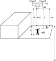
- FIG. 5 is a diagram for explaining a method of obtaining a distance from a photographing device to a shot object according to an embodiment of the disclosure.
- FIG. 6 is a diagram showing a relationship between a focus distance and time according to an embodiment of the disclosure.
- FIG. 7 is a diagram showing a relationship between a focus evaluation value and a focus distance according to an embodiment of the disclosure.
- FIG. 8 is a flowchart of a shooting process according to an embodiment of the disclosure.
- FIG. 9 is a diagram of a hardware configuration according to an embodiment of the disclosure.
- a block may represent a stage of a process of performing operations or a “unit” of a device that performs operations.
- the specific stage and “unit” can be implemented by programmable circuits and/or processors.
- a dedicated circuit may include a digital and/or an analog circuit, or may include an integrated circuit (IC) and/or a discrete circuit.
- a programmable circuit may include a reconfigurable circuit.
- the reconfigurable circuit may include a circuit with a logic operation such as logic AND, logic OR, logic XOR, logic NAND, logic NOR, or another logic operation, a flip-flop, a register, a field programmable gate array (FPGA), a programmable logic array (PLA), or another memory component.
- a logic operation such as logic AND, logic OR, logic XOR, logic NAND, logic NOR, or another logic operation, a flip-flop, a register, a field programmable gate array (FPGA), a programmable logic array (PLA), or another memory component.
- the computer-readable medium may include any tangible device that can store instructions to be executed by a suitable device.
- the computer-readable medium with instructions stored is provided with a product including instructions that can be executed to create means for performing operations specified by the flowchart or the block diagram.
- the computer-readable medium may include electronic storage media, magnetic storage media, optical storage media, electromagnetic storage media, semiconductor storage media, or the like.
- the computer-readable medium may include a floppy disk (registered trademark), a floppy disk, a hard disk, a random-access memory (RAM), a read-only memory (ROM), an erasable programmable read-only memory (EPROM or a flash memory), an electrically erasable programmable read-only memory (EEPROM), a static random access memory (SRAM), a compact disc read-only memory (CD-ROM), a digital versatile disc (DVD), a Blu-ray® disc, a memory stick, or an integrated circuit card, etc.
- a floppy disk registered trademark
- a floppy disk a floppy disk
- a hard disk a random-access memory (RAM)
- RAM random-access memory
- ROM read-only memory
- EPROM or a flash memory erasable programmable read-only memory
- EEPROM electrically erasable programmable read-only memory
- SRAM static random access memory
- CD-ROM compact disc read-only memory
- the computer-readable instructions may include any one of source code or object code described in any combination of one or more programming languages.
- the source code or object code can include a programming language such as assembly instructions, instruction set architecture (ISA) instructions, machine instructions, machine-related instructions, microcode, firmware instructions, status setting data, or object-oriented programming languages such as Smalltalk, JAVA (registered trademark), C++, etc., or “C” programming language or similar programming languages.
- the computer-readable instructions may be provided locally or via a wide area network (WAN) such as a local area network (LAN) or an internet to a processor or a programmable circuit of a general-purpose computer, a special-purpose computer, or other programmable data processing device.
- WAN wide area network
- LAN local area network
- the processor or programmable circuit can execute computer-readable instructions to create means for performing the operations specified in the flowchart or block diagram.
- Examples of processors include computer processors, processing units, microprocessors, digital signal processors, controllers, microcontrollers, and so on.
- FIG. 1 is a schematic diagram showing an unmanned aerial vehicle (UAV) 10 and a remote operation device 300 according to an embodiment of the disclosure.
- the UAV 10 includes a UAV body 20 , a gimbal 50 , a plurality of photographing devices 60 , and a photographing device 100 .
- the gimbal 50 and the photographing device 100 are an example of a photographing system.
- the UAV 10 is an example of a mobile object, while the latter can include an aerial object movable in the air, a vehicle movable on the ground, or a ship movable on water.
- the aerial object movable in the air can include not only UAV, but also other aircraft, airship, or helicopter that is movable in the air.
- the UAV body 20 includes a plurality of rotors.
- the plurality of rotors are an example of a propulsion unit.
- the UAV body 20 causes the UAV 10 to fly by controlling the rotation of the plurality of rotors.
- the UAV body 20 uses, for example, four rotors to fly the UAV 10 .
- the number of rotors is not limited to four. Further, the UAV 10 may also be a fixed-wing aircraft without rotors.
- the photographing device 100 may be an imaging camera that shoots an object included in a desired shooting range.
- the gimbal 50 rotatably supports the photographing device 100 .
- the gimbal 50 is an example of a support mechanism.
- the gimbal 50 may use an actuator to support the photographing device 100 rotatably around a pitch axis.
- the gimbal 50 may use actuators to further support the photographing device 100 rotatably around a roll axis and a yaw axis, respectively.
- the gimbal 50 can change an attitude of the photographing device 100 by rotating the photographing device 100 around at least one of the yaw axis, the pitch axis, or the roll axis.
- the plurality of photographing devices 60 may be sensing cameras that shoot surroundings of the UAV 10 in order to control the flight of the UAV 10 .
- the two photographing devices 60 may be provided at a nose, that is, the front of the UAV 10 .
- the other two photographing devices 60 may be provided at a bottom surface of the UAV 10 .
- the two photographing devices 60 on the front side may be paired to function as a stereo camera.
- the two photographing devices 60 on the bottom side may also be paired to function as a stereo camera.
- Three-dimensional spatial data around the UAV 10 can be generated from images shot by the plurality of photographing devices 60 .
- the number of photographing devices 60 included in the UAV 10 is not limited to four.
- the UAV 10 may include at least one photographing device 60 .
- the UAV 100 may include at least one photographing device 60 at each of the nose, a tail, a side surface, a bottom surface, and a top surface of the UAV 10 .
- An angle of view of the photographing device 60 may be greater than an angle of view of the photographing device 100 .
- the photographing device 60 may have a single focus lens or a fisheye lens.
- the remote operation device 300 communicates with the UAV 10 to remotely operate the UAV 10 .
- the remote operation device 300 can wirelessly communicate with the UAV 10 .
- the remote operation device 300 transmits to the UAV 10 instruction information indicating various instructions related to the movement of the UAV 10 such as ascending, descending, accelerating, decelerating, going forward, going backward, or rotating.
- the instruction information may include instruction information to raise a height of the UAV 10 .
- the instruction information may show the height at which the UAV 10 should be located.
- the UAV 10 moves to the height indicated by the instruction information received from the remote operation device 300 .
- the instruction information may include an ascending instruction to raise the UAV 10 .
- UAV 10 ascends while receiving the ascending instruction. When the height of the UAV 10 has reached an upper height limit, the UAV 10 can be prevented from ascending even if the ascending instruction is received.
- FIG. 2 shows functional blocks of the UAV 10 according to an embodiment of the disclosure.
- the UAV 10 includes a UAV controller 30 , a memory 37 , a communication interface 36 , a propulsion unit 40 , a GPS receiver 41 , an inertial measurement unit (IMU) 42 , a magnetic compass 43 , a barometric altimeter 44 , temperature sensor 45 , a humidity sensor 46 , a gimbal 50 , a photographing device 60 , and a photographing device 100 .
- IMU inertial measurement unit
- the communication interface 36 communicates with other devices such as the remote operation device 300 .
- the communication interface 36 may receive instruction information including various instructions to the UAV controller 30 from the remote operation device 300 .
- the memory 37 stores programs that the UAV controller 30 uses to control the propulsion unit 40 , the GPS receiver 41 , the IMU 42 , the magnetic compass 43 , the barometric altimeter 44 , the temperature sensor 45 , the humidity sensor 46 , the gimbal 50 , the photographing device 60 , and the photographing device 100 .
- the memory 37 may be a computer-readable recording medium, and may include at least one of an SRAM, a DRAM, an EPROM, an EEPROM, or a flash memory such as a USB memory or a solid-state drive (SSD).
- the memory 37 may be provided inside the UAV body 20 .
- the memory may be configured to be detachable from the UAV body 20 .
- the UAV controller 30 may control a flight and shooting of the UAV 10 in accordance with a program stored in the memory 37 .
- the UAV controller 30 may be constituted by a microprocessor such as a CPU or an MPU, a microcontroller such as an MCU, or the like.
- the UAV controller 30 may control the flight and shooting of the UAV 10 in accordance with instructions received from the remote operation device 300 via the communication interface 36 .
- the propulsion unit 40 propels the UAV 10 .
- the propulsion unit 40 includes a plurality of rotors and a plurality of drive motors that rotate the plurality of rotors.
- the propulsion unit 40 rotates the plurality of rotors via the plurality of drive motors according an instruction from the UAV controller 30 to cause the UAV 10 to fly.
- the GPS receiver 41 receives a plurality of signals indicating the time transmitted from a plurality of GPS satellites.
- the GPS receiver 41 calculates a position (latitude and longitude) of the GPS receiver 41 , that is, a position (latitude and longitude) of the UAV 10 based on the received plurality of signals.
- the IMU 42 detects an attitude of the UAV 10 .
- the IMU 42 detects accelerations in directions of three axes of front-back, left-right, and up-down, and angular velocities in directions of three axes of a pitch axis, a roll axis, and a yaw axis of the UAV 10 as the attitude of the UAV 10 .
- the magnetic compass 43 detects an orientation of a nose of the UAV 10 .
- the barometric altimeter 44 detects a flight height of the UAV 10 .
- the barometric altimeter 44 detects an air pressure around the UAV 10 and converts the detected air pressure to a height to detect the height.
- the temperature sensor 45 detects a temperature around the UAV 10 .
- the humidity sensor 46 detects a humidity around the UAV 10 .
- the photographing device 100 includes a photographing unit 102 and a lens unit 200 .
- the lens unit 200 is an embodiment of a lens device.
- the photographing unit 102 includes an image sensor 120 , an imaging controller 110 , and a memory 130 .
- the image sensor 120 may include CCD or CMOS.
- the image sensor 120 shoots optical images formed through a plurality of lenses 210 and outputs the shot images to the imaging controller 110 .
- the imaging controller 110 may be constituted by a microprocessor such as a CPU or an MPU, a microcontroller such as an MCU, or the like.
- the imaging controller 110 may control the photographing device 100 in accordance with an operation instruction of the photographing device 100 from the UAV controller 30 .
- the imaging controller 110 is an example of a first controller and a second controller.
- the memory 130 may be a computer-readable recording medium, and may include at least one of an SRAM, a DRAM, an EPROM, an EEPROM, or a flash memory such as a USB memory or an SSD.
- the memory 130 stores programs that the imaging controller 110 uses to control the image sensor 120 and the like.
- the memory 130 may be provided inside a housing of the photographing device 100 .
- the memory 130 may be configured to be detachable from the housing of the photographing device 100 .
- the lens unit 200 includes a plurality of lenses 210 , a plurality of lens drivers 212 , and a lens controller 220 .
- the plurality of lenses 210 may include zoom lenses, varifocal lenses, or focus lenses. At least a part of or the entire plurality of lenses 210 are configured to be movable along an optical axis.
- the lens unit 200 may be an interchangeable lens that is provided to be detachable from the photographing unit 102 .
- the lens driver 212 moves at least a part of or the entire plurality of lenses 210 along the optical axis through a mechanism member such as a cam ring.
- the lens driver 212 may include an actuator.
- the actuator may include a stepper motor.
- the lens controller 220 drives the lens driver 212 according to a lens control command from the photographing unit 102 , and moves at least one of the plurality of lenses 210 along the optical axis through a mechanism member.
- the lens control command may be a zoom control command or a focus control command.
- the lens unit 200 further includes a memory 222 and a position sensor 214 .
- the lens controller 220 controls the lens 210 via the lens driver 212 to move along the optical axis according to the lens operation command from the photographing unit 102 . Some or all of the plurality of lenses 210 move along the optical axis.
- the lens controller 220 performs at least one of a zoom action or a focus action by moving at least one of the lenses 210 along the optical axis.
- the position sensor 214 detects a position of the lens 210 .
- the position sensor 214 can detect a current zoom position or a current focus position.
- the lens driver 212 may include a shake correction mechanism.
- the lens controller 220 may move the lens 210 in a direction along the optical axis or a direction perpendicular to the optical axis via a shake correction mechanism to perform shake correction.
- the lens driver 212 may drive a shake correction mechanism by a stepper motor to perform shake correction.
- the shake correction mechanism may be driven by a stepper motor to move the image sensor 120 in a direction along the optical axis or a direction perpendicular to the optical axis to perform shake correction.
- the memory 222 stores control values of the plurality of lenses 210 moved via the lens driver 212 .
- the memory 222 may include at least one of an SRAM, a DRAM, an EPROM, an EEPROM, or a flash memory such as a USB memory.
- the photographing device 100 can efficiently determine a lens position of the focus lens focused on a desired object based on a focus evaluation value that evaluates a focus state such as an evaluation value of contrast.
- the photographing device 100 when the photographing device 100 performs a contrast autofocus, it derives the focus evaluation value while moving the focus lens from an infinity side to a closest side. Then, the photographing device 100 determines a lens position of the focus lens at which an extreme value of the focus evaluation value is obtained, as the lens position of the focus lens focused on the desired subject.
- the photographing device 100 shoots a person on the ground while the UAV 10 is flying. A height of the person can be determined to a certain extent. Therefore, if a height of the UAV 10 can be determined, a distance from the photographing device 100 to the person can be determined to a certain extent. That is, there is a high possibility that the lens position of the focus lens at which the extreme value of the focus evaluation value is obtained can be determined without the photographing device 100 moving the focus lens from the infinity side to the closest side.
- a range of the lens position of the focus lens that is a target for deriving the focus evaluation value is limited.
- the “shot object” refers to an object being shot, and is also referred to as a “target object.”
- the photographing device 100 moves the focus lens, more images are shot near the determined lens position of the focus lens than at positions except the determined lens position of the focus lens.
- the photographing device 100 shoots moving images while moving the focus lens. Further, while moving the focus lens, the photographing device 100 shoots more images near the determined lens position of the focus lens than at other positions except the determined lens position of the focus lens.
- the photographing device 100 can generate a still image by allowing a user to select an image focused on a desired object from the shot moving images.
- the photographing device 100 shoots more images near the focus position at which the focus evaluation value is relatively high. Therefore, the photographing device 100 can more reliably shoot an image focusing on the desired object.
- the imaging controller 110 includes an obtaining circuit 112 , a range determination circuit 114 , a derivation circuit 116 , and a distance determination circuit 118 .
- the obtaining circuit 112 obtains the height of the photographing device 100 .
- the obtaining circuit 112 may obtain the height of the UAV 10 measured by the barometric altimeter 44 and use it as the height of the photographing device 100 .
- the range determination circuit 114 determines a first range of the focus distance of the photographing device 100 from which the focus evaluation value should be derived.
- the focus distance is a distance from the photographing device 100 to an object in a focus state.
- the focus state is, for example, a state in which the focus evaluation value is greater than or equal to a preset value in an image shot by the photographing device 100 .
- the range determination circuit 114 may determine a range from infinity to a first distance as the first range of the focus distance.
- the first distance may be a distance obtained by subtracting a preset amount from a distance from the photographing device 100 to the ground or the sea. The distance from the photographing device 100 to the ground or the sea may correspond to the height of the photographing device 100 .
- the range determination circuit 114 may determine a range from infinity to a certain distance as the first range of the focus distance. The certain distance is closer to the photographing device 100 by a preset amount than the distance from the photographing device 100 to the ground or the sea corresponding to the height of the photographing device 100 .
- the range determination circuit 114 may determine the first range of the focus distance to be a range to a preset distance that is closer to the photographing device 100 by a preset amount.
- the ground can also be defined as a floor of a certain building. The height can be determined based on the floor.
- the obtaining circuit 112 may obtain a distance from the photographing device 100 to the shot object.
- the distance from the photographing device 100 to the shot object and the height of the photographing device 100 described above are both referred to as a “reference distance.”
- the obtaining circuit 112 may obtain a distance between the shot object and a measurement device, e.g., a ranging sensor such as an infrared sensor or an ultrasonic sensor, a stereo camera, etc., as the distance from the photographing device 100 to the shot object.
- the range determination circuit 114 may determine the first range of the focus distance of the photographing device 100 from which the focus evaluation value should be derived based on the distance from the photographing device 100 to the shot object.
- the range determination circuit 114 may determine a range from infinity to a certain distance as the first range of the focus distance. The certain distance is closer to the photographing device 100 by a preset amount than the distance from the photographing device 100 to the shot object.
- the range determination circuit 114 may determine a range from infinity to a distance H-a as the first range of the focus distance, and the distance H-a is closer to the photographing device 100 by a preset amount a than the distance from the photographing device 100 to the ground corresponding to the height of the photographing device 100 .
- the range determination circuit 114 may determine a range from infinity to a distance L-b as the first range of the focus distance.
- the distance L-b is closer to the photographing device 100 by a preset amount b than the distance L from the photographing device 100 to the shot object.
- the preset amount can be set in advance according to the type of the shot object.
- the preset amount can be set in advance according to a size of the shot object.
- the preset amount can be set in advance according to a product of a height of the shot object and a preset ratio.
- the imaging controller 110 causes the photographing device 100 to shoot a plurality of images while changing the focus distance within the first range of the focus distance. That is, the imaging controller 110 causes the photographing device 100 to shoot a plurality of images while changing the lens position of the focus lens within the first range of the focus distance.
- the derivation circuit 116 derives the focus evaluation values for various focus distances based on the plurality of shot images.
- the derivation circuit 116 derives the focus evaluation values for various lens positions within a lens position range of the focus lens corresponding to the first range based on the plurality of shot images.
- the distance determination circuit 118 determines a first focus distance of the photographing device that should cause the photographing device 100 to shoot an image based on the focus evaluation value derived by the derivation circuit 116 .
- the first focus distance is also referred to as an “in-focus distance.”
- the distance determination circuit 118 determines a lens position of the focus lens at which a focus evaluation value as an extreme value among the various focus evaluation values derived by the derivation circuit 116 is obtained, and determines a focus distance corresponding to the lens position as the first focus distance.
- a movement range of the focus lens for which a focus evaluation value should be derived is limited to a range based on the height of the photographing device 100 or the distance to the shot object.
- the imaging controller 110 can cause the photographing device 100 to shoot a plurality of images while changing the focus distance of the photographing device 100 within a second range of the focus distance including the first focus distance.
- the imaging controller 110 can cause the photographing device 100 to shoot a plurality of images while moving the focus lens within a lens position range including the lens position of the focus lens corresponding to the first focus distance.
- the imaging controller 110 can cause the photographing device to shoot more images per unit distance range within the second range of the focus distance including the first focus distance than outside the second range.
- the imaging controller 110 can cause the photographing device 100 to shoot moving images at a higher frame rate within the second range of the focus distance including the first focus distance than outside the second range.
- the photographing device 100 can generate a still image 510 by allowing a user to select an image focused on the desired shot object among the plurality of shot images 500 while changing the focus distance of the photographing device 100 within the second range of the focus distance including the first focus distance.
- the remote operation device 300 can determine a current position of the remote operation device 300 .
- the UAV 10 may also have a GPS function. Therefore, the obtaining circuit 112 may calculate a distance K based on the current position (latitude and longitude) of the remote operation device 300 and the current position (latitude and longitude) of the UAV 10 . Further, the obtaining circuit 112 may calculate a distance L from the photographing device 100 to the user 400 based on a current height H and the distance K of the UAV 10 .
- the obtaining circuit 112 can obtain a distance from the photographing device 100 to the object. Further, there is a tracking mode as an operation mode of the UAV 10 . In the tracking mode, the UAV 10 flies in a manner to maintain a preset distance from the remote operation device 300 . When the UAV 10 is operating in the tracking mode, the obtaining circuit 112 may obtain a distance set in the tracking mode as the distance from the photographing 100 to the shot object.
- FIG. 6 shows a relationship between the focus distance and time according to an embodiment.
- the range determination circuit 114 determines the first range of the focus distance of the photographing device 100 from which the focus evaluation value should be derived. Then, from time T 0 to time T 1 , the imaging controller 110 moves the focus lens. The focal length is changed in the first range. In this way, when the focus lens is moved, the derivation circuit 116 derives the focus evaluation position. Further, as shown in FIG. 7 , the distance determination circuit 118 determines a focus distance f 1 at which an extreme value 600 of the focus evaluation value is obtained. Then, the imaging controller 110 returns the lens position of the focus lens to a position corresponding to infinity.
- the imaging controller 110 causes the photographing device 100 to shoot moving images while moving the lens position of the focus lens from time T 2 to time T 3 .
- the imaging controller 110 suspends the movement of the focus lens at the lens position corresponding to the focus distance f 1 at which the extreme value of the focus evaluation value is obtained, and causes the photographing device 100 to shoot more images at the lens position. Further, when the imaging controller 110 causes the photographing device 100 to shoot moving images, it is not necessary to move the focus lens from infinity to the closest side, but only to move the focus lens from infinity to a lens position corresponding to a focal length closer to the photographing device 100 by a preset amount from the focus distance f 1 .
- FIG. 8 is a flowchart of a shooting process performed by the photographing device 100 mounted at the UAV 10 according to an embodiment of the disclosure.
- the obtaining circuit 112 obtains the height of the UAV 10 .
- the obtaining circuit 112 may obtain the height of the UAV 10 measured by the barometric altimeter 44 via the UAV controller 30 . Instead of the height, the obtaining circuit 112 may obtain the distance from the photographing device 100 to the shot object.
- the range determination circuit 114 determines a scanning range of the focus lens for which the focus evaluation value should be derived based on the height or the distance to the shot object (S 104 ).
- the derivation circuit 116 derives the focus evaluation value.
- the distance determination circuit 118 determines a focus distance at which the photographing device 100 should perform shooting by determining the lens position of the focus lens at which the extreme value of the focus evaluation value is obtained.
- the imaging controller 110 causes the photographing device 100 to shoot moving images while moving the focus lens from infinity to the closest side, so that more images can be obtained than at lens positions except the determined lens position.
- the imaging controller 110 stores the shot moving images in the memory 130 .
- the photographing device 100 moves the focus lens, more images are shot near the determined lens position of the focus lens than at positions except the determined lens position of the focus lens.
- the photographing device 100 can generate a still image by allowing a user to select an image focused on the desired object from the shot moving images.
- the photographing device 100 shoots more images near the focus position at which the focus evaluation value is relatively high. Therefore, the photographing device 100 can more reliably shoot the image focusing on the desired object.
- FIG. 9 shows an example of a computer 1200 that may fully or partially embody the present disclosure.
- the program installed on the computer 1200 can make the computer 1200 function as an operation associated with a device according to the embodiments of the present disclosure or one or more “units” of the device.
- the program can cause the computer 1200 to perform the operation or the one or more “units.”
- the program enables the computer 1200 to execute a process or stages of the process consistent with embodiments of the present disclosure.
- the program can be executed by a CPU 1212 to make the computer 1200 execute specific operations associated with some or all of the blocks in the flowcharts or block diagrams described in this disclosure.
- the computer 1200 of this disclosure includes the CPU 1212 and a RAM 1214 , which are connected to each other through a host controller 1210 .
- the computer 1200 further includes a communication interface 1222 , an input/output unit, which is connected to the host controller 1210 through an input/output controller 1220 .
- the computer 1200 also includes a ROM 1230 .
- the CPU 1212 operates in accordance with programs stored in the ROM 1230 and RAM 1214 to control each unit.
- the communication interface 1222 communicates with other electronic devices through a network.
- a hard disk drive can store programs and data used by the CPU 1212 of the computer 1200 .
- the ROM 1230 stores a bootloader executed by the computer 1200 during operation, and/or a program dependent on the hardware of the computer 1200 .
- the program is provided through a computer-readable medium such as a CR-ROM, a USB memory, or an IC card, or a network.
- the program is installed in the RAM 1214 or the ROM 1230 , which are examples of computer-readable medium, and is executed by the CPU 1212 .
- the information processing described in the programs is read by the computer 1200 and causes cooperation between the program and the various types of hardware resources described above.
- the device or method may be constituted by realizing the operation or processing of information with the use of the computer 1200 .
- the CPU 1212 can execute a communication program loaded in the RAM 1214 , and based on the processing described in the communication program, instruct the communication interface 1222 to perform communication processing.
- the communication interface 1222 reads transmission data stored in a transmission buffer provided in a recording medium such as the RAM 1214 or a USB memory, and transmits the read transmission data to a network or writes received data received from the network in a receiving buffer provided in a recording medium.
- the CPU 1212 can execute various types of operations, information processing, conditional determination, conditional transfer, unconditional transfer, or information retrieval/replacement specified by the instruction sequence of the program described in the disclosure, and write the result back to the RAM 1214 .
- the CPU 1212 can retrieve information in files, databases, or the like in the recording medium.
- the CPU 1212 may retrieve an entry that matches the condition that specifies the attribute value of the first attribute from the plurality of entries and read the attribute value of the second attribute stored in the entry to obtain the attribute value of the second attribute associated with the first attribute meeting a preset condition.
- the programs or software modules described above may be stored at the computer 1200 or at a computer-readable storage medium near the computer 1200 .
- a recording medium such as a hard disk or a RAM provided in a server system connected to a dedicated communication network or the internet can be used as a computer-readable storage medium to provide the program to the computer 1200 through the network.
Landscapes
- Engineering & Computer Science (AREA)
- Physics & Mathematics (AREA)
- Multimedia (AREA)
- Signal Processing (AREA)
- General Physics & Mathematics (AREA)
- Optics & Photonics (AREA)
- Computing Systems (AREA)
- Computer Vision & Pattern Recognition (AREA)
- Theoretical Computer Science (AREA)
- Studio Devices (AREA)
- Aviation & Aerospace Engineering (AREA)
- Accessories Of Cameras (AREA)
- Automatic Focus Adjustment (AREA)
Abstract
Description
- Patent Document 1: International Application Publication No. WO2017/006538.
Claims (18)
Applications Claiming Priority (4)
| Application Number | Priority Date | Filing Date | Title |
|---|---|---|---|
| JP2018098295A JP6668570B2 (en) | 2018-05-22 | 2018-05-22 | Control device, imaging device, moving object, control method, and program |
| JPJP2018-098295 | 2018-05-22 | ||
| JP2018-098295 | 2018-05-22 | ||
| PCT/CN2019/087404 WO2019223614A1 (en) | 2018-05-22 | 2019-05-17 | Control apparatus, photographing apparatus, moving body, control method, and program |
Related Parent Applications (1)
| Application Number | Title | Priority Date | Filing Date |
|---|---|---|---|
| PCT/CN2019/087404 Continuation WO2019223614A1 (en) | 2018-05-22 | 2019-05-17 | Control apparatus, photographing apparatus, moving body, control method, and program |
Publications (2)
| Publication Number | Publication Date |
|---|---|
| US20210075973A1 US20210075973A1 (en) | 2021-03-11 |
| US11265456B2 true US11265456B2 (en) | 2022-03-01 |
Family
ID=68616219
Family Applications (1)
| Application Number | Title | Priority Date | Filing Date |
|---|---|---|---|
| US17/086,056 Expired - Fee Related US11265456B2 (en) | 2018-05-22 | 2020-10-30 | Control device, photographing device, mobile object, control method, and program for image acquisition |
Country Status (4)
| Country | Link |
|---|---|
| US (1) | US11265456B2 (en) |
| JP (1) | JP6668570B2 (en) |
| CN (1) | CN110785997B (en) |
| WO (1) | WO2019223614A1 (en) |
Families Citing this family (2)
| Publication number | Priority date | Publication date | Assignee | Title |
|---|---|---|---|---|
| US20210231801A1 (en) * | 2020-01-28 | 2021-07-29 | ProTek Technologies, Inc. | Monitoring device for use with an alert management process |
| CN113438414B (en) * | 2021-06-11 | 2022-10-11 | 深圳市道通智能航空技术股份有限公司 | Focusing method, focusing device and unmanned aerial vehicle |
Citations (21)
| Publication number | Priority date | Publication date | Assignee | Title |
|---|---|---|---|---|
| CN1497320A (en) | 2002-10-09 | 2004-05-19 | ������������ʽ���� | Photographic equipment, photographic method and program for realizing photographic method and its storage medium |
| CN1716078A (en) | 2004-06-03 | 2006-01-04 | 佳能株式会社 | Image pickup apparatus and image pickup method |
| CN1856021A (en) | 2005-04-21 | 2006-11-01 | 佳能株式会社 | Image-taking apparatus and focusing method |
| JP2006317593A (en) | 2005-05-11 | 2006-11-24 | Fuji Photo Film Co Ltd | Imaging device |
| CN101494735A (en) | 2008-01-25 | 2009-07-29 | 索尼株式会社 | Imaging apparatus, imaging apparatus control method, and computer program |
| CN101493567A (en) | 2008-01-25 | 2009-07-29 | 索尼株式会社 | Imaging apparatus, imaging apparatus control method, and computer program |
| US20090190023A1 (en) * | 2008-01-25 | 2009-07-30 | Sony Corporation | Imaging apparatus, imaging apparatus control method, and computer program |
| CN101742107A (en) | 2008-11-25 | 2010-06-16 | 索尼株式会社 | Imaging device and imaging method |
| CN102348058A (en) | 2010-07-27 | 2012-02-08 | 三洋电机株式会社 | Electronic equipment |
| US20120154670A1 (en) | 2010-12-21 | 2012-06-21 | Samsung Electronics Co., Ltd. | Photographing Apparatus and Method to Reduce Auto-Focus Time |
| US20140176783A1 (en) | 2012-12-21 | 2014-06-26 | Canon Kabushiki Kaisha | Image capturing apparatus and method for controlling the same |
| CN104038689A (en) | 2013-03-05 | 2014-09-10 | 奥林巴斯映像株式会社 | Image processing device and image processing method |
| CN106254754A (en) | 2015-06-08 | 2016-12-21 | 奥林巴斯株式会社 | Filming apparatus, image processing apparatus, the control method of filming apparatus |
| WO2017006538A1 (en) | 2015-07-07 | 2017-01-12 | パナソニックIpマネジメント株式会社 | Image capturing device and still image generating method |
| JP2017062529A (en) | 2015-09-24 | 2017-03-30 | キヤノン株式会社 | Direction control method |
| WO2017090233A1 (en) | 2015-11-24 | 2017-06-01 | パナソニックIpマネジメント株式会社 | Imaging device |
| CN106998424A (en) | 2016-01-23 | 2017-08-01 | 奥林巴斯株式会社 | Camera device and image capture method |
| CN107079102A (en) | 2016-09-26 | 2017-08-18 | 深圳市大疆创新科技有限公司 | Focusing method, camera and drone |
| CN207191469U (en) | 2017-09-21 | 2018-04-06 | 黄仁杰 | A kind of UAS for ranging of taking photo by plane |
| US20180204331A1 (en) * | 2016-07-21 | 2018-07-19 | Gopro, Inc. | Subject tracking systems for a movable imaging system |
| JP2019032370A (en) | 2017-08-04 | 2019-02-28 | キヤノン株式会社 | Imaging apparatus and control method thereof |
-
2018
- 2018-05-22 JP JP2018098295A patent/JP6668570B2/en not_active Expired - Fee Related
-
2019
- 2019-05-17 WO PCT/CN2019/087404 patent/WO2019223614A1/en not_active Ceased
- 2019-05-17 CN CN201980003162.1A patent/CN110785997B/en not_active Expired - Fee Related
-
2020
- 2020-10-30 US US17/086,056 patent/US11265456B2/en not_active Expired - Fee Related
Patent Citations (22)
| Publication number | Priority date | Publication date | Assignee | Title |
|---|---|---|---|---|
| CN1497320A (en) | 2002-10-09 | 2004-05-19 | ������������ʽ���� | Photographic equipment, photographic method and program for realizing photographic method and its storage medium |
| CN1716078A (en) | 2004-06-03 | 2006-01-04 | 佳能株式会社 | Image pickup apparatus and image pickup method |
| US20100201864A1 (en) | 2004-06-03 | 2010-08-12 | Canon Kabushiki Kaisha | Image pickup apparatus and image pickup method |
| CN1856021A (en) | 2005-04-21 | 2006-11-01 | 佳能株式会社 | Image-taking apparatus and focusing method |
| JP2006317593A (en) | 2005-05-11 | 2006-11-24 | Fuji Photo Film Co Ltd | Imaging device |
| CN101494735A (en) | 2008-01-25 | 2009-07-29 | 索尼株式会社 | Imaging apparatus, imaging apparatus control method, and computer program |
| CN101493567A (en) | 2008-01-25 | 2009-07-29 | 索尼株式会社 | Imaging apparatus, imaging apparatus control method, and computer program |
| US20090190023A1 (en) * | 2008-01-25 | 2009-07-30 | Sony Corporation | Imaging apparatus, imaging apparatus control method, and computer program |
| CN101742107A (en) | 2008-11-25 | 2010-06-16 | 索尼株式会社 | Imaging device and imaging method |
| CN102348058A (en) | 2010-07-27 | 2012-02-08 | 三洋电机株式会社 | Electronic equipment |
| US20120154670A1 (en) | 2010-12-21 | 2012-06-21 | Samsung Electronics Co., Ltd. | Photographing Apparatus and Method to Reduce Auto-Focus Time |
| US20140176783A1 (en) | 2012-12-21 | 2014-06-26 | Canon Kabushiki Kaisha | Image capturing apparatus and method for controlling the same |
| CN104038689A (en) | 2013-03-05 | 2014-09-10 | 奥林巴斯映像株式会社 | Image processing device and image processing method |
| CN106254754A (en) | 2015-06-08 | 2016-12-21 | 奥林巴斯株式会社 | Filming apparatus, image processing apparatus, the control method of filming apparatus |
| WO2017006538A1 (en) | 2015-07-07 | 2017-01-12 | パナソニックIpマネジメント株式会社 | Image capturing device and still image generating method |
| JP2017062529A (en) | 2015-09-24 | 2017-03-30 | キヤノン株式会社 | Direction control method |
| WO2017090233A1 (en) | 2015-11-24 | 2017-06-01 | パナソニックIpマネジメント株式会社 | Imaging device |
| CN106998424A (en) | 2016-01-23 | 2017-08-01 | 奥林巴斯株式会社 | Camera device and image capture method |
| US20180204331A1 (en) * | 2016-07-21 | 2018-07-19 | Gopro, Inc. | Subject tracking systems for a movable imaging system |
| CN107079102A (en) | 2016-09-26 | 2017-08-18 | 深圳市大疆创新科技有限公司 | Focusing method, camera and drone |
| JP2019032370A (en) | 2017-08-04 | 2019-02-28 | キヤノン株式会社 | Imaging apparatus and control method thereof |
| CN207191469U (en) | 2017-09-21 | 2018-04-06 | 黄仁杰 | A kind of UAS for ranging of taking photo by plane |
Non-Patent Citations (1)
| Title |
|---|
| The World Intellectual Property Organization (WIPO) International Search Report for PCT/CN2019/087404 dated Aug. 20, 2019 4 Pages (including translation). |
Also Published As
| Publication number | Publication date |
|---|---|
| JP2019205047A (en) | 2019-11-28 |
| WO2019223614A1 (en) | 2019-11-28 |
| US20210075973A1 (en) | 2021-03-11 |
| JP6668570B2 (en) | 2020-03-18 |
| CN110785997B (en) | 2021-11-05 |
| CN110785997A (en) | 2020-02-11 |
Similar Documents
| Publication | Publication Date | Title |
|---|---|---|
| US20210120171A1 (en) | Determination device, movable body, determination method, and program | |
| US10942331B2 (en) | Control apparatus, lens apparatus, photographic apparatus, flying body, and control method | |
| CN111356954B (en) | Control device, moving body, control method, and program | |
| US20210014427A1 (en) | Control device, imaging device, mobile object, control method and program | |
| US20200092455A1 (en) | Control device, photographing device, photographing system, and movable object | |
| US20200304719A1 (en) | Control device, system, control method, and program | |
| US11265456B2 (en) | Control device, photographing device, mobile object, control method, and program for image acquisition | |
| CN109844634B (en) | Control device, camera device, flying body, control method, and program | |
| US11066182B2 (en) | Control apparatus, camera apparatus, flying object, control method and program | |
| US20200410219A1 (en) | Moving object detection device, control device, movable body, moving object detection method and program | |
| US20210105411A1 (en) | Determination device, photographing system, movable body, composite system, determination method, and program | |
| CN111226170A (en) | Control device, moving body, control method, and program | |
| US11363195B2 (en) | Control device, imaging device, imaging system, movable object, control method, and program | |
| US20210218879A1 (en) | Control device, imaging apparatus, mobile object, control method and program | |
| US20200241570A1 (en) | Control device, camera device, flight body, control method and program | |
| CN111357271B (en) | Control device, moving body, and control method | |
| JP7003357B2 (en) | Control device, image pickup device, moving object, control method, and program | |
| JP6878738B1 (en) | Control devices, imaging systems, moving objects, control methods, and programs | |
| JP6569157B1 (en) | Control device, imaging device, moving object, control method, and program | |
| CN112166374A (en) | Control device, imaging device, moving body, control method, and program | |
| JP2020052220A (en) | Controller, imaging device, mobile body, method for control, and program |
Legal Events
| Date | Code | Title | Description |
|---|---|---|---|
| AS | Assignment |
Owner name: SZ DJI TECHNOLOGY CO., LTD., CHINA Free format text: ASSIGNMENT OF ASSIGNORS INTEREST;ASSIGNOR:HONJO, KENICHI;REEL/FRAME:054269/0097 Effective date: 20201026 |
|
| FEPP | Fee payment procedure |
Free format text: ENTITY STATUS SET TO UNDISCOUNTED (ORIGINAL EVENT CODE: BIG.); ENTITY STATUS OF PATENT OWNER: LARGE ENTITY |
|
| STPP | Information on status: patent application and granting procedure in general |
Free format text: DOCKETED NEW CASE - READY FOR EXAMINATION |
|
| STPP | Information on status: patent application and granting procedure in general |
Free format text: NON FINAL ACTION MAILED |
|
| STPP | Information on status: patent application and granting procedure in general |
Free format text: RESPONSE TO NON-FINAL OFFICE ACTION ENTERED AND FORWARDED TO EXAMINER |
|
| STPP | Information on status: patent application and granting procedure in general |
Free format text: NOTICE OF ALLOWANCE MAILED -- APPLICATION RECEIVED IN OFFICE OF PUBLICATIONS |
|
| STCF | Information on status: patent grant |
Free format text: PATENTED CASE |
|
| FEPP | Fee payment procedure |
Free format text: MAINTENANCE FEE REMINDER MAILED (ORIGINAL EVENT CODE: REM.); ENTITY STATUS OF PATENT OWNER: LARGE ENTITY |
|
| LAPS | Lapse for failure to pay maintenance fees |
Free format text: PATENT EXPIRED FOR FAILURE TO PAY MAINTENANCE FEES (ORIGINAL EVENT CODE: EXP.); ENTITY STATUS OF PATENT OWNER: LARGE ENTITY |
|
| STCH | Information on status: patent discontinuation |
Free format text: PATENT EXPIRED DUE TO NONPAYMENT OF MAINTENANCE FEES UNDER 37 CFR 1.362 |