US11264573B2 - Organic electroluminescence device and amine compound for organic electroluminescence device - Google Patents
Organic electroluminescence device and amine compound for organic electroluminescence device Download PDFInfo
- Publication number
- US11264573B2 US11264573B2 US16/454,465 US201916454465A US11264573B2 US 11264573 B2 US11264573 B2 US 11264573B2 US 201916454465 A US201916454465 A US 201916454465A US 11264573 B2 US11264573 B2 US 11264573B2
- Authority
- US
- United States
- Prior art keywords
- group
- substituted
- unsubstituted
- carbon atoms
- ring carbon
- Prior art date
- Legal status (The legal status is an assumption and is not a legal conclusion. Google has not performed a legal analysis and makes no representation as to the accuracy of the status listed.)
- Active, expires
Links
- -1 amine compound Chemical class 0.000 title claims abstract description 125
- 238000005401 electroluminescence Methods 0.000 title claims abstract description 55
- 239000012044 organic layer Substances 0.000 claims abstract description 100
- 239000010410 layer Substances 0.000 claims description 166
- 150000001875 compounds Chemical class 0.000 claims description 99
- 230000005525 hole transport Effects 0.000 claims description 64
- 125000004432 carbon atom Chemical group C* 0.000 claims description 63
- 125000003118 aryl group Chemical group 0.000 claims description 35
- 125000001072 heteroaryl group Chemical group 0.000 claims description 34
- 125000001997 phenyl group Chemical group [H]C1=C([H])C([H])=C(*)C([H])=C1[H] 0.000 claims description 27
- 125000000217 alkyl group Chemical group 0.000 claims description 21
- 125000001424 substituent group Chemical group 0.000 claims description 21
- 125000006267 biphenyl group Chemical group 0.000 claims description 15
- TXCDCPKCNAJMEE-UHFFFAOYSA-N dibenzofuran Chemical group C1=CC=C2C3=CC=CC=C3OC2=C1 TXCDCPKCNAJMEE-UHFFFAOYSA-N 0.000 claims description 14
- 125000001624 naphthyl group Chemical group 0.000 claims description 13
- IYYZUPMFVPLQIF-ALWQSETLSA-N dibenzothiophene Chemical group C1=CC=CC=2[34S]C3=C(C=21)C=CC=C3 IYYZUPMFVPLQIF-ALWQSETLSA-N 0.000 claims description 12
- 125000004431 deuterium atom Chemical group 0.000 claims description 11
- 229910052805 deuterium Inorganic materials 0.000 claims description 10
- 125000000732 arylene group Chemical group 0.000 claims description 9
- 125000004435 hydrogen atom Chemical group [H]* 0.000 claims description 9
- 125000000113 cyclohexyl group Chemical group [H]C1([H])C([H])([H])C([H])([H])C([H])(*)C([H])([H])C1([H])[H] 0.000 claims description 6
- 229910052731 fluorine Inorganic materials 0.000 claims description 6
- 125000005549 heteroarylene group Chemical group 0.000 claims description 6
- 125000005561 phenanthryl group Chemical group 0.000 claims description 6
- 125000005580 triphenylene group Chemical group 0.000 claims description 6
- YJTKZCDBKVTVBY-UHFFFAOYSA-N 1,3-Diphenylbenzene Chemical group C1=CC=CC=C1C1=CC=CC(C=2C=CC=CC=2)=C1 YJTKZCDBKVTVBY-UHFFFAOYSA-N 0.000 claims description 5
- 125000005073 adamantyl group Chemical group C12(CC3CC(CC(C1)C3)C2)* 0.000 claims description 5
- 125000001153 fluoro group Chemical group F* 0.000 claims description 5
- 229910052760 oxygen Inorganic materials 0.000 claims description 5
- 229910052717 sulfur Inorganic materials 0.000 claims description 5
- 125000005567 fluorenylene group Chemical group 0.000 claims description 4
- 125000004957 naphthylene group Chemical group 0.000 claims description 4
- 125000000951 phenoxy group Chemical group [H]C1=C([H])C([H])=C(O*)C([H])=C1[H] 0.000 claims description 4
- 125000000843 phenylene group Chemical group C1(=C(C=CC=C1)*)* 0.000 claims description 4
- 125000005562 phenanthrylene group Chemical group 0.000 claims description 3
- 125000000609 carbazolyl group Chemical group C1(=CC=CC=2C3=CC=CC=C3NC12)* 0.000 claims 4
- YXFVVABEGXRONW-UHFFFAOYSA-N Toluene Chemical compound CC1=CC=CC=C1 YXFVVABEGXRONW-UHFFFAOYSA-N 0.000 description 228
- CSNNHWWHGAXBCP-UHFFFAOYSA-L Magnesium sulfate Chemical compound [Mg+2].[O-][S+2]([O-])([O-])[O-] CSNNHWWHGAXBCP-UHFFFAOYSA-L 0.000 description 124
- 239000000243 solution Substances 0.000 description 111
- VLKZOEOYAKHREP-UHFFFAOYSA-N n-Hexane Chemical compound CCCCCC VLKZOEOYAKHREP-UHFFFAOYSA-N 0.000 description 105
- XKRFYHLGVUSROY-UHFFFAOYSA-N Argon Chemical compound [Ar] XKRFYHLGVUSROY-UHFFFAOYSA-N 0.000 description 70
- 229910052943 magnesium sulfate Inorganic materials 0.000 description 62
- 239000000203 mixture Substances 0.000 description 51
- 238000006243 chemical reaction Methods 0.000 description 48
- 230000015572 biosynthetic process Effects 0.000 description 46
- 238000003786 synthesis reaction Methods 0.000 description 46
- 239000012043 crude product Substances 0.000 description 41
- BWHMMNNQKKPAPP-UHFFFAOYSA-L potassium carbonate Chemical compound [K+].[K+].[O-]C([O-])=O BWHMMNNQKKPAPP-UHFFFAOYSA-L 0.000 description 40
- 239000000463 material Substances 0.000 description 39
- 238000004992 fast atom bombardment mass spectroscopy Methods 0.000 description 36
- 229910052786 argon Inorganic materials 0.000 description 35
- 238000010898 silica gel chromatography Methods 0.000 description 35
- 239000002904 solvent Substances 0.000 description 35
- 238000003756 stirring Methods 0.000 description 35
- 230000000052 comparative effect Effects 0.000 description 32
- 238000001816 cooling Methods 0.000 description 31
- 238000001914 filtration Methods 0.000 description 31
- 238000010438 heat treatment Methods 0.000 description 31
- 238000002347 injection Methods 0.000 description 31
- 239000007924 injection Substances 0.000 description 31
- HPALAKNZSZLMCH-UHFFFAOYSA-M sodium;chloride;hydrate Chemical class O.[Na+].[Cl-] HPALAKNZSZLMCH-UHFFFAOYSA-M 0.000 description 31
- XLYOFNOQVPJJNP-UHFFFAOYSA-N water Substances O XLYOFNOQVPJJNP-UHFFFAOYSA-N 0.000 description 31
- 0 C*N([Ar])[Ar].CC.CC.[1*]C1=C2CC3=C(C=CC=C3)N2C2=C1C=CC=C2.[Ar] Chemical compound C*N([Ar])[Ar].CC.CC.[1*]C1=C2CC3=C(C=CC=C3)N2C2=C1C=CC=C2.[Ar] 0.000 description 27
- LFQSCWFLJHTTHZ-UHFFFAOYSA-N Ethanol Chemical compound CCO LFQSCWFLJHTTHZ-UHFFFAOYSA-N 0.000 description 20
- 229910000027 potassium carbonate Inorganic materials 0.000 description 20
- 238000000034 method Methods 0.000 description 17
- 230000000903 blocking effect Effects 0.000 description 12
- 239000002356 single layer Substances 0.000 description 12
- XEKOWRVHYACXOJ-UHFFFAOYSA-N Ethyl acetate Chemical compound CCOC(C)=O XEKOWRVHYACXOJ-UHFFFAOYSA-N 0.000 description 10
- FXHOOIRPVKKKFG-UHFFFAOYSA-N N,N-Dimethylacetamide Chemical compound CN(C)C(C)=O FXHOOIRPVKKKFG-UHFFFAOYSA-N 0.000 description 10
- NFHFRUOZVGFOOS-UHFFFAOYSA-N Pd(PPh3)4 Substances [Pd].C1=CC=CC=C1P(C=1C=CC=CC=1)C1=CC=CC=C1.C1=CC=CC=C1P(C=1C=CC=CC=1)C1=CC=CC=C1.C1=CC=CC=C1P(C=1C=CC=CC=1)C1=CC=CC=C1.C1=CC=CC=C1P(C=1C=CC=CC=1)C1=CC=CC=C1 NFHFRUOZVGFOOS-UHFFFAOYSA-N 0.000 description 10
- 238000000605 extraction Methods 0.000 description 10
- 229910052757 nitrogen Inorganic materials 0.000 description 10
- MFRIHAYPQRLWNB-UHFFFAOYSA-N sodium tert-butoxide Chemical compound [Na+].CC(C)(C)[O-] MFRIHAYPQRLWNB-UHFFFAOYSA-N 0.000 description 10
- BWHDROKFUHTORW-UHFFFAOYSA-N tritert-butylphosphane Chemical compound CC(C)(C)P(C(C)(C)C)C(C)(C)C BWHDROKFUHTORW-UHFFFAOYSA-N 0.000 description 10
- 150000001412 amines Chemical class 0.000 description 9
- 239000012267 brine Substances 0.000 description 9
- 150000002430 hydrocarbons Chemical group 0.000 description 9
- 229910052751 metal Inorganic materials 0.000 description 9
- 239000002184 metal Substances 0.000 description 9
- XLOMVQKBTHCTTD-UHFFFAOYSA-N Zinc monoxide Chemical compound [Zn]=O XLOMVQKBTHCTTD-UHFFFAOYSA-N 0.000 description 7
- 125000003277 amino group Chemical group 0.000 description 7
- 239000000872 buffer Substances 0.000 description 7
- SFHYNDMGZXWXBU-LIMNOBDPSA-N 6-amino-2-[[(e)-(3-formylphenyl)methylideneamino]carbamoylamino]-1,3-dioxobenzo[de]isoquinoline-5,8-disulfonic acid Chemical compound O=C1C(C2=3)=CC(S(O)(=O)=O)=CC=3C(N)=C(S(O)(=O)=O)C=C2C(=O)N1NC(=O)N\N=C\C1=CC=CC(C=O)=C1 SFHYNDMGZXWXBU-LIMNOBDPSA-N 0.000 description 6
- 229910052782 aluminium Inorganic materials 0.000 description 6
- 229920000767 polyaniline Polymers 0.000 description 6
- ATTVYRDSOVWELU-UHFFFAOYSA-N 1-diphenylphosphoryl-2-(2-diphenylphosphorylphenoxy)benzene Chemical compound C=1C=CC=CC=1P(C=1C(=CC=CC=1)OC=1C(=CC=CC=1)P(=O)(C=1C=CC=CC=1)C=1C=CC=CC=1)(=O)C1=CC=CC=C1 ATTVYRDSOVWELU-UHFFFAOYSA-N 0.000 description 5
- 150000001716 carbazoles Chemical group 0.000 description 5
- 239000002019 doping agent Substances 0.000 description 5
- 125000005842 heteroatom Chemical group 0.000 description 5
- 125000000623 heterocyclic group Chemical group 0.000 description 5
- CFHGBZLNZZVTAY-UHFFFAOYSA-N lawesson's reagent Chemical compound C1=CC(OC)=CC=C1P1(=S)SP(=S)(C=2C=CC(OC)=CC=2)S1 CFHGBZLNZZVTAY-UHFFFAOYSA-N 0.000 description 5
- AWXGSYPUMWKTBR-UHFFFAOYSA-N 4-carbazol-9-yl-n,n-bis(4-carbazol-9-ylphenyl)aniline Chemical compound C12=CC=CC=C2C2=CC=CC=C2N1C1=CC=C(N(C=2C=CC(=CC=2)N2C3=CC=CC=C3C3=CC=CC=C32)C=2C=CC(=CC=2)N2C3=CC=CC=C3C3=CC=CC=C32)C=C1 AWXGSYPUMWKTBR-UHFFFAOYSA-N 0.000 description 4
- VFUDMQLBKNMONU-UHFFFAOYSA-N 9-[4-(4-carbazol-9-ylphenyl)phenyl]carbazole Chemical group C12=CC=CC=C2C2=CC=CC=C2N1C1=CC=C(C=2C=CC(=CC=2)N2C3=CC=CC=C3C3=CC=CC=C32)C=C1 VFUDMQLBKNMONU-UHFFFAOYSA-N 0.000 description 4
- 238000011156 evaluation Methods 0.000 description 4
- 229910052749 magnesium Inorganic materials 0.000 description 4
- 229910044991 metal oxide Inorganic materials 0.000 description 4
- 150000004706 metal oxides Chemical class 0.000 description 4
- VNWKTOKETHGBQD-UHFFFAOYSA-N methane Natural products C VNWKTOKETHGBQD-UHFFFAOYSA-N 0.000 description 4
- 125000004433 nitrogen atom Chemical group N* 0.000 description 4
- 229910052709 silver Inorganic materials 0.000 description 4
- 125000003808 silyl group Chemical group [H][Si]([H])([H])[*] 0.000 description 4
- GEQBRULPNIVQPP-UHFFFAOYSA-N 2-[3,5-bis(1-phenylbenzimidazol-2-yl)phenyl]-1-phenylbenzimidazole Chemical compound C1=CC=CC=C1N1C2=CC=CC=C2N=C1C1=CC(C=2N(C3=CC=CC=C3N=2)C=2C=CC=CC=2)=CC(C=2N(C3=CC=CC=C3N=2)C=2C=CC=CC=2)=C1 GEQBRULPNIVQPP-UHFFFAOYSA-N 0.000 description 3
- WYDXSUVTRJHHCH-UHFFFAOYSA-N C1=CC2=C(C=C1)C(C1=CC=C(N(C3=CC=C(C4=C5C(=CC=C4)OC4=C(C6=CC=CC7=C6C=CC=C7)C6=C(C=CC=C6)N45)C=C3)C3=C4SC5=C(C=CC=C5)C4=CC=C3)C=C1)=CC=C2.C1=CC2=CC=CC(N(C3=CC=C(C4=CC=CC5=C4C=CC=C5)C=C3)C3=CC=C(C4=C5C(=CC=C4)OC4=C(C6=C7SC8=C(C=CC=C8)C7=CC=C6)C6=C(C=CC=C6)N45)C=C3)=C2C=C1.C1=CC=C(C2=CC=C(N(C3=CC(N4C5=C(C=CC=C5)C5=C4C=CC=C5)=CC=C3)C3=CC4=C(C=C3)C3=CC=C(C5=C6C(=CC=C5)OC5=C(C7=CC=CC=C7)C7=C(C=CC=C7)N56)C=C3C=C4)C=C2)C=C1.C1=CC=C(C2=CC=C(N(C3=CC4=C(C=C3)C3=CC=C(C5=C6C(=CC=C5)OC5=C(C7=CC=CC=C7)C7=C(C=CC=C7)N56)C=C3O4)C3=C4OC5=C(C=CC=C5C5=CC=CC=C5)C4=CC=C3)C=C2)C=C1.C1=CC=C(C2=CC=C(N(C3=CC=C(C45CC6CC(CC(C6)C4)C5)C=C3)C3=CC4=CC=C(C5=C6C(=CC=C5)OC5=C(C7=CC=CC=C7)C7=C(C=CC=C7)N56)C=C4C=C3)C=C2)C=C1.CC1(C)C2=CC(C3=C4C(=CC=C3)OC3=C(C5=CC=CC=C5)C5=C(C=CC=C5)N34)=CC=C2C2=C1C=C(N(C1=CC=C(C3=CC=CC=C3)C=C1)C1=CC3=C(C=C1)C1=C(C=CC4=C1C=CC=C4)O3)C=C2 Chemical compound C1=CC2=C(C=C1)C(C1=CC=C(N(C3=CC=C(C4=C5C(=CC=C4)OC4=C(C6=CC=CC7=C6C=CC=C7)C6=C(C=CC=C6)N45)C=C3)C3=C4SC5=C(C=CC=C5)C4=CC=C3)C=C1)=CC=C2.C1=CC2=CC=CC(N(C3=CC=C(C4=CC=CC5=C4C=CC=C5)C=C3)C3=CC=C(C4=C5C(=CC=C4)OC4=C(C6=C7SC8=C(C=CC=C8)C7=CC=C6)C6=C(C=CC=C6)N45)C=C3)=C2C=C1.C1=CC=C(C2=CC=C(N(C3=CC(N4C5=C(C=CC=C5)C5=C4C=CC=C5)=CC=C3)C3=CC4=C(C=C3)C3=CC=C(C5=C6C(=CC=C5)OC5=C(C7=CC=CC=C7)C7=C(C=CC=C7)N56)C=C3C=C4)C=C2)C=C1.C1=CC=C(C2=CC=C(N(C3=CC4=C(C=C3)C3=CC=C(C5=C6C(=CC=C5)OC5=C(C7=CC=CC=C7)C7=C(C=CC=C7)N56)C=C3O4)C3=C4OC5=C(C=CC=C5C5=CC=CC=C5)C4=CC=C3)C=C2)C=C1.C1=CC=C(C2=CC=C(N(C3=CC=C(C45CC6CC(CC(C6)C4)C5)C=C3)C3=CC4=CC=C(C5=C6C(=CC=C5)OC5=C(C7=CC=CC=C7)C7=C(C=CC=C7)N56)C=C4C=C3)C=C2)C=C1.CC1(C)C2=CC(C3=C4C(=CC=C3)OC3=C(C5=CC=CC=C5)C5=C(C=CC=C5)N34)=CC=C2C2=C1C=C(N(C1=CC=C(C3=CC=CC=C3)C=C1)C1=CC3=C(C=C1)C1=C(C=CC4=C1C=CC=C4)O3)C=C2 WYDXSUVTRJHHCH-UHFFFAOYSA-N 0.000 description 3
- PAMMHILKXSWYRZ-UHFFFAOYSA-N C1=CC2=C(C=C1)C(C1=CC=C(N(C3=CC=C(C4=C5C(=CC=C4)SC4=C(C6=CC=CC7=C6C=CC=C7)C6=C(C=CC=C6)N45)C=C3)C3=C4SC5=C(C=CC=C5)C4=CC=C3)C=C1)=CC=C2.C1=CC2=CC=CC(N(C3=CC=C(C4=CC=CC5=C4C=CC=C5)C=C3)C3=CC=C(C4=C5C(=CC=C4)SC4=C(C6=C7SC8=C(C=CC=C8)C7=CC=C6)C6=C(C=CC=C6)N45)C=C3)=C2C=C1.C1=CC=C(C2=CC=C(N(C3=CC(N4C5=C(C=CC=C5)C5=C4C=CC=C5)=CC=C3)C3=CC4=C(C=C3)C3=CC=C(C5=C6C(=CC=C5)SC5=C(C7=CC=CC=C7)C7=C(C=CC=C7)N56)C=C3C=C4)C=C2)C=C1.C1=CC=C(C2=CC=C(N(C3=CC4=C(C=C3)C3=CC=C(C5=C6C(=CC=C5)SC5=C(C7=CC=CC=C7)C7=C(C=CC=C7)N56)C=C3O4)C3=C4OC5=C(C=CC=C5C5=CC=CC=C5)C4=CC=C3)C=C2)C=C1.C1=CC=C(C2=CC=C(N(C3=CC=C(C45CC6CC(CC(C6)C4)C5)C=C3)C3=CC4=CC=C(C5=C6C(=CC=C5)SC5=C(C7=CC=CC=C7)C7=C(C=CC=C7)N56)C=C4C=C3)C=C2)C=C1.CC1(C)C2=CC(C3=C4C(=CC=C3)SC3=C(C5=CC=CC=C5)C5=C(C=CC=C5)N34)=CC=C2C2=C1C=C(N(C1=CC=C(C3=CC=CC=C3)C=C1)C1=CC3=C(C=C1)C1=C(C=CC4=C1C=CC=C4)O3)C=C2 Chemical compound C1=CC2=C(C=C1)C(C1=CC=C(N(C3=CC=C(C4=C5C(=CC=C4)SC4=C(C6=CC=CC7=C6C=CC=C7)C6=C(C=CC=C6)N45)C=C3)C3=C4SC5=C(C=CC=C5)C4=CC=C3)C=C1)=CC=C2.C1=CC2=CC=CC(N(C3=CC=C(C4=CC=CC5=C4C=CC=C5)C=C3)C3=CC=C(C4=C5C(=CC=C4)SC4=C(C6=C7SC8=C(C=CC=C8)C7=CC=C6)C6=C(C=CC=C6)N45)C=C3)=C2C=C1.C1=CC=C(C2=CC=C(N(C3=CC(N4C5=C(C=CC=C5)C5=C4C=CC=C5)=CC=C3)C3=CC4=C(C=C3)C3=CC=C(C5=C6C(=CC=C5)SC5=C(C7=CC=CC=C7)C7=C(C=CC=C7)N56)C=C3C=C4)C=C2)C=C1.C1=CC=C(C2=CC=C(N(C3=CC4=C(C=C3)C3=CC=C(C5=C6C(=CC=C5)SC5=C(C7=CC=CC=C7)C7=C(C=CC=C7)N56)C=C3O4)C3=C4OC5=C(C=CC=C5C5=CC=CC=C5)C4=CC=C3)C=C2)C=C1.C1=CC=C(C2=CC=C(N(C3=CC=C(C45CC6CC(CC(C6)C4)C5)C=C3)C3=CC4=CC=C(C5=C6C(=CC=C5)SC5=C(C7=CC=CC=C7)C7=C(C=CC=C7)N56)C=C4C=C3)C=C2)C=C1.CC1(C)C2=CC(C3=C4C(=CC=C3)SC3=C(C5=CC=CC=C5)C5=C(C=CC=C5)N34)=CC=C2C2=C1C=C(N(C1=CC=C(C3=CC=CC=C3)C=C1)C1=CC3=C(C=C1)C1=C(C=CC4=C1C=CC=C4)O3)C=C2 PAMMHILKXSWYRZ-UHFFFAOYSA-N 0.000 description 3
- ADUGHPVDKKFBRB-UHFFFAOYSA-N C1=CC2=C(C=C1)C(C1=CC=C(N(C3=CC=C(C4=C5OC6=C(C7=CC=CC8=C7C=CC=C8)C7=C(C=CC=C7)N6C5=CC=C4)C=C3)C3=C4SC5=C(C=CC=C5)C4=CC=C3)C=C1)=CC=C2.C1=CC2=CC=CC(N(C3=CC=C(C4=CC=CC5=C4C=CC=C5)C=C3)C3=CC=C(C4=C5OC6=C(C7=CC=CC8=C7SC7=C8C=CC=C7)C7=C(C=CC=C7)N6C5=CC=C4)C=C3)=C2C=C1.C1=CC=C(C2=C3C(=C(C4=CC=C(N(C5=CC=CC=C5)C5=CC=CC=C5)C=C4)C=C2)OC2=C(C4=CC=CC=C4)C4=C(C=CC=C4)N23)C=C1.C1=CC=C(C2=CC=C(N(C3=CC4=C(C=C3)C3=CC=C(C5=C6OC7=C(C8=CC=CC=C8)C8=C(C=CC=C8)N7C6=CC=C5)C=C3O4)C3=C4OC5=C(C=CC=C5C5=CC=CC=C5)C4=CC=C3)C=C2)C=C1.C1=CC=C(C2=CC=C(N(C3=CC=C(C4=CC=CC=C4)C=C3)C3=CC=C(C4=C5OC6=C(C7=CC=CC=C7)C7=C(C=CC=C7)N6C5=CC=C4)C=C3)C=C2)C=C1.C1=CC=C(N(C2=CC=C(C3=CC=C4C(=C3)C3=C(C=CC=C3)N4C3=CC=CC=C3)C=C2)C2=CC=C(C3=C4OC5=C(C6=CC7=C(C=C6)C6=C(C=CC=C6)O7)C6=C(C=CC=C6)N5C4=CC=C3)C=C2)C=C1 Chemical compound C1=CC2=C(C=C1)C(C1=CC=C(N(C3=CC=C(C4=C5OC6=C(C7=CC=CC8=C7C=CC=C8)C7=C(C=CC=C7)N6C5=CC=C4)C=C3)C3=C4SC5=C(C=CC=C5)C4=CC=C3)C=C1)=CC=C2.C1=CC2=CC=CC(N(C3=CC=C(C4=CC=CC5=C4C=CC=C5)C=C3)C3=CC=C(C4=C5OC6=C(C7=CC=CC8=C7SC7=C8C=CC=C7)C7=C(C=CC=C7)N6C5=CC=C4)C=C3)=C2C=C1.C1=CC=C(C2=C3C(=C(C4=CC=C(N(C5=CC=CC=C5)C5=CC=CC=C5)C=C4)C=C2)OC2=C(C4=CC=CC=C4)C4=C(C=CC=C4)N23)C=C1.C1=CC=C(C2=CC=C(N(C3=CC4=C(C=C3)C3=CC=C(C5=C6OC7=C(C8=CC=CC=C8)C8=C(C=CC=C8)N7C6=CC=C5)C=C3O4)C3=C4OC5=C(C=CC=C5C5=CC=CC=C5)C4=CC=C3)C=C2)C=C1.C1=CC=C(C2=CC=C(N(C3=CC=C(C4=CC=CC=C4)C=C3)C3=CC=C(C4=C5OC6=C(C7=CC=CC=C7)C7=C(C=CC=C7)N6C5=CC=C4)C=C3)C=C2)C=C1.C1=CC=C(N(C2=CC=C(C3=CC=C4C(=C3)C3=C(C=CC=C3)N4C3=CC=CC=C3)C=C2)C2=CC=C(C3=C4OC5=C(C6=CC7=C(C=C6)C6=C(C=CC=C6)O7)C6=C(C=CC=C6)N5C4=CC=C3)C=C2)C=C1 ADUGHPVDKKFBRB-UHFFFAOYSA-N 0.000 description 3
- PBUKAZLAJYYUIL-UHFFFAOYSA-N C1=CC2=C(C=C1)C(C1=CC=C(N(C3=CC=C(C4=C5SC6=C(C7=CC=CC8=C7C=CC=C8)C7=C(C=CC=C7)N6C5=CC=C4)C=C3)C3=C4SC5=C(C=CC=C5)C4=CC=C3)C=C1)=CC=C2.C1=CC2=CC=CC(N(C3=CC=C(C4=CC=CC5=C4C=CC=C5)C=C3)C3=CC=C(C4=C5SC6=C(C7=CC=CC8=C7SC7=C8C=CC=C7)C7=C(C=CC=C7)N6C5=CC=C4)C=C3)=C2C=C1.C1=CC=C(C2=C3C(=C(C4=CC=C(N(C5=CC=CC=C5)C5=CC=CC=C5)C=C4)C=C2)SC2=C(C4=CC=CC=C4)C4=C(C=CC=C4)N23)C=C1.C1=CC=C(C2=CC=C(N(C3=CC4=C(C=C3)C3=CC=C(C5=C6SC7=C(C8=CC=CC=C8)C8=C(C=CC=C8)N7C6=CC=C5)C=C3O4)C3=C4OC5=C(C=CC=C5C5=CC=CC=C5)C4=CC=C3)C=C2)C=C1.C1=CC=C(C2=CC=C(N(C3=CC=C(C4=CC=CC=C4)C=C3)C3=CC=C(C4=C5SC6=C(C7=CC=CC=C7)C7=C(C=CC=C7)N6C5=CC=C4)C=C3)C=C2)C=C1.C1=CC=C(N(C2=CC=C(C3=CC=C4C(=C3)C3=C(C=CC=C3)N4C3=CC=CC=C3)C=C2)C2=CC=C(C3=C4SC5=C(C6=CC7=C(C=C6)C6=C(C=CC=C6)O7)C6=C(C=CC=C6)N5C4=CC=C3)C=C2)C=C1 Chemical compound C1=CC2=C(C=C1)C(C1=CC=C(N(C3=CC=C(C4=C5SC6=C(C7=CC=CC8=C7C=CC=C8)C7=C(C=CC=C7)N6C5=CC=C4)C=C3)C3=C4SC5=C(C=CC=C5)C4=CC=C3)C=C1)=CC=C2.C1=CC2=CC=CC(N(C3=CC=C(C4=CC=CC5=C4C=CC=C5)C=C3)C3=CC=C(C4=C5SC6=C(C7=CC=CC8=C7SC7=C8C=CC=C7)C7=C(C=CC=C7)N6C5=CC=C4)C=C3)=C2C=C1.C1=CC=C(C2=C3C(=C(C4=CC=C(N(C5=CC=CC=C5)C5=CC=CC=C5)C=C4)C=C2)SC2=C(C4=CC=CC=C4)C4=C(C=CC=C4)N23)C=C1.C1=CC=C(C2=CC=C(N(C3=CC4=C(C=C3)C3=CC=C(C5=C6SC7=C(C8=CC=CC=C8)C8=C(C=CC=C8)N7C6=CC=C5)C=C3O4)C3=C4OC5=C(C=CC=C5C5=CC=CC=C5)C4=CC=C3)C=C2)C=C1.C1=CC=C(C2=CC=C(N(C3=CC=C(C4=CC=CC=C4)C=C3)C3=CC=C(C4=C5SC6=C(C7=CC=CC=C7)C7=C(C=CC=C7)N6C5=CC=C4)C=C3)C=C2)C=C1.C1=CC=C(N(C2=CC=C(C3=CC=C4C(=C3)C3=C(C=CC=C3)N4C3=CC=CC=C3)C=C2)C2=CC=C(C3=C4SC5=C(C6=CC7=C(C=C6)C6=C(C=CC=C6)O7)C6=C(C=CC=C6)N5C4=CC=C3)C=C2)C=C1 PBUKAZLAJYYUIL-UHFFFAOYSA-N 0.000 description 3
- HRMIMRBLNLGYMR-UHFFFAOYSA-N C1=CC2=CC=CC(C3=C4OC5=C(C=C(C6=CC=C(N(C7=CC=C(C8=CC=CC9=C8C=CC=C9)C=C7)C7=C8SC9=C(C=CC=C9)C8=CC=C7)C=C6)C=C5)N4C4=C3C=CC=C4)=C2C=C1.C1=CC2=CC=CC(N(C3=CC=C(C4=CC5=C(C=C4)OC4=C(C6=C7SC8=C(C=CC=C8)C7=CC=C6)C6=C(C=CC=C6)N54)C=C3)C3=CC=C(C4=CC=CC5=C4C=CC=C5)C=C3)=C2C=C1.C1=CC=C(N(C2=CC=C(C3=CC=C4C(=C3)C3=C(C=CC=C3)N4C3=CC=CC=C3)C=C2)C2=CC=C(C3=CC4=C(C=C3)OC3=C(C5=CC=C6C(=C5)OC5=C6C=CC=C5)C5=C(C=CC=C5)N43)C=C2)C=C1 Chemical compound C1=CC2=CC=CC(C3=C4OC5=C(C=C(C6=CC=C(N(C7=CC=C(C8=CC=CC9=C8C=CC=C9)C=C7)C7=C8SC9=C(C=CC=C9)C8=CC=C7)C=C6)C=C5)N4C4=C3C=CC=C4)=C2C=C1.C1=CC2=CC=CC(N(C3=CC=C(C4=CC5=C(C=C4)OC4=C(C6=C7SC8=C(C=CC=C8)C7=CC=C6)C6=C(C=CC=C6)N54)C=C3)C3=CC=C(C4=CC=CC5=C4C=CC=C5)C=C3)=C2C=C1.C1=CC=C(N(C2=CC=C(C3=CC=C4C(=C3)C3=C(C=CC=C3)N4C3=CC=CC=C3)C=C2)C2=CC=C(C3=CC4=C(C=C3)OC3=C(C5=CC=C6C(=C5)OC5=C6C=CC=C5)C5=C(C=CC=C5)N43)C=C2)C=C1 HRMIMRBLNLGYMR-UHFFFAOYSA-N 0.000 description 3
- KCNTUZRYLMZSQV-UHFFFAOYSA-N C1=CC2=CC=CC(C3=C4OC5=C(C=CC(C6=CC=C(N(C7=CC=C(C8=CC=CC9=C8C=CC=C9)C=C7)C7=C8SC9=C(C=CC=C9)C8=CC=C7)C=C6)=C5)N4C4=C3C=CC=C4)=C2C=C1.C1=CC2=CC=CC(N(C3=CC=C(C4=CC5=C(C=C4)N4C6=C(C=CC=C6)C(C6=C7SC8=C(C=CC=C8)C7=CC=C6)=C4O5)C=C3)C3=CC=C(C4=CC=CC5=C4C=CC=C5)C=C3)=C2C=C1.C1=CC=C(C2=CC=C(N(C3=CC4=C(C=C3)C3=CC=C(C5=CC6=C(C=C5)N5C7=C(C=CC=C7)C(C7=CC=CC=C7)=C5O6)C=C3O4)C3=C4OC5=C(C=CC=C5C5=CC=CC=C5)C4=CC=C3)C=C2)C=C1.CC1(C)C2=CC(C3=CC4=C(C=C3)N3C5=C(C=CC=C5)C(C5=CC=CC=C5)=C3O4)=CC=C2C2=C1C=C(N(C1=CC=C(C3=CC=CC=C3)C=C1)C1=CC3=C(C=C1)C1=C(C=CC4=C1C=CC=C4)O3)C=C2 Chemical compound C1=CC2=CC=CC(C3=C4OC5=C(C=CC(C6=CC=C(N(C7=CC=C(C8=CC=CC9=C8C=CC=C9)C=C7)C7=C8SC9=C(C=CC=C9)C8=CC=C7)C=C6)=C5)N4C4=C3C=CC=C4)=C2C=C1.C1=CC2=CC=CC(N(C3=CC=C(C4=CC5=C(C=C4)N4C6=C(C=CC=C6)C(C6=C7SC8=C(C=CC=C8)C7=CC=C6)=C4O5)C=C3)C3=CC=C(C4=CC=CC5=C4C=CC=C5)C=C3)=C2C=C1.C1=CC=C(C2=CC=C(N(C3=CC4=C(C=C3)C3=CC=C(C5=CC6=C(C=C5)N5C7=C(C=CC=C7)C(C7=CC=CC=C7)=C5O6)C=C3O4)C3=C4OC5=C(C=CC=C5C5=CC=CC=C5)C4=CC=C3)C=C2)C=C1.CC1(C)C2=CC(C3=CC4=C(C=C3)N3C5=C(C=CC=C5)C(C5=CC=CC=C5)=C3O4)=CC=C2C2=C1C=C(N(C1=CC=C(C3=CC=CC=C3)C=C1)C1=CC3=C(C=C1)C1=C(C=CC4=C1C=CC=C4)O3)C=C2 KCNTUZRYLMZSQV-UHFFFAOYSA-N 0.000 description 3
- WQGITHSHSNHDOL-UHFFFAOYSA-N C1=CC2=CC=CC(C3=C4SC5=C(C=C(C6=CC=C(N(C7=CC=C(C8=CC=CC9=C8C=CC=C9)C=C7)C7=C8SC9=C(C=CC=C9)C8=CC=C7)C=C6)C=C5)N4C4=C3C=CC=C4)=C2C=C1.C1=CC2=CC=CC(N(C3=CC=C(C4=CC5=C(C=C4)SC4=C(C6=C7SC8=C(C=CC=C8)C7=CC=C6)C6=C(C=CC=C6)N54)C=C3)C3=CC=C(C4=CC=CC5=C4C=CC=C5)C=C3)=C2C=C1.C1=CC=C(N(C2=CC=C(C3=CC=C4C(=C3)C3=C(C=CC=C3)N4C3=CC=CC=C3)C=C2)C2=CC=C(C3=CC4=C(C=C3)SC3=C(C5=CC=C6C(=C5)OC5=C6C=CC=C5)C5=C(C=CC=C5)N43)C=C2)C=C1 Chemical compound C1=CC2=CC=CC(C3=C4SC5=C(C=C(C6=CC=C(N(C7=CC=C(C8=CC=CC9=C8C=CC=C9)C=C7)C7=C8SC9=C(C=CC=C9)C8=CC=C7)C=C6)C=C5)N4C4=C3C=CC=C4)=C2C=C1.C1=CC2=CC=CC(N(C3=CC=C(C4=CC5=C(C=C4)SC4=C(C6=C7SC8=C(C=CC=C8)C7=CC=C6)C6=C(C=CC=C6)N54)C=C3)C3=CC=C(C4=CC=CC5=C4C=CC=C5)C=C3)=C2C=C1.C1=CC=C(N(C2=CC=C(C3=CC=C4C(=C3)C3=C(C=CC=C3)N4C3=CC=CC=C3)C=C2)C2=CC=C(C3=CC4=C(C=C3)SC3=C(C5=CC=C6C(=C5)OC5=C6C=CC=C5)C5=C(C=CC=C5)N43)C=C2)C=C1 WQGITHSHSNHDOL-UHFFFAOYSA-N 0.000 description 3
- CDWKTWJXQABAOI-UHFFFAOYSA-N C1=CC2=CC=CC(C3=C4SC5=C(C=CC(C6=CC=C(N(C7=CC=C(C8=CC=CC9=C8C=CC=C9)C=C7)C7=C8SC9=C(C=CC=C9)C8=CC=C7)C=C6)=C5)N4C4=C3C=CC=C4)=C2C=C1.C1=CC2=CC=CC(N(C3=CC=C(C4=CC5=C(C=C4)N4C6=C(C=CC=C6)C(C6=C7SC8=C(C=CC=C8)C7=CC=C6)=C4S5)C=C3)C3=CC=C(C4=CC=CC5=C4C=CC=C5)C=C3)=C2C=C1.C1=CC=C(C2=CC=C(N(C3=CC4=C(C=C3)C3=CC=C(C5=CC6=C(C=C5)N5C7=C(C=CC=C7)C(C7=CC=CC=C7)=C5S6)C=C3O4)C3=C4OC5=C(C=CC=C5C5=CC=CC=C5)C4=CC=C3)C=C2)C=C1.CC1(C)C2=CC(C3=CC4=C(C=C3)N3C5=C(C=CC=C5)C(C5=CC=CC=C5)=C3S4)=CC=C2C2=C1C=C(N(C1=CC=C(C3=CC=CC=C3)C=C1)C1=CC3=C(C=C1)C1=C(C=CC4=C1C=CC=C4)O3)C=C2 Chemical compound C1=CC2=CC=CC(C3=C4SC5=C(C=CC(C6=CC=C(N(C7=CC=C(C8=CC=CC9=C8C=CC=C9)C=C7)C7=C8SC9=C(C=CC=C9)C8=CC=C7)C=C6)=C5)N4C4=C3C=CC=C4)=C2C=C1.C1=CC2=CC=CC(N(C3=CC=C(C4=CC5=C(C=C4)N4C6=C(C=CC=C6)C(C6=C7SC8=C(C=CC=C8)C7=CC=C6)=C4S5)C=C3)C3=CC=C(C4=CC=CC5=C4C=CC=C5)C=C3)=C2C=C1.C1=CC=C(C2=CC=C(N(C3=CC4=C(C=C3)C3=CC=C(C5=CC6=C(C=C5)N5C7=C(C=CC=C7)C(C7=CC=CC=C7)=C5S6)C=C3O4)C3=C4OC5=C(C=CC=C5C5=CC=CC=C5)C4=CC=C3)C=C2)C=C1.CC1(C)C2=CC(C3=CC4=C(C=C3)N3C5=C(C=CC=C5)C(C5=CC=CC=C5)=C3S4)=CC=C2C2=C1C=C(N(C1=CC=C(C3=CC=CC=C3)C=C1)C1=CC3=C(C=C1)C1=C(C=CC4=C1C=CC=C4)O3)C=C2 CDWKTWJXQABAOI-UHFFFAOYSA-N 0.000 description 3
- REVLYMQWAMGHCL-UHFFFAOYSA-N C1=CC=C(C2=C(C3=CC(C4=CC=C(N(C5=CC=CC=C5)C5=CC=CC=C5)C=C4)=C4OC5=C(C6=CC=CC=C6)C6=C(C=CC=C6)N5C4=C3)C=CC=C2)C=C1.C1=CC=C(C2=C3OC4=C(C5=CC=C(N(C6=CC=CC=C6)C6=CC=CC=C6)C=C5)C=C(C5=CC=C6C(=C5)OC5=C6C=CC=C5)C=C4N3C3=C2C=CC=C3)C=C1.C1=CC=C(C2=C3OC4=C(C5=CC=C(N(C6=CC=CC=C6)C6=CC=CC=C6)C=C5)C=C(C5=CC=CC6=C5SC5=C6C=CC=C5)C=C4N3C3=C2C=CC=C3)C=C1.C1=CC=C(C2=C3OC4=C(C5=CC=C(N(C6=CC=CC=C6)C6=CC=CC=C6)C=C5)C=CC=C4N3C3=C2C2=C(C=CC=C2)C2=C3C=CC=C2)C=C1.C1=CC=C(C2=C3OC4=C(C5=CC=C(N(C6=CC=CC=C6)C6=CC=CC=C6)C=C5)C=CC=C4N3C3=C2C=C(C2=C4SC5=C(C=CC=C5)C4=CC=C2)C=C3)C=C1.C1=CC=C(C2=C3OC4=C(C5=CC=C(N(C6=CC=CC=C6)C6=CC=CC=C6)C=C5)C=CC=C4N3C3=C2C=C(C2=CC4=C(C=C2)C2=C(C=CC=C2)O4)C=C3)C=C1.C1=CC=C(C2=C3OC4=C(C5=CC=C(N(C6=CC=CC=C6)C6=CC=CC=C6)C=C5)C=CC=C4N3C3=C2C=C(C2=CC4=C(C=C2)N(C2=CC=CC=C2)C2=C4C=CC=C2)C=C3)C=C1.C1=CC=C(C2=C3OC4=C(C5=CC=C(N(C6=CC=CC=C6)C6=CC=CC=C6)C=C5)C=CC=C4N3C3=C2C=C(C2CCCCC2)C=C3)C=C1 Chemical compound C1=CC=C(C2=C(C3=CC(C4=CC=C(N(C5=CC=CC=C5)C5=CC=CC=C5)C=C4)=C4OC5=C(C6=CC=CC=C6)C6=C(C=CC=C6)N5C4=C3)C=CC=C2)C=C1.C1=CC=C(C2=C3OC4=C(C5=CC=C(N(C6=CC=CC=C6)C6=CC=CC=C6)C=C5)C=C(C5=CC=C6C(=C5)OC5=C6C=CC=C5)C=C4N3C3=C2C=CC=C3)C=C1.C1=CC=C(C2=C3OC4=C(C5=CC=C(N(C6=CC=CC=C6)C6=CC=CC=C6)C=C5)C=C(C5=CC=CC6=C5SC5=C6C=CC=C5)C=C4N3C3=C2C=CC=C3)C=C1.C1=CC=C(C2=C3OC4=C(C5=CC=C(N(C6=CC=CC=C6)C6=CC=CC=C6)C=C5)C=CC=C4N3C3=C2C2=C(C=CC=C2)C2=C3C=CC=C2)C=C1.C1=CC=C(C2=C3OC4=C(C5=CC=C(N(C6=CC=CC=C6)C6=CC=CC=C6)C=C5)C=CC=C4N3C3=C2C=C(C2=C4SC5=C(C=CC=C5)C4=CC=C2)C=C3)C=C1.C1=CC=C(C2=C3OC4=C(C5=CC=C(N(C6=CC=CC=C6)C6=CC=CC=C6)C=C5)C=CC=C4N3C3=C2C=C(C2=CC4=C(C=C2)C2=C(C=CC=C2)O4)C=C3)C=C1.C1=CC=C(C2=C3OC4=C(C5=CC=C(N(C6=CC=CC=C6)C6=CC=CC=C6)C=C5)C=CC=C4N3C3=C2C=C(C2=CC4=C(C=C2)N(C2=CC=CC=C2)C2=C4C=CC=C2)C=C3)C=C1.C1=CC=C(C2=C3OC4=C(C5=CC=C(N(C6=CC=CC=C6)C6=CC=CC=C6)C=C5)C=CC=C4N3C3=C2C=C(C2CCCCC2)C=C3)C=C1 REVLYMQWAMGHCL-UHFFFAOYSA-N 0.000 description 3
- HDHVUDJHVONEQT-UHFFFAOYSA-N C1=CC=C(C2=C(C3=CC(C4=CC=C(N(C5=CC=CC=C5)C5=CC=CC=C5)C=C4)=C4SC5=C(C6=CC=CC=C6)C6=C(C=CC=C6)N5C4=C3)C=CC=C2)C=C1.C1=CC=C(C2=C3SC4=C(C5=CC=C(N(C6=CC=CC=C6)C6=CC=CC=C6)C=C5)C=C(C5=CC=C6C(=C5)OC5=C6C=CC=C5)C=C4N3C3=C2C=CC=C3)C=C1.C1=CC=C(C2=C3SC4=C(C5=CC=C(N(C6=CC=CC=C6)C6=CC=CC=C6)C=C5)C=C(C5=CC=CC6=C5SC5=C6C=CC=C5)C=C4N3C3=C2C=CC=C3)C=C1.C1=CC=C(C2=C3SC4=C(C5=CC=C(N(C6=CC=CC=C6)C6=CC=CC=C6)C=C5)C=CC=C4N3C3=C2C2=C(C=CC=C2)C2=C3C=CC=C2)C=C1.C1=CC=C(C2=C3SC4=C(C5=CC=C(N(C6=CC=CC=C6)C6=CC=CC=C6)C=C5)C=CC=C4N3C3=C2C=C(C2=C4SC5=C(C=CC=C5)C4=CC=C2)C=C3)C=C1.C1=CC=C(C2=C3SC4=C(C5=CC=C(N(C6=CC=CC=C6)C6=CC=CC=C6)C=C5)C=CC=C4N3C3=C2C=C(C2=CC4=C(C=C2)C2=C(C=CC=C2)O4)C=C3)C=C1.C1=CC=C(C2=C3SC4=C(C5=CC=C(N(C6=CC=CC=C6)C6=CC=CC=C6)C=C5)C=CC=C4N3C3=C2C=C(C2=CC4=C(C=C2)N(C2=CC=CC=C2)C2=C4C=CC=C2)C=C3)C=C1.C1=CC=C(C2=C3SC4=C(C5=CC=C(N(C6=CC=CC=C6)C6=CC=CC=C6)C=C5)C=CC=C4N3C3=C2C=C(C2CCCCC2)C=C3)C=C1 Chemical compound C1=CC=C(C2=C(C3=CC(C4=CC=C(N(C5=CC=CC=C5)C5=CC=CC=C5)C=C4)=C4SC5=C(C6=CC=CC=C6)C6=C(C=CC=C6)N5C4=C3)C=CC=C2)C=C1.C1=CC=C(C2=C3SC4=C(C5=CC=C(N(C6=CC=CC=C6)C6=CC=CC=C6)C=C5)C=C(C5=CC=C6C(=C5)OC5=C6C=CC=C5)C=C4N3C3=C2C=CC=C3)C=C1.C1=CC=C(C2=C3SC4=C(C5=CC=C(N(C6=CC=CC=C6)C6=CC=CC=C6)C=C5)C=C(C5=CC=CC6=C5SC5=C6C=CC=C5)C=C4N3C3=C2C=CC=C3)C=C1.C1=CC=C(C2=C3SC4=C(C5=CC=C(N(C6=CC=CC=C6)C6=CC=CC=C6)C=C5)C=CC=C4N3C3=C2C2=C(C=CC=C2)C2=C3C=CC=C2)C=C1.C1=CC=C(C2=C3SC4=C(C5=CC=C(N(C6=CC=CC=C6)C6=CC=CC=C6)C=C5)C=CC=C4N3C3=C2C=C(C2=C4SC5=C(C=CC=C5)C4=CC=C2)C=C3)C=C1.C1=CC=C(C2=C3SC4=C(C5=CC=C(N(C6=CC=CC=C6)C6=CC=CC=C6)C=C5)C=CC=C4N3C3=C2C=C(C2=CC4=C(C=C2)C2=C(C=CC=C2)O4)C=C3)C=C1.C1=CC=C(C2=C3SC4=C(C5=CC=C(N(C6=CC=CC=C6)C6=CC=CC=C6)C=C5)C=CC=C4N3C3=C2C=C(C2=CC4=C(C=C2)N(C2=CC=CC=C2)C2=C4C=CC=C2)C=C3)C=C1.C1=CC=C(C2=C3SC4=C(C5=CC=C(N(C6=CC=CC=C6)C6=CC=CC=C6)C=C5)C=CC=C4N3C3=C2C=C(C2CCCCC2)C=C3)C=C1 HDHVUDJHVONEQT-UHFFFAOYSA-N 0.000 description 3
- APDWOEHHHPKYOG-UHFFFAOYSA-N C1=CC=C(C2=C(N(C3=CC=C(C4=C5C(=CC=C4)OC4=C(C6=CC=CC=C6)C6=C(C=CC=C6)N45)C=C3)C3=C4C=CC=CC4=CC=C3)C=CC=C2)C=C1.C1=CC=C(C2=C3OC4=CC=CC(C5=CC=C(N(C6=CC=CC=C6)C6=CC=CC=C6)C=C5)=C4N3C3=C2C=CC=C3)C=C1.C1=CC=C(C2=CC(C3=CC=C(C4=CC=C(N(C5=CC=CC=C5)C5=CC=CC=C5)C=C4)C=C3)=CC3=C2OC2=C(C4=CC=CC=C4)C4=C(C=CC=C4)N32)C=C1.C1=CC=C(C2=CC=C(N(C3=CC=C(C4=CC=CC5=C4C=CC=C5)C=C3)C3=CC4=C(C=C3)OC3=C(C5=CC=CC=C5)C5=C(C=CC=C5)N43)C=C2)C=C1.C1=CC=C(C2=CC=C(N(C3=CC=C(C4=CC=CC=C4)C=C3)C3=CC=C(C4=C5C(=CC=C4)OC4=C(C6=CC=CC=C6)C6=C(C=CC=C6)N45)C=C3)C=C2)C=C1.C1=CC=C(C2=CC=C(N(C3=CC=C(C4=CC=CC=C4)C=C3)C3=CC=C(C4=CC5=C(C=C4)OC4=C(C6=CC=CC=C6)C6=C(C=C7C=CC=CC7=C6)N54)C=C3)C=C2)C=C1 Chemical compound C1=CC=C(C2=C(N(C3=CC=C(C4=C5C(=CC=C4)OC4=C(C6=CC=CC=C6)C6=C(C=CC=C6)N45)C=C3)C3=C4C=CC=CC4=CC=C3)C=CC=C2)C=C1.C1=CC=C(C2=C3OC4=CC=CC(C5=CC=C(N(C6=CC=CC=C6)C6=CC=CC=C6)C=C5)=C4N3C3=C2C=CC=C3)C=C1.C1=CC=C(C2=CC(C3=CC=C(C4=CC=C(N(C5=CC=CC=C5)C5=CC=CC=C5)C=C4)C=C3)=CC3=C2OC2=C(C4=CC=CC=C4)C4=C(C=CC=C4)N32)C=C1.C1=CC=C(C2=CC=C(N(C3=CC=C(C4=CC=CC5=C4C=CC=C5)C=C3)C3=CC4=C(C=C3)OC3=C(C5=CC=CC=C5)C5=C(C=CC=C5)N43)C=C2)C=C1.C1=CC=C(C2=CC=C(N(C3=CC=C(C4=CC=CC=C4)C=C3)C3=CC=C(C4=C5C(=CC=C4)OC4=C(C6=CC=CC=C6)C6=C(C=CC=C6)N45)C=C3)C=C2)C=C1.C1=CC=C(C2=CC=C(N(C3=CC=C(C4=CC=CC=C4)C=C3)C3=CC=C(C4=CC5=C(C=C4)OC4=C(C6=CC=CC=C6)C6=C(C=C7C=CC=CC7=C6)N54)C=C3)C=C2)C=C1 APDWOEHHHPKYOG-UHFFFAOYSA-N 0.000 description 3
- UIUNNNMVNKFLSA-UHFFFAOYSA-N C1=CC=C(C2=C(N(C3=CC=C(C4=C5C(=CC=C4)SC4=C(C6=CC=CC=C6)C6=C(C=CC=C6)N45)C=C3)C3=C4C=CC=CC4=CC=C3)C=CC=C2)C=C1.C1=CC=C(C2=C3SC4=CC=CC(C5=CC=C(N(C6=CC=CC=C6)C6=CC=CC=C6)C=C5)=C4N3C3=C2C=CC=C3)C=C1.C1=CC=C(C2=CC(C3=CC=C(C4=CC=C(N(C5=CC=CC=C5)C5=CC=CC=C5)C=C4)C=C3)=CC3=C2SC2=C(C4=CC=CC=C4)C4=C(C=CC=C4)N32)C=C1.C1=CC=C(C2=CC=C(N(C3=CC=C(C4=CC=CC5=C4C=CC=C5)C=C3)C3=CC4=C(C=C3)SC3=C(C5=CC=CC=C5)C5=C(C=CC=C5)N43)C=C2)C=C1.C1=CC=C(C2=CC=C(N(C3=CC=C(C4=CC=CC=C4)C=C3)C3=CC=C(C4=C5C(=CC=C4)SC4=C(C6=CC=CC=C6)C6=C(C=CC=C6)N45)C=C3)C=C2)C=C1.C1=CC=C(C2=CC=C(N(C3=CC=C(C4=CC=CC=C4)C=C3)C3=CC=C(C4=CC5=C(C=C4)SC4=C(C6=CC=CC=C6)C6=C(C=C7C=CC=CC7=C6)N54)C=C3)C=C2)C=C1 Chemical compound C1=CC=C(C2=C(N(C3=CC=C(C4=C5C(=CC=C4)SC4=C(C6=CC=CC=C6)C6=C(C=CC=C6)N45)C=C3)C3=C4C=CC=CC4=CC=C3)C=CC=C2)C=C1.C1=CC=C(C2=C3SC4=CC=CC(C5=CC=C(N(C6=CC=CC=C6)C6=CC=CC=C6)C=C5)=C4N3C3=C2C=CC=C3)C=C1.C1=CC=C(C2=CC(C3=CC=C(C4=CC=C(N(C5=CC=CC=C5)C5=CC=CC=C5)C=C4)C=C3)=CC3=C2SC2=C(C4=CC=CC=C4)C4=C(C=CC=C4)N32)C=C1.C1=CC=C(C2=CC=C(N(C3=CC=C(C4=CC=CC5=C4C=CC=C5)C=C3)C3=CC4=C(C=C3)SC3=C(C5=CC=CC=C5)C5=C(C=CC=C5)N43)C=C2)C=C1.C1=CC=C(C2=CC=C(N(C3=CC=C(C4=CC=CC=C4)C=C3)C3=CC=C(C4=C5C(=CC=C4)SC4=C(C6=CC=CC=C6)C6=C(C=CC=C6)N45)C=C3)C=C2)C=C1.C1=CC=C(C2=CC=C(N(C3=CC=C(C4=CC=CC=C4)C=C3)C3=CC=C(C4=CC5=C(C=C4)SC4=C(C6=CC=CC=C6)C6=C(C=C7C=CC=CC7=C6)N54)C=C3)C=C2)C=C1 UIUNNNMVNKFLSA-UHFFFAOYSA-N 0.000 description 3
- CTWBDSYVESCQRK-UHFFFAOYSA-N C1=CC=C(C2=C(N(C3=CC=C(C4=C5OC6=C(C7=CC=CC=C7)C7=C(C=CC=C7)N6C5=CC=C4)C=C3)C3=C4C=CC=CC4=CC=C3)C=CC=C2)C=C1.C1=CC=C(C2=C3OC4=C(C5=CC=C(N(C6=CC=CC=C6)C6=CC=C7C(=C6)C(C6=CC=CC=C6)(C6=CC=CC=C6)C6=C7C=CC=C6)C=C5)C=CC=C4N3C3=C2C=CC=C3)C=C1.C1=CC=C(C2=C3OC4=C(C5=CC=C(N(C6=CC=CC=C6)C6=CC=CC=C6)C=C5)C=CC=C4N3C3=C2C=CC=C3)C=C1.C1=CC=C(C2=CC(C3=CC=C(N(C4=CC=C(C5=C6OC7=C(C8=CC=CC=C8)C8=C(C=CC=C8)N7C6=CC=C5)C=C4)C4=C5C=CC=CC5=C5C=CC=CC5=C4)C=C3)=CC=C2)C=C1.C1=CC=C(C2=CC(C3=CC=CC=C3)=CC(N(C3=CC=C(C4=C5OC6=C(C7=CC=CC=C7)C7=C(C=CC=C7)N6C5=CC=C4)C=C3)C3=CC4=C5C=CC=CC5=C5C=CC=CC5=C4C=C3)=C2)C=C1.C1=CC=C(C2=CC=C(N(C3=CC=C(C4=CC=CC=C4)C=C3)C3=CC=C(C4=C5OC6=C(C7=CC=CC=C7)C7=C(C=CC=C7)N6C5=CC=C4)C=C3)C=C2)C=C1 Chemical compound C1=CC=C(C2=C(N(C3=CC=C(C4=C5OC6=C(C7=CC=CC=C7)C7=C(C=CC=C7)N6C5=CC=C4)C=C3)C3=C4C=CC=CC4=CC=C3)C=CC=C2)C=C1.C1=CC=C(C2=C3OC4=C(C5=CC=C(N(C6=CC=CC=C6)C6=CC=C7C(=C6)C(C6=CC=CC=C6)(C6=CC=CC=C6)C6=C7C=CC=C6)C=C5)C=CC=C4N3C3=C2C=CC=C3)C=C1.C1=CC=C(C2=C3OC4=C(C5=CC=C(N(C6=CC=CC=C6)C6=CC=CC=C6)C=C5)C=CC=C4N3C3=C2C=CC=C3)C=C1.C1=CC=C(C2=CC(C3=CC=C(N(C4=CC=C(C5=C6OC7=C(C8=CC=CC=C8)C8=C(C=CC=C8)N7C6=CC=C5)C=C4)C4=C5C=CC=CC5=C5C=CC=CC5=C4)C=C3)=CC=C2)C=C1.C1=CC=C(C2=CC(C3=CC=CC=C3)=CC(N(C3=CC=C(C4=C5OC6=C(C7=CC=CC=C7)C7=C(C=CC=C7)N6C5=CC=C4)C=C3)C3=CC4=C5C=CC=CC5=C5C=CC=CC5=C4C=C3)=C2)C=C1.C1=CC=C(C2=CC=C(N(C3=CC=C(C4=CC=CC=C4)C=C3)C3=CC=C(C4=C5OC6=C(C7=CC=CC=C7)C7=C(C=CC=C7)N6C5=CC=C4)C=C3)C=C2)C=C1 CTWBDSYVESCQRK-UHFFFAOYSA-N 0.000 description 3
- HBNYSZDAVMKOMB-UHFFFAOYSA-N C1=CC=C(C2=C(N(C3=CC=C(C4=C5SC6=C(C7=CC=CC=C7)C7=C(C=CC=C7)N6C5=CC=C4)C=C3)C3=C4C=CC=CC4=CC=C3)C=CC=C2)C=C1.C1=CC=C(C2=C3SC4=C(C5=CC=C(N(C6=CC=CC=C6)C6=CC=C7C(=C6)C(C6=CC=CC=C6)(C6=CC=CC=C6)C6=C7C=CC=C6)C=C5)C=CC=C4N3C3=C2C=CC=C3)C=C1.C1=CC=C(C2=C3SC4=C(C5=CC=C(N(C6=CC=CC=C6)C6=CC=CC=C6)C=C5)C=CC=C4N3C3=C2C=CC=C3)C=C1.C1=CC=C(C2=CC(C3=CC=C(N(C4=CC=C(C5=C6SC7=C(C8=CC=CC=C8)C8=C(C=CC=C8)N7C6=CC=C5)C=C4)C4=C5C=CC=CC5=C5C=CC=CC5=C4)C=C3)=CC=C2)C=C1.C1=CC=C(C2=CC(C3=CC=CC=C3)=CC(N(C3=CC=C(C4=C5SC6=C(C7=CC=CC=C7)C7=C(C=CC=C7)N6C5=CC=C4)C=C3)C3=CC4=C5C=CC=CC5=C5C=CC=CC5=C4C=C3)=C2)C=C1.C1=CC=C(C2=CC=C(N(C3=CC=C(C4=CC=CC=C4)C=C3)C3=CC=C(C4=C5SC6=C(C7=CC=CC=C7)C7=C(C=CC=C7)N6C5=CC=C4)C=C3)C=C2)C=C1 Chemical compound C1=CC=C(C2=C(N(C3=CC=C(C4=C5SC6=C(C7=CC=CC=C7)C7=C(C=CC=C7)N6C5=CC=C4)C=C3)C3=C4C=CC=CC4=CC=C3)C=CC=C2)C=C1.C1=CC=C(C2=C3SC4=C(C5=CC=C(N(C6=CC=CC=C6)C6=CC=C7C(=C6)C(C6=CC=CC=C6)(C6=CC=CC=C6)C6=C7C=CC=C6)C=C5)C=CC=C4N3C3=C2C=CC=C3)C=C1.C1=CC=C(C2=C3SC4=C(C5=CC=C(N(C6=CC=CC=C6)C6=CC=CC=C6)C=C5)C=CC=C4N3C3=C2C=CC=C3)C=C1.C1=CC=C(C2=CC(C3=CC=C(N(C4=CC=C(C5=C6SC7=C(C8=CC=CC=C8)C8=C(C=CC=C8)N7C6=CC=C5)C=C4)C4=C5C=CC=CC5=C5C=CC=CC5=C4)C=C3)=CC=C2)C=C1.C1=CC=C(C2=CC(C3=CC=CC=C3)=CC(N(C3=CC=C(C4=C5SC6=C(C7=CC=CC=C7)C7=C(C=CC=C7)N6C5=CC=C4)C=C3)C3=CC4=C5C=CC=CC5=C5C=CC=CC5=C4C=C3)=C2)C=C1.C1=CC=C(C2=CC=C(N(C3=CC=C(C4=CC=CC=C4)C=C3)C3=CC=C(C4=C5SC6=C(C7=CC=CC=C7)C7=C(C=CC=C7)N6C5=CC=C4)C=C3)C=C2)C=C1 HBNYSZDAVMKOMB-UHFFFAOYSA-N 0.000 description 3
- SGGBLTZNVRVBCM-UHFFFAOYSA-N C1=CC=C(C2=C(N(C3=CC=C(C4=CC5=C(C=C4)N4C6=C(C=CC=C6)C(C6=CC=CC=C6)=C4O5)C=C3)C3=C4C=CC=CC4=CC=C3)C=CC=C2)C=C1.C1=CC=C(C2=C3OC4=C(C=CC(C5=CC=C(N(C6=CC=CC=C6)C6=CC=CC=C6)C=C5)=C4)N3C3=C2C=CC=C3)C=C1.C1=CC=C(C2=CC(C3=CC=C(N(C4=CC=C(C5=CC6=C(C=C5)N5C7=C(C=CC=C7)C(C7=CC=CC=C7)=C5O6)C=C4)C4=C5C=CC=CC5=C5C=CC=CC5=C4)C=C3)=CC=C2)C=C1.C1=CC=C(C2=CC=C(N(C3=CC=C(C4=CC=CC5=C4C=CC=C5)C=C3)C3=C4OC5=C(C6=CC=CC=C6)C6=C(C=CC=C6)N5C4=CC=C3)C=C2)C=C1.C1=CC=C(C2=CC=C(N(C3=CC=C(C4=CC=CC=C4)C=C3)C3=CC=C(C4=CC5=C(C=C4)N4C6=C(C=CC=C6)C(C6=CC=CC=C6)=C4O5)C=C3)C=C2)C=C1 Chemical compound C1=CC=C(C2=C(N(C3=CC=C(C4=CC5=C(C=C4)N4C6=C(C=CC=C6)C(C6=CC=CC=C6)=C4O5)C=C3)C3=C4C=CC=CC4=CC=C3)C=CC=C2)C=C1.C1=CC=C(C2=C3OC4=C(C=CC(C5=CC=C(N(C6=CC=CC=C6)C6=CC=CC=C6)C=C5)=C4)N3C3=C2C=CC=C3)C=C1.C1=CC=C(C2=CC(C3=CC=C(N(C4=CC=C(C5=CC6=C(C=C5)N5C7=C(C=CC=C7)C(C7=CC=CC=C7)=C5O6)C=C4)C4=C5C=CC=CC5=C5C=CC=CC5=C4)C=C3)=CC=C2)C=C1.C1=CC=C(C2=CC=C(N(C3=CC=C(C4=CC=CC5=C4C=CC=C5)C=C3)C3=C4OC5=C(C6=CC=CC=C6)C6=C(C=CC=C6)N5C4=CC=C3)C=C2)C=C1.C1=CC=C(C2=CC=C(N(C3=CC=C(C4=CC=CC=C4)C=C3)C3=CC=C(C4=CC5=C(C=C4)N4C6=C(C=CC=C6)C(C6=CC=CC=C6)=C4O5)C=C3)C=C2)C=C1 SGGBLTZNVRVBCM-UHFFFAOYSA-N 0.000 description 3
- GTRFHAHBUFSFPP-UHFFFAOYSA-N C1=CC=C(C2=C(N(C3=CC=C(C4=CC5=C(C=C4)N4C6=C(C=CC=C6)C(C6=CC=CC=C6)=C4S5)C=C3)C3=C4C=CC=CC4=CC=C3)C=CC=C2)C=C1.C1=CC=C(C2=C3SC4=C(C=CC(C5=CC=C(N(C6=CC=CC=C6)C6=CC=CC=C6)C=C5)=C4)N3C3=C2C=CC=C3)C=C1.C1=CC=C(C2=CC(C3=CC=C(N(C4=CC=C(C5=CC6=C(C=C5)N5C7=C(C=CC=C7)C(C7=CC=CC=C7)=C5S6)C=C4)C4=C5C=CC=CC5=C5C=CC=CC5=C4)C=C3)=CC=C2)C=C1.C1=CC=C(C2=CC=C(N(C3=CC=C(C4=CC=CC5=C4C=CC=C5)C=C3)C3=C4SC5=C(C6=CC=CC=C6)C6=C(C=CC=C6)N5C4=CC=C3)C=C2)C=C1.C1=CC=C(C2=CC=C(N(C3=CC=C(C4=CC=CC=C4)C=C3)C3=CC=C(C4=CC5=C(C=C4)N4C6=C(C=CC=C6)C(C6=CC=CC=C6)=C4S5)C=C3)C=C2)C=C1 Chemical compound C1=CC=C(C2=C(N(C3=CC=C(C4=CC5=C(C=C4)N4C6=C(C=CC=C6)C(C6=CC=CC=C6)=C4S5)C=C3)C3=C4C=CC=CC4=CC=C3)C=CC=C2)C=C1.C1=CC=C(C2=C3SC4=C(C=CC(C5=CC=C(N(C6=CC=CC=C6)C6=CC=CC=C6)C=C5)=C4)N3C3=C2C=CC=C3)C=C1.C1=CC=C(C2=CC(C3=CC=C(N(C4=CC=C(C5=CC6=C(C=C5)N5C7=C(C=CC=C7)C(C7=CC=CC=C7)=C5S6)C=C4)C4=C5C=CC=CC5=C5C=CC=CC5=C4)C=C3)=CC=C2)C=C1.C1=CC=C(C2=CC=C(N(C3=CC=C(C4=CC=CC5=C4C=CC=C5)C=C3)C3=C4SC5=C(C6=CC=CC=C6)C6=C(C=CC=C6)N5C4=CC=C3)C=C2)C=C1.C1=CC=C(C2=CC=C(N(C3=CC=C(C4=CC=CC=C4)C=C3)C3=CC=C(C4=CC5=C(C=C4)N4C6=C(C=CC=C6)C(C6=CC=CC=C6)=C4S5)C=C3)C=C2)C=C1 GTRFHAHBUFSFPP-UHFFFAOYSA-N 0.000 description 3
- VYSLMQMPONKOMJ-UHFFFAOYSA-N C1=CC=C(C2=C(N(C3=CC=C(C4=CC5=C(C=C4)OC4=C(C6=CC=CC=C6)C6=C(C=CC=C6)N54)C=C3)C3=C4C=CC=CC4=CC=C3)C=CC=C2)C=C1.C1=CC=C(C2=C3OC4=C(C=C(C5=CC=C(N(C6=CC=CC=C6)C6=CC=C7C(=C6)C(C6=CC=CC=C6)(C6=CC=CC=C6)C6=C7C=CC=C6)C=C5)C=C4)N3C3=C2C=CC=C3)C=C1.C1=CC=C(C2=CC(C3=CC=C(N(C4=CC=C(C5=CC6=C(C=C5)OC5=C(C7=CC=CC=C7)C7=C(C=CC=C7)N65)C=C4)C4=C5C=CC=CC5=C5C=CC=CC5=C4)C=C3)=CC=C2)C=C1.C1=CC=C(C2=CC(C3=CC=CC=C3)=CC(N(C3=CC=C(C4=CC5=C(C=C4)OC4=C(C6=CC=CC=C6)C6=C(C=CC=C6)N54)C=C3)C3=CC4=C5C=CC=CC5=C5C=CC=CC5=C4C=C3)=C2)C=C1.C1=CC=C(C2=CC=C(N(C3=CC=C(C4=CC=CC=C4)C=C3)C3=CC=C(C4=CC5=C(C=C4)OC4=C(C6=CC=CC=C6)C6=C(C=CC=C6)N54)C=C3)C=C2)C=C1 Chemical compound C1=CC=C(C2=C(N(C3=CC=C(C4=CC5=C(C=C4)OC4=C(C6=CC=CC=C6)C6=C(C=CC=C6)N54)C=C3)C3=C4C=CC=CC4=CC=C3)C=CC=C2)C=C1.C1=CC=C(C2=C3OC4=C(C=C(C5=CC=C(N(C6=CC=CC=C6)C6=CC=C7C(=C6)C(C6=CC=CC=C6)(C6=CC=CC=C6)C6=C7C=CC=C6)C=C5)C=C4)N3C3=C2C=CC=C3)C=C1.C1=CC=C(C2=CC(C3=CC=C(N(C4=CC=C(C5=CC6=C(C=C5)OC5=C(C7=CC=CC=C7)C7=C(C=CC=C7)N65)C=C4)C4=C5C=CC=CC5=C5C=CC=CC5=C4)C=C3)=CC=C2)C=C1.C1=CC=C(C2=CC(C3=CC=CC=C3)=CC(N(C3=CC=C(C4=CC5=C(C=C4)OC4=C(C6=CC=CC=C6)C6=C(C=CC=C6)N54)C=C3)C3=CC4=C5C=CC=CC5=C5C=CC=CC5=C4C=C3)=C2)C=C1.C1=CC=C(C2=CC=C(N(C3=CC=C(C4=CC=CC=C4)C=C3)C3=CC=C(C4=CC5=C(C=C4)OC4=C(C6=CC=CC=C6)C6=C(C=CC=C6)N54)C=C3)C=C2)C=C1 VYSLMQMPONKOMJ-UHFFFAOYSA-N 0.000 description 3
- DXPZWVDIVHZLSN-UHFFFAOYSA-N C1=CC=C(C2=C(N(C3=CC=C(C4=CC5=C(C=C4)SC4=C(C6=CC=CC=C6)C6=C(C=CC=C6)N54)C=C3)C3=C4C=CC=CC4=CC=C3)C=CC=C2)C=C1.C1=CC=C(C2=C3SC4=C(C=C(C5=CC=C(N(C6=CC=CC=C6)C6=CC=C7C(=C6)C(C6=CC=CC=C6)(C6=CC=CC=C6)C6=C7C=CC=C6)C=C5)C=C4)N3C3=C2C=CC=C3)C=C1.C1=CC=C(C2=CC(C3=CC=C(N(C4=CC=C(C5=CC6=C(C=C5)SC5=C(C7=CC=CC=C7)C7=C(C=CC=C7)N65)C=C4)C4=C5C=CC=CC5=C5C=CC=CC5=C4)C=C3)=CC=C2)C=C1.C1=CC=C(C2=CC(C3=CC=CC=C3)=CC(N(C3=CC=C(C4=CC5=C(C=C4)SC4=C(C6=CC=CC=C6)C6=C(C=CC=C6)N54)C=C3)C3=CC4=C5C=CC=CC5=C5C=CC=CC5=C4C=C3)=C2)C=C1.C1=CC=C(C2=CC=C(N(C3=CC=C(C4=CC=CC=C4)C=C3)C3=CC=C(C4=CC5=C(C=C4)SC4=C(C6=CC=CC=C6)C6=C(C=CC=C6)N54)C=C3)C=C2)C=C1 Chemical compound C1=CC=C(C2=C(N(C3=CC=C(C4=CC5=C(C=C4)SC4=C(C6=CC=CC=C6)C6=C(C=CC=C6)N54)C=C3)C3=C4C=CC=CC4=CC=C3)C=CC=C2)C=C1.C1=CC=C(C2=C3SC4=C(C=C(C5=CC=C(N(C6=CC=CC=C6)C6=CC=C7C(=C6)C(C6=CC=CC=C6)(C6=CC=CC=C6)C6=C7C=CC=C6)C=C5)C=C4)N3C3=C2C=CC=C3)C=C1.C1=CC=C(C2=CC(C3=CC=C(N(C4=CC=C(C5=CC6=C(C=C5)SC5=C(C7=CC=CC=C7)C7=C(C=CC=C7)N65)C=C4)C4=C5C=CC=CC5=C5C=CC=CC5=C4)C=C3)=CC=C2)C=C1.C1=CC=C(C2=CC(C3=CC=CC=C3)=CC(N(C3=CC=C(C4=CC5=C(C=C4)SC4=C(C6=CC=CC=C6)C6=C(C=CC=C6)N54)C=C3)C3=CC4=C5C=CC=CC5=C5C=CC=CC5=C4C=C3)=C2)C=C1.C1=CC=C(C2=CC=C(N(C3=CC=C(C4=CC=CC=C4)C=C3)C3=CC=C(C4=CC5=C(C=C4)SC4=C(C6=CC=CC=C6)C6=C(C=CC=C6)N54)C=C3)C=C2)C=C1 DXPZWVDIVHZLSN-UHFFFAOYSA-N 0.000 description 3
- XCQSRJASNHWBNK-UHFFFAOYSA-N C1=CC=C(C2=C3OC4=C(C5=CC=C(C6=CC=C(N(C7=CC=CC8=C7SC7=C8C=CC=C7)C7=C8SC9=C(C=CC=C9)C8=CC=C7)C=C6)C=C5)C=CC=C4N3C3=C2C=CC=C3)C=C1.C1=CC=C(C2=C3OC4=C(C5=CC=CC(N(C6=CC=C7C(=C6)OC6=C7C=CC=C6)C6=CC7=C(C=C6)C6=C(C=CC=C6)O7)=C5)C=CC=C4N3C3=C2C=CC=C3)C=C1.C1=CC=C(C2=CC=C(N(C3=CC(N4C5=C(C=CC=C5)C5=C4C=CC=C5)=CC=C3)C3=CC4=C(C=C3)C3=CC=C(C5=C6OC7=C(C8=CC=CC=C8)C8=C(C=CC=C8)N7C6=CC=C5)C=C3C=C4)C=C2)C=C1.C1=CC=C(C2=CC=C(N(C3=CC=C(C45CC6CC(CC(C6)C4)C5)C=C3)C3=CC4=CC=C(C5=C6OC7=C(C8=CC=CC=C8)C8=C(C=CC=C8)N7C6=CC=C5)C=C4C=C3)C=C2)C=C1.C1=CC=C(C2=CC=C(N(C3=CC=C(C4=CC=CC=C4)C=C3)C3=CC=CC(C4=CC=C(C5=C6OC7=C(C8=CC=CC=C8)C8=C(C=CC=C8)N7C6=CC=C5)C=C4)=C3)C=C2)C=C1.CC1(C)C2=CC(C3=C4OC5=C(C6=CC=CC=C6)C6=C(C=CC=C6)N5C4=CC=C3)=CC=C2C2=C1C=C(N(C1=CC=C(C3=CC=CC=C3)C=C1)C1=CC3=C(C=C1)C1=C(C=CC4=C1C=CC=C4)O3)C=C2 Chemical compound C1=CC=C(C2=C3OC4=C(C5=CC=C(C6=CC=C(N(C7=CC=CC8=C7SC7=C8C=CC=C7)C7=C8SC9=C(C=CC=C9)C8=CC=C7)C=C6)C=C5)C=CC=C4N3C3=C2C=CC=C3)C=C1.C1=CC=C(C2=C3OC4=C(C5=CC=CC(N(C6=CC=C7C(=C6)OC6=C7C=CC=C6)C6=CC7=C(C=C6)C6=C(C=CC=C6)O7)=C5)C=CC=C4N3C3=C2C=CC=C3)C=C1.C1=CC=C(C2=CC=C(N(C3=CC(N4C5=C(C=CC=C5)C5=C4C=CC=C5)=CC=C3)C3=CC4=C(C=C3)C3=CC=C(C5=C6OC7=C(C8=CC=CC=C8)C8=C(C=CC=C8)N7C6=CC=C5)C=C3C=C4)C=C2)C=C1.C1=CC=C(C2=CC=C(N(C3=CC=C(C45CC6CC(CC(C6)C4)C5)C=C3)C3=CC4=CC=C(C5=C6OC7=C(C8=CC=CC=C8)C8=C(C=CC=C8)N7C6=CC=C5)C=C4C=C3)C=C2)C=C1.C1=CC=C(C2=CC=C(N(C3=CC=C(C4=CC=CC=C4)C=C3)C3=CC=CC(C4=CC=C(C5=C6OC7=C(C8=CC=CC=C8)C8=C(C=CC=C8)N7C6=CC=C5)C=C4)=C3)C=C2)C=C1.CC1(C)C2=CC(C3=C4OC5=C(C6=CC=CC=C6)C6=C(C=CC=C6)N5C4=CC=C3)=CC=C2C2=C1C=C(N(C1=CC=C(C3=CC=CC=C3)C=C1)C1=CC3=C(C=C1)C1=C(C=CC4=C1C=CC=C4)O3)C=C2 XCQSRJASNHWBNK-UHFFFAOYSA-N 0.000 description 3
- RMNHMFBKWSVYMU-KCEOHTFMSA-N C1=CC=C(C2=C3OC4=C(C5=CC=C(N(C6=CC7=CC=C8C=CC=CC8=C7C=C6)C6=CC7=C(C=C6)SC6=C7C=CC=C6)C=C5)C=CC=C4N3C3=C2C=CC=C3)C=C1.C1=CC=C(C2=C3OC4=C(C5=CC=C(N(C6=CC=C(C7=C8C=CC=CC8=CC=C7)C=C6)C6=C7C(=CC=C6)OC6=C7C=CC=C6)C=C5)C=CC=C4N3C3=C2C=CC=C3)C=C1.C1=CC=C(C2=CC=C(C3=CC=C(N(C4=CC=C(C5=C6OC7=C(C8=CC=CC=C8)C8=C(C=CC=C8)N7C6=CC=C5)C=C4)C4=C5SC6=C(C=CC=C6)C5=CC=C4)C=C3)C=C2)C=C1.C1=CC=C(C2=CC=CC=C2C2=CC=C(N(C3=CC=C(C4=C5OC6=C(C7=CC=CC=C7)C7=C(C=CC=C7)N6C5=CC=C4)C=C3)C3=CC4=C(C=C3)C3=C(C=CC=C3)O4)C=C2)C=C1.FC1=CC=C(N(C2=CC=C(C3=C4OC5=C(C6=CC=CC=C6)C6=C(C=CC=C6)N5C4=CC=C3)C=C2)C2=CC=C([Si](C3=CC=CC=C3)(C3=CC=CC=C3)C3=CC=CC=C3)C=C2)C=C1.[2H]C1=C([2H])C([2H])=C(N(C2=CC=C(OC3=CC=CC=C3)C=C2)C2=CC=C(C3=C4OC5=C(C6=CC=CC=C6)C6=C(C=CC=C6)N5C4=CC=C3)C=C2)C([2H])=C1[2H] Chemical compound C1=CC=C(C2=C3OC4=C(C5=CC=C(N(C6=CC7=CC=C8C=CC=CC8=C7C=C6)C6=CC7=C(C=C6)SC6=C7C=CC=C6)C=C5)C=CC=C4N3C3=C2C=CC=C3)C=C1.C1=CC=C(C2=C3OC4=C(C5=CC=C(N(C6=CC=C(C7=C8C=CC=CC8=CC=C7)C=C6)C6=C7C(=CC=C6)OC6=C7C=CC=C6)C=C5)C=CC=C4N3C3=C2C=CC=C3)C=C1.C1=CC=C(C2=CC=C(C3=CC=C(N(C4=CC=C(C5=C6OC7=C(C8=CC=CC=C8)C8=C(C=CC=C8)N7C6=CC=C5)C=C4)C4=C5SC6=C(C=CC=C6)C5=CC=C4)C=C3)C=C2)C=C1.C1=CC=C(C2=CC=CC=C2C2=CC=C(N(C3=CC=C(C4=C5OC6=C(C7=CC=CC=C7)C7=C(C=CC=C7)N6C5=CC=C4)C=C3)C3=CC4=C(C=C3)C3=C(C=CC=C3)O4)C=C2)C=C1.FC1=CC=C(N(C2=CC=C(C3=C4OC5=C(C6=CC=CC=C6)C6=C(C=CC=C6)N5C4=CC=C3)C=C2)C2=CC=C([Si](C3=CC=CC=C3)(C3=CC=CC=C3)C3=CC=CC=C3)C=C2)C=C1.[2H]C1=C([2H])C([2H])=C(N(C2=CC=C(OC3=CC=CC=C3)C=C2)C2=CC=C(C3=C4OC5=C(C6=CC=CC=C6)C6=C(C=CC=C6)N5C4=CC=C3)C=C2)C([2H])=C1[2H] RMNHMFBKWSVYMU-KCEOHTFMSA-N 0.000 description 3
- AMMWVSLOBUOAJJ-UHFFFAOYSA-N C1=CC=C(C2=C3OC4=C(C5=CC=C(N(C6=CC=CC=C6)C6=CC=CC=C6)C=C5)C=C(C5CCCCC5)C=C4N3C3=C2C=CC=C3)C=C1.C1=CC=C(C2=C3OC4=C(C5=CC=C(N(C6=CC=CC=C6)C6=CC=CC=C6)C=C5)C=C(N5C6=C(C=CC=C6)C6=C5C=CC=C6)C=C4N3C3=C2C=CC=C3)C=C1.C1=CC=C(C2=C3OC4=C(C5=CC=C(N(C6=CC=CC=C6)C6=CC=CC=C6)C=C5)C=C5C=CC=CC5=C4N3C3=C2C=CC=C3)C=C1 Chemical compound C1=CC=C(C2=C3OC4=C(C5=CC=C(N(C6=CC=CC=C6)C6=CC=CC=C6)C=C5)C=C(C5CCCCC5)C=C4N3C3=C2C=CC=C3)C=C1.C1=CC=C(C2=C3OC4=C(C5=CC=C(N(C6=CC=CC=C6)C6=CC=CC=C6)C=C5)C=C(N5C6=C(C=CC=C6)C6=C5C=CC=C6)C=C4N3C3=C2C=CC=C3)C=C1.C1=CC=C(C2=C3OC4=C(C5=CC=C(N(C6=CC=CC=C6)C6=CC=CC=C6)C=C5)C=C5C=CC=CC5=C4N3C3=C2C=CC=C3)C=C1 AMMWVSLOBUOAJJ-UHFFFAOYSA-N 0.000 description 3
- SNTXDQDHOIINJR-UHFFFAOYSA-N C1=CC=C(C2=C3OC4=C(C=C(C5=CC=C(C6=CC=C(N(C7=CC=CC8=C7SC7=C8C=CC=C7)C7=C8SC9=C(C=CC=C9)C8=CC=C7)C=C6)C=C5)C=C4)N3C3=C2C=CC=C3)C=C1.C1=CC=C(C2=CC=C(N(C3=CC(N4C5=C(C=CC=C5)C5=C4C=CC=C5)=CC=C3)C3=CC4=C(C=C3)C3=CC=C(C5=CC6=C(C=C5)OC5=C(C7=CC=CC=C7)C7=C(C=CC=C7)N65)C=C3C=C4)C=C2)C=C1.C1=CC=C(C2=CC=C(N(C3=CC=C(C45CC6CC(CC(C6)C4)C5)C=C3)C3=CC4=CC=C(C5=CC6=C(C=C5)OC5=C(C7=CC=CC=C7)C7=C(C=CC=C7)N65)C=C4C=C3)C=C2)C=C1.C1=CC=C(C2=CC=C(N(C3=CC=C(C4=CC=CC=C4)C=C3)C3=CC=CC(C4=CC=C(C5=CC=C6OC7=C(C8=CC=CC=C8)C8=C(C=CC=C8)N7C6=C5)C=C4)=C3)C=C2)C=C1 Chemical compound C1=CC=C(C2=C3OC4=C(C=C(C5=CC=C(C6=CC=C(N(C7=CC=CC8=C7SC7=C8C=CC=C7)C7=C8SC9=C(C=CC=C9)C8=CC=C7)C=C6)C=C5)C=C4)N3C3=C2C=CC=C3)C=C1.C1=CC=C(C2=CC=C(N(C3=CC(N4C5=C(C=CC=C5)C5=C4C=CC=C5)=CC=C3)C3=CC4=C(C=C3)C3=CC=C(C5=CC6=C(C=C5)OC5=C(C7=CC=CC=C7)C7=C(C=CC=C7)N65)C=C3C=C4)C=C2)C=C1.C1=CC=C(C2=CC=C(N(C3=CC=C(C45CC6CC(CC(C6)C4)C5)C=C3)C3=CC4=CC=C(C5=CC6=C(C=C5)OC5=C(C7=CC=CC=C7)C7=C(C=CC=C7)N65)C=C4C=C3)C=C2)C=C1.C1=CC=C(C2=CC=C(N(C3=CC=C(C4=CC=CC=C4)C=C3)C3=CC=CC(C4=CC=C(C5=CC=C6OC7=C(C8=CC=CC=C8)C8=C(C=CC=C8)N7C6=C5)C=C4)=C3)C=C2)C=C1 SNTXDQDHOIINJR-UHFFFAOYSA-N 0.000 description 3
- MSMFSVWUGZTMQO-VMMQKACCSA-N C1=CC=C(C2=C3OC4=C(C=C(C5=CC=C(N(C6=CC7=CC=C8C=CC=CC8=C7C=C6)C6=CC7=C(C=C6)SC6=C7C=CC=C6)C=C5)C=C4)N3C3=C2C=CC=C3)C=C1.C1=CC=C(C2=C3OC4=C(C=C(C5=CC=C(N(C6=CC=C(C7=C8C=CC=CC8=CC=C7)C=C6)C6=C7C(=CC=C6)OC6=C7C=CC=C6)C=C5)C=C4)N3C3=C2C=CC=C3)C=C1.C1=CC=C(C2=C3OC4=CC=C(C5=CC=CC(N(C6=CC=C7C(=C6)OC6=C7C=CC=C6)C6=CC7=C(C=C6)C6=C(C=CC=C6)O7)=C5)C=C4N3C3=C2C=CC=C3)C=C1.C1=CC=C(C2=CC=C(C3=CC=C(N(C4=CC=C(C5=CC6=C(C=C5)OC5=C(C7=CC=CC=C7)C7=C(C=CC=C7)N65)C=C4)C4=C5SC6=C(C=CC=C6)C5=CC=C4)C=C3)C=C2)C=C1.C1=CC=C(C2=CC=CC=C2C2=CC=C(N(C3=CC=C(C4=CC5=C(C=C4)OC4=C(C6=CC=CC=C6)C6=C(C=CC=C6)N54)C=C3)C3=CC4=C(C=C3)C3=C(C=CC=C3)O4)C=C2)C=C1.FC1=CC=C(N(C2=CC=C(C3=CC4=C(C=C3)OC3=C(C5=CC=CC=C5)C5=C(C=CC=C5)N43)C=C2)C2=CC=C([Si](C3=CC=CC=C3)(C3=CC=CC=C3)C3=CC=CC=C3)C=C2)C=C1.[2H]C1=C([2H])C([2H])=C(N(C2=CC=C(OC3=CC=CC=C3)C=C2)C2=CC=C(C3=CC4=C(C=C3)OC3=C(C5=CC=CC=C5)C5=C(C=CC=C5)N43)C=C2)C([2H])=C1[2H] Chemical compound C1=CC=C(C2=C3OC4=C(C=C(C5=CC=C(N(C6=CC7=CC=C8C=CC=CC8=C7C=C6)C6=CC7=C(C=C6)SC6=C7C=CC=C6)C=C5)C=C4)N3C3=C2C=CC=C3)C=C1.C1=CC=C(C2=C3OC4=C(C=C(C5=CC=C(N(C6=CC=C(C7=C8C=CC=CC8=CC=C7)C=C6)C6=C7C(=CC=C6)OC6=C7C=CC=C6)C=C5)C=C4)N3C3=C2C=CC=C3)C=C1.C1=CC=C(C2=C3OC4=CC=C(C5=CC=CC(N(C6=CC=C7C(=C6)OC6=C7C=CC=C6)C6=CC7=C(C=C6)C6=C(C=CC=C6)O7)=C5)C=C4N3C3=C2C=CC=C3)C=C1.C1=CC=C(C2=CC=C(C3=CC=C(N(C4=CC=C(C5=CC6=C(C=C5)OC5=C(C7=CC=CC=C7)C7=C(C=CC=C7)N65)C=C4)C4=C5SC6=C(C=CC=C6)C5=CC=C4)C=C3)C=C2)C=C1.C1=CC=C(C2=CC=CC=C2C2=CC=C(N(C3=CC=C(C4=CC5=C(C=C4)OC4=C(C6=CC=CC=C6)C6=C(C=CC=C6)N54)C=C3)C3=CC4=C(C=C3)C3=C(C=CC=C3)O4)C=C2)C=C1.FC1=CC=C(N(C2=CC=C(C3=CC4=C(C=C3)OC3=C(C5=CC=CC=C5)C5=C(C=CC=C5)N43)C=C2)C2=CC=C([Si](C3=CC=CC=C3)(C3=CC=CC=C3)C3=CC=CC=C3)C=C2)C=C1.[2H]C1=C([2H])C([2H])=C(N(C2=CC=C(OC3=CC=CC=C3)C=C2)C2=CC=C(C3=CC4=C(C=C3)OC3=C(C5=CC=CC=C5)C5=C(C=CC=C5)N43)C=C2)C([2H])=C1[2H] MSMFSVWUGZTMQO-VMMQKACCSA-N 0.000 description 3
- JUOFKRJSFHUXPQ-UHFFFAOYSA-N C1=CC=C(C2=C3OC4=C(C=C(C5=CC=C(N(C6=CC=CC=C6)C6=CC=CC=C6)C=C5)C=C4)N3C3=C2C=CC=C3)C=C1.C1=CC=C(C2=CC(C3=CC=C(N(C4=CC=CC=C4)C4=CC=CC=C4)C=C3)=CC3=C2N2C4=C(C=CC=C4)C(C4=CC=CC=C4)=C2O3)C=C1.C1=CC=C(C2=CC=C(N(C3=CC=C(C4=CC=CC5=C4C=CC=C5)C=C3)C3=CC4=C(C=C3)N3C5=C(C=CC=C5)C(C5=CC=CC=C5)=C3O4)C=C2)C=C1.C1=CC=C(C2=CC=C(N(C3=CC=C(C4=CC=CC=C4)C=C3)C3=CC=C(C4=CC5=C(C=C4)N4C6=C(C=C7C=CC=CC7=C6)C(C6=CC=CC=C6)=C4O5)C=C3)C=C2)C=C1.C1=CC=C(N(C2=CC=C(C3=CC=C4C(=C3)C3=C(C=CC=C3)N4C3=CC=CC=C3)C=C2)C2=CC=C(C3=CC4=C(C=C3)N3C5=C(C=CC=C5)C(C5=CC6=C(C=C5)C5=C(C=CC=C5)O6)=C3O4)C=C2)C=C1 Chemical compound C1=CC=C(C2=C3OC4=C(C=C(C5=CC=C(N(C6=CC=CC=C6)C6=CC=CC=C6)C=C5)C=C4)N3C3=C2C=CC=C3)C=C1.C1=CC=C(C2=CC(C3=CC=C(N(C4=CC=CC=C4)C4=CC=CC=C4)C=C3)=CC3=C2N2C4=C(C=CC=C4)C(C4=CC=CC=C4)=C2O3)C=C1.C1=CC=C(C2=CC=C(N(C3=CC=C(C4=CC=CC5=C4C=CC=C5)C=C3)C3=CC4=C(C=C3)N3C5=C(C=CC=C5)C(C5=CC=CC=C5)=C3O4)C=C2)C=C1.C1=CC=C(C2=CC=C(N(C3=CC=C(C4=CC=CC=C4)C=C3)C3=CC=C(C4=CC5=C(C=C4)N4C6=C(C=C7C=CC=CC7=C6)C(C6=CC=CC=C6)=C4O5)C=C3)C=C2)C=C1.C1=CC=C(N(C2=CC=C(C3=CC=C4C(=C3)C3=C(C=CC=C3)N4C3=CC=CC=C3)C=C2)C2=CC=C(C3=CC4=C(C=C3)N3C5=C(C=CC=C5)C(C5=CC6=C(C=C5)C5=C(C=CC=C5)O6)=C3O4)C=C2)C=C1 JUOFKRJSFHUXPQ-UHFFFAOYSA-N 0.000 description 3
- MVQGXHGPBIEJLP-LQZZPXARSA-N C1=CC=C(C2=C3OC4=C(C=C(C5=CC=CC(N(C6=CC=C7C(=C6)OC6=C7C=CC=C6)C6=CC7=C(C=C6)C6=C(C=CC=C6)O7)=C5)C=C4)N3C3=C2C=CC=C3)C=C1.C1=CC=C(C2=C3OC4=C(C=CC(C5=CC=C(C6=CC=C(N(C7=CC=CC8=C7SC7=C8C=CC=C7)C7=C8SC9=C(C=CC=C9)C8=CC=C7)C=C6)C=C5)=C4)N3C3=C2C=CC=C3)C=C1.C1=CC=C(C2=C3OC4=C(C=CC(C5=CC=C(N(C6=CC=C(C7=C8C=CC=CC8=CC=C7)C=C6)C6=C7C(=CC=C6)OC6=C7C=CC=C6)C=C5)=C4)N3C3=C2C=CC=C3)C=C1.C1=CC=C(C2=CC=C(N(C3=CC=C(C4=CC=CC=C4)C=C3)C3=CC=CC(C4=CC=C(C5=CC=C6C(=C5)OC5=C(C7=CC=CC=C7)C7=C(C=CC=C7)N65)C=C4)=C3)C=C2)C=C1.FC1=CC=C(N(C2=CC=C(C3=CC4=C(C=C3)N3C5=C(C=CC=C5)C(C5=CC=CC=C5)=C3O4)C=C2)C2=CC=C([Si](C3=CC=CC=C3)(C3=CC=CC=C3)C3=CC=CC=C3)C=C2)C=C1.[2H]C1=C([2H])C([2H])=C(N(C2=CC=C(OC3=CC=CC=C3)C=C2)C2=CC=C(C3=CC4=C(C=C3)N3C5=C(C=CC=C5)C(C5=CC=CC=C5)=C3O4)C=C2)C([2H])=C1[2H] Chemical compound C1=CC=C(C2=C3OC4=C(C=C(C5=CC=CC(N(C6=CC=C7C(=C6)OC6=C7C=CC=C6)C6=CC7=C(C=C6)C6=C(C=CC=C6)O7)=C5)C=C4)N3C3=C2C=CC=C3)C=C1.C1=CC=C(C2=C3OC4=C(C=CC(C5=CC=C(C6=CC=C(N(C7=CC=CC8=C7SC7=C8C=CC=C7)C7=C8SC9=C(C=CC=C9)C8=CC=C7)C=C6)C=C5)=C4)N3C3=C2C=CC=C3)C=C1.C1=CC=C(C2=C3OC4=C(C=CC(C5=CC=C(N(C6=CC=C(C7=C8C=CC=CC8=CC=C7)C=C6)C6=C7C(=CC=C6)OC6=C7C=CC=C6)C=C5)=C4)N3C3=C2C=CC=C3)C=C1.C1=CC=C(C2=CC=C(N(C3=CC=C(C4=CC=CC=C4)C=C3)C3=CC=CC(C4=CC=C(C5=CC=C6C(=C5)OC5=C(C7=CC=CC=C7)C7=C(C=CC=C7)N65)C=C4)=C3)C=C2)C=C1.FC1=CC=C(N(C2=CC=C(C3=CC4=C(C=C3)N3C5=C(C=CC=C5)C(C5=CC=CC=C5)=C3O4)C=C2)C2=CC=C([Si](C3=CC=CC=C3)(C3=CC=CC=C3)C3=CC=CC=C3)C=C2)C=C1.[2H]C1=C([2H])C([2H])=C(N(C2=CC=C(OC3=CC=CC=C3)C=C2)C2=CC=C(C3=CC4=C(C=C3)N3C5=C(C=CC=C5)C(C5=CC=CC=C5)=C3O4)C=C2)C([2H])=C1[2H] MVQGXHGPBIEJLP-LQZZPXARSA-N 0.000 description 3
- GFTGHBZVSQONIJ-UHFFFAOYSA-N C1=CC=C(C2=C3OC4=C(C=CC(C5=CC=C(N(C6=CC7=CC=C8C=CC=CC8=C7C=C6)C6=CC7=C(C=C6)SC6=C7C=CC=C6)C=C5)=C4)N3C3=C2C=CC=C3)C=C1.C1=CC=C(C2=C3OC4=C(C=CC(C5=CC=C(N(C6=CC=CC=C6)C6=CC=C7C(=C6)C(C6=CC=CC=C6)(C6=CC=CC=C6)C6=C7C=CC=C6)C=C5)=C4)N3C3=C2C=CC=C3)C=C1.C1=CC=C(C2=CC(C3=CC=CC=C3)=CC(N(C3=CC=C(C4=CC5=C(C=C4)N4C6=C(C=CC=C6)C(C6=CC=CC=C6)=C4O5)C=C3)C3=CC4=C5C=CC=CC5=C5C=CC=CC5=C4C=C3)=C2)C=C1.C1=CC=C(C2=CC=C(C3=CC=C(N(C4=CC=C(C5=CC6=C(C=C5)N5C7=C(C=CC=C7)C(C7=CC=CC=C7)=C5O6)C=C4)C4=C5SC6=C(C=CC=C6)C5=CC=C4)C=C3)C=C2)C=C1.C1=CC=C(C2=CC=CC=C2C2=CC=C(N(C3=CC=C(C4=CC5=C(C=C4)N4C6=C(C=CC=C6)C(C6=CC=CC=C6)=C4O5)C=C3)C3=CC4=C(C=C3)C3=C(C=CC=C3)O4)C=C2)C=C1 Chemical compound C1=CC=C(C2=C3OC4=C(C=CC(C5=CC=C(N(C6=CC7=CC=C8C=CC=CC8=C7C=C6)C6=CC7=C(C=C6)SC6=C7C=CC=C6)C=C5)=C4)N3C3=C2C=CC=C3)C=C1.C1=CC=C(C2=C3OC4=C(C=CC(C5=CC=C(N(C6=CC=CC=C6)C6=CC=C7C(=C6)C(C6=CC=CC=C6)(C6=CC=CC=C6)C6=C7C=CC=C6)C=C5)=C4)N3C3=C2C=CC=C3)C=C1.C1=CC=C(C2=CC(C3=CC=CC=C3)=CC(N(C3=CC=C(C4=CC5=C(C=C4)N4C6=C(C=CC=C6)C(C6=CC=CC=C6)=C4O5)C=C3)C3=CC4=C5C=CC=CC5=C5C=CC=CC5=C4C=C3)=C2)C=C1.C1=CC=C(C2=CC=C(C3=CC=C(N(C4=CC=C(C5=CC6=C(C=C5)N5C7=C(C=CC=C7)C(C7=CC=CC=C7)=C5O6)C=C4)C4=C5SC6=C(C=CC=C6)C5=CC=C4)C=C3)C=C2)C=C1.C1=CC=C(C2=CC=CC=C2C2=CC=C(N(C3=CC=C(C4=CC5=C(C=C4)N4C6=C(C=CC=C6)C(C6=CC=CC=C6)=C4O5)C=C3)C3=CC4=C(C=C3)C3=C(C=CC=C3)O4)C=C2)C=C1 GFTGHBZVSQONIJ-UHFFFAOYSA-N 0.000 description 3
- GRDVDCMNXPGDBV-KCEOHTFMSA-N C1=CC=C(C2=C3OC4=CC=CC(C5=CC=C(C6=CC=C(N(C7=CC=CC8=C7SC7=C8C=CC=C7)C7=C8SC9=C(C=CC=C9)C8=CC=C7)C=C6)C=C5)=C4N3C3=C2C=CC=C3)C=C1.C1=CC=C(C2=C3OC4=CC=CC(C5=CC=C(N(C6=CC=C(C7=C8C=CC=CC8=CC=C7)C=C6)C6=C7C(=CC=C6)OC6=C7C=CC=C6)C=C5)=C4N3C3=C2C=CC=C3)C=C1.C1=CC=C(C2=C3OC4=CC=CC(C5=CC=CC(N(C6=CC=C7C(=C6)OC6=C7C=CC=C6)C6=CC7=C(C=C6)C6=C(C=CC=C6)O7)=C5)=C4N3C3=C2C=CC=C3)C=C1.C1=CC=C(C2=CC=C(N(C3=CC=C(C4=CC=CC=C4)C=C3)C3=CC=CC(C4=CC=C(C5=CC=CC6=C5N5C7=C(C=CC=C7)C(C7=CC=CC=C7)=C5O6)C=C4)=C3)C=C2)C=C1.FC1=CC=C(N(C2=CC=C(C3=C4C(=CC=C3)OC3=C(C5=CC=CC=C5)C5=C(C=CC=C5)N34)C=C2)C2=CC=C([Si](C3=CC=CC=C3)(C3=CC=CC=C3)C3=CC=CC=C3)C=C2)C=C1.[2H]C1=C([2H])C([2H])=C(N(C2=CC=C(OC3=CC=CC=C3)C=C2)C2=CC=C(C3=C4C(=CC=C3)OC3=C(C5=CC=CC=C5)C5=C(C=CC=C5)N34)C=C2)C([2H])=C1[2H] Chemical compound C1=CC=C(C2=C3OC4=CC=CC(C5=CC=C(C6=CC=C(N(C7=CC=CC8=C7SC7=C8C=CC=C7)C7=C8SC9=C(C=CC=C9)C8=CC=C7)C=C6)C=C5)=C4N3C3=C2C=CC=C3)C=C1.C1=CC=C(C2=C3OC4=CC=CC(C5=CC=C(N(C6=CC=C(C7=C8C=CC=CC8=CC=C7)C=C6)C6=C7C(=CC=C6)OC6=C7C=CC=C6)C=C5)=C4N3C3=C2C=CC=C3)C=C1.C1=CC=C(C2=C3OC4=CC=CC(C5=CC=CC(N(C6=CC=C7C(=C6)OC6=C7C=CC=C6)C6=CC7=C(C=C6)C6=C(C=CC=C6)O7)=C5)=C4N3C3=C2C=CC=C3)C=C1.C1=CC=C(C2=CC=C(N(C3=CC=C(C4=CC=CC=C4)C=C3)C3=CC=CC(C4=CC=C(C5=CC=CC6=C5N5C7=C(C=CC=C7)C(C7=CC=CC=C7)=C5O6)C=C4)=C3)C=C2)C=C1.FC1=CC=C(N(C2=CC=C(C3=C4C(=CC=C3)OC3=C(C5=CC=CC=C5)C5=C(C=CC=C5)N34)C=C2)C2=CC=C([Si](C3=CC=CC=C3)(C3=CC=CC=C3)C3=CC=CC=C3)C=C2)C=C1.[2H]C1=C([2H])C([2H])=C(N(C2=CC=C(OC3=CC=CC=C3)C=C2)C2=CC=C(C3=C4C(=CC=C3)OC3=C(C5=CC=CC=C5)C5=C(C=CC=C5)N34)C=C2)C([2H])=C1[2H] GRDVDCMNXPGDBV-KCEOHTFMSA-N 0.000 description 3
- NQRYDLNYHAGIBL-UHFFFAOYSA-N C1=CC=C(C2=C3OC4=CC=CC(C5=CC=C(N(C6=CC7=CC=C8C=CC=CC8=C7C=C6)C6=CC7=C(C=C6)SC6=C7C=CC=C6)C=C5)=C4N3C3=C2C=CC=C3)C=C1.C1=CC=C(C2=C3OC4=CC=CC(C5=CC=C(N(C6=CC=CC=C6)C6=CC=C(C7=CC=C8C(=C7)C(C7=CC=CC=C7)(C7=CC=CC=C7)C7=C8C=CC=C7)C=C6)C=C5)=C4N3C3=C2C=CC=C3)C=C1.C1=CC=C(C2=CC(C3=CC=C(N(C4=CC=C(C5=C6C(=CC=C5)OC5=C(C7=CC=CC=C7)C7=C(C=CC=C7)N56)C=C4)C4=C5C=CC=CC5=C5C=CC=CC5=C4)C=C3)=CC=C2)C=C1.C1=CC=C(C2=CC(C3=CC=CC=C3)=CC(N(C3=CC=C(C4=C5C(=CC=C4)OC4=C(C6=CC=CC=C6)C6=C(C=CC=C6)N45)C=C3)C3=CC4=C5C=CC=CC5=C5C=CC=CC5=C4C=C3)=C2)C=C1.C1=CC=C(C2=CC=C(C3=CC=C(N(C4=CC=C(C5=C6C(=CC=C5)OC5=C(C7=CC=CC=C7)C7=C(C=CC=C7)N56)C=C4)C4=C5SC6=C(C=CC=C6)C5=CC=C4)C=C3)C=C2)C=C1.C1=CC=C(C2=CC=CC=C2C2=CC=C(N(C3=CC=C(C4=C5C(=CC=C4)OC4=C(C6=CC=CC=C6)C6=C(C=CC=C6)N45)C=C3)C3=CC4=C(C=C3)C3=C(C=CC=C3)O4)C=C2)C=C1 Chemical compound C1=CC=C(C2=C3OC4=CC=CC(C5=CC=C(N(C6=CC7=CC=C8C=CC=CC8=C7C=C6)C6=CC7=C(C=C6)SC6=C7C=CC=C6)C=C5)=C4N3C3=C2C=CC=C3)C=C1.C1=CC=C(C2=C3OC4=CC=CC(C5=CC=C(N(C6=CC=CC=C6)C6=CC=C(C7=CC=C8C(=C7)C(C7=CC=CC=C7)(C7=CC=CC=C7)C7=C8C=CC=C7)C=C6)C=C5)=C4N3C3=C2C=CC=C3)C=C1.C1=CC=C(C2=CC(C3=CC=C(N(C4=CC=C(C5=C6C(=CC=C5)OC5=C(C7=CC=CC=C7)C7=C(C=CC=C7)N56)C=C4)C4=C5C=CC=CC5=C5C=CC=CC5=C4)C=C3)=CC=C2)C=C1.C1=CC=C(C2=CC(C3=CC=CC=C3)=CC(N(C3=CC=C(C4=C5C(=CC=C4)OC4=C(C6=CC=CC=C6)C6=C(C=CC=C6)N45)C=C3)C3=CC4=C5C=CC=CC5=C5C=CC=CC5=C4C=C3)=C2)C=C1.C1=CC=C(C2=CC=C(C3=CC=C(N(C4=CC=C(C5=C6C(=CC=C5)OC5=C(C7=CC=CC=C7)C7=C(C=CC=C7)N56)C=C4)C4=C5SC6=C(C=CC=C6)C5=CC=C4)C=C3)C=C2)C=C1.C1=CC=C(C2=CC=CC=C2C2=CC=C(N(C3=CC=C(C4=C5C(=CC=C4)OC4=C(C6=CC=CC=C6)C6=C(C=CC=C6)N45)C=C3)C3=CC4=C(C=C3)C3=C(C=CC=C3)O4)C=C2)C=C1 NQRYDLNYHAGIBL-UHFFFAOYSA-N 0.000 description 3
- ZQPZHBDCRRPGHV-UHFFFAOYSA-N C1=CC=C(C2=C3SC4=C(C5=CC=C(C6=CC=C(N(C7=CC=CC8=C7SC7=C8C=CC=C7)C7=C8SC9=C(C=CC=C9)C8=CC=C7)C=C6)C=C5)C=CC=C4N3C3=C2C=CC=C3)C=C1.C1=CC=C(C2=C3SC4=C(C5=CC=CC(N(C6=CC=C7C(=C6)OC6=C7C=CC=C6)C6=CC7=C(C=C6)C6=C(C=CC=C6)O7)=C5)C=CC=C4N3C3=C2C=CC=C3)C=C1.C1=CC=C(C2=CC=C(N(C3=CC(N4C5=C(C=CC=C5)C5=C4C=CC=C5)=CC=C3)C3=CC4=C(C=C3)C3=CC=C(C5=C6SC7=C(C8=CC=CC=C8)C8=C(C=CC=C8)N7C6=CC=C5)C=C3C=C4)C=C2)C=C1.C1=CC=C(C2=CC=C(N(C3=CC=C(C45CC6CC(CC(C6)C4)C5)C=C3)C3=CC4=CC=C(C5=C6SC7=C(C8=CC=CC=C8)C8=C(C=CC=C8)N7C6=CC=C5)C=C4C=C3)C=C2)C=C1.C1=CC=C(C2=CC=C(N(C3=CC=C(C4=CC=CC=C4)C=C3)C3=CC=CC(C4=CC=C(C5=C6SC7=C(C8=CC=CC=C8)C8=C(C=CC=C8)N7C6=CC=C5)C=C4)=C3)C=C2)C=C1.CC1(C)C2=CC(C3=C4SC5=C(C6=CC=CC=C6)C6=C(C=CC=C6)N5C4=CC=C3)=CC=C2C2=C1C=C(N(C1=CC=C(C3=CC=CC=C3)C=C1)C1=CC3=C(C=C1)C1=C(C=CC4=C1C=CC=C4)O3)C=C2 Chemical compound C1=CC=C(C2=C3SC4=C(C5=CC=C(C6=CC=C(N(C7=CC=CC8=C7SC7=C8C=CC=C7)C7=C8SC9=C(C=CC=C9)C8=CC=C7)C=C6)C=C5)C=CC=C4N3C3=C2C=CC=C3)C=C1.C1=CC=C(C2=C3SC4=C(C5=CC=CC(N(C6=CC=C7C(=C6)OC6=C7C=CC=C6)C6=CC7=C(C=C6)C6=C(C=CC=C6)O7)=C5)C=CC=C4N3C3=C2C=CC=C3)C=C1.C1=CC=C(C2=CC=C(N(C3=CC(N4C5=C(C=CC=C5)C5=C4C=CC=C5)=CC=C3)C3=CC4=C(C=C3)C3=CC=C(C5=C6SC7=C(C8=CC=CC=C8)C8=C(C=CC=C8)N7C6=CC=C5)C=C3C=C4)C=C2)C=C1.C1=CC=C(C2=CC=C(N(C3=CC=C(C45CC6CC(CC(C6)C4)C5)C=C3)C3=CC4=CC=C(C5=C6SC7=C(C8=CC=CC=C8)C8=C(C=CC=C8)N7C6=CC=C5)C=C4C=C3)C=C2)C=C1.C1=CC=C(C2=CC=C(N(C3=CC=C(C4=CC=CC=C4)C=C3)C3=CC=CC(C4=CC=C(C5=C6SC7=C(C8=CC=CC=C8)C8=C(C=CC=C8)N7C6=CC=C5)C=C4)=C3)C=C2)C=C1.CC1(C)C2=CC(C3=C4SC5=C(C6=CC=CC=C6)C6=C(C=CC=C6)N5C4=CC=C3)=CC=C2C2=C1C=C(N(C1=CC=C(C3=CC=CC=C3)C=C1)C1=CC3=C(C=C1)C1=C(C=CC4=C1C=CC=C4)O3)C=C2 ZQPZHBDCRRPGHV-UHFFFAOYSA-N 0.000 description 3
- MLMOHIMNHYOYOS-KCEOHTFMSA-N C1=CC=C(C2=C3SC4=C(C5=CC=C(N(C6=CC7=CC=C8C=CC=CC8=C7C=C6)C6=CC7=C(C=C6)SC6=C7C=CC=C6)C=C5)C=CC=C4N3C3=C2C=CC=C3)C=C1.C1=CC=C(C2=C3SC4=C(C5=CC=C(N(C6=CC=C(C7=C8C=CC=CC8=CC=C7)C=C6)C6=C7C(=CC=C6)OC6=C7C=CC=C6)C=C5)C=CC=C4N3C3=C2C=CC=C3)C=C1.C1=CC=C(C2=CC=C(C3=CC=C(N(C4=CC=C(C5=C6SC7=C(C8=CC=CC=C8)C8=C(C=CC=C8)N7C6=CC=C5)C=C4)C4=C5SC6=C(C=CC=C6)C5=CC=C4)C=C3)C=C2)C=C1.C1=CC=C(C2=CC=CC=C2C2=CC=C(N(C3=CC=C(C4=C5SC6=C(C7=CC=CC=C7)C7=C(C=CC=C7)N6C5=CC=C4)C=C3)C3=CC4=C(C=C3)C3=C(C=CC=C3)O4)C=C2)C=C1.FC1=CC=C(N(C2=CC=C(C3=C4SC5=C(C6=CC=CC=C6)C6=C(C=CC=C6)N5C4=CC=C3)C=C2)C2=CC=C([Si](C3=CC=CC=C3)(C3=CC=CC=C3)C3=CC=CC=C3)C=C2)C=C1.[2H]C1=C([2H])C([2H])=C(N(C2=CC=C(OC3=CC=CC=C3)C=C2)C2=CC=C(C3=C4SC5=C(C6=CC=CC=C6)C6=C(C=CC=C6)N5C4=CC=C3)C=C2)C([2H])=C1[2H] Chemical compound C1=CC=C(C2=C3SC4=C(C5=CC=C(N(C6=CC7=CC=C8C=CC=CC8=C7C=C6)C6=CC7=C(C=C6)SC6=C7C=CC=C6)C=C5)C=CC=C4N3C3=C2C=CC=C3)C=C1.C1=CC=C(C2=C3SC4=C(C5=CC=C(N(C6=CC=C(C7=C8C=CC=CC8=CC=C7)C=C6)C6=C7C(=CC=C6)OC6=C7C=CC=C6)C=C5)C=CC=C4N3C3=C2C=CC=C3)C=C1.C1=CC=C(C2=CC=C(C3=CC=C(N(C4=CC=C(C5=C6SC7=C(C8=CC=CC=C8)C8=C(C=CC=C8)N7C6=CC=C5)C=C4)C4=C5SC6=C(C=CC=C6)C5=CC=C4)C=C3)C=C2)C=C1.C1=CC=C(C2=CC=CC=C2C2=CC=C(N(C3=CC=C(C4=C5SC6=C(C7=CC=CC=C7)C7=C(C=CC=C7)N6C5=CC=C4)C=C3)C3=CC4=C(C=C3)C3=C(C=CC=C3)O4)C=C2)C=C1.FC1=CC=C(N(C2=CC=C(C3=C4SC5=C(C6=CC=CC=C6)C6=C(C=CC=C6)N5C4=CC=C3)C=C2)C2=CC=C([Si](C3=CC=CC=C3)(C3=CC=CC=C3)C3=CC=CC=C3)C=C2)C=C1.[2H]C1=C([2H])C([2H])=C(N(C2=CC=C(OC3=CC=CC=C3)C=C2)C2=CC=C(C3=C4SC5=C(C6=CC=CC=C6)C6=C(C=CC=C6)N5C4=CC=C3)C=C2)C([2H])=C1[2H] MLMOHIMNHYOYOS-KCEOHTFMSA-N 0.000 description 3
- SSZJKVPZEVOMFT-UHFFFAOYSA-N C1=CC=C(C2=C3SC4=C(C5=CC=C(N(C6=CC=CC=C6)C6=CC=CC=C6)C=C5)C=C(C5CCCCC5)C=C4N3C3=C2C=CC=C3)C=C1.C1=CC=C(C2=C3SC4=C(C5=CC=C(N(C6=CC=CC=C6)C6=CC=CC=C6)C=C5)C=C(N5C6=C(C=CC=C6)C6=C5C=CC=C6)C=C4N3C3=C2C=CC=C3)C=C1.C1=CC=C(C2=C3SC4=C(C5=CC=C(N(C6=CC=CC=C6)C6=CC=CC=C6)C=C5)C=C5C=CC=CC5=C4N3C3=C2C=CC=C3)C=C1 Chemical compound C1=CC=C(C2=C3SC4=C(C5=CC=C(N(C6=CC=CC=C6)C6=CC=CC=C6)C=C5)C=C(C5CCCCC5)C=C4N3C3=C2C=CC=C3)C=C1.C1=CC=C(C2=C3SC4=C(C5=CC=C(N(C6=CC=CC=C6)C6=CC=CC=C6)C=C5)C=C(N5C6=C(C=CC=C6)C6=C5C=CC=C6)C=C4N3C3=C2C=CC=C3)C=C1.C1=CC=C(C2=C3SC4=C(C5=CC=C(N(C6=CC=CC=C6)C6=CC=CC=C6)C=C5)C=C5C=CC=CC5=C4N3C3=C2C=CC=C3)C=C1 SSZJKVPZEVOMFT-UHFFFAOYSA-N 0.000 description 3
- UXBXSCGPAJHEDF-UHFFFAOYSA-N C1=CC=C(C2=C3SC4=C(C=C(C5=CC=C(C6=CC=C(N(C7=CC=CC8=C7SC7=C8C=CC=C7)C7=C8SC9=C(C=CC=C9)C8=CC=C7)C=C6)C=C5)C=C4)N3C3=C2C=CC=C3)C=C1.C1=CC=C(C2=CC=C(N(C3=CC(N4C5=C(C=CC=C5)C5=C4C=CC=C5)=CC=C3)C3=CC4=C(C=C3)C3=CC=C(C5=CC6=C(C=C5)SC5=C(C7=CC=CC=C7)C7=C(C=CC=C7)N65)C=C3C=C4)C=C2)C=C1.C1=CC=C(C2=CC=C(N(C3=CC=C(C45CC6CC(CC(C6)C4)C5)C=C3)C3=CC4=CC=C(C5=CC6=C(C=C5)SC5=C(C7=CC=CC=C7)C7=C(C=CC=C7)N65)C=C4C=C3)C=C2)C=C1.C1=CC=C(C2=CC=C(N(C3=CC=C(C4=CC=CC=C4)C=C3)C3=CC=CC(C4=CC=C(C5=CC=C6SC7=C(C8=CC=CC=C8)C8=C(C=CC=C8)N7C6=C5)C=C4)=C3)C=C2)C=C1 Chemical compound C1=CC=C(C2=C3SC4=C(C=C(C5=CC=C(C6=CC=C(N(C7=CC=CC8=C7SC7=C8C=CC=C7)C7=C8SC9=C(C=CC=C9)C8=CC=C7)C=C6)C=C5)C=C4)N3C3=C2C=CC=C3)C=C1.C1=CC=C(C2=CC=C(N(C3=CC(N4C5=C(C=CC=C5)C5=C4C=CC=C5)=CC=C3)C3=CC4=C(C=C3)C3=CC=C(C5=CC6=C(C=C5)SC5=C(C7=CC=CC=C7)C7=C(C=CC=C7)N65)C=C3C=C4)C=C2)C=C1.C1=CC=C(C2=CC=C(N(C3=CC=C(C45CC6CC(CC(C6)C4)C5)C=C3)C3=CC4=CC=C(C5=CC6=C(C=C5)SC5=C(C7=CC=CC=C7)C7=C(C=CC=C7)N65)C=C4C=C3)C=C2)C=C1.C1=CC=C(C2=CC=C(N(C3=CC=C(C4=CC=CC=C4)C=C3)C3=CC=CC(C4=CC=C(C5=CC=C6SC7=C(C8=CC=CC=C8)C8=C(C=CC=C8)N7C6=C5)C=C4)=C3)C=C2)C=C1 UXBXSCGPAJHEDF-UHFFFAOYSA-N 0.000 description 3
- CPZGYUGRNZERPA-VMMQKACCSA-N C1=CC=C(C2=C3SC4=C(C=C(C5=CC=C(N(C6=CC7=CC=C8C=CC=CC8=C7C=C6)C6=CC7=C(C=C6)SC6=C7C=CC=C6)C=C5)C=C4)N3C3=C2C=CC=C3)C=C1.C1=CC=C(C2=C3SC4=C(C=C(C5=CC=C(N(C6=CC=C(C7=C8C=CC=CC8=CC=C7)C=C6)C6=C7C(=CC=C6)OC6=C7C=CC=C6)C=C5)C=C4)N3C3=C2C=CC=C3)C=C1.C1=CC=C(C2=C3SC4=CC=C(C5=CC=CC(N(C6=CC=C7C(=C6)OC6=C7C=CC=C6)C6=CC7=C(C=C6)C6=C(C=CC=C6)O7)=C5)C=C4N3C3=C2C=CC=C3)C=C1.C1=CC=C(C2=CC=C(C3=CC=C(N(C4=CC=C(C5=CC6=C(C=C5)SC5=C(C7=CC=CC=C7)C7=C(C=CC=C7)N65)C=C4)C4=C5SC6=C(C=CC=C6)C5=CC=C4)C=C3)C=C2)C=C1.C1=CC=C(C2=CC=CC=C2C2=CC=C(N(C3=CC=C(C4=CC5=C(C=C4)SC4=C(C6=CC=CC=C6)C6=C(C=CC=C6)N54)C=C3)C3=CC4=C(C=C3)C3=C(C=CC=C3)O4)C=C2)C=C1.FC1=CC=C(N(C2=CC=C(C3=CC4=C(C=C3)SC3=C(C5=CC=CC=C5)C5=C(C=CC=C5)N43)C=C2)C2=CC=C([Si](C3=CC=CC=C3)(C3=CC=CC=C3)C3=CC=CC=C3)C=C2)C=C1.[2H]C1=C([2H])C([2H])=C(N(C2=CC=C(OC3=CC=CC=C3)C=C2)C2=CC=C(C3=CC4=C(C=C3)SC3=C(C5=CC=CC=C5)C5=C(C=CC=C5)N43)C=C2)C([2H])=C1[2H] Chemical compound C1=CC=C(C2=C3SC4=C(C=C(C5=CC=C(N(C6=CC7=CC=C8C=CC=CC8=C7C=C6)C6=CC7=C(C=C6)SC6=C7C=CC=C6)C=C5)C=C4)N3C3=C2C=CC=C3)C=C1.C1=CC=C(C2=C3SC4=C(C=C(C5=CC=C(N(C6=CC=C(C7=C8C=CC=CC8=CC=C7)C=C6)C6=C7C(=CC=C6)OC6=C7C=CC=C6)C=C5)C=C4)N3C3=C2C=CC=C3)C=C1.C1=CC=C(C2=C3SC4=CC=C(C5=CC=CC(N(C6=CC=C7C(=C6)OC6=C7C=CC=C6)C6=CC7=C(C=C6)C6=C(C=CC=C6)O7)=C5)C=C4N3C3=C2C=CC=C3)C=C1.C1=CC=C(C2=CC=C(C3=CC=C(N(C4=CC=C(C5=CC6=C(C=C5)SC5=C(C7=CC=CC=C7)C7=C(C=CC=C7)N65)C=C4)C4=C5SC6=C(C=CC=C6)C5=CC=C4)C=C3)C=C2)C=C1.C1=CC=C(C2=CC=CC=C2C2=CC=C(N(C3=CC=C(C4=CC5=C(C=C4)SC4=C(C6=CC=CC=C6)C6=C(C=CC=C6)N54)C=C3)C3=CC4=C(C=C3)C3=C(C=CC=C3)O4)C=C2)C=C1.FC1=CC=C(N(C2=CC=C(C3=CC4=C(C=C3)SC3=C(C5=CC=CC=C5)C5=C(C=CC=C5)N43)C=C2)C2=CC=C([Si](C3=CC=CC=C3)(C3=CC=CC=C3)C3=CC=CC=C3)C=C2)C=C1.[2H]C1=C([2H])C([2H])=C(N(C2=CC=C(OC3=CC=CC=C3)C=C2)C2=CC=C(C3=CC4=C(C=C3)SC3=C(C5=CC=CC=C5)C5=C(C=CC=C5)N43)C=C2)C([2H])=C1[2H] CPZGYUGRNZERPA-VMMQKACCSA-N 0.000 description 3
- OJYSOOMXBQABFO-UHFFFAOYSA-N C1=CC=C(C2=C3SC4=C(C=C(C5=CC=C(N(C6=CC=CC=C6)C6=CC=CC=C6)C=C5)C=C4)N3C3=C2C=CC=C3)C=C1.C1=CC=C(C2=CC(C3=CC=C(N(C4=CC=CC=C4)C4=CC=CC=C4)C=C3)=CC3=C2N2C4=C(C=CC=C4)C(C4=CC=CC=C4)=C2S3)C=C1.C1=CC=C(C2=CC=C(N(C3=CC=C(C4=CC=CC5=C4C=CC=C5)C=C3)C3=CC4=C(C=C3)N3C5=C(C=CC=C5)C(C5=CC=CC=C5)=C3S4)C=C2)C=C1.C1=CC=C(C2=CC=C(N(C3=CC=C(C4=CC=CC=C4)C=C3)C3=CC=C(C4=CC5=C(C=C4)N4C6=C(C=C7C=CC=CC7=C6)C(C6=CC=CC=C6)=C4S5)C=C3)C=C2)C=C1.C1=CC=C(N(C2=CC=C(C3=CC=C4C(=C3)C3=C(C=CC=C3)N4C3=CC=CC=C3)C=C2)C2=CC=C(C3=CC4=C(C=C3)N3C5=C(C=CC=C5)C(C5=CC6=C(C=C5)C5=C(C=CC=C5)O6)=C3S4)C=C2)C=C1 Chemical compound C1=CC=C(C2=C3SC4=C(C=C(C5=CC=C(N(C6=CC=CC=C6)C6=CC=CC=C6)C=C5)C=C4)N3C3=C2C=CC=C3)C=C1.C1=CC=C(C2=CC(C3=CC=C(N(C4=CC=CC=C4)C4=CC=CC=C4)C=C3)=CC3=C2N2C4=C(C=CC=C4)C(C4=CC=CC=C4)=C2S3)C=C1.C1=CC=C(C2=CC=C(N(C3=CC=C(C4=CC=CC5=C4C=CC=C5)C=C3)C3=CC4=C(C=C3)N3C5=C(C=CC=C5)C(C5=CC=CC=C5)=C3S4)C=C2)C=C1.C1=CC=C(C2=CC=C(N(C3=CC=C(C4=CC=CC=C4)C=C3)C3=CC=C(C4=CC5=C(C=C4)N4C6=C(C=C7C=CC=CC7=C6)C(C6=CC=CC=C6)=C4S5)C=C3)C=C2)C=C1.C1=CC=C(N(C2=CC=C(C3=CC=C4C(=C3)C3=C(C=CC=C3)N4C3=CC=CC=C3)C=C2)C2=CC=C(C3=CC4=C(C=C3)N3C5=C(C=CC=C5)C(C5=CC6=C(C=C5)C5=C(C=CC=C5)O6)=C3S4)C=C2)C=C1 OJYSOOMXBQABFO-UHFFFAOYSA-N 0.000 description 3
- MNBLAXPAKFJJCI-LQZZPXARSA-N C1=CC=C(C2=C3SC4=C(C=C(C5=CC=CC(N(C6=CC=C7C(=C6)OC6=C7C=CC=C6)C6=CC7=C(C=C6)C6=C(C=CC=C6)O7)=C5)C=C4)N3C3=C2C=CC=C3)C=C1.C1=CC=C(C2=C3SC4=C(C=CC(C5=CC=C(C6=CC=C(N(C7=CC=CC8=C7SC7=C8C=CC=C7)C7=C8SC9=C(C=CC=C9)C8=CC=C7)C=C6)C=C5)=C4)N3C3=C2C=CC=C3)C=C1.C1=CC=C(C2=C3SC4=C(C=CC(C5=CC=C(N(C6=CC=C(C7=C8C=CC=CC8=CC=C7)C=C6)C6=C7C(=CC=C6)OC6=C7C=CC=C6)C=C5)=C4)N3C3=C2C=CC=C3)C=C1.C1=CC=C(C2=CC=C(N(C3=CC=C(C4=CC=CC=C4)C=C3)C3=CC=CC(C4=CC=C(C5=CC=C6C(=C5)SC5=C(C7=CC=CC=C7)C7=C(C=CC=C7)N65)C=C4)=C3)C=C2)C=C1.FC1=CC=C(N(C2=CC=C(C3=CC4=C(C=C3)N3C5=C(C=CC=C5)C(C5=CC=CC=C5)=C3S4)C=C2)C2=CC=C([Si](C3=CC=CC=C3)(C3=CC=CC=C3)C3=CC=CC=C3)C=C2)C=C1.[2H]C1=C([2H])C([2H])=C(N(C2=CC=C(OC3=CC=CC=C3)C=C2)C2=CC=C(C3=CC4=C(C=C3)N3C5=C(C=CC=C5)C(C5=CC=CC=C5)=C3S4)C=C2)C([2H])=C1[2H] Chemical compound C1=CC=C(C2=C3SC4=C(C=C(C5=CC=CC(N(C6=CC=C7C(=C6)OC6=C7C=CC=C6)C6=CC7=C(C=C6)C6=C(C=CC=C6)O7)=C5)C=C4)N3C3=C2C=CC=C3)C=C1.C1=CC=C(C2=C3SC4=C(C=CC(C5=CC=C(C6=CC=C(N(C7=CC=CC8=C7SC7=C8C=CC=C7)C7=C8SC9=C(C=CC=C9)C8=CC=C7)C=C6)C=C5)=C4)N3C3=C2C=CC=C3)C=C1.C1=CC=C(C2=C3SC4=C(C=CC(C5=CC=C(N(C6=CC=C(C7=C8C=CC=CC8=CC=C7)C=C6)C6=C7C(=CC=C6)OC6=C7C=CC=C6)C=C5)=C4)N3C3=C2C=CC=C3)C=C1.C1=CC=C(C2=CC=C(N(C3=CC=C(C4=CC=CC=C4)C=C3)C3=CC=CC(C4=CC=C(C5=CC=C6C(=C5)SC5=C(C7=CC=CC=C7)C7=C(C=CC=C7)N65)C=C4)=C3)C=C2)C=C1.FC1=CC=C(N(C2=CC=C(C3=CC4=C(C=C3)N3C5=C(C=CC=C5)C(C5=CC=CC=C5)=C3S4)C=C2)C2=CC=C([Si](C3=CC=CC=C3)(C3=CC=CC=C3)C3=CC=CC=C3)C=C2)C=C1.[2H]C1=C([2H])C([2H])=C(N(C2=CC=C(OC3=CC=CC=C3)C=C2)C2=CC=C(C3=CC4=C(C=C3)N3C5=C(C=CC=C5)C(C5=CC=CC=C5)=C3S4)C=C2)C([2H])=C1[2H] MNBLAXPAKFJJCI-LQZZPXARSA-N 0.000 description 3
- JRSAKJHXAONICU-UHFFFAOYSA-N C1=CC=C(C2=C3SC4=C(C=CC(C5=CC=C(N(C6=CC7=CC=C8C=CC=CC8=C7C=C6)C6=CC7=C(C=C6)SC6=C7C=CC=C6)C=C5)=C4)N3C3=C2C=CC=C3)C=C1.C1=CC=C(C2=C3SC4=C(C=CC(C5=CC=C(N(C6=CC=CC=C6)C6=CC=C7C(=C6)C(C6=CC=CC=C6)(C6=CC=CC=C6)C6=C7C=CC=C6)C=C5)=C4)N3C3=C2C=CC=C3)C=C1.C1=CC=C(C2=CC(C3=CC=CC=C3)=CC(N(C3=CC=C(C4=CC5=C(C=C4)N4C6=C(C=CC=C6)C(C6=CC=CC=C6)=C4S5)C=C3)C3=CC4=C5C=CC=CC5=C5C=CC=CC5=C4C=C3)=C2)C=C1.C1=CC=C(C2=CC=C(C3=CC=C(N(C4=CC=C(C5=CC6=C(C=C5)N5C7=C(C=CC=C7)C(C7=CC=CC=C7)=C5S6)C=C4)C4=C5SC6=C(C=CC=C6)C5=CC=C4)C=C3)C=C2)C=C1.C1=CC=C(C2=CC=CC=C2C2=CC=C(N(C3=CC=C(C4=CC5=C(C=C4)N4C6=C(C=CC=C6)C(C6=CC=CC=C6)=C4S5)C=C3)C3=CC4=C(C=C3)C3=C(C=CC=C3)O4)C=C2)C=C1 Chemical compound C1=CC=C(C2=C3SC4=C(C=CC(C5=CC=C(N(C6=CC7=CC=C8C=CC=CC8=C7C=C6)C6=CC7=C(C=C6)SC6=C7C=CC=C6)C=C5)=C4)N3C3=C2C=CC=C3)C=C1.C1=CC=C(C2=C3SC4=C(C=CC(C5=CC=C(N(C6=CC=CC=C6)C6=CC=C7C(=C6)C(C6=CC=CC=C6)(C6=CC=CC=C6)C6=C7C=CC=C6)C=C5)=C4)N3C3=C2C=CC=C3)C=C1.C1=CC=C(C2=CC(C3=CC=CC=C3)=CC(N(C3=CC=C(C4=CC5=C(C=C4)N4C6=C(C=CC=C6)C(C6=CC=CC=C6)=C4S5)C=C3)C3=CC4=C5C=CC=CC5=C5C=CC=CC5=C4C=C3)=C2)C=C1.C1=CC=C(C2=CC=C(C3=CC=C(N(C4=CC=C(C5=CC6=C(C=C5)N5C7=C(C=CC=C7)C(C7=CC=CC=C7)=C5S6)C=C4)C4=C5SC6=C(C=CC=C6)C5=CC=C4)C=C3)C=C2)C=C1.C1=CC=C(C2=CC=CC=C2C2=CC=C(N(C3=CC=C(C4=CC5=C(C=C4)N4C6=C(C=CC=C6)C(C6=CC=CC=C6)=C4S5)C=C3)C3=CC4=C(C=C3)C3=C(C=CC=C3)O4)C=C2)C=C1 JRSAKJHXAONICU-UHFFFAOYSA-N 0.000 description 3
- SLKOCXYDZKCDQQ-KCEOHTFMSA-N C1=CC=C(C2=C3SC4=CC=CC(C5=CC=C(C6=CC=C(N(C7=CC=CC8=C7SC7=C8C=CC=C7)C7=C8SC9=C(C=CC=C9)C8=CC=C7)C=C6)C=C5)=C4N3C3=C2C=CC=C3)C=C1.C1=CC=C(C2=C3SC4=CC=CC(C5=CC=C(N(C6=CC=C(C7=C8C=CC=CC8=CC=C7)C=C6)C6=C7C(=CC=C6)OC6=C7C=CC=C6)C=C5)=C4N3C3=C2C=CC=C3)C=C1.C1=CC=C(C2=C3SC4=CC=CC(C5=CC=CC(N(C6=CC=C7C(=C6)OC6=C7C=CC=C6)C6=CC7=C(C=C6)C6=C(C=CC=C6)O7)=C5)=C4N3C3=C2C=CC=C3)C=C1.C1=CC=C(C2=CC=C(N(C3=CC=C(C4=CC=CC=C4)C=C3)C3=CC=CC(C4=CC=C(C5=CC=CC6=C5N5C7=C(C=CC=C7)C(C7=CC=CC=C7)=C5S6)C=C4)=C3)C=C2)C=C1.FC1=CC=C(N(C2=CC=C(C3=C4C(=CC=C3)SC3=C(C5=CC=CC=C5)C5=C(C=CC=C5)N34)C=C2)C2=CC=C([Si](C3=CC=CC=C3)(C3=CC=CC=C3)C3=CC=CC=C3)C=C2)C=C1.[2H]C1=C([2H])C([2H])=C(N(C2=CC=C(OC3=CC=CC=C3)C=C2)C2=CC=C(C3=C4C(=CC=C3)SC3=C(C5=CC=CC=C5)C5=C(C=CC=C5)N34)C=C2)C([2H])=C1[2H] Chemical compound C1=CC=C(C2=C3SC4=CC=CC(C5=CC=C(C6=CC=C(N(C7=CC=CC8=C7SC7=C8C=CC=C7)C7=C8SC9=C(C=CC=C9)C8=CC=C7)C=C6)C=C5)=C4N3C3=C2C=CC=C3)C=C1.C1=CC=C(C2=C3SC4=CC=CC(C5=CC=C(N(C6=CC=C(C7=C8C=CC=CC8=CC=C7)C=C6)C6=C7C(=CC=C6)OC6=C7C=CC=C6)C=C5)=C4N3C3=C2C=CC=C3)C=C1.C1=CC=C(C2=C3SC4=CC=CC(C5=CC=CC(N(C6=CC=C7C(=C6)OC6=C7C=CC=C6)C6=CC7=C(C=C6)C6=C(C=CC=C6)O7)=C5)=C4N3C3=C2C=CC=C3)C=C1.C1=CC=C(C2=CC=C(N(C3=CC=C(C4=CC=CC=C4)C=C3)C3=CC=CC(C4=CC=C(C5=CC=CC6=C5N5C7=C(C=CC=C7)C(C7=CC=CC=C7)=C5S6)C=C4)=C3)C=C2)C=C1.FC1=CC=C(N(C2=CC=C(C3=C4C(=CC=C3)SC3=C(C5=CC=CC=C5)C5=C(C=CC=C5)N34)C=C2)C2=CC=C([Si](C3=CC=CC=C3)(C3=CC=CC=C3)C3=CC=CC=C3)C=C2)C=C1.[2H]C1=C([2H])C([2H])=C(N(C2=CC=C(OC3=CC=CC=C3)C=C2)C2=CC=C(C3=C4C(=CC=C3)SC3=C(C5=CC=CC=C5)C5=C(C=CC=C5)N34)C=C2)C([2H])=C1[2H] SLKOCXYDZKCDQQ-KCEOHTFMSA-N 0.000 description 3
- BJXXLQRSYHZUDN-UHFFFAOYSA-N C1=CC=C(C2=C3SC4=CC=CC(C5=CC=C(N(C6=CC7=CC=C8C=CC=CC8=C7C=C6)C6=CC7=C(C=C6)SC6=C7C=CC=C6)C=C5)=C4N3C3=C2C=CC=C3)C=C1.C1=CC=C(C2=C3SC4=CC=CC(C5=CC=C(N(C6=CC=CC=C6)C6=CC=C(C7=CC=C8C(=C7)C(C7=CC=CC=C7)(C7=CC=CC=C7)C7=C8C=CC=C7)C=C6)C=C5)=C4N3C3=C2C=CC=C3)C=C1.C1=CC=C(C2=CC(C3=CC=C(N(C4=CC=C(C5=C6C(=CC=C5)SC5=C(C7=CC=CC=C7)C7=C(C=CC=C7)N56)C=C4)C4=C5C=CC=CC5=C5C=CC=CC5=C4)C=C3)=CC=C2)C=C1.C1=CC=C(C2=CC(C3=CC=CC=C3)=CC(N(C3=CC=C(C4=C5C(=CC=C4)SC4=C(C6=CC=CC=C6)C6=C(C=CC=C6)N45)C=C3)C3=CC4=C5C=CC=CC5=C5C=CC=CC5=C4C=C3)=C2)C=C1.C1=CC=C(C2=CC=C(C3=CC=C(N(C4=CC=C(C5=C6C(=CC=C5)SC5=C(C7=CC=CC=C7)C7=C(C=CC=C7)N56)C=C4)C4=C5SC6=C(C=CC=C6)C5=CC=C4)C=C3)C=C2)C=C1.C1=CC=C(C2=CC=CC=C2C2=CC=C(N(C3=CC=C(C4=C5C(=CC=C4)SC4=C(C6=CC=CC=C6)C6=C(C=CC=C6)N45)C=C3)C3=CC4=C(C=C3)C3=C(C=CC=C3)O4)C=C2)C=C1 Chemical compound C1=CC=C(C2=C3SC4=CC=CC(C5=CC=C(N(C6=CC7=CC=C8C=CC=CC8=C7C=C6)C6=CC7=C(C=C6)SC6=C7C=CC=C6)C=C5)=C4N3C3=C2C=CC=C3)C=C1.C1=CC=C(C2=C3SC4=CC=CC(C5=CC=C(N(C6=CC=CC=C6)C6=CC=C(C7=CC=C8C(=C7)C(C7=CC=CC=C7)(C7=CC=CC=C7)C7=C8C=CC=C7)C=C6)C=C5)=C4N3C3=C2C=CC=C3)C=C1.C1=CC=C(C2=CC(C3=CC=C(N(C4=CC=C(C5=C6C(=CC=C5)SC5=C(C7=CC=CC=C7)C7=C(C=CC=C7)N56)C=C4)C4=C5C=CC=CC5=C5C=CC=CC5=C4)C=C3)=CC=C2)C=C1.C1=CC=C(C2=CC(C3=CC=CC=C3)=CC(N(C3=CC=C(C4=C5C(=CC=C4)SC4=C(C6=CC=CC=C6)C6=C(C=CC=C6)N45)C=C3)C3=CC4=C5C=CC=CC5=C5C=CC=CC5=C4C=C3)=C2)C=C1.C1=CC=C(C2=CC=C(C3=CC=C(N(C4=CC=C(C5=C6C(=CC=C5)SC5=C(C7=CC=CC=C7)C7=C(C=CC=C7)N56)C=C4)C4=C5SC6=C(C=CC=C6)C5=CC=C4)C=C3)C=C2)C=C1.C1=CC=C(C2=CC=CC=C2C2=CC=C(N(C3=CC=C(C4=C5C(=CC=C4)SC4=C(C6=CC=CC=C6)C6=C(C=CC=C6)N45)C=C3)C3=CC4=C(C=C3)C3=C(C=CC=C3)O4)C=C2)C=C1 BJXXLQRSYHZUDN-UHFFFAOYSA-N 0.000 description 3
- DYDVMSCIYSBTAS-UHFFFAOYSA-N C1=CC=C(C2=CC3=C(C=C2)N2C4=CC=CC(C5=CC=C(N(C6=CC=CC=C6)C6=CC=CC=C6)C=C5)=C4OC2=C3C2=CC=CC=C2)C=C1.C1=CC=C(C2=CC=C(N(C3=CC=C(C4=CC=CC=C4)C=C3)C3=C4C(=CC=C3)OC3=C(C5=CC=CC=C5)C5=C(C=CC=C5)N34)C=C2)C=C1.C1=CC=C(C2=CC=C(N(C3=CC=C(C4=CC=CC=C4)C=C3)C3=CC=C(C4=C5C(=CC=C4)OC4=C(C6=CC=CC=C6)C6=C(C=CC=C6)N45)C=C3)C=C2)C=C1.C1=CC=C(C2=CC=C(N(C3=CC=CC=C3)C3=CC=C(C4=CC=C(C5=C6C(=C(C7=CC=CC=C7)C=C5)OC5=C(C7=CC=CC=C7)C7=C(C=CC=C7)N56)C=C4)C=C3)C=C2)C=C1.C1=CC=C(N(C2=CC=C(C3=CC=C4C(=C3)C3=C(C=CC=C3)N4C3=CC=CC=C3)C=C2)C2=CC=C(C3=C4C(=CC=C3)OC3=C(C5=CC6=C(C=C5)C5=C(C=CC=C5)O6)C5=C(C=CC=C5)N34)C=C2)C=C1 Chemical compound C1=CC=C(C2=CC3=C(C=C2)N2C4=CC=CC(C5=CC=C(N(C6=CC=CC=C6)C6=CC=CC=C6)C=C5)=C4OC2=C3C2=CC=CC=C2)C=C1.C1=CC=C(C2=CC=C(N(C3=CC=C(C4=CC=CC=C4)C=C3)C3=C4C(=CC=C3)OC3=C(C5=CC=CC=C5)C5=C(C=CC=C5)N34)C=C2)C=C1.C1=CC=C(C2=CC=C(N(C3=CC=C(C4=CC=CC=C4)C=C3)C3=CC=C(C4=C5C(=CC=C4)OC4=C(C6=CC=CC=C6)C6=C(C=CC=C6)N45)C=C3)C=C2)C=C1.C1=CC=C(C2=CC=C(N(C3=CC=CC=C3)C3=CC=C(C4=CC=C(C5=C6C(=C(C7=CC=CC=C7)C=C5)OC5=C(C7=CC=CC=C7)C7=C(C=CC=C7)N56)C=C4)C=C3)C=C2)C=C1.C1=CC=C(N(C2=CC=C(C3=CC=C4C(=C3)C3=C(C=CC=C3)N4C3=CC=CC=C3)C=C2)C2=CC=C(C3=C4C(=CC=C3)OC3=C(C5=CC6=C(C=C5)C5=C(C=CC=C5)O6)C5=C(C=CC=C5)N34)C=C2)C=C1 DYDVMSCIYSBTAS-UHFFFAOYSA-N 0.000 description 3
- YHWNOLRKYAAENF-UHFFFAOYSA-N C1=CC=C(C2=CC3=C(C=C2)N2C4=CC=CC(C5=CC=C(N(C6=CC=CC=C6)C6=CC=CC=C6)C=C5)=C4SC2=C3C2=CC=CC=C2)C=C1.C1=CC=C(C2=CC=C(N(C3=CC=C(C4=CC=CC=C4)C=C3)C3=C4C(=CC=C3)SC3=C(C5=CC=CC=C5)C5=C(C=CC=C5)N34)C=C2)C=C1.C1=CC=C(C2=CC=C(N(C3=CC=C(C4=CC=CC=C4)C=C3)C3=CC=C(C4=C5C(=CC=C4)SC4=C(C6=CC=CC=C6)C6=C(C=CC=C6)N45)C=C3)C=C2)C=C1.C1=CC=C(C2=CC=C(N(C3=CC=CC=C3)C3=CC=C(C4=CC=C(C5=C6C(=C(C7=CC=CC=C7)C=C5)SC5=C(C7=CC=CC=C7)C7=C(C=CC=C7)N56)C=C4)C=C3)C=C2)C=C1.C1=CC=C(N(C2=CC=C(C3=CC=C4C(=C3)C3=C(C=CC=C3)N4C3=CC=CC=C3)C=C2)C2=CC=C(C3=C4C(=CC=C3)SC3=C(C5=CC6=C(C=C5)C5=C(C=CC=C5)O6)C5=C(C=CC=C5)N34)C=C2)C=C1 Chemical compound C1=CC=C(C2=CC3=C(C=C2)N2C4=CC=CC(C5=CC=C(N(C6=CC=CC=C6)C6=CC=CC=C6)C=C5)=C4SC2=C3C2=CC=CC=C2)C=C1.C1=CC=C(C2=CC=C(N(C3=CC=C(C4=CC=CC=C4)C=C3)C3=C4C(=CC=C3)SC3=C(C5=CC=CC=C5)C5=C(C=CC=C5)N34)C=C2)C=C1.C1=CC=C(C2=CC=C(N(C3=CC=C(C4=CC=CC=C4)C=C3)C3=CC=C(C4=C5C(=CC=C4)SC4=C(C6=CC=CC=C6)C6=C(C=CC=C6)N45)C=C3)C=C2)C=C1.C1=CC=C(C2=CC=C(N(C3=CC=CC=C3)C3=CC=C(C4=CC=C(C5=C6C(=C(C7=CC=CC=C7)C=C5)SC5=C(C7=CC=CC=C7)C7=C(C=CC=C7)N56)C=C4)C=C3)C=C2)C=C1.C1=CC=C(N(C2=CC=C(C3=CC=C4C(=C3)C3=C(C=CC=C3)N4C3=CC=CC=C3)C=C2)C2=CC=C(C3=C4C(=CC=C3)SC3=C(C5=CC6=C(C=C5)C5=C(C=CC=C5)O6)C5=C(C=CC=C5)N34)C=C2)C=C1 YHWNOLRKYAAENF-UHFFFAOYSA-N 0.000 description 3
- VKNNHFUDFCFACV-UHFFFAOYSA-N C1=CC=C(C2=CC=C(N(C3=CC(N4C5=C(C=CC=C5)C5=C4C=CC=C5)=CC=C3)C3=CC4=C(C=C3)C3=CC=C(C5=CC6=C(C=C5)N5C7=C(C=CC=C7)C(C7=CC=CC=C7)=C5O6)C=C3C=C4)C=C2)C=C1.C1=CC=C(C2=CC=C(N(C3=CC=C(C45CC6CC(CC(C6)C4)C5)C=C3)C3=CC4=CC=C(C5=CC6=C(C=C5)N5C7=C(C=CC=C7)C(C7=CC=CC=C7)=C5O6)C=C4C=C3)C=C2)C=C1 Chemical compound C1=CC=C(C2=CC=C(N(C3=CC(N4C5=C(C=CC=C5)C5=C4C=CC=C5)=CC=C3)C3=CC4=C(C=C3)C3=CC=C(C5=CC6=C(C=C5)N5C7=C(C=CC=C7)C(C7=CC=CC=C7)=C5O6)C=C3C=C4)C=C2)C=C1.C1=CC=C(C2=CC=C(N(C3=CC=C(C45CC6CC(CC(C6)C4)C5)C=C3)C3=CC4=CC=C(C5=CC6=C(C=C5)N5C7=C(C=CC=C7)C(C7=CC=CC=C7)=C5O6)C=C4C=C3)C=C2)C=C1 VKNNHFUDFCFACV-UHFFFAOYSA-N 0.000 description 3
- RCTQWPBOOCIFAP-UHFFFAOYSA-N C1=CC=C(C2=CC=C(N(C3=CC(N4C5=C(C=CC=C5)C5=C4C=CC=C5)=CC=C3)C3=CC4=C(C=C3)C3=CC=C(C5=CC6=C(C=C5)N5C7=C(C=CC=C7)C(C7=CC=CC=C7)=C5S6)C=C3C=C4)C=C2)C=C1.C1=CC=C(C2=CC=C(N(C3=CC=C(C45CC6CC(CC(C6)C4)C5)C=C3)C3=CC4=CC=C(C5=CC6=C(C=C5)N5C7=C(C=CC=C7)C(C7=CC=CC=C7)=C5S6)C=C4C=C3)C=C2)C=C1 Chemical compound C1=CC=C(C2=CC=C(N(C3=CC(N4C5=C(C=CC=C5)C5=C4C=CC=C5)=CC=C3)C3=CC4=C(C=C3)C3=CC=C(C5=CC6=C(C=C5)N5C7=C(C=CC=C7)C(C7=CC=CC=C7)=C5S6)C=C3C=C4)C=C2)C=C1.C1=CC=C(C2=CC=C(N(C3=CC=C(C45CC6CC(CC(C6)C4)C5)C=C3)C3=CC4=CC=C(C5=CC6=C(C=C5)N5C7=C(C=CC=C7)C(C7=CC=CC=C7)=C5S6)C=C4C=C3)C=C2)C=C1 RCTQWPBOOCIFAP-UHFFFAOYSA-N 0.000 description 3
- KDQLFPOSFXLUAE-UHFFFAOYSA-N C1=CC=C(C2=CC=C(N(C3=CC4=C(C=C3)C3=CC=C(C5=CC6=C(C=C5)OC5=C(C7=CC=CC=C7)C7=C(C=CC=C7)N65)C=C3O4)C3=C4OC5=C(C=CC=C5C5=CC=CC=C5)C4=CC=C3)C=C2)C=C1.CC1(C)C2=CC(C3=CC4=C(C=C3)OC3=C(C5=CC=CC=C5)C5=C(C=CC=C5)N43)=CC=C2C2=C1C=C(N(C1=CC=C(C3=CC=CC=C3)C=C1)C1=CC3=C(C=C1)C1=C(C=CC4=C1C=CC=C4)O3)C=C2 Chemical compound C1=CC=C(C2=CC=C(N(C3=CC4=C(C=C3)C3=CC=C(C5=CC6=C(C=C5)OC5=C(C7=CC=CC=C7)C7=C(C=CC=C7)N65)C=C3O4)C3=C4OC5=C(C=CC=C5C5=CC=CC=C5)C4=CC=C3)C=C2)C=C1.CC1(C)C2=CC(C3=CC4=C(C=C3)OC3=C(C5=CC=CC=C5)C5=C(C=CC=C5)N43)=CC=C2C2=C1C=C(N(C1=CC=C(C3=CC=CC=C3)C=C1)C1=CC3=C(C=C1)C1=C(C=CC4=C1C=CC=C4)O3)C=C2 KDQLFPOSFXLUAE-UHFFFAOYSA-N 0.000 description 3
- FNGZXEHKPUQBOI-UHFFFAOYSA-N C1=CC=C(C2=CC=C(N(C3=CC4=C(C=C3)C3=CC=C(C5=CC6=C(C=C5)SC5=C(C7=CC=CC=C7)C7=C(C=CC=C7)N65)C=C3O4)C3=C4OC5=C(C=CC=C5C5=CC=CC=C5)C4=CC=C3)C=C2)C=C1.CC1(C)C2=CC(C3=CC4=C(C=C3)SC3=C(C5=CC=CC=C5)C5=C(C=CC=C5)N43)=CC=C2C2=C1C=C(N(C1=CC=C(C3=CC=CC=C3)C=C1)C1=CC3=C(C=C1)C1=C(C=CC4=C1C=CC=C4)O3)C=C2 Chemical compound C1=CC=C(C2=CC=C(N(C3=CC4=C(C=C3)C3=CC=C(C5=CC6=C(C=C5)SC5=C(C7=CC=CC=C7)C7=C(C=CC=C7)N65)C=C3O4)C3=C4OC5=C(C=CC=C5C5=CC=CC=C5)C4=CC=C3)C=C2)C=C1.CC1(C)C2=CC(C3=CC4=C(C=C3)SC3=C(C5=CC=CC=C5)C5=C(C=CC=C5)N43)=CC=C2C2=C1C=C(N(C1=CC=C(C3=CC=CC=C3)C=C1)C1=CC3=C(C=C1)C1=C(C=CC4=C1C=CC=C4)O3)C=C2 FNGZXEHKPUQBOI-UHFFFAOYSA-N 0.000 description 3
- OKTJSMMVPCPJKN-UHFFFAOYSA-N Carbon Chemical compound [C] OKTJSMMVPCPJKN-UHFFFAOYSA-N 0.000 description 3
- 150000001454 anthracenes Chemical class 0.000 description 3
- 125000004429 atom Chemical group 0.000 description 3
- 229910052799 carbon Inorganic materials 0.000 description 3
- 125000003983 fluorenyl group Chemical group C1(=CC=CC=2C3=CC=CC=C3CC12)* 0.000 description 3
- 125000005843 halogen group Chemical group 0.000 description 3
- RAXXELZNTBOGNW-UHFFFAOYSA-N imidazole Natural products C1=CNC=N1 RAXXELZNTBOGNW-UHFFFAOYSA-N 0.000 description 3
- 238000004519 manufacturing process Methods 0.000 description 3
- 238000005259 measurement Methods 0.000 description 3
- 125000002950 monocyclic group Chemical group 0.000 description 3
- 125000000962 organic group Chemical group 0.000 description 3
- 229920003227 poly(N-vinyl carbazole) Polymers 0.000 description 3
- XSCHRSMBECNVNS-UHFFFAOYSA-N quinoxaline Chemical compound N1=CC=NC2=CC=CC=C21 XSCHRSMBECNVNS-UHFFFAOYSA-N 0.000 description 3
- 150000003839 salts Chemical class 0.000 description 3
- TVIVIEFSHFOWTE-UHFFFAOYSA-K tri(quinolin-8-yloxy)alumane Chemical compound [Al+3].C1=CN=C2C([O-])=CC=CC2=C1.C1=CN=C2C([O-])=CC=CC2=C1.C1=CN=C2C([O-])=CC=CC2=C1 TVIVIEFSHFOWTE-UHFFFAOYSA-K 0.000 description 3
- 238000001771 vacuum deposition Methods 0.000 description 3
- 239000011787 zinc oxide Substances 0.000 description 3
- SBHVNORGKIPGCL-UHFFFAOYSA-N 1,4-dichloro-2-iodobenzene Chemical compound ClC1=CC=C(Cl)C(I)=C1 SBHVNORGKIPGCL-UHFFFAOYSA-N 0.000 description 2
- FCEHBMOGCRZNNI-UHFFFAOYSA-N 1-benzothiophene Chemical compound C1=CC=C2SC=CC2=C1 FCEHBMOGCRZNNI-UHFFFAOYSA-N 0.000 description 2
- IYZMXHQDXZKNCY-UHFFFAOYSA-N 1-n,1-n-diphenyl-4-n,4-n-bis[4-(n-phenylanilino)phenyl]benzene-1,4-diamine Chemical compound C1=CC=CC=C1N(C=1C=CC(=CC=1)N(C=1C=CC(=CC=1)N(C=1C=CC=CC=1)C=1C=CC=CC=1)C=1C=CC(=CC=1)N(C=1C=CC=CC=1)C=1C=CC=CC=1)C1=CC=CC=C1 IYZMXHQDXZKNCY-UHFFFAOYSA-N 0.000 description 2
- ZQKJCBDCOGLKCQ-UHFFFAOYSA-N 2,4-dichloro-1-iodobenzene Chemical compound ClC1=CC=C(I)C(Cl)=C1 ZQKJCBDCOGLKCQ-UHFFFAOYSA-N 0.000 description 2
- AIAJGVRFXREWPK-UHFFFAOYSA-N 2,8-bis(diphenylphosphoryl)dibenzofuran Chemical compound C=1C=CC=CC=1P(C=1C=C2C3=CC(=CC=C3OC2=CC=1)P(=O)(C=1C=CC=CC=1)C=1C=CC=CC=1)(=O)C1=CC=CC=C1 AIAJGVRFXREWPK-UHFFFAOYSA-N 0.000 description 2
- STTGYIUESPWXOW-UHFFFAOYSA-N 2,9-dimethyl-4,7-diphenyl-1,10-phenanthroline Chemical compound C=12C=CC3=C(C=4C=CC=CC=4)C=C(C)N=C3C2=NC(C)=CC=1C1=CC=CC=C1 STTGYIUESPWXOW-UHFFFAOYSA-N 0.000 description 2
- IXHWGNYCZPISET-UHFFFAOYSA-N 2-[4-(dicyanomethylidene)-2,3,5,6-tetrafluorocyclohexa-2,5-dien-1-ylidene]propanedinitrile Chemical compound FC1=C(F)C(=C(C#N)C#N)C(F)=C(F)C1=C(C#N)C#N IXHWGNYCZPISET-UHFFFAOYSA-N 0.000 description 2
- HNWFFTUWRIGBNM-UHFFFAOYSA-N 2-methyl-9,10-dinaphthalen-2-ylanthracene Chemical compound C1=CC=CC2=CC(C3=C4C=CC=CC4=C(C=4C=C5C=CC=CC5=CC=4)C4=CC=C(C=C43)C)=CC=C21 HNWFFTUWRIGBNM-UHFFFAOYSA-N 0.000 description 2
- OBAJPWYDYFEBTF-UHFFFAOYSA-N 2-tert-butyl-9,10-dinaphthalen-2-ylanthracene Chemical compound C1=CC=CC2=CC(C3=C4C=CC=CC4=C(C=4C=C5C=CC=CC5=CC=4)C4=CC=C(C=C43)C(C)(C)C)=CC=C21 OBAJPWYDYFEBTF-UHFFFAOYSA-N 0.000 description 2
- ZVFQEOPUXVPSLB-UHFFFAOYSA-N 3-(4-tert-butylphenyl)-4-phenyl-5-(4-phenylphenyl)-1,2,4-triazole Chemical compound C1=CC(C(C)(C)C)=CC=C1C(N1C=2C=CC=CC=2)=NN=C1C1=CC=C(C=2C=CC=CC=2)C=C1 ZVFQEOPUXVPSLB-UHFFFAOYSA-N 0.000 description 2
- DHDHJYNTEFLIHY-UHFFFAOYSA-N 4,7-diphenyl-1,10-phenanthroline Chemical compound C1=CC=CC=C1C1=CC=NC2=C1C=CC1=C(C=3C=CC=CC=3)C=CN=C21 DHDHJYNTEFLIHY-UHFFFAOYSA-N 0.000 description 2
- ZOKIJILZFXPFTO-UHFFFAOYSA-N 4-methyl-n-[4-[1-[4-(4-methyl-n-(4-methylphenyl)anilino)phenyl]cyclohexyl]phenyl]-n-(4-methylphenyl)aniline Chemical compound C1=CC(C)=CC=C1N(C=1C=CC(=CC=1)C1(CCCCC1)C=1C=CC(=CC=1)N(C=1C=CC(C)=CC=1)C=1C=CC(C)=CC=1)C1=CC=C(C)C=C1 ZOKIJILZFXPFTO-UHFFFAOYSA-N 0.000 description 2
- AOQKGYRILLEVJV-UHFFFAOYSA-N 4-naphthalen-1-yl-3,5-diphenyl-1,2,4-triazole Chemical compound C1=CC=CC=C1C(N1C=2C3=CC=CC=C3C=CC=2)=NN=C1C1=CC=CC=C1 AOQKGYRILLEVJV-UHFFFAOYSA-N 0.000 description 2
- VIZUPBYFLORCRA-UHFFFAOYSA-N 9,10-dinaphthalen-2-ylanthracene Chemical compound C12=CC=CC=C2C(C2=CC3=CC=CC=C3C=C2)=C(C=CC=C2)C2=C1C1=CC=C(C=CC=C2)C2=C1 VIZUPBYFLORCRA-UHFFFAOYSA-N 0.000 description 2
- MZYDBGLUVPLRKR-UHFFFAOYSA-N 9-(3-carbazol-9-ylphenyl)carbazole Chemical compound C12=CC=CC=C2C2=CC=CC=C2N1C1=CC(N2C3=CC=CC=C3C3=CC=CC=C32)=CC=C1 MZYDBGLUVPLRKR-UHFFFAOYSA-N 0.000 description 2
- LTUJKAYZIMMJEP-UHFFFAOYSA-N 9-[4-(4-carbazol-9-yl-2-methylphenyl)-3-methylphenyl]carbazole Chemical group C12=CC=CC=C2C2=CC=CC=C2N1C1=CC=C(C=2C(=CC(=CC=2)N2C3=CC=CC=C3C3=CC=CC=C32)C)C(C)=C1 LTUJKAYZIMMJEP-UHFFFAOYSA-N 0.000 description 2
- VIJYEGDOKCKUOL-UHFFFAOYSA-N 9-phenylcarbazole Chemical group C1=CC=CC=C1N1C2=CC=CC=C2C2=CC=CC=C21 VIJYEGDOKCKUOL-UHFFFAOYSA-N 0.000 description 2
- UJOBWOGCFQCDNV-UHFFFAOYSA-N 9H-carbazole Chemical compound C1=CC=C2C3=CC=CC=C3NC2=C1 UJOBWOGCFQCDNV-UHFFFAOYSA-N 0.000 description 2
- MQVUMYCKGJQJFC-UHFFFAOYSA-N C(C(CC(C1)C2)C3)C1CC23c(cc1)ccc1N(c(cc1)ccc1-c1ccccc1)c1ccc(cc(cc2)-c(cccc3[n]4c5c6cccc5)c3[s]c4c6-c3ccccc3)c2c1 Chemical compound C(C(CC(C1)C2)C3)C1CC23c(cc1)ccc1N(c(cc1)ccc1-c1ccccc1)c1ccc(cc(cc2)-c(cccc3[n]4c5c6cccc5)c3[s]c4c6-c3ccccc3)c2c1 MQVUMYCKGJQJFC-UHFFFAOYSA-N 0.000 description 2
- MCFXFXYEVBXXGJ-UHFFFAOYSA-N C1=CC=C(C2=CC=C(N(C3=CC=C(C4=CC=CC5=C4C=CC=C5)C=C3)C3=C4C(=CC=C3)SC3=C(C5=CC=CC=C5)C5=C(C=CC=C5)N34)C=C2)C=C1 Chemical compound C1=CC=C(C2=CC=C(N(C3=CC=C(C4=CC=CC5=C4C=CC=C5)C=C3)C3=C4C(=CC=C3)SC3=C(C5=CC=CC=C5)C5=C(C=CC=C5)N34)C=C2)C=C1 MCFXFXYEVBXXGJ-UHFFFAOYSA-N 0.000 description 2
- HKNIBKYGUMKHJW-UHFFFAOYSA-N CC(C)(c1c2)c3cc(N(c(cc4)ccc4-c4ccccc4)c4ccc5c6c(cccc7)c7ccc6[o]c5c4)ccc3-c1ccc2-c(cccc1[n]2c3ccccc33)c1[s]c2c3-c1ccccc1 Chemical compound CC(C)(c1c2)c3cc(N(c(cc4)ccc4-c4ccccc4)c4ccc5c6c(cccc7)c7ccc6[o]c5c4)ccc3-c1ccc2-c(cccc1[n]2c3ccccc33)c1[s]c2c3-c1ccccc1 HKNIBKYGUMKHJW-UHFFFAOYSA-N 0.000 description 2
- AMYIWRNPUWGLBN-UHFFFAOYSA-N CS(c1ccccc1)(c(cc1)ccc1N(c(cc1)ccc1-c(cc1)cc([n]2c3ccccc33)c1[o]c2c3-c1ccccc1)c(cc1)ccc1F)=C Chemical compound CS(c1ccccc1)(c(cc1)ccc1N(c(cc1)ccc1-c(cc1)cc([n]2c3ccccc33)c1[o]c2c3-c1ccccc1)c(cc1)ccc1F)=C AMYIWRNPUWGLBN-UHFFFAOYSA-N 0.000 description 2
- MXEGPFKQENMRIM-UHFFFAOYSA-N CS(c1ccccc1)(c(cc1)ccc1N(c(cc1)ccc1-c(cc1)cc([n]2c3ccccc33)c1[s]c2c3-c1ccccc1)c(cc1)ccc1F)=C Chemical compound CS(c1ccccc1)(c(cc1)ccc1N(c(cc1)ccc1-c(cc1)cc([n]2c3ccccc33)c1[s]c2c3-c1ccccc1)c(cc1)ccc1F)=C MXEGPFKQENMRIM-UHFFFAOYSA-N 0.000 description 2
- YLQBMQCUIZJEEH-UHFFFAOYSA-N Furan Chemical compound C=1C=COC=1 YLQBMQCUIZJEEH-UHFFFAOYSA-N 0.000 description 2
- 101000837344 Homo sapiens T-cell leukemia translocation-altered gene protein Proteins 0.000 description 2
- SIKJAQJRHWYJAI-UHFFFAOYSA-N Indole Chemical compound C1=CC=C2NC=CC2=C1 SIKJAQJRHWYJAI-UHFFFAOYSA-N 0.000 description 2
- 229910052779 Neodymium Inorganic materials 0.000 description 2
- CTQNGGLPUBDAKN-UHFFFAOYSA-N O-Xylene Chemical compound CC1=CC=CC=C1C CTQNGGLPUBDAKN-UHFFFAOYSA-N 0.000 description 2
- 229920001609 Poly(3,4-ethylenedioxythiophene) Polymers 0.000 description 2
- JUJWROOIHBZHMG-UHFFFAOYSA-N Pyridine Chemical compound C1=CC=NC=C1 JUJWROOIHBZHMG-UHFFFAOYSA-N 0.000 description 2
- KAESVJOAVNADME-UHFFFAOYSA-N Pyrrole Chemical compound C=1C=CNC=1 KAESVJOAVNADME-UHFFFAOYSA-N 0.000 description 2
- SMWDFEZZVXVKRB-UHFFFAOYSA-N Quinoline Chemical compound N1=CC=CC2=CC=CC=C21 SMWDFEZZVXVKRB-UHFFFAOYSA-N 0.000 description 2
- FAPWRFPIFSIZLT-UHFFFAOYSA-M Sodium chloride Chemical compound [Na+].[Cl-] FAPWRFPIFSIZLT-UHFFFAOYSA-M 0.000 description 2
- 102100028692 T-cell leukemia translocation-altered gene protein Human genes 0.000 description 2
- FZWLAAWBMGSTSO-UHFFFAOYSA-N Thiazole Chemical compound C1=CSC=N1 FZWLAAWBMGSTSO-UHFFFAOYSA-N 0.000 description 2
- YTPLMLYBLZKORZ-UHFFFAOYSA-N Thiophene Chemical compound C=1C=CSC=1 YTPLMLYBLZKORZ-UHFFFAOYSA-N 0.000 description 2
- 239000007983 Tris buffer Substances 0.000 description 2
- 150000001338 aliphatic hydrocarbons Chemical group 0.000 description 2
- XAGFODPZIPBFFR-UHFFFAOYSA-N aluminium Chemical compound [Al] XAGFODPZIPBFFR-UHFFFAOYSA-N 0.000 description 2
- MWPLVEDNUUSJAV-UHFFFAOYSA-N anthracene Chemical compound C1=CC=CC2=CC3=CC=CC=C3C=C21 MWPLVEDNUUSJAV-UHFFFAOYSA-N 0.000 description 2
- 150000004945 aromatic hydrocarbons Chemical group 0.000 description 2
- IOJUPLGTWVMSFF-UHFFFAOYSA-N benzothiazole Chemical compound C1=CC=C2SC=NC2=C1 IOJUPLGTWVMSFF-UHFFFAOYSA-N 0.000 description 2
- UFVXQDWNSAGPHN-UHFFFAOYSA-K bis[(2-methylquinolin-8-yl)oxy]-(4-phenylphenoxy)alumane Chemical compound [Al+3].C1=CC=C([O-])C2=NC(C)=CC=C21.C1=CC=C([O-])C2=NC(C)=CC=C21.C1=CC([O-])=CC=C1C1=CC=CC=C1 UFVXQDWNSAGPHN-UHFFFAOYSA-K 0.000 description 2
- SQHXWNSNAAJMKJ-UHFFFAOYSA-N c(cc1)ccc1-c(c(cccc1)c1[n]1c2c3)c1[s]c2ccc3-c1cccc(N(c2ccc(c3ccccc3[o]3)c3c2)c(cc2)cc3c2c2ccccc2[o]3)c1 Chemical compound c(cc1)ccc1-c(c(cccc1)c1[n]1c2c3)c1[s]c2ccc3-c1cccc(N(c2ccc(c3ccccc3[o]3)c3c2)c(cc2)cc3c2c2ccccc2[o]3)c1 SQHXWNSNAAJMKJ-UHFFFAOYSA-N 0.000 description 2
- TXNNIVYOVHPMOO-UHFFFAOYSA-N c(cc1)ccc1-c(c(cccc1)c1[n]1c2ccc3)c1[o]c2c3-c(cc1)ccc1N(c(cc1)ccc1-c1ccccc1)c(cc1)ccc1-c1ccccc1 Chemical compound c(cc1)ccc1-c(c(cccc1)c1[n]1c2ccc3)c1[o]c2c3-c(cc1)ccc1N(c(cc1)ccc1-c1ccccc1)c(cc1)ccc1-c1ccccc1 TXNNIVYOVHPMOO-UHFFFAOYSA-N 0.000 description 2
- WZZQFVGAVHNGIY-UHFFFAOYSA-N c(cc1)ccc1-c(c(cccc1)c1[n]1c2ccc3)c1[s]c2c3-c(cc1)ccc1-c(cc1)ccc1N(c1c2[s]c3ccccc3c2ccc1)c1c2[s]c(cccc3)c3c2ccc1 Chemical compound c(cc1)ccc1-c(c(cccc1)c1[n]1c2ccc3)c1[s]c2c3-c(cc1)ccc1-c(cc1)ccc1N(c1c2[s]c3ccccc3c2ccc1)c1c2[s]c(cccc3)c3c2ccc1 WZZQFVGAVHNGIY-UHFFFAOYSA-N 0.000 description 2
- FIOILKARRVZQGI-UHFFFAOYSA-N c(cc1)ccc1-c(c(cccc1)c1[n]1c2ccc3)c1[s]c2c3-c1cc2ccc(cc(cc3)N(c(cc4)ccc4-c4ccccc4)c4cccc(-[n]5c(cccc6)c6c6c5cccc6)c4)c3c2cc1 Chemical compound c(cc1)ccc1-c(c(cccc1)c1[n]1c2ccc3)c1[s]c2c3-c1cc2ccc(cc(cc3)N(c(cc4)ccc4-c4ccccc4)c4cccc(-[n]5c(cccc6)c6c6c5cccc6)c4)c3c2cc1 FIOILKARRVZQGI-UHFFFAOYSA-N 0.000 description 2
- UADDSONMYLMWNG-UHFFFAOYSA-N c(cc1)ccc1-c(c1ccccc1[n]1c2c3)c1[o]c2ccc3-c1cccc(N(c2ccc(c3ccccc3[o]3)c3c2)c2ccc(c3ccccc3[o]3)c3c2)c1 Chemical compound c(cc1)ccc1-c(c1ccccc1[n]1c2c3)c1[o]c2ccc3-c1cccc(N(c2ccc(c3ccccc3[o]3)c3c2)c2ccc(c3ccccc3[o]3)c3c2)c1 UADDSONMYLMWNG-UHFFFAOYSA-N 0.000 description 2
- XWVVUZGOSSSKKK-UHFFFAOYSA-N c(cc1)ccc1-c(c1ccccc1[n]1c2c3)c1[s]c2ccc3-c(cc1)ccc1N(c1cc2c(cccc3)c3c(cccc3)c3c2cc1)c1cc(-c2ccccc2)cc(-c2ccccc2)c1 Chemical compound c(cc1)ccc1-c(c1ccccc1[n]1c2c3)c1[s]c2ccc3-c(cc1)ccc1N(c1cc2c(cccc3)c3c(cccc3)c3c2cc1)c1cc(-c2ccccc2)cc(-c2ccccc2)c1 XWVVUZGOSSSKKK-UHFFFAOYSA-N 0.000 description 2
- RPGJICDNGFJPKF-UHFFFAOYSA-N c(cc1)ccc1-c(c1ccccc1[n]1c2ccc3)c1[o]c2c3N(c(cc1)ccc1-c1ccccc1)c(cc1)ccc1-c1c(cccc2)c2ccc1 Chemical compound c(cc1)ccc1-c(c1ccccc1[n]1c2ccc3)c1[o]c2c3N(c(cc1)ccc1-c1ccccc1)c(cc1)ccc1-c1c(cccc2)c2ccc1 RPGJICDNGFJPKF-UHFFFAOYSA-N 0.000 description 2
- DYESGJIBXCZMDX-UHFFFAOYSA-N c(cc1)ccc1-c(c1ccccc1[n]1c2ccc3)c1[s]c2c3-c(cc1)ccc1-c1cc(N(c(cc2)ccc2-c2ccccc2)c(cc2)ccc2-c2ccccc2)ccc1 Chemical compound c(cc1)ccc1-c(c1ccccc1[n]1c2ccc3)c1[s]c2c3-c(cc1)ccc1-c1cc(N(c(cc2)ccc2-c2ccccc2)c(cc2)ccc2-c2ccccc2)ccc1 DYESGJIBXCZMDX-UHFFFAOYSA-N 0.000 description 2
- RWCIGZRZEQAFTO-UHFFFAOYSA-N c(cc1)ccc1-c(c1ccccc1[n]1c2ccc3)c1[s]c2c3-c1cccc(N(c2ccc(c3ccccc3[o]3)c3c2)c2ccc(c3ccccc3[o]3)c3c2)c1 Chemical compound c(cc1)ccc1-c(c1ccccc1[n]1c2ccc3)c1[s]c2c3-c1cccc(N(c2ccc(c3ccccc3[o]3)c3c2)c2ccc(c3ccccc3[o]3)c3c2)c1 RWCIGZRZEQAFTO-UHFFFAOYSA-N 0.000 description 2
- GLIQSOQMQPPUKB-UHFFFAOYSA-N c(cc1)ccc1-c(c1ccccc1[n]1c2ccc3)c1[s]c2c3N(c(cc1)ccc1-c1ccccc1)c(cc1)ccc1-c1c(cccc2)c2ccc1 Chemical compound c(cc1)ccc1-c(c1ccccc1[n]1c2ccc3)c1[s]c2c3N(c(cc1)ccc1-c1ccccc1)c(cc1)ccc1-c1c(cccc2)c2ccc1 GLIQSOQMQPPUKB-UHFFFAOYSA-N 0.000 description 2
- BARWZIGVCZNMJZ-UHFFFAOYSA-N c(cc1)ccc1-c1c2[o]c(ccc(-c(cc3)ccc3N(c(cc3)ccc3-c(cc3)ccc3-c3ccccc3)c3cccc4c3[s]c3ccccc43)c3)c3[n]2c2c1cccc2 Chemical compound c(cc1)ccc1-c1c2[o]c(ccc(-c(cc3)ccc3N(c(cc3)ccc3-c(cc3)ccc3-c3ccccc3)c3cccc4c3[s]c3ccccc43)c3)c3[n]2c2c1cccc2 BARWZIGVCZNMJZ-UHFFFAOYSA-N 0.000 description 2
- VWXOBLAHOGWBGD-UHFFFAOYSA-N c(cc1)ccc1-c1c2[o]c(ccc(-c(cc3)ccc3N(c(cc3)ccc3-c3cccc4c3cccc4)c3c(c4ccccc4[o]4)c4ccc3)c3)c3[n]2c2c1cccc2 Chemical compound c(cc1)ccc1-c1c2[o]c(ccc(-c(cc3)ccc3N(c(cc3)ccc3-c3cccc4c3cccc4)c3c(c4ccccc4[o]4)c4ccc3)c3)c3[n]2c2c1cccc2 VWXOBLAHOGWBGD-UHFFFAOYSA-N 0.000 description 2
- PPROAMSSBIWEPC-UHFFFAOYSA-N c(cc1)ccc1-c1c2[o]c(ccc(-c(cc3)ccc3N(c(cc3)ccc3-c3ccccc3-c3ccccc3)c3ccc(c4ccccc4[o]4)c4c3)c3)c3[n]2c2ccccc12 Chemical compound c(cc1)ccc1-c1c2[o]c(ccc(-c(cc3)ccc3N(c(cc3)ccc3-c3ccccc3-c3ccccc3)c3ccc(c4ccccc4[o]4)c4c3)c3)c3[n]2c2ccccc12 PPROAMSSBIWEPC-UHFFFAOYSA-N 0.000 description 2
- YFJZCXADPAXMDG-UHFFFAOYSA-N c(cc1)ccc1-c1c2[o]c(ccc(-c(cc3)ccc3N(c3ccc4[s]c5ccccc5c4c3)c(cc3)cc4c3c(cccc3)c3cc4)c3)c3[n]2c2ccccc12 Chemical compound c(cc1)ccc1-c1c2[o]c(ccc(-c(cc3)ccc3N(c3ccc4[s]c5ccccc5c4c3)c(cc3)cc4c3c(cccc3)c3cc4)c3)c3[n]2c2ccccc12 YFJZCXADPAXMDG-UHFFFAOYSA-N 0.000 description 2
- ZPGQIGIWPBSULF-UHFFFAOYSA-N c(cc1)ccc1-c1c2[s]c(cc(cc3)-c(cc4)ccc4N(c(cc4)ccc4-c4cccc(-c5ccccc5)c4)c4cc(cccc5)c5c5c4cccc5)c3[n]2c2c1cccc2 Chemical compound c(cc1)ccc1-c1c2[s]c(cc(cc3)-c(cc4)ccc4N(c(cc4)ccc4-c4cccc(-c5ccccc5)c4)c4cc(cccc5)c5c5c4cccc5)c3[n]2c2c1cccc2 ZPGQIGIWPBSULF-UHFFFAOYSA-N 0.000 description 2
- PXYYQGOGQVMZSW-UHFFFAOYSA-N c(cc1)ccc1-c1c2[s]c(cc(cc3)-c(cc4)ccc4N(c(cc4)ccc4-c4ccccc4)c(cc4)ccc4-c4ccccc4)c3[n]2c2c1cccc2 Chemical compound c(cc1)ccc1-c1c2[s]c(cc(cc3)-c(cc4)ccc4N(c(cc4)ccc4-c4ccccc4)c(cc4)ccc4-c4ccccc4)c3[n]2c2c1cccc2 PXYYQGOGQVMZSW-UHFFFAOYSA-N 0.000 description 2
- LJLHKDJLSFYMPC-UHFFFAOYSA-N c(cc1)ccc1-c1c2[s]c(cc(cc3)-c(cc4)ccc4N(c(cccc4)c4-c4ccccc4)c4cccc5c4cccc5)c3[n]2c2c1cccc2 Chemical compound c(cc1)ccc1-c1c2[s]c(cc(cc3)-c(cc4)ccc4N(c(cccc4)c4-c4ccccc4)c4cccc5c4cccc5)c3[n]2c2c1cccc2 LJLHKDJLSFYMPC-UHFFFAOYSA-N 0.000 description 2
- OVQYWRMYYHAEIJ-UHFFFAOYSA-N c(cc1)ccc1-c1c2[s]c(cc(cc3)-c(cc4)ccc4N(c4ccccc4)c4ccccc4)c3[n]2c2c1cccc2 Chemical compound c(cc1)ccc1-c1c2[s]c(cc(cc3)-c(cc4)ccc4N(c4ccccc4)c4ccccc4)c3[n]2c2c1cccc2 OVQYWRMYYHAEIJ-UHFFFAOYSA-N 0.000 description 2
- XZYPJJHILPXYGZ-UHFFFAOYSA-N c(cc1)ccc1-c1c2[s]c(ccc(-c(cc3)ccc3N(c(cc3)ccc3-c(cc3)ccc3-c3ccccc3)c3cccc4c3[s]c3c4cccc3)c3)c3[n]2c2c1cccc2 Chemical compound c(cc1)ccc1-c1c2[s]c(ccc(-c(cc3)ccc3N(c(cc3)ccc3-c(cc3)ccc3-c3ccccc3)c3cccc4c3[s]c3c4cccc3)c3)c3[n]2c2c1cccc2 XZYPJJHILPXYGZ-UHFFFAOYSA-N 0.000 description 2
- WNSXTNPXAUKKAM-UHFFFAOYSA-N c(cc1)ccc1-c1c2[s]c(ccc(-c(cc3)ccc3N(c(cc3)ccc3-c3cc(-c4ccccc4)ccc3)c3cc(cccc4)c4c4c3cccc4)c3)c3[n]2c2ccccc12 Chemical compound c(cc1)ccc1-c1c2[s]c(ccc(-c(cc3)ccc3N(c(cc3)ccc3-c3cc(-c4ccccc4)ccc3)c3cc(cccc4)c4c4c3cccc4)c3)c3[n]2c2ccccc12 WNSXTNPXAUKKAM-UHFFFAOYSA-N 0.000 description 2
- YBOZDRFQWKXYLZ-UHFFFAOYSA-N c(cc1)ccc1-c1c2[s]c(ccc(-c(cc3)ccc3N(c(cc3)ccc3-c3cccc4c3cccc4)c3c(c4ccccc4[o]4)c4ccc3)c3)c3[n]2c2c1cccc2 Chemical compound c(cc1)ccc1-c1c2[s]c(ccc(-c(cc3)ccc3N(c(cc3)ccc3-c3cccc4c3cccc4)c3c(c4ccccc4[o]4)c4ccc3)c3)c3[n]2c2c1cccc2 YBOZDRFQWKXYLZ-UHFFFAOYSA-N 0.000 description 2
- LEVOUWKQZFKRTP-UHFFFAOYSA-N c(cc1)ccc1-c1c2[s]c(ccc(-c(cc3)ccc3N(c(cc3)ccc3-c3ccccc3)c(cc3)ccc3-c3ccccc3)c3)c3[n]2c2ccccc12 Chemical compound c(cc1)ccc1-c1c2[s]c(ccc(-c(cc3)ccc3N(c(cc3)ccc3-c3ccccc3)c(cc3)ccc3-c3ccccc3)c3)c3[n]2c2ccccc12 LEVOUWKQZFKRTP-UHFFFAOYSA-N 0.000 description 2
- OZWNPYCIKDWXFD-UHFFFAOYSA-N c(cc1)ccc1-c1c2[s]c(ccc(-c(cc3)ccc3N(c(cc3)ccc3-c3ccccc3-c3ccccc3)c3ccc(c4ccccc4[o]4)c4c3)c3)c3[n]2c2ccccc12 Chemical compound c(cc1)ccc1-c1c2[s]c(ccc(-c(cc3)ccc3N(c(cc3)ccc3-c3ccccc3-c3ccccc3)c3ccc(c4ccccc4[o]4)c4c3)c3)c3[n]2c2ccccc12 OZWNPYCIKDWXFD-UHFFFAOYSA-N 0.000 description 2
- BRYITZGSDVNGAR-UHFFFAOYSA-N c(cc1)ccc1-c1c2[s]c(ccc(-c(cc3)ccc3N(c(cccc3)c3-c3ccccc3)c3cccc4c3cccc4)c3)c3[n]2c2c1cccc2 Chemical compound c(cc1)ccc1-c1c2[s]c(ccc(-c(cc3)ccc3N(c(cccc3)c3-c3ccccc3)c3cccc4c3cccc4)c3)c3[n]2c2c1cccc2 BRYITZGSDVNGAR-UHFFFAOYSA-N 0.000 description 2
- SOLPINVDQDSQJD-UHFFFAOYSA-N c(cc1)ccc1-c1c2[s]c(ccc(-c(cc3)ccc3N(c3ccc4[s]c(cccc5)c5c4c3)c(cc3)cc4c3c3ccccc3cc4)c3)c3[n]2c2ccccc12 Chemical compound c(cc1)ccc1-c1c2[s]c(ccc(-c(cc3)ccc3N(c3ccc4[s]c(cccc5)c5c4c3)c(cc3)cc4c3c3ccccc3cc4)c3)c3[n]2c2ccccc12 SOLPINVDQDSQJD-UHFFFAOYSA-N 0.000 description 2
- OIMCENWFMWAEDJ-UHFFFAOYSA-N c(cc1)ccc1-c1c2[s]c3cccc(-c(cc4)ccc4N(c(cc4)ccc4-c4ccccc4)c(cc4)ccc4-c4ccccc4)c3[n]2c2c1cccc2 Chemical compound c(cc1)ccc1-c1c2[s]c3cccc(-c(cc4)ccc4N(c(cc4)ccc4-c4ccccc4)c(cc4)ccc4-c4ccccc4)c3[n]2c2c1cccc2 OIMCENWFMWAEDJ-UHFFFAOYSA-N 0.000 description 2
- SAJFORMHBNSVAC-UHFFFAOYSA-N c1ccc(C2(c(cc(cc3)N(c4ccccc4)c(cc4)ccc4-c(cc4)cc([n]5c6ccccc66)c4[s]c5c6-c4ccccc4)c3-c3ccccc23)c2ccccc2)cc1 Chemical compound c1ccc(C2(c(cc(cc3)N(c4ccccc4)c(cc4)ccc4-c(cc4)cc([n]5c6ccccc66)c4[s]c5c6-c4ccccc4)c3-c3ccccc23)c2ccccc2)cc1 SAJFORMHBNSVAC-UHFFFAOYSA-N 0.000 description 2
- 229910052791 calcium Inorganic materials 0.000 description 2
- 229910052804 chromium Inorganic materials 0.000 description 2
- 229910052802 copper Inorganic materials 0.000 description 2
- 239000010949 copper Substances 0.000 description 2
- 125000004093 cyano group Chemical group *C#N 0.000 description 2
- 230000003247 decreasing effect Effects 0.000 description 2
- 238000011161 development Methods 0.000 description 2
- IYYZUPMFVPLQIF-UHFFFAOYSA-N dibenzothiophene Chemical compound C1=CC=C2C3=CC=CC=C3SC2=C1 IYYZUPMFVPLQIF-UHFFFAOYSA-N 0.000 description 2
- ZUOUZKKEUPVFJK-UHFFFAOYSA-N diphenyl Chemical compound C1=CC=CC=C1C1=CC=CC=C1 ZUOUZKKEUPVFJK-UHFFFAOYSA-N 0.000 description 2
- 125000001495 ethyl group Chemical group [H]C([H])([H])C([H])([H])* 0.000 description 2
- 125000000524 functional group Chemical group 0.000 description 2
- 229910052737 gold Inorganic materials 0.000 description 2
- 230000005283 ground state Effects 0.000 description 2
- 238000004770 highest occupied molecular orbital Methods 0.000 description 2
- 238000007641 inkjet printing Methods 0.000 description 2
- 229910052741 iridium Inorganic materials 0.000 description 2
- AWJUIBRHMBBTKR-UHFFFAOYSA-N isoquinoline Chemical compound C1=NC=CC2=CC=CC=C21 AWJUIBRHMBBTKR-UHFFFAOYSA-N 0.000 description 2
- 238000007648 laser printing Methods 0.000 description 2
- 229910052744 lithium Inorganic materials 0.000 description 2
- PQXKHYXIUOZZFA-UHFFFAOYSA-M lithium fluoride Inorganic materials [Li+].[F-] PQXKHYXIUOZZFA-UHFFFAOYSA-M 0.000 description 2
- IMKMFBIYHXBKRX-UHFFFAOYSA-M lithium;quinoline-2-carboxylate Chemical compound [Li+].C1=CC=CC2=NC(C(=O)[O-])=CC=C21 IMKMFBIYHXBKRX-UHFFFAOYSA-M 0.000 description 2
- 125000002496 methyl group Chemical group [H]C([H])([H])* 0.000 description 2
- 229910052750 molybdenum Inorganic materials 0.000 description 2
- DOTSEUKJBPAPGG-UHFFFAOYSA-N n-(4-naphthalen-1-ylphenyl)-4-phenylaniline Chemical compound C=1C=C(C=2C3=CC=CC=C3C=CC=2)C=CC=1NC(C=C1)=CC=C1C1=CC=CC=C1 DOTSEUKJBPAPGG-UHFFFAOYSA-N 0.000 description 2
- 229910052759 nickel Inorganic materials 0.000 description 2
- WCPAKWJPBJAGKN-UHFFFAOYSA-N oxadiazole Chemical compound C1=CON=N1 WCPAKWJPBJAGKN-UHFFFAOYSA-N 0.000 description 2
- 229910052763 palladium Inorganic materials 0.000 description 2
- 229910052697 platinum Inorganic materials 0.000 description 2
- 125000003367 polycyclic group Chemical group 0.000 description 2
- BBEAQIROQSPTKN-UHFFFAOYSA-N pyrene Chemical compound C1=CC=C2C=CC3=CC=CC4=CC=C1C2=C43 BBEAQIROQSPTKN-UHFFFAOYSA-N 0.000 description 2
- 150000003220 pyrenes Chemical class 0.000 description 2
- 150000004059 quinone derivatives Chemical class 0.000 description 2
- 150000003254 radicals Chemical class 0.000 description 2
- 238000005215 recombination Methods 0.000 description 2
- 230000006798 recombination Effects 0.000 description 2
- FGDZQCVHDSGLHJ-UHFFFAOYSA-M rubidium chloride Chemical compound [Cl-].[Rb+] FGDZQCVHDSGLHJ-UHFFFAOYSA-M 0.000 description 2
- 229930195734 saturated hydrocarbon Natural products 0.000 description 2
- 238000004528 spin coating Methods 0.000 description 2
- 125000003003 spiro group Chemical group 0.000 description 2
- 239000000758 substrate Substances 0.000 description 2
- PCCVSPMFGIFTHU-UHFFFAOYSA-N tetracyanoquinodimethane Chemical compound N#CC(C#N)=C1C=CC(=C(C#N)C#N)C=C1 PCCVSPMFGIFTHU-UHFFFAOYSA-N 0.000 description 2
- 238000001931 thermography Methods 0.000 description 2
- 229910052719 titanium Inorganic materials 0.000 description 2
- 230000007704 transition Effects 0.000 description 2
- 150000003852 triazoles Chemical class 0.000 description 2
- DETFWTCLAIIJRZ-UHFFFAOYSA-N triphenyl-(4-triphenylsilylphenyl)silane Chemical compound C1=CC=CC=C1[Si](C=1C=CC(=CC=1)[Si](C=1C=CC=CC=1)(C=1C=CC=CC=1)C=1C=CC=CC=1)(C=1C=CC=CC=1)C1=CC=CC=C1 DETFWTCLAIIJRZ-UHFFFAOYSA-N 0.000 description 2
- ODHXBMXNKOYIBV-UHFFFAOYSA-N triphenylamine Chemical compound C1=CC=CC=C1N(C=1C=CC=CC=1)C1=CC=CC=C1 ODHXBMXNKOYIBV-UHFFFAOYSA-N 0.000 description 2
- MIOPJNTWMNEORI-GMSGAONNSA-N (S)-camphorsulfonic acid Chemical compound C1C[C@@]2(CS(O)(=O)=O)C(=O)C[C@@H]1C2(C)C MIOPJNTWMNEORI-GMSGAONNSA-N 0.000 description 1
- POILWHVDKZOXJZ-ARJAWSKDSA-M (z)-4-oxopent-2-en-2-olate Chemical compound C\C([O-])=C\C(C)=O POILWHVDKZOXJZ-ARJAWSKDSA-M 0.000 description 1
- JYEUMXHLPRZUAT-UHFFFAOYSA-N 1,2,3-triazine Chemical compound C1=CN=NN=C1 JYEUMXHLPRZUAT-UHFFFAOYSA-N 0.000 description 1
- VGJKBWPZBVBXGI-UHFFFAOYSA-N 1,2-dichloro-3-iodobenzene Chemical compound ClC1=CC=CC(I)=C1Cl VGJKBWPZBVBXGI-UHFFFAOYSA-N 0.000 description 1
- DZKXDEWNLDOXQH-UHFFFAOYSA-N 1,3,5,2,4,6-triazatriphosphinine Chemical compound N1=PN=PN=P1 DZKXDEWNLDOXQH-UHFFFAOYSA-N 0.000 description 1
- BCMCBBGGLRIHSE-UHFFFAOYSA-N 1,3-benzoxazole Chemical compound C1=CC=C2OC=NC2=C1 BCMCBBGGLRIHSE-UHFFFAOYSA-N 0.000 description 1
- ZMPGXSFTXBOKFM-UHFFFAOYSA-N 1,3-dichloro-2-iodobenzene Chemical compound ClC1=CC=CC(Cl)=C1I ZMPGXSFTXBOKFM-UHFFFAOYSA-N 0.000 description 1
- RYHBNJHYFVUHQT-UHFFFAOYSA-N 1,4-Dioxane Chemical compound C1COCCO1 RYHBNJHYFVUHQT-UHFFFAOYSA-N 0.000 description 1
- IJJYNFWMKNYNEW-UHFFFAOYSA-N 1-(4-pyren-1-ylphenyl)pyrene Chemical compound C1=CC(C=2C=CC(=CC=2)C=2C3=CC=C4C=CC=C5C=CC(C3=C54)=CC=2)=C2C=CC3=CC=CC4=CC=C1C2=C43 IJJYNFWMKNYNEW-UHFFFAOYSA-N 0.000 description 1
- JXKQGMUHBKZPCD-UHFFFAOYSA-N 1-n,1-n,4-n,4-n-tetraphenylpyrene-1,4-diamine Chemical compound C1=CC=CC=C1N(C=1C2=CC=C3C=CC=C4C=C(C(C2=C43)=CC=1)N(C=1C=CC=CC=1)C=1C=CC=CC=1)C1=CC=CC=C1 JXKQGMUHBKZPCD-UHFFFAOYSA-N 0.000 description 1
- SPDPTFAJSFKAMT-UHFFFAOYSA-N 1-n-[4-[4-(n-[4-(3-methyl-n-(3-methylphenyl)anilino)phenyl]anilino)phenyl]phenyl]-4-n,4-n-bis(3-methylphenyl)-1-n-phenylbenzene-1,4-diamine Chemical compound CC1=CC=CC(N(C=2C=CC(=CC=2)N(C=2C=CC=CC=2)C=2C=CC(=CC=2)C=2C=CC(=CC=2)N(C=2C=CC=CC=2)C=2C=CC(=CC=2)N(C=2C=C(C)C=CC=2)C=2C=C(C)C=CC=2)C=2C=C(C)C=CC=2)=C1 SPDPTFAJSFKAMT-UHFFFAOYSA-N 0.000 description 1
- WJFKNYWRSNBZNX-UHFFFAOYSA-N 10H-phenothiazine Chemical compound C1=CC=C2NC3=CC=CC=C3SC2=C1 WJFKNYWRSNBZNX-UHFFFAOYSA-N 0.000 description 1
- TZMSYXZUNZXBOL-UHFFFAOYSA-N 10H-phenoxazine Chemical compound C1=CC=C2NC3=CC=CC=C3OC2=C1 TZMSYXZUNZXBOL-UHFFFAOYSA-N 0.000 description 1
- MYKQKWIPLZEVOW-UHFFFAOYSA-N 11h-benzo[a]carbazole Chemical compound C1=CC2=CC=CC=C2C2=C1C1=CC=CC=C1N2 MYKQKWIPLZEVOW-UHFFFAOYSA-N 0.000 description 1
- HYZJCKYKOHLVJF-UHFFFAOYSA-N 1H-benzimidazole Chemical compound C1=CC=C2NC=NC2=C1 HYZJCKYKOHLVJF-UHFFFAOYSA-N 0.000 description 1
- VSIKJPJINIDELZ-UHFFFAOYSA-N 2,2,4,4,6,6,8,8-octakis-phenyl-1,3,5,7,2,4,6,8-tetraoxatetrasilocane Chemical compound O1[Si](C=2C=CC=CC=2)(C=2C=CC=CC=2)O[Si](C=2C=CC=CC=2)(C=2C=CC=CC=2)O[Si](C=2C=CC=CC=2)(C=2C=CC=CC=2)O[Si]1(C=1C=CC=CC=1)C1=CC=CC=C1 VSIKJPJINIDELZ-UHFFFAOYSA-N 0.000 description 1
- VCYDUTCMKSROID-UHFFFAOYSA-N 2,2,4,4,6,6-hexakis-phenyl-1,3,5,2,4,6-trioxatrisilinane Chemical compound O1[Si](C=2C=CC=CC=2)(C=2C=CC=CC=2)O[Si](C=2C=CC=CC=2)(C=2C=CC=CC=2)O[Si]1(C=1C=CC=CC=1)C1=CC=CC=C1 VCYDUTCMKSROID-UHFFFAOYSA-N 0.000 description 1
- FUGJJMVGGAWCAU-UHFFFAOYSA-N 2,2,4,4,6,6-hexakis-phenyl-1,3,5-triaza-2$l^{5},4$l^{5},6$l^{5}-triphosphacyclohexa-1,3,5-triene Chemical compound C1=CC=CC=C1P1(C=2C=CC=CC=2)=NP(C=2C=CC=CC=2)(C=2C=CC=CC=2)=NP(C=2C=CC=CC=2)(C=2C=CC=CC=2)=N1 FUGJJMVGGAWCAU-UHFFFAOYSA-N 0.000 description 1
- BFTIPCRZWILUIY-UHFFFAOYSA-N 2,5,8,11-tetratert-butylperylene Chemical group CC(C)(C)C1=CC(C2=CC(C(C)(C)C)=CC=3C2=C2C=C(C=3)C(C)(C)C)=C3C2=CC(C(C)(C)C)=CC3=C1 BFTIPCRZWILUIY-UHFFFAOYSA-N 0.000 description 1
- NGDWMVTZPZDKPM-UHFFFAOYSA-N 2,7-dibromophenanthrene Chemical compound BrC1=CC=C2C3=CC=C(Br)C=C3C=CC2=C1 NGDWMVTZPZDKPM-UHFFFAOYSA-N 0.000 description 1
- 125000006176 2-ethylbutyl group Chemical group [H]C([H])([H])C([H])([H])C([H])(C([H])([H])*)C([H])([H])C([H])([H])[H] 0.000 description 1
- BRFOFYXSADOBSU-UHFFFAOYSA-N 3,3-diethylcyclopentene Chemical compound C(C)C1(C=CCC1)CC BRFOFYXSADOBSU-UHFFFAOYSA-N 0.000 description 1
- CINYXYWQPZSTOT-UHFFFAOYSA-N 3-[3-[3,5-bis(3-pyridin-3-ylphenyl)phenyl]phenyl]pyridine Chemical compound C1=CN=CC(C=2C=C(C=CC=2)C=2C=C(C=C(C=2)C=2C=C(C=CC=2)C=2C=NC=CC=2)C=2C=C(C=CC=2)C=2C=NC=CC=2)=C1 CINYXYWQPZSTOT-UHFFFAOYSA-N 0.000 description 1
- IAHUFWCUAZDJEY-UHFFFAOYSA-N 3-carbazol-9-yl-n-(4-phenylphenyl)aniline Chemical compound C=1C=CC(N2C3=CC=CC=C3C3=CC=CC=C32)=CC=1NC(C=C1)=CC=C1C1=CC=CC=C1 IAHUFWCUAZDJEY-UHFFFAOYSA-N 0.000 description 1
- OGGKVJMNFFSDEV-UHFFFAOYSA-N 3-methyl-n-[4-[4-(n-(3-methylphenyl)anilino)phenyl]phenyl]-n-phenylaniline Chemical compound CC1=CC=CC(N(C=2C=CC=CC=2)C=2C=CC(=CC=2)C=2C=CC(=CC=2)N(C=2C=CC=CC=2)C=2C=C(C)C=CC=2)=C1 OGGKVJMNFFSDEV-UHFFFAOYSA-N 0.000 description 1
- 125000005917 3-methylpentyl group Chemical group 0.000 description 1
- 125000004920 4-methyl-2-pentyl group Chemical group CC(CC(C)*)C 0.000 description 1
- SKRQCHDXFSWTHN-UHFFFAOYSA-N 4-methyl-n-[4-[2-[4-[1-(4-methyl-n-(4-methylphenyl)anilino)-2-phenylethenyl]phenyl]ethenyl]phenyl]-n-(4-methylphenyl)aniline Chemical compound C1=CC(C)=CC=C1N(C=1C=CC(C)=CC=1)C(C=1C=CC(C=CC=2C=CC(=CC=2)N(C=2C=CC(C)=CC=2)C=2C=CC(C)=CC=2)=CC=1)=CC1=CC=CC=C1 SKRQCHDXFSWTHN-UHFFFAOYSA-N 0.000 description 1
- DIVZFUBWFAOMCW-UHFFFAOYSA-N 4-n-(3-methylphenyl)-1-n,1-n-bis[4-(n-(3-methylphenyl)anilino)phenyl]-4-n-phenylbenzene-1,4-diamine Chemical compound CC1=CC=CC(N(C=2C=CC=CC=2)C=2C=CC(=CC=2)N(C=2C=CC(=CC=2)N(C=2C=CC=CC=2)C=2C=C(C)C=CC=2)C=2C=CC(=CC=2)N(C=2C=CC=CC=2)C=2C=C(C)C=CC=2)=C1 DIVZFUBWFAOMCW-UHFFFAOYSA-N 0.000 description 1
- KDOQMLIRFUVJNT-UHFFFAOYSA-N 4-n-naphthalen-2-yl-1-n,1-n-bis[4-(n-naphthalen-2-ylanilino)phenyl]-4-n-phenylbenzene-1,4-diamine Chemical compound C1=CC=CC=C1N(C=1C=C2C=CC=CC2=CC=1)C1=CC=C(N(C=2C=CC(=CC=2)N(C=2C=CC=CC=2)C=2C=C3C=CC=CC3=CC=2)C=2C=CC(=CC=2)N(C=2C=CC=CC=2)C=2C=C3C=CC=CC3=CC=2)C=C1 KDOQMLIRFUVJNT-UHFFFAOYSA-N 0.000 description 1
- ZCYVEMRRCGMTRW-UHFFFAOYSA-N 7553-56-2 Chemical group [I] ZCYVEMRRCGMTRW-UHFFFAOYSA-N 0.000 description 1
- JQXNAJZMEBHUMC-XPWSMXQVSA-N 9-ethyl-3-[(e)-2-[4-[(e)-2-(9-ethylcarbazol-3-yl)ethenyl]phenyl]ethenyl]carbazole Chemical compound C1=CC=C2C3=CC(/C=C/C4=CC=C(C=C4)/C=C/C=4C=C5C6=CC=CC=C6N(C5=CC=4)CC)=CC=C3N(CC)C2=C1 JQXNAJZMEBHUMC-XPWSMXQVSA-N 0.000 description 1
- QTBSBXVTEAMEQO-UHFFFAOYSA-M Acetate Chemical compound CC([O-])=O QTBSBXVTEAMEQO-UHFFFAOYSA-M 0.000 description 1
- LTOQXIXEWUZTFZ-UHFFFAOYSA-M BB(B)B(B)B(B(B(B)B)B(B)B)B(B(B(B)B)B(B)B)B(B(B(B(B)B)B(B)B)B(B(B)B)B(B)B)B(B(B(B(B(B)B)B(B)B)B(B(B)B)B(B)B)B(B(B(B)B)B(B)B)B(B(B)B)B(B)B)B(B(B(B(B)B)B(B)B)B(B(B)B)B(B)B)B(B(B(B)B)B(B)B)B(B(B)B)B(B)B.C1=CC=C(C2=CC=C(N(C3=CC=C(C4=CC=CC5=C4C=CC=C5)C=C3)C3=C4C(=CC=C3)SC3=C(C5=CC=CC=C5)C5=C(C=CC=C5)N34)C=C2)C=C1.C1=CC=C(C2=CC=C(NC3=CC=C(C4=CC=CC5=C4C=CC=C5)C=C3)C=C2)C=C1.C1CCOC1.CC(=O)N(C)C.CI.CI.CI.ClC1=C2C(=CC=C1)SC1=C(C3=CC=CC=C3)C3C=CC=CC3N12.O=C1C(C2=CC=CC=C2)C2=C(C=CC=C2)N1C1=C(Cl)C=CC=C1Cl.O=COO[K].S=C1C(C2=CC=CC=C2)C2=C(C=CC=C2)N1C1=C(Cl)C=CC=C1Cl.[KH] Chemical compound BB(B)B(B)B(B(B(B)B)B(B)B)B(B(B(B)B)B(B)B)B(B(B(B(B)B)B(B)B)B(B(B)B)B(B)B)B(B(B(B(B(B)B)B(B)B)B(B(B)B)B(B)B)B(B(B(B)B)B(B)B)B(B(B)B)B(B)B)B(B(B(B(B)B)B(B)B)B(B(B)B)B(B)B)B(B(B(B)B)B(B)B)B(B(B)B)B(B)B.C1=CC=C(C2=CC=C(N(C3=CC=C(C4=CC=CC5=C4C=CC=C5)C=C3)C3=C4C(=CC=C3)SC3=C(C5=CC=CC=C5)C5=C(C=CC=C5)N34)C=C2)C=C1.C1=CC=C(C2=CC=C(NC3=CC=C(C4=CC=CC5=C4C=CC=C5)C=C3)C=C2)C=C1.C1CCOC1.CC(=O)N(C)C.CI.CI.CI.ClC1=C2C(=CC=C1)SC1=C(C3=CC=CC=C3)C3C=CC=CC3N12.O=C1C(C2=CC=CC=C2)C2=C(C=CC=C2)N1C1=C(Cl)C=CC=C1Cl.O=COO[K].S=C1C(C2=CC=CC=C2)C2=C(C=CC=C2)N1C1=C(Cl)C=CC=C1Cl.[KH] LTOQXIXEWUZTFZ-UHFFFAOYSA-M 0.000 description 1
- AHMMMKDXWOKEAA-UHFFFAOYSA-M BBB(B(B)B)B(B(B)B)B(B(B(B)B)B(B)B)B(B(B(B(B)B)B(B)B)B(B(B)B)B(B)B)B(B(B(B(B)B)B(B)B)B(B(B)B)B(B)B)B(B(B(B)B)B(B)B)B(B(B)B)B(B)B.C.C1=CC=C(C2=CC=C(N(C3=CC=C(C4=CC=CC=C4)C=C3)C3=CC(C4=CC=C(C5=CC=C6SC7=C(C8=CC=CC=C8)C8=C(C=CC=C8)N7C6=C5)C=C4)=CC=C3)C=C2)C=C1.C1CCOC1.CC(=O)N(C)C.CC1(C)OB(C2=CC=C(C3=CC=CC(N(C4=CC=C(C5=CC=CC=C5)C=C4)C4=CC=C(C5=CC=CC=C5)C=C4)=C3)C=C2)OC1(C)C.CI.CI.CI.ClC1=CC=C2SC3=C(C4=CC=CC=C4)C4=C(C=CC=C4)N3C2=C1.O=C1C(C2=CC=CC=C2)C2=C(C=CC=C2)N1C1=CC(Cl)=CC=C1Cl.O=COO[K].S=C1C(C2=CC=CC=C2)C2=C(C=CC=C2)N1C1=CC(Cl)=CC=C1Cl.[KH] Chemical compound BBB(B(B)B)B(B(B)B)B(B(B(B)B)B(B)B)B(B(B(B(B)B)B(B)B)B(B(B)B)B(B)B)B(B(B(B(B)B)B(B)B)B(B(B)B)B(B)B)B(B(B(B)B)B(B)B)B(B(B)B)B(B)B.C.C1=CC=C(C2=CC=C(N(C3=CC=C(C4=CC=CC=C4)C=C3)C3=CC(C4=CC=C(C5=CC=C6SC7=C(C8=CC=CC=C8)C8=C(C=CC=C8)N7C6=C5)C=C4)=CC=C3)C=C2)C=C1.C1CCOC1.CC(=O)N(C)C.CC1(C)OB(C2=CC=C(C3=CC=CC(N(C4=CC=C(C5=CC=CC=C5)C=C4)C4=CC=C(C5=CC=CC=C5)C=C4)=C3)C=C2)OC1(C)C.CI.CI.CI.ClC1=CC=C2SC3=C(C4=CC=CC=C4)C4=C(C=CC=C4)N3C2=C1.O=C1C(C2=CC=CC=C2)C2=C(C=CC=C2)N1C1=CC(Cl)=CC=C1Cl.O=COO[K].S=C1C(C2=CC=CC=C2)C2=C(C=CC=C2)N1C1=CC(Cl)=CC=C1Cl.[KH] AHMMMKDXWOKEAA-UHFFFAOYSA-M 0.000 description 1
- MBKYLCTYDJBZFI-UHFFFAOYSA-N BBB(B)B(B(B(B)B)B(B)B)B(B(B(B)B)B(B)B)B(B(B(B(B)B)B(B)B)B(B(B)B)B(B)B)B(B(B(B(B)B)B(B)B)B(B(B)B)B(B)B)B(B(B(B)B)B(B)B)B(B(B)B)B(B)B.C1=CC=C(C2=CC=C(N(C3=CC(N4C5=C(C=CC=C5)C5=C4C=CC=C5)=CC=C3)C3=C\C4=C(\C=C/3)C3=CC=C(C5=CC6=C(C=C5)SC5=C(C7=CC=CC=C7)C7=C(C=CC=C7)N65)C=C3/C=C\4)C=C2)C=C1 Chemical compound BBB(B)B(B(B(B)B)B(B)B)B(B(B(B)B)B(B)B)B(B(B(B(B)B)B(B)B)B(B(B)B)B(B)B)B(B(B(B(B)B)B(B)B)B(B(B)B)B(B)B)B(B(B(B)B)B(B)B)B(B(B)B)B(B)B.C1=CC=C(C2=CC=C(N(C3=CC(N4C5=C(C=CC=C5)C5=C4C=CC=C5)=CC=C3)C3=C\C4=C(\C=C/3)C3=CC=C(C5=CC6=C(C=C5)SC5=C(C7=CC=CC=C7)C7=C(C=CC=C7)N65)C=C3/C=C\4)C=C2)C=C1 MBKYLCTYDJBZFI-UHFFFAOYSA-N 0.000 description 1
- GMYBBBWWYVFLNK-UHFFFAOYSA-M BBB(B)B(B(B)B)B(B(B(B)B)B(B)B)B(B(B(B)B)B(B)B)B(B(B)B)B(B)B.C.C1=CC=C(C2=C3SC4=C(C=CC(C5=CC=C(N(C6=CC=CC=C6)C6=CC=C7C(=C6)C(C6=CC=CC=C6)(C6=CC=CC=C6)C6=C7C=CC=C6)C=C5)=C4)N3C3=C2C=CC=C3)C=C1.C1CCOC1.CC(=O)N(C)C.CC1(C)OB(C2=CC=C(N(C3=CC=CC=C3)C3=CC=C4C(=C3)C(C3=CC=CC=C3)(C3=CC=CC=C3)C3=C4C=CC=C3)C=C2)OC1(C)C.CI.CI.CI.ClC1=CC=C2C(=C1)SC1=C(C3=CC=CC=C3)C3=C(C=CC=C3)N21.O=C1C(C2=CC=CC=C2)C2=C(C=CC=C2)N1C1=CC=C(Cl)C=C1Cl.O=COO[K].S=C1C(C2=CC=CC=C2)C2=C(C=CC=C2)N1C1=CC=C(Cl)C=C1Cl.[KH] Chemical compound BBB(B)B(B(B)B)B(B(B(B)B)B(B)B)B(B(B(B)B)B(B)B)B(B(B)B)B(B)B.C.C1=CC=C(C2=C3SC4=C(C=CC(C5=CC=C(N(C6=CC=CC=C6)C6=CC=C7C(=C6)C(C6=CC=CC=C6)(C6=CC=CC=C6)C6=C7C=CC=C6)C=C5)=C4)N3C3=C2C=CC=C3)C=C1.C1CCOC1.CC(=O)N(C)C.CC1(C)OB(C2=CC=C(N(C3=CC=CC=C3)C3=CC=C4C(=C3)C(C3=CC=CC=C3)(C3=CC=CC=C3)C3=C4C=CC=C3)C=C2)OC1(C)C.CI.CI.CI.ClC1=CC=C2C(=C1)SC1=C(C3=CC=CC=C3)C3=C(C=CC=C3)N21.O=C1C(C2=CC=CC=C2)C2=C(C=CC=C2)N1C1=CC=C(Cl)C=C1Cl.O=COO[K].S=C1C(C2=CC=CC=C2)C2=C(C=CC=C2)N1C1=CC=C(Cl)C=C1Cl.[KH] GMYBBBWWYVFLNK-UHFFFAOYSA-M 0.000 description 1
- MSZOODKLYGJJCV-UHFFFAOYSA-M BBB(B)B(B)B.C.C1=CC=C(C2=CC=C(C3=CC=C(N(C4=CC=C(C5=C6SC7=C(C8=CC=CC=C8)C8=C(C=CC=C8)N7C6=CC=C5)C=C4)C4=C5SC6=C(C=CC=C6)C5=CC=C4)C=C3)C=C2)C=C1.C1CCOC1.CC(=O)N(C)C.CC1(C)OB(C2=CC=C(N(C3=CC=C(C4=CC=C(C5=CC=CC=C5)C=C4)C=C3)C3=C4SC5=C(C=CC=C5)C4=CC=C3)C=C2)OC1(C)C.CI.CI.CI.ClC1=C2OC3=C(C4=CC=CC=C4)C4=C(C=CC=C4)N3C2=CC=C1.O=C1C(C2=CC=CC=C2)C2=C(/C=C\C=C/2)N1C1=CC=CC(Cl)=C1Cl.O=COO[K].S=C1C(C2=CC=CC=C2)C2=C(/C=C\C=C/2)N1C1=CC=CC(Cl)=C1Cl.[KH] Chemical compound BBB(B)B(B)B.C.C1=CC=C(C2=CC=C(C3=CC=C(N(C4=CC=C(C5=C6SC7=C(C8=CC=CC=C8)C8=C(C=CC=C8)N7C6=CC=C5)C=C4)C4=C5SC6=C(C=CC=C6)C5=CC=C4)C=C3)C=C2)C=C1.C1CCOC1.CC(=O)N(C)C.CC1(C)OB(C2=CC=C(N(C3=CC=C(C4=CC=C(C5=CC=CC=C5)C=C4)C=C3)C3=C4SC5=C(C=CC=C5)C4=CC=C3)C=C2)OC1(C)C.CI.CI.CI.ClC1=C2OC3=C(C4=CC=CC=C4)C4=C(C=CC=C4)N3C2=CC=C1.O=C1C(C2=CC=CC=C2)C2=C(/C=C\C=C/2)N1C1=CC=CC(Cl)=C1Cl.O=COO[K].S=C1C(C2=CC=CC=C2)C2=C(/C=C\C=C/2)N1C1=CC=CC(Cl)=C1Cl.[KH] MSZOODKLYGJJCV-UHFFFAOYSA-M 0.000 description 1
- ROFVEXUMMXZLPA-UHFFFAOYSA-N Bipyridyl Chemical compound N1=CC=CC=C1C1=CC=CC=N1 ROFVEXUMMXZLPA-UHFFFAOYSA-N 0.000 description 1
- ZOXJGFHDIHLPTG-UHFFFAOYSA-N Boron Chemical group [B] ZOXJGFHDIHLPTG-UHFFFAOYSA-N 0.000 description 1
- CCVRENXKMSLSCD-UHFFFAOYSA-N BrC1=CC2=CC=C3/C=C(Br)\C=C/C3=C2C=C1.BrC1=CC=C2C(=C1)/C=C\C1=C2\C=C\C(N(C2=CC=C(C3=CC=CC=C3)C=C2)C2=CC(N3C4=C(C=CC=C4)C4=C3C=CC=C4)=CC=C2)=C\1.C1=CC=C(C2=CC=C(NC3=CC(N4C5=C(C=CC=C5)C5=C4C=CC=C5)=CC=C3)C=C2)C=C1.CC1(C)OB(B2OC(C)(C)C(C)(C)O2)OC1(C)C.CC1(C)OB(C2=CC=C3C(=C2)/C=C\C2=C3\C=C\C(N(C3=CC=C(C4=CC=CC=C4)C=C3)C3=CC(N4C5=C(C=CC=C5)C5=C4C=CC=C5)=CC=C3)=C\2)OC1(C)C.CI.CI.CI.ClC1=CC=C2SC3=C(C4=CC=CC=C4)C4C=CC=CC4N3C2=C1 Chemical compound BrC1=CC2=CC=C3/C=C(Br)\C=C/C3=C2C=C1.BrC1=CC=C2C(=C1)/C=C\C1=C2\C=C\C(N(C2=CC=C(C3=CC=CC=C3)C=C2)C2=CC(N3C4=C(C=CC=C4)C4=C3C=CC=C4)=CC=C2)=C\1.C1=CC=C(C2=CC=C(NC3=CC(N4C5=C(C=CC=C5)C5=C4C=CC=C5)=CC=C3)C=C2)C=C1.CC1(C)OB(B2OC(C)(C)C(C)(C)O2)OC1(C)C.CC1(C)OB(C2=CC=C3C(=C2)/C=C\C2=C3\C=C\C(N(C3=CC=C(C4=CC=CC=C4)C=C3)C3=CC(N4C5=C(C=CC=C5)C5=C4C=CC=C5)=CC=C3)=C\2)OC1(C)C.CI.CI.CI.ClC1=CC=C2SC3=C(C4=CC=CC=C4)C4C=CC=CC4N3C2=C1 CCVRENXKMSLSCD-UHFFFAOYSA-N 0.000 description 1
- WKBOTKDWSSQWDR-UHFFFAOYSA-N Bromine atom Chemical group [Br] WKBOTKDWSSQWDR-UHFFFAOYSA-N 0.000 description 1
- VZBBGCPXCLCYFR-UHFFFAOYSA-M C.C.C1=CC2=CC=CC(C3=C4OC5=C(C=C(C6=CC=C(N(C7=CC=C(C8=CC=CC9=C8C=CC=C9)C=C7)C7=C8SC9=C(C=CC=C9)C8=CC=C7)C=C6)C=C5)N4C4=C3C=CC=C4)=C2C=C1.CC(=O)N(C)C.CC1(C)OB(C2=CC=C(N(C3=CC=C(C4=CC=CC5=C4C=CC=C5)C=C3)C3=CC=CC4=C3SC3=C4C=CC=C3)C=C2)OC1(C)C.CI.CI.ClC1=CC(I)=C(Cl)C=C1.ClC1=CC=C2OC3=C(C4=CC=CC5=C4C=CC=C5)C4=C(C=CC=C4)N3C2=C1.O=C1C(C2=CC=CC3=C2C=CC=C3)C2=C(/C=C\C=C/2)N1C1=CC(Cl)=CC=C1Cl.O=C1NC2=C(/C=C\C=C/2)C1C1=CC=CC2=C1C=CC=C2.O=COO[K].[KH] Chemical compound C.C.C1=CC2=CC=CC(C3=C4OC5=C(C=C(C6=CC=C(N(C7=CC=C(C8=CC=CC9=C8C=CC=C9)C=C7)C7=C8SC9=C(C=CC=C9)C8=CC=C7)C=C6)C=C5)N4C4=C3C=CC=C4)=C2C=C1.CC(=O)N(C)C.CC1(C)OB(C2=CC=C(N(C3=CC=C(C4=CC=CC5=C4C=CC=C5)C=C3)C3=CC=CC4=C3SC3=C4C=CC=C3)C=C2)OC1(C)C.CI.CI.ClC1=CC(I)=C(Cl)C=C1.ClC1=CC=C2OC3=C(C4=CC=CC5=C4C=CC=C5)C4=C(C=CC=C4)N3C2=C1.O=C1C(C2=CC=CC3=C2C=CC=C3)C2=C(/C=C\C=C/2)N1C1=CC(Cl)=CC=C1Cl.O=C1NC2=C(/C=C\C=C/2)C1C1=CC=CC2=C1C=CC=C2.O=COO[K].[KH] VZBBGCPXCLCYFR-UHFFFAOYSA-M 0.000 description 1
- OJQHCGRFPMSEGW-UHFFFAOYSA-M C.C.C1=CC=C(C2=C3OC4=CC=C(C5=CC=CC(N(C6=CC=C7C(=C6)OC6=C7C=CC=C6)C6=CC7=C(C=C6)C6=C(C=CC=C6)O7)=C5)C=C4N3C3=C2C=CC=C3)C=C1.CC(=O)N(C)C.CC1(C)OB(C2=CC=CC(N(C3=CC=C4C(=C3)OC3=C4C=CC=C3)C3=CC4=C(C=C3)C3=C(C=CC=C3)O4)=C2)OC1(C)C.CI.CI.ClC1=CC(I)=C(Cl)C=C1.ClC1=CC=C2OC3=C(C4=CC=CC=C4)C4=C(C=CC=C4)N3C2=C1.O=C1C(C2=CC=CC=C2)C2=C(/C=C\C=C/2)N1C1=CC(Cl)=CC=C1Cl.O=C1NC2=C(/C=C\C=C/2)C1C1=CC=CC=C1.O=COO[K].[KH] Chemical compound C.C.C1=CC=C(C2=C3OC4=CC=C(C5=CC=CC(N(C6=CC=C7C(=C6)OC6=C7C=CC=C6)C6=CC7=C(C=C6)C6=C(C=CC=C6)O7)=C5)C=C4N3C3=C2C=CC=C3)C=C1.CC(=O)N(C)C.CC1(C)OB(C2=CC=CC(N(C3=CC=C4C(=C3)OC3=C4C=CC=C3)C3=CC4=C(C=C3)C3=C(C=CC=C3)O4)=C2)OC1(C)C.CI.CI.ClC1=CC(I)=C(Cl)C=C1.ClC1=CC=C2OC3=C(C4=CC=CC=C4)C4=C(C=CC=C4)N3C2=C1.O=C1C(C2=CC=CC=C2)C2=C(/C=C\C=C/2)N1C1=CC(Cl)=CC=C1Cl.O=C1NC2=C(/C=C\C=C/2)C1C1=CC=CC=C1.O=COO[K].[KH] OJQHCGRFPMSEGW-UHFFFAOYSA-M 0.000 description 1
- CCCDKJSEYVDTBO-UHFFFAOYSA-M C.C.C1=CC=C(C2=C3OC4=CC=CC(C5=CC=C(N(C6=CC=C(C7=C8C=CC=CC8=CC=C7)C=C6)C6=C7C(=CC=C6)OC6=C7C=CC=C6)C=C5)=C4N3C3=C2C=CC=C3)C=C1.CC(=O)N(C)C.CC1(C)OB(C2=CC=C(N(C3=CC=C(C4=CC=CC5=C4C=CC=C5)C=C3)C3=CC=CC4=C3C3=C(C=CC=C3)O4)C=C2)OC1(C)C.CI.CI.ClC1=C2C(=CC=C1)OC1=C(C3=CC=CC=C3)C3=C(C=CC=C3)N12.ClC1=CC=CC(Cl)=C1I.O=C1C(C2=CC=CC=C2)C2=C(/C=C\C=C/2)N1C1=C(Cl)C=CC=C1Cl.O=C1NC2=C(/C=C\C=C/2)C1C1=CC=CC=C1.O=COO[K].[KH] Chemical compound C.C.C1=CC=C(C2=C3OC4=CC=CC(C5=CC=C(N(C6=CC=C(C7=C8C=CC=CC8=CC=C7)C=C6)C6=C7C(=CC=C6)OC6=C7C=CC=C6)C=C5)=C4N3C3=C2C=CC=C3)C=C1.CC(=O)N(C)C.CC1(C)OB(C2=CC=C(N(C3=CC=C(C4=CC=CC5=C4C=CC=C5)C=C3)C3=CC=CC4=C3C3=C(C=CC=C3)O4)C=C2)OC1(C)C.CI.CI.ClC1=C2C(=CC=C1)OC1=C(C3=CC=CC=C3)C3=C(C=CC=C3)N12.ClC1=CC=CC(Cl)=C1I.O=C1C(C2=CC=CC=C2)C2=C(/C=C\C=C/2)N1C1=C(Cl)C=CC=C1Cl.O=C1NC2=C(/C=C\C=C/2)C1C1=CC=CC=C1.O=COO[K].[KH] CCCDKJSEYVDTBO-UHFFFAOYSA-M 0.000 description 1
- MINKCPDMYNRDQR-UHFFFAOYSA-M C.C.C1=CC=C(C2=CC=C(N(C3=CC=C(C4=CC=CC5=C4C=CC=C5)C=C3)C3=CC4=C(C=C3)N3C5=C(C=CC=C5)C(C5=CC=CC=C5)=C3O4)C=C2)C=C1.C1=CC=C(C2=CC=C(NC3=CC=C(C4=CC=CC5=C4C=CC=C5)C=C3)C=C2)C=C1.CC(=O)N(C)C.CI.CI.ClC1=CC(Cl)=C(I)C=C1.ClC1=CC=C2C(=C1)OC1=C(C3=CC=CC=C3)C3=C(/C=C\C=C/3)N21.O=C1C(C2=CC=CC=C2)C2=C(/C=C\C=C/2)N1C1=CC=C(Cl)C=C1Cl.O=C1NC2=C(/C=C\C=C/2)C1C1=CC=CC=C1.O=COO[K].[KH] Chemical compound C.C.C1=CC=C(C2=CC=C(N(C3=CC=C(C4=CC=CC5=C4C=CC=C5)C=C3)C3=CC4=C(C=C3)N3C5=C(C=CC=C5)C(C5=CC=CC=C5)=C3O4)C=C2)C=C1.C1=CC=C(C2=CC=C(NC3=CC=C(C4=CC=CC5=C4C=CC=C5)C=C3)C=C2)C=C1.CC(=O)N(C)C.CI.CI.ClC1=CC(Cl)=C(I)C=C1.ClC1=CC=C2C(=C1)OC1=C(C3=CC=CC=C3)C3=C(/C=C\C=C/3)N21.O=C1C(C2=CC=CC=C2)C2=C(/C=C\C=C/2)N1C1=CC=C(Cl)C=C1Cl.O=C1NC2=C(/C=C\C=C/2)C1C1=CC=CC=C1.O=COO[K].[KH] MINKCPDMYNRDQR-UHFFFAOYSA-M 0.000 description 1
- NCBOCQRAGRRWGJ-UHFFFAOYSA-M C.C.C1=CC=C(C2=CC=C(N(C3=CC=C(C4=CC=CC=C4)C=C3)C3=CC=C(C4=C5OC6=C(C7=CC=CC=C7)C7=C(C=CC=C7)N6C5=CC=C4)C=C3)C=C2)C=C1.CC(=O)N(C)C.CI.CI.ClC1=C2OC3=C(C4=CC=CC=C4)C4=C(C=CC=C4)N3C2=CC=C1.ClC1=CC=CC(I)=C1Cl.O=C1C(C2=CC=CC=C2)C2=C(C=CC=C2)N1C1=CC=CC(Cl)=C1Cl.O=C1NC2=C(C=CC=C2)C1C1=CC=CC=C1.O=COO[K].OBOC1=CC=C(N(C2=CC=C(C3=CC=CC=C3)C=C2)C2=CC=C(C3=CC=CC=C3)C=C2)C=C1.[KH] Chemical compound C.C.C1=CC=C(C2=CC=C(N(C3=CC=C(C4=CC=CC=C4)C=C3)C3=CC=C(C4=C5OC6=C(C7=CC=CC=C7)C7=C(C=CC=C7)N6C5=CC=C4)C=C3)C=C2)C=C1.CC(=O)N(C)C.CI.CI.ClC1=C2OC3=C(C4=CC=CC=C4)C4=C(C=CC=C4)N3C2=CC=C1.ClC1=CC=CC(I)=C1Cl.O=C1C(C2=CC=CC=C2)C2=C(C=CC=C2)N1C1=CC=CC(Cl)=C1Cl.O=C1NC2=C(C=CC=C2)C1C1=CC=CC=C1.O=COO[K].OBOC1=CC=C(N(C2=CC=C(C3=CC=CC=C3)C=C2)C2=CC=C(C3=CC=CC=C3)C=C2)C=C1.[KH] NCBOCQRAGRRWGJ-UHFFFAOYSA-M 0.000 description 1
- OVTNCQPBWXSADD-UHFFFAOYSA-M C.C1=CC2=CC=CC(N(C3=CC=C(C4=CC5=C(C=C4)N4C6=C(C=CC=C6)C(C6=C7SC8=C(C=CC=C8)C7=CC=C6)=C4O5)C=C3)C3=CC=C(C4=CC=CC5=C4C=CC=C5)C=C3)=C2C=C1.CC(=O)N(C)C.CC1(C)OB(C2=CC=C(N(C3=CC=C(C4=CC=CC5=C4C=CC=C5)C=C3)C3=C4C=CC=CC4=CC=C3)C=C2)OC1(C)C.CI.CI.ClC1=CC(Cl)=C(I)C=C1.ClC1=CC=C2C(=C1)OC1=C(C3=CC=CC4=C3SC3=C4C=CC=C3)C3=C(C=CC=C3)N21.O=C1C(C2=CC=CC3=C2SC2=C3C=CC=C2)C2=C(C=CC=C2)N1C1=CC=C(Cl)C=C1Cl.O=C1NC2=C(C=CC=C2)C1C1=CC=CC2=C1SC1=C2C=CC=C1.O=COO[K].[KH] Chemical compound C.C1=CC2=CC=CC(N(C3=CC=C(C4=CC5=C(C=C4)N4C6=C(C=CC=C6)C(C6=C7SC8=C(C=CC=C8)C7=CC=C6)=C4O5)C=C3)C3=CC=C(C4=CC=CC5=C4C=CC=C5)C=C3)=C2C=C1.CC(=O)N(C)C.CC1(C)OB(C2=CC=C(N(C3=CC=C(C4=CC=CC5=C4C=CC=C5)C=C3)C3=C4C=CC=CC4=CC=C3)C=C2)OC1(C)C.CI.CI.ClC1=CC(Cl)=C(I)C=C1.ClC1=CC=C2C(=C1)OC1=C(C3=CC=CC4=C3SC3=C4C=CC=C3)C3=C(C=CC=C3)N21.O=C1C(C2=CC=CC3=C2SC2=C3C=CC=C2)C2=C(C=CC=C2)N1C1=CC=C(Cl)C=C1Cl.O=C1NC2=C(C=CC=C2)C1C1=CC=CC2=C1SC1=C2C=CC=C1.O=COO[K].[KH] OVTNCQPBWXSADD-UHFFFAOYSA-M 0.000 description 1
- HPMDLDOSSQVOFC-UHFFFAOYSA-N C.C1=CC=C(C2=C3OC4=CC=CC=C4N3C3=C2C=CC=C3)C=C1.C1=CC=C(C2=CC=C(N(C3=CC=CC4=C3SC3=C4C=CC=C3)C3=C4SC5=C(C=CC=C5)C4=CC=C3)C=C2)C=C1.CC(C)OB(OC(C)C)C1=CC=C(C2=CC=C(N(C3=CC=CC4=C3SC3=C4C=CC=C3)C3=C4SC5=C(C=CC=C5)C4=CC=C3)C=C2)C=C1.CI.ClC1=C2OC3=C(C4=CC=CC=C4)C4=C(C=CC=C4)N3C2=CC=C1 Chemical compound C.C1=CC=C(C2=C3OC4=CC=CC=C4N3C3=C2C=CC=C3)C=C1.C1=CC=C(C2=CC=C(N(C3=CC=CC4=C3SC3=C4C=CC=C3)C3=C4SC5=C(C=CC=C5)C4=CC=C3)C=C2)C=C1.CC(C)OB(OC(C)C)C1=CC=C(C2=CC=C(N(C3=CC=CC4=C3SC3=C4C=CC=C3)C3=C4SC5=C(C=CC=C5)C4=CC=C3)C=C2)C=C1.CI.ClC1=C2OC3=C(C4=CC=CC=C4)C4=C(C=CC=C4)N3C2=CC=C1 HPMDLDOSSQVOFC-UHFFFAOYSA-N 0.000 description 1
- PQMQFVBGIDSPAD-UHFFFAOYSA-N C.C1=CC=C(C2=CC=C(N(C3=CC=C(C4=CC=CC5=C4C=CC=C5)C=C3)C3=C4OC5=C(C6=CC=CC=C6)C6=C(C=CC=C6)N5C4=CC=C3)C=C2)C=C1.C1=CC=C(C2=CC=C(NC3=CC=C(C4=CC=CC5=C4C=CC=C5)C=C3)C=C2)C=C1.CI.ClC1=C2OC3=C(C4=CC=CC=C4)C4=C(C=CC=C4)N3C2=CC=C1 Chemical compound C.C1=CC=C(C2=CC=C(N(C3=CC=C(C4=CC=CC5=C4C=CC=C5)C=C3)C3=C4OC5=C(C6=CC=CC=C6)C6=C(C=CC=C6)N5C4=CC=C3)C=C2)C=C1.C1=CC=C(C2=CC=C(NC3=CC=C(C4=CC=CC5=C4C=CC=C5)C=C3)C=C2)C=C1.CI.ClC1=C2OC3=C(C4=CC=CC=C4)C4=C(C=CC=C4)N3C2=CC=C1 PQMQFVBGIDSPAD-UHFFFAOYSA-N 0.000 description 1
- STRSWNIAHHUMPB-UHFFFAOYSA-N C1=CC2=C(C=C1)N1C(=C2)CC2=C1C=CC=C2 Chemical compound C1=CC2=C(C=C1)N1C(=C2)CC2=C1C=CC=C2 STRSWNIAHHUMPB-UHFFFAOYSA-N 0.000 description 1
- WKSAPNNGOKQHMO-UHFFFAOYSA-N C1=CC2=CC=CC(C3=C4OC5=C(C=C(C6=CC=C(N(C7=CC=C(C8=CC=CC9=C8C=CC=C9)C=C7)C7=C8SC9=C(C=CC=C9)C8=CC=C7)C=C6)C=C5)N4C4=C3C=CC=C4)=C2C=C1.C1=CC=C(C2=C3OC4=CC=C(C5=CC=CC(N(C6=CC=C7C(=C6)OC6=C7C=CC=C6)C6=CC7=C(C=C6)C6=C(C=CC=C6)O7)=C5)C=C4N3C3=C2C=CC=C3)C=C1.C1=CC=C(C2=C3OC4=CC=CC(C5=CC=C(N(C6=CC=C(C7=C8C=CC=CC8=CC=C7)C=C6)C6=C7C(=CC=C6)OC6=C7C=CC=C6)C=C5)=C4N3C3=C2C=CC=C3)C=C1.C1=CC=C(C2=CC=C(N(C3=CC=C(C4=CC=CC5=C4C=CC=C5)C=C3)C3=CC4=C(C=C3)N3C5=C(C=CC=C5)C(C5=CC=CC=C5)=C3O4)C=C2)C=C1 Chemical compound C1=CC2=CC=CC(C3=C4OC5=C(C=C(C6=CC=C(N(C7=CC=C(C8=CC=CC9=C8C=CC=C9)C=C7)C7=C8SC9=C(C=CC=C9)C8=CC=C7)C=C6)C=C5)N4C4=C3C=CC=C4)=C2C=C1.C1=CC=C(C2=C3OC4=CC=C(C5=CC=CC(N(C6=CC=C7C(=C6)OC6=C7C=CC=C6)C6=CC7=C(C=C6)C6=C(C=CC=C6)O7)=C5)C=C4N3C3=C2C=CC=C3)C=C1.C1=CC=C(C2=C3OC4=CC=CC(C5=CC=C(N(C6=CC=C(C7=C8C=CC=CC8=CC=C7)C=C6)C6=C7C(=CC=C6)OC6=C7C=CC=C6)C=C5)=C4N3C3=C2C=CC=C3)C=C1.C1=CC=C(C2=CC=C(N(C3=CC=C(C4=CC=CC5=C4C=CC=C5)C=C3)C3=CC4=C(C=C3)N3C5=C(C=CC=C5)C(C5=CC=CC=C5)=C3O4)C=C2)C=C1 WKSAPNNGOKQHMO-UHFFFAOYSA-N 0.000 description 1
- NOMRBPIXMOJACN-UHFFFAOYSA-N C1=CC2=CC=CC(N(C3=CC=C(C4=CC5=C(C=C4)N4C6=C(C=CC=C6)C(C6=C7SC8=C(C=CC=C8)C7=CC=C6)=C4O5)C=C3)C3=CC=C(C4=CC=CC5=C4C=CC=C5)C=C3)=C2C=C1.C1=CC=C(C2=C3OC4=C(C5=CC=C(C6=CC=C(N(C7=CC=CC8=C7SC7=C8C=CC=C7)C7=C8SC9=C(C=CC=C9)C8=CC=C7)C=C6)C=C5)C=CC=C4N3C3=C2C=CC=C3)C=C1.C1=CC=C(C2=CC=C(N(C3=CC=C(C4=CC=CC5=C4C=CC=C5)C=C3)C3=C4OC5=C(C6=CC=CC=C6)C6=C(C=CC=C6)N5C4=CC=C3)C=C2)C=C1.C1=CC=C(C2=CC=C(N(C3=CC=C(C4=CC=CC=C4)C=C3)C3=CC=C(C4=C5OC6=C(C7=CC=CC=C7)C7=C(C=CC=C7)N6C5=CC=C4)C=C3)C=C2)C=C1 Chemical compound C1=CC2=CC=CC(N(C3=CC=C(C4=CC5=C(C=C4)N4C6=C(C=CC=C6)C(C6=C7SC8=C(C=CC=C8)C7=CC=C6)=C4O5)C=C3)C3=CC=C(C4=CC=CC5=C4C=CC=C5)C=C3)=C2C=C1.C1=CC=C(C2=C3OC4=C(C5=CC=C(C6=CC=C(N(C7=CC=CC8=C7SC7=C8C=CC=C7)C7=C8SC9=C(C=CC=C9)C8=CC=C7)C=C6)C=C5)C=CC=C4N3C3=C2C=CC=C3)C=C1.C1=CC=C(C2=CC=C(N(C3=CC=C(C4=CC=CC5=C4C=CC=C5)C=C3)C3=C4OC5=C(C6=CC=CC=C6)C6=C(C=CC=C6)N5C4=CC=C3)C=C2)C=C1.C1=CC=C(C2=CC=C(N(C3=CC=C(C4=CC=CC=C4)C=C3)C3=CC=C(C4=C5OC6=C(C7=CC=CC=C7)C7=C(C=CC=C7)N6C5=CC=C4)C=C3)C=C2)C=C1 NOMRBPIXMOJACN-UHFFFAOYSA-N 0.000 description 1
- IREPLKTZPHBZDO-UHFFFAOYSA-N C1=CC=C(C2(C3=CC=CC=C3)C3=CC=CC=C3C3=C2C=CC=C3)C=C1.C1=CC=C2C(=C1)C1=C(C=CC=C1)C21C2=CC=CC=C2C2=C1/C=C\C=C/2.C1=CC=C2C(=C1)C1=C(C=CC=C1)C21CCCC1.CC1(C)C2=CC=CC=C2C2=C1C=CC=C2 Chemical compound C1=CC=C(C2(C3=CC=CC=C3)C3=CC=CC=C3C3=C2C=CC=C3)C=C1.C1=CC=C2C(=C1)C1=C(C=CC=C1)C21C2=CC=CC=C2C2=C1/C=C\C=C/2.C1=CC=C2C(=C1)C1=C(C=CC=C1)C21CCCC1.CC1(C)C2=CC=CC=C2C2=C1C=CC=C2 IREPLKTZPHBZDO-UHFFFAOYSA-N 0.000 description 1
- OQDCQMSIOCCXME-GHZAZCSRSA-N C1=CC=C(C2=C3C=CC=CC3=C(C3=CC=C4C(=C3)C(C3=CC=CC=C3)(C3=CC=CC=C3)C3=C4C=CC=C3)C3=CC=CC=C32)C=C1.C1=CC=C2C(=C1)C(C1=CC3=C(C=CC=C3)C=C1)=C1C=CC=CC1=C2C1=CC=CC2=C1SC1=C2C=CC=C1.C1=CC=C2C(=C1)C(C1=CC=CC(N3C4=C(C=CC=C4)C4=C3C=CC=C4)=C1)=C1C=CC=CC1=C2C1=CC(C2=CC=CC3=C2OC2=C3C=CC=C2)=CC=C1.CC(C)(C)C1=CC=C2C(=C1)C(C1=C3C=CC=CC3=C(C3=CC=CC=C3)C=C1)=C1C=CC(C(C)(C)C)=CC1=C2C1=CC=CC2=C1C=CC=C2.[2H]C1=C([2H])C([2H])=C(C2=C3C=CC=CC3=C(C3=CC=C(C4=C5C=CC=CC5=CC=C4)C=C3)C3=CC=CC=C32)C([2H])=C1[2H] Chemical compound C1=CC=C(C2=C3C=CC=CC3=C(C3=CC=C4C(=C3)C(C3=CC=CC=C3)(C3=CC=CC=C3)C3=C4C=CC=C3)C3=CC=CC=C32)C=C1.C1=CC=C2C(=C1)C(C1=CC3=C(C=CC=C3)C=C1)=C1C=CC=CC1=C2C1=CC=CC2=C1SC1=C2C=CC=C1.C1=CC=C2C(=C1)C(C1=CC=CC(N3C4=C(C=CC=C4)C4=C3C=CC=C4)=C1)=C1C=CC=CC1=C2C1=CC(C2=CC=CC3=C2OC2=C3C=CC=C2)=CC=C1.CC(C)(C)C1=CC=C2C(=C1)C(C1=C3C=CC=CC3=C(C3=CC=CC=C3)C=C1)=C1C=CC(C(C)(C)C)=CC1=C2C1=CC=CC2=C1C=CC=C2.[2H]C1=C([2H])C([2H])=C(C2=C3C=CC=CC3=C(C3=CC=C(C4=C5C=CC=CC5=CC=C4)C=C3)C3=CC=CC=C32)C([2H])=C1[2H] OQDCQMSIOCCXME-GHZAZCSRSA-N 0.000 description 1
- KBHRUPFLEJPXGT-UHFFFAOYSA-N C1=CC=C(C2=C3OC4=C(C=CC=C4)N3C3=C2C=C(C2=CC=C(N(C4=CC=CC=C4)C4=CC=CC=C4)C=C2)C=C3)C=C1.C1=CC=C(C2=CC=C(N(C3=CC=C(C4=CC=CC=C4)C=C3)C3=CC=C(C4=C5SC6=C(C=CC=C6)C5N5=C4C=CC=C5)C=C3)C=C2)C=C1 Chemical compound C1=CC=C(C2=C3OC4=C(C=CC=C4)N3C3=C2C=C(C2=CC=C(N(C4=CC=CC=C4)C4=CC=CC=C4)C=C2)C=C3)C=C1.C1=CC=C(C2=CC=C(N(C3=CC=C(C4=CC=CC=C4)C=C3)C3=CC=C(C4=C5SC6=C(C=CC=C6)C5N5=C4C=CC=C5)C=C3)C=C2)C=C1 KBHRUPFLEJPXGT-UHFFFAOYSA-N 0.000 description 1
- FEEYGSHLMJFRJJ-UHFFFAOYSA-N C1=CC=C(C2=C3SC4=C(C=CC(C5=CC=C(N(C6=CC=CC=C6)C6=CC=C7C(=C6)C(C6=CC=CC=C6)(C6=CC=CC=C6)C6=C7C=CC=C6)C=C5)=C4)N3C3=C2C=CC=C3)C=C1.C1=CC=C(C2=CC=C(C3=CC=C(N(C4=CC=C(C5=C6OC7=C(C8=CC=CC=C8)C8=C(C=CC=C8)N7C6=CC=C5)C=C4)C4=C5SC6=C(C=CC=C6)C5=CC=C4)C=C3)C=C2)C=C1.C1=CC=C(C2=CC=C(N(C3=CC(N4C5=C(C=CC=C5)C5=C4C=CC=C5)=CC=C3)C3=CC4=C(C=C3)C3=CC=C(C5=CC6=C(C=C5)SC5=C(C7=CC=CC=C7)C7=C(C=CC=C7)N65)C=C3C=C4)C=C2)C=C1.C1=CC=C(C2=CC=C(N(C3=CC=C(C4=CC=CC=C4)C=C3)C3=CC=CC(C4=CC=C(C5=CC=C6SC7=C(C8=CC=CC=C8)C8=C(C=CC=C8)N7C6=C5)C=C4)=C3)C=C2)C=C1 Chemical compound C1=CC=C(C2=C3SC4=C(C=CC(C5=CC=C(N(C6=CC=CC=C6)C6=CC=C7C(=C6)C(C6=CC=CC=C6)(C6=CC=CC=C6)C6=C7C=CC=C6)C=C5)=C4)N3C3=C2C=CC=C3)C=C1.C1=CC=C(C2=CC=C(C3=CC=C(N(C4=CC=C(C5=C6OC7=C(C8=CC=CC=C8)C8=C(C=CC=C8)N7C6=CC=C5)C=C4)C4=C5SC6=C(C=CC=C6)C5=CC=C4)C=C3)C=C2)C=C1.C1=CC=C(C2=CC=C(N(C3=CC(N4C5=C(C=CC=C5)C5=C4C=CC=C5)=CC=C3)C3=CC4=C(C=C3)C3=CC=C(C5=CC6=C(C=C5)SC5=C(C7=CC=CC=C7)C7=C(C=CC=C7)N65)C=C3C=C4)C=C2)C=C1.C1=CC=C(C2=CC=C(N(C3=CC=C(C4=CC=CC=C4)C=C3)C3=CC=CC(C4=CC=C(C5=CC=C6SC7=C(C8=CC=CC=C8)C8=C(C=CC=C8)N7C6=C5)C=C4)=C3)C=C2)C=C1 FEEYGSHLMJFRJJ-UHFFFAOYSA-N 0.000 description 1
- APSDOXYAOYLZNY-UHFFFAOYSA-N C1=CC=C(C2=CC=C(C3=C4C=CC=CC4=C(C4=CC=CC=C4C4=CC=CC=C4)C4=CC=CC=C43)C=C2)C=C1.C1=CC=C(C2=CC=CC=C2C2=C3C=CC=CC3=C(C3=CC4=C(C=C3)C=CC3=C4C=CC=C3)C3=CC=CC=C32)C=C1 Chemical compound C1=CC=C(C2=CC=C(C3=C4C=CC=CC4=C(C4=CC=CC=C4C4=CC=CC=C4)C4=CC=CC=C43)C=C2)C=C1.C1=CC=C(C2=CC=CC=C2C2=C3C=CC=CC3=C(C3=CC4=C(C=C3)C=CC3=C4C=CC=C3)C3=CC=CC=C32)C=C1 APSDOXYAOYLZNY-UHFFFAOYSA-N 0.000 description 1
- ZATXXNDPPDIJTP-UHFFFAOYSA-N C1=CC=C(C2=CC=C(N(C3=CC=C(C4=CC=CC=C4)C=C3)C3=CC=C(C4=C5C(=CC=C4)N(C4=CC=CC=C4)C4=C5C=CC=C4)C=C3)C=C2)C=C1.C1=CC=C(C2=CC=C(N(C3=CC=C(C4=CC=CC=C4)C=C3)C3=CC=C(C4=CC5=C(C=C4)OC4=C5OC5=C4C=CC=C5)C=C3)C=C2)C=C1.CC1(C)C2=C(C3=CC=C(N(C4=CC=C(C5=CC=CC=C5)C=C4)C4=CC=C(C5=CC=CC=C5)C=C4)C=C3)C=CC=C2N2C3=C(C=CC=C3)C(C3=CC=CC=C3)=C21 Chemical compound C1=CC=C(C2=CC=C(N(C3=CC=C(C4=CC=CC=C4)C=C3)C3=CC=C(C4=C5C(=CC=C4)N(C4=CC=CC=C4)C4=C5C=CC=C4)C=C3)C=C2)C=C1.C1=CC=C(C2=CC=C(N(C3=CC=C(C4=CC=CC=C4)C=C3)C3=CC=C(C4=CC5=C(C=C4)OC4=C5OC5=C4C=CC=C5)C=C3)C=C2)C=C1.CC1(C)C2=C(C3=CC=C(N(C4=CC=C(C5=CC=CC=C5)C=C4)C4=CC=C(C5=CC=CC=C5)C=C4)C=C3)C=CC=C2N2C3=C(C=CC=C3)C(C3=CC=CC=C3)=C21 ZATXXNDPPDIJTP-UHFFFAOYSA-N 0.000 description 1
- NNXITROMFUEWPW-UHFFFAOYSA-N C1=CC=C(C2=CC=CC(C3=CC=C(C4=C5C=CC=CC5=C(C5=CC=CC6=C5C=CC=C6)C5=CC=CC=C54)C=C3)=C2)C=C1.C1=CC=C2C(=C1)C(C1=CC(C3=CC=CC4=C3C=CC=C4)=CC=C1)=C1C=CC=CC1=C2C1=CC2=C(C=CC=C2)C=C1.C1=CC=C2C(=C1)C(C1=CC3=C(C=CC=C3)C=C1)=C1C=CC=CC1=C2C1=CC2=C(C=CC=C2)C=C1.C1=CC=C2C(=C1)C(C1=CC=C3C=CC4=C(C=CC=C4)C3=C1)=C1C=CC=CC1=C2C1=CC=C2C=CC3=C(C=CC=C3)C2=C1.CC(C)(C)C1=CC=C2C(=C1)C(C1=CC=C(C3=CC=CC=C3)C=C1)=C1C=CC=CC1=C2C1=CC=CC2=C1C=CC=C2 Chemical compound C1=CC=C(C2=CC=CC(C3=CC=C(C4=C5C=CC=CC5=C(C5=CC=CC6=C5C=CC=C6)C5=CC=CC=C54)C=C3)=C2)C=C1.C1=CC=C2C(=C1)C(C1=CC(C3=CC=CC4=C3C=CC=C4)=CC=C1)=C1C=CC=CC1=C2C1=CC2=C(C=CC=C2)C=C1.C1=CC=C2C(=C1)C(C1=CC3=C(C=CC=C3)C=C1)=C1C=CC=CC1=C2C1=CC2=C(C=CC=C2)C=C1.C1=CC=C2C(=C1)C(C1=CC=C3C=CC4=C(C=CC=C4)C3=C1)=C1C=CC=CC1=C2C1=CC=C2C=CC3=C(C=CC=C3)C2=C1.CC(C)(C)C1=CC=C2C(=C1)C(C1=CC=C(C3=CC=CC=C3)C=C1)=C1C=CC=CC1=C2C1=CC=CC2=C1C=CC=C2 NNXITROMFUEWPW-UHFFFAOYSA-N 0.000 description 1
- KESRRRLHHXXBRW-UHFFFAOYSA-N C1=CC=NC2=C3C(O)=CC=CC3=CC=C21 Chemical compound C1=CC=NC2=C3C(O)=CC=CC3=CC=C21 KESRRRLHHXXBRW-UHFFFAOYSA-N 0.000 description 1
- KNQGBJPFOVQNLN-UHFFFAOYSA-N CC(C)(c1c2)c3cc(N(c(cc4)ccc4-c4ccccc4)c4ccc5c6c(cccc7)c7ccc6[o]c5c4)ccc3-c1ccc2-c(cc1[n]2c3c4cccc3)ccc1[o]c2c4-c1ccccc1 Chemical compound CC(C)(c1c2)c3cc(N(c(cc4)ccc4-c4ccccc4)c4ccc5c6c(cccc7)c7ccc6[o]c5c4)ccc3-c1ccc2-c(cc1[n]2c3c4cccc3)ccc1[o]c2c4-c1ccccc1 KNQGBJPFOVQNLN-UHFFFAOYSA-N 0.000 description 1
- OLWUCMZSCHVNOV-UHFFFAOYSA-N CC1(C)OB(OC1(C)C)C1=CC=C(C=C1)N(C1=CC=C(C=C1)C1=C2C=CC=CC2=CC=C1)C1=C2C=CC=CC2=CC=C1 Chemical compound CC1(C)OB(OC1(C)C)C1=CC=C(C=C1)N(C1=CC=C(C=C1)C1=C2C=CC=CC2=CC=C1)C1=C2C=CC=CC2=CC=C1 OLWUCMZSCHVNOV-UHFFFAOYSA-N 0.000 description 1
- 239000004215 Carbon black (E152) Substances 0.000 description 1
- YCKRFDGAMUMZLT-UHFFFAOYSA-N Fluorine atom Chemical compound [F] YCKRFDGAMUMZLT-UHFFFAOYSA-N 0.000 description 1
- FUJCRWPEOMXPAD-UHFFFAOYSA-N Li2O Inorganic materials [Li+].[Li+].[O-2] FUJCRWPEOMXPAD-UHFFFAOYSA-N 0.000 description 1
- RZVORNPCLHHGCH-UHFFFAOYSA-N N,9,9-triphenyl-N-[4-(4,4,5,5-tetramethyl-1,3,2-dioxaborolan-2-yl)phenyl]fluoren-2-amine Chemical compound CC1(OB(OC1(C)C)C1=CC=C(N(C2=CC=3C(C4=CC=CC=C4)(C4=CC=CC=C4)C4=C(C=CC=C4)C=3C=C2)C2=CC=CC=C2)C=C1)C RZVORNPCLHHGCH-UHFFFAOYSA-N 0.000 description 1
- TUPWAAMZERBKFO-UHFFFAOYSA-N N,N-bis(4-phenylphenyl)-3-[4-(4,4,5,5-tetramethyl-1,3,2-dioxaborolan-2-yl)phenyl]aniline Chemical compound C1(=CC=C(C=C1)N(C=1C=C(C=CC=1)C1=CC=C(C=C1)B1OC(C(O1)(C)C)(C)C)C1=CC=C(C=C1)C1=CC=CC=C1)C1=CC=CC=C1 TUPWAAMZERBKFO-UHFFFAOYSA-N 0.000 description 1
- PIWXQFTVZBRQIJ-UHFFFAOYSA-N N-(4-naphthalen-1-ylphenyl)-N-[4-(4,4,5,5-tetramethyl-1,3,2-dioxaborolan-2-yl)phenyl]dibenzofuran-1-amine Chemical compound C1(=CC=CC2=CC=CC=C12)C1=CC=C(C=C1)N(C1=CC=CC=2OC3=C(C=21)C=CC=C3)C1=CC=C(C=C1)B1OC(C(O1)(C)C)(C)C PIWXQFTVZBRQIJ-UHFFFAOYSA-N 0.000 description 1
- HYUQFMZEIMQMMK-UHFFFAOYSA-N N-(4-naphthalen-1-ylphenyl)-N-[4-(4,4,5,5-tetramethyl-1,3,2-dioxaborolan-2-yl)phenyl]dibenzothiophen-4-amine Chemical compound C1(=CC=CC2=CC=CC=C12)C1=CC=C(C=C1)N(C1=CC=CC2=C1SC1=C2C=CC=C1)C1=CC=C(C=C1)B1OC(C(O1)(C)C)(C)C HYUQFMZEIMQMMK-UHFFFAOYSA-N 0.000 description 1
- OUMZVMZRJXTQQX-UHFFFAOYSA-N N-dibenzofuran-3-yl-N-[3-(4,4,5,5-tetramethyl-1,3,2-dioxaborolan-2-yl)phenyl]dibenzofuran-3-amine Chemical compound C1=CC(=CC=2OC3=C(C=21)C=CC=C3)N(C=1C=CC2=C(OC3=C2C=CC=C3)C=1)C1=CC(=CC=C1)B1OC(C(O1)(C)C)(C)C OUMZVMZRJXTQQX-UHFFFAOYSA-N 0.000 description 1
- QJPKIFKNFHABKO-UHFFFAOYSA-N N-dibenzothiophen-4-yl-N-[4-[4-(4,4,5,5-tetramethyl-1,3,2-dioxaborolan-2-yl)phenyl]phenyl]dibenzothiophen-4-amine Chemical compound C1=CC=C(C=2SC3=C(C=21)C=CC=C3)N(C1=CC=CC2=C1SC1=C2C=CC=C1)C1=CC=C(C=C1)C1=CC=C(C=C1)B1OC(C(O1)(C)C)(C)C QJPKIFKNFHABKO-UHFFFAOYSA-N 0.000 description 1
- ZCQWOFVYLHDMMC-UHFFFAOYSA-N Oxazole Chemical compound C1=COC=N1 ZCQWOFVYLHDMMC-UHFFFAOYSA-N 0.000 description 1
- CZPWVGJYEJSRLH-UHFFFAOYSA-N Pyrimidine Chemical compound C1=CN=CN=C1 CZPWVGJYEJSRLH-UHFFFAOYSA-N 0.000 description 1
- 101150088517 TCTA gene Proteins 0.000 description 1
- SLGBZMMZGDRARJ-UHFFFAOYSA-N Triphenylene Natural products C1=CC=C2C3=CC=CC=C3C3=CC=CC=C3C2=C1 SLGBZMMZGDRARJ-UHFFFAOYSA-N 0.000 description 1
- DGEZNRSVGBDHLK-UHFFFAOYSA-N [1,10]phenanthroline Chemical compound C1=CN=C2C3=NC=CC=C3C=CC2=C1 DGEZNRSVGBDHLK-UHFFFAOYSA-N 0.000 description 1
- BEBLXYZXQGRFKD-UHFFFAOYSA-N [4-(4-phenyl-n-(4-phenylphenyl)anilino)phenyl]boronic acid Chemical compound C1=CC(B(O)O)=CC=C1N(C=1C=CC(=CC=1)C=1C=CC=CC=1)C1=CC=C(C=2C=CC=CC=2)C=C1 BEBLXYZXQGRFKD-UHFFFAOYSA-N 0.000 description 1
- WDJHALXBUFZDSR-UHFFFAOYSA-M acetoacetate Chemical compound CC(=O)CC([O-])=O WDJHALXBUFZDSR-UHFFFAOYSA-M 0.000 description 1
- 125000003342 alkenyl group Chemical group 0.000 description 1
- 125000003545 alkoxy group Chemical group 0.000 description 1
- 125000005103 alkyl silyl group Chemical group 0.000 description 1
- 125000002178 anthracenyl group Chemical group C1(=CC=CC2=CC3=CC=CC=C3C=C12)* 0.000 description 1
- 239000007864 aqueous solution Substances 0.000 description 1
- 125000005104 aryl silyl group Chemical group 0.000 description 1
- QVQLCTNNEUAWMS-UHFFFAOYSA-N barium oxide Inorganic materials [Ba]=O QVQLCTNNEUAWMS-UHFFFAOYSA-N 0.000 description 1
- RFRXIWQYSOIBDI-UHFFFAOYSA-N benzarone Chemical compound CCC=1OC2=CC=CC=C2C=1C(=O)C1=CC=C(O)C=C1 RFRXIWQYSOIBDI-UHFFFAOYSA-N 0.000 description 1
- LPTWEDZIPSKWDG-UHFFFAOYSA-N benzenesulfonic acid;dodecane Chemical compound OS(=O)(=O)C1=CC=CC=C1.CCCCCCCCCCCC LPTWEDZIPSKWDG-UHFFFAOYSA-N 0.000 description 1
- WPYMKLBDIGXBTP-UHFFFAOYSA-N benzoic acid Chemical compound OC(=O)C1=CC=CC=C1 WPYMKLBDIGXBTP-UHFFFAOYSA-N 0.000 description 1
- 235000010290 biphenyl Nutrition 0.000 description 1
- 239000004305 biphenyl Substances 0.000 description 1
- IPWKHHSGDUIRAH-UHFFFAOYSA-N bis(pinacolato)diboron Chemical compound O1C(C)(C)C(C)(C)OB1B1OC(C)(C)C(C)(C)O1 IPWKHHSGDUIRAH-UHFFFAOYSA-N 0.000 description 1
- 229910052796 boron Inorganic materials 0.000 description 1
- XZCJVWCMJYNSQO-UHFFFAOYSA-N butyl pbd Chemical compound C1=CC(C(C)(C)C)=CC=C1C1=NN=C(C=2C=CC(=CC=2)C=2C=CC=CC=2)O1 XZCJVWCMJYNSQO-UHFFFAOYSA-N 0.000 description 1
- DWLOVVJOMLVGCJ-UHFFFAOYSA-N c(cc1)cc2c1[n](c(ccc(-c(cc1)ccc1N(c(cc1)ccc1-c1c(cccc3)c3ccc1)c1cccc3c1cccc3)c1)c1[o]1)c1c2-c1cccc2c1[s]c1ccccc21 Chemical compound c(cc1)cc2c1[n](c(ccc(-c(cc1)ccc1N(c(cc1)ccc1-c1c(cccc3)c3ccc1)c1cccc3c1cccc3)c1)c1[o]1)c1c2-c1cccc2c1[s]c1ccccc21 DWLOVVJOMLVGCJ-UHFFFAOYSA-N 0.000 description 1
- JZWGSTLBMHNSQU-UHFFFAOYSA-N c(cc1)cc2c1[n](c1cccc(-c(cc3)ccc3N(c(cc3)ccc3-c3cccc4c3cccc4)c3cccc4c3[s]c3ccccc43)c1[o]1)c1c2-c1c(cccc2)c2ccc1 Chemical compound c(cc1)cc2c1[n](c1cccc(-c(cc3)ccc3N(c(cc3)ccc3-c3cccc4c3cccc4)c3cccc4c3[s]c3ccccc43)c1[o]1)c1c2-c1c(cccc2)c2ccc1 JZWGSTLBMHNSQU-UHFFFAOYSA-N 0.000 description 1
- HXAZNLMGDAWJBL-UHFFFAOYSA-N c(cc1)cc2c1[n](c1cccc(-c(cc3)ccc3N(c(cc3)ccc3-c3cccc4c3cccc4)c3cccc4c3cccc4)c1[o]1)c1c2-c1c2[s]c3ccccc3c2ccc1 Chemical compound c(cc1)cc2c1[n](c1cccc(-c(cc3)ccc3N(c(cc3)ccc3-c3cccc4c3cccc4)c3cccc4c3cccc4)c1[o]1)c1c2-c1c2[s]c3ccccc3c2ccc1 HXAZNLMGDAWJBL-UHFFFAOYSA-N 0.000 description 1
- BDPRCUBBDWDSRC-UHFFFAOYSA-N c(cc1)cc2c1[n](c1cccc(-c(cc3)ccc3N(c(cc3)ccc3-c3cccc4c3cccc4)c3cccc4c3cccc4)c1[s]1)c1c2-c1c2[s]c(cccc3)c3c2ccc1 Chemical compound c(cc1)cc2c1[n](c1cccc(-c(cc3)ccc3N(c(cc3)ccc3-c3cccc4c3cccc4)c3cccc4c3cccc4)c1[s]1)c1c2-c1c2[s]c(cccc3)c3c2ccc1 BDPRCUBBDWDSRC-UHFFFAOYSA-N 0.000 description 1
- KRAHEMAUKGTRRA-UHFFFAOYSA-N c(cc1)ccc1-c(c(cccc1)c1[n]1c2c(cc3)-c(cc4)ccc4-c(cc4)ccc4N(c4ccccc4)c(cc4)ccc4-c4ccccc4)c1[s]c2c3-c1ccccc1 Chemical compound c(cc1)ccc1-c(c(cccc1)c1[n]1c2c(cc3)-c(cc4)ccc4-c(cc4)ccc4N(c4ccccc4)c(cc4)ccc4-c4ccccc4)c1[s]c2c3-c1ccccc1 KRAHEMAUKGTRRA-UHFFFAOYSA-N 0.000 description 1
- ZTSOGVQJHRRNPS-UHFFFAOYSA-N c(cc1)ccc1-c(c(cccc1)c1[n]1c2cc(-c(cc3)ccc3-c(cc3)ccc3N(c3ccccc3)c3ccccc3)c3)c1[o]c2c3-c1ccccc1 Chemical compound c(cc1)ccc1-c(c(cccc1)c1[n]1c2cc(-c(cc3)ccc3-c(cc3)ccc3N(c3ccccc3)c3ccccc3)c3)c1[o]c2c3-c1ccccc1 ZTSOGVQJHRRNPS-UHFFFAOYSA-N 0.000 description 1
- LPJLUERTVKNECI-UHFFFAOYSA-N c(cc1)ccc1-c(c(cccc1)c1[n]1c2cc(-c(cc3)ccc3-c(cc3)ccc3N(c3ccccc3)c3ccccc3)c3)c1[s]c2c3-c1ccccc1 Chemical compound c(cc1)ccc1-c(c(cccc1)c1[n]1c2cc(-c(cc3)ccc3-c(cc3)ccc3N(c3ccccc3)c3ccccc3)c3)c1[s]c2c3-c1ccccc1 LPJLUERTVKNECI-UHFFFAOYSA-N 0.000 description 1
- URMWKQWEGQOUER-UHFFFAOYSA-N c(cc1)ccc1-c(c(cccc1)c1[n]1c2ccc3)c1[o]c2c3-c(cc1)ccc1-c(cc1)ccc1N(c1c2[s]c3ccccc3c2ccc1)c1c2[s]c(cccc3)c3c2ccc1 Chemical compound c(cc1)ccc1-c(c(cccc1)c1[n]1c2ccc3)c1[o]c2c3-c(cc1)ccc1-c(cc1)ccc1N(c1c2[s]c3ccccc3c2ccc1)c1c2[s]c(cccc3)c3c2ccc1 URMWKQWEGQOUER-UHFFFAOYSA-N 0.000 description 1
- ZPKNAWSCIMCXPG-UHFFFAOYSA-N c(cc1)ccc1-c(c1c2)c3[s]c(c(-c(cc4)ccc4N(c4ccccc4)c4ccccc4)ccc4)c4[n]3c1ccc2-c1ccccc1 Chemical compound c(cc1)ccc1-c(c1c2)c3[s]c(c(-c(cc4)ccc4N(c4ccccc4)c4ccccc4)ccc4)c4[n]3c1ccc2-c1ccccc1 ZPKNAWSCIMCXPG-UHFFFAOYSA-N 0.000 description 1
- QPIBSZCITWNDDI-UHFFFAOYSA-N c(cc1)ccc1-c(c1ccccc1[n]1c2c(cc3)-c4ccccc4)c1[o]c2c3-c(cc1)ccc1N(c1ccccc1)c1ccccc1 Chemical compound c(cc1)ccc1-c(c1ccccc1[n]1c2c(cc3)-c4ccccc4)c1[o]c2c3-c(cc1)ccc1N(c1ccccc1)c1ccccc1 QPIBSZCITWNDDI-UHFFFAOYSA-N 0.000 description 1
- KVHMVEFQYVSALZ-UHFFFAOYSA-N c(cc1)ccc1-c(c1ccccc1[n]1c2c(cc3)-c4ccccc4)c1[s]c2c3-c(cc1)ccc1N(c1ccccc1)c1ccccc1 Chemical compound c(cc1)ccc1-c(c1ccccc1[n]1c2c(cc3)-c4ccccc4)c1[s]c2c3-c(cc1)ccc1N(c1ccccc1)c1ccccc1 KVHMVEFQYVSALZ-UHFFFAOYSA-N 0.000 description 1
- WXIFTIQFSMWTCZ-UHFFFAOYSA-N c(cc1)ccc1-c(c1ccccc1[n]1c2ccc3)c1[o]c2c3-c1ccc(c(ccc(N(c(cc2)ccc2-c2ccccc2)c(cccc2c3ccc4)c2[o]c3c4-c2ccccc2)c2)c2[o]2)c2c1 Chemical compound c(cc1)ccc1-c(c1ccccc1[n]1c2ccc3)c1[o]c2c3-c1ccc(c(ccc(N(c(cc2)ccc2-c2ccccc2)c(cccc2c3ccc4)c2[o]c3c4-c2ccccc2)c2)c2[o]2)c2c1 WXIFTIQFSMWTCZ-UHFFFAOYSA-N 0.000 description 1
- YQYPSIKZCXSNCC-UHFFFAOYSA-N c(cc1)ccc1-c(c1ccccc1[n]1c2ccc3)c1[s]c2c3-c(cc1)ccc1N(c(cc1)ccc1-c1ccccc1)c(cc1)ccc1-c1ccccc1 Chemical compound c(cc1)ccc1-c(c1ccccc1[n]1c2ccc3)c1[s]c2c3-c(cc1)ccc1N(c(cc1)ccc1-c1ccccc1)c(cc1)ccc1-c1ccccc1 YQYPSIKZCXSNCC-UHFFFAOYSA-N 0.000 description 1
- WVEZHDDWHIZHPS-UHFFFAOYSA-N c(cc1)ccc1-c(c1ccccc1[n]1c2ccc3)c1[s]c2c3-c1ccc(c(ccc(N(c(cc2)ccc2-c2ccccc2)c(cccc2c3ccc4)c2[o]c3c4-c2ccccc2)c2)c2[o]2)c2c1 Chemical compound c(cc1)ccc1-c(c1ccccc1[n]1c2ccc3)c1[s]c2c3-c1ccc(c(ccc(N(c(cc2)ccc2-c2ccccc2)c(cccc2c3ccc4)c2[o]c3c4-c2ccccc2)c2)c2[o]2)c2c1 WVEZHDDWHIZHPS-UHFFFAOYSA-N 0.000 description 1
- UIMTYEMFWQSWOO-UHFFFAOYSA-N c(cc1)ccc1-c1c2[o]c(cc(cc3)-c(cc4)ccc4N(c(cc4)ccc4-c4cc(-c5ccccc5)ccc4)c4cc(cccc5)c5c5c4cccc5)c3[n]2c2c1cccc2 Chemical compound c(cc1)ccc1-c1c2[o]c(cc(cc3)-c(cc4)ccc4N(c(cc4)ccc4-c4cc(-c5ccccc5)ccc4)c4cc(cccc5)c5c5c4cccc5)c3[n]2c2c1cccc2 UIMTYEMFWQSWOO-UHFFFAOYSA-N 0.000 description 1
- XKWSYGRXAXETOZ-UHFFFAOYSA-N c(cc1)ccc1-c1c2[o]c(cc(cc3)-c(cc4)ccc4N(c(cc4)ccc4-c4ccccc4)c(cc4)ccc4-c4ccccc4)c3[n]2c2c1cccc2 Chemical compound c(cc1)ccc1-c1c2[o]c(cc(cc3)-c(cc4)ccc4N(c(cc4)ccc4-c4ccccc4)c(cc4)ccc4-c4ccccc4)c3[n]2c2c1cccc2 XKWSYGRXAXETOZ-UHFFFAOYSA-N 0.000 description 1
- CJSGJRDUIWSFOK-UHFFFAOYSA-N c(cc1)ccc1-c1c2[o]c(cc(cc3)-c(cc4)ccc4N(c(cccc4)c4-c4ccccc4)c4c(cccc5)c5ccc4)c3[n]2c2c1cccc2 Chemical compound c(cc1)ccc1-c1c2[o]c(cc(cc3)-c(cc4)ccc4N(c(cccc4)c4-c4ccccc4)c4c(cccc5)c5ccc4)c3[n]2c2c1cccc2 CJSGJRDUIWSFOK-UHFFFAOYSA-N 0.000 description 1
- NTMHSJJUJWQSNU-UHFFFAOYSA-N c(cc1)ccc1-c1c2[o]c(cc(cc3)-c(cc4)ccc4N(c4ccccc4)c4ccccc4)c3[n]2c2c1cccc2 Chemical compound c(cc1)ccc1-c1c2[o]c(cc(cc3)-c(cc4)ccc4N(c4ccccc4)c4ccccc4)c3[n]2c2c1cccc2 NTMHSJJUJWQSNU-UHFFFAOYSA-N 0.000 description 1
- GGMHICDXVIGYSI-UHFFFAOYSA-N c(cc1)ccc1-c1c2[o]c(ccc(-c(cc3)ccc3N(c(cc3)ccc3-c3ccccc3)c(cc3)ccc3-c3ccccc3)c3)c3[n]2c2cc(cccc3)c3cc12 Chemical compound c(cc1)ccc1-c1c2[o]c(ccc(-c(cc3)ccc3N(c(cc3)ccc3-c3ccccc3)c(cc3)ccc3-c3ccccc3)c3)c3[n]2c2cc(cccc3)c3cc12 GGMHICDXVIGYSI-UHFFFAOYSA-N 0.000 description 1
- CIIJGBHGTRJSIA-UHFFFAOYSA-N c(cc1)ccc1-c1c2[o]c(ccc(-c3ccc(c(c([o]4)c5)ccc5N(c(cc5)ccc5-c5ccccc5)c(cccc5c6ccc7)c5[o]c6c7-c5ccccc5)c4c3)c3)c3[n]2c2c1cccc2 Chemical compound c(cc1)ccc1-c1c2[o]c(ccc(-c3ccc(c(c([o]4)c5)ccc5N(c(cc5)ccc5-c5ccccc5)c(cccc5c6ccc7)c5[o]c6c7-c5ccccc5)c4c3)c3)c3[n]2c2c1cccc2 CIIJGBHGTRJSIA-UHFFFAOYSA-N 0.000 description 1
- SNOFZSWYODXILX-UHFFFAOYSA-N c(cc1)ccc1-c1c2[o]c(ccc(N(c(cc3)ccc3-c3ccccc3)c(cc3)ccc3-c3cccc4c3cccc4)c3)c3[n]2c2c1cccc2 Chemical compound c(cc1)ccc1-c1c2[o]c(ccc(N(c(cc3)ccc3-c3ccccc3)c(cc3)ccc3-c3cccc4c3cccc4)c3)c3[n]2c2c1cccc2 SNOFZSWYODXILX-UHFFFAOYSA-N 0.000 description 1
- DEWFJJBEGGYCDR-UHFFFAOYSA-N c(cc1)ccc1-c1c2[o]c(cccc3-c(cc4)ccc4N(c4ccccc4)c4ccccc4)c3[n]2c2c1cccc2 Chemical compound c(cc1)ccc1-c1c2[o]c(cccc3-c(cc4)ccc4N(c4ccccc4)c4ccccc4)c3[n]2c2c1cccc2 DEWFJJBEGGYCDR-UHFFFAOYSA-N 0.000 description 1
- CFVDZJNDHNWGQJ-UHFFFAOYSA-N c(cc1)ccc1-c1c2[o]c3cccc(-c(cc4)ccc4N(c(cc4)ccc4-c4ccccc4)c(cc4)ccc4-c4ccccc4)c3[n]2c2ccccc12 Chemical compound c(cc1)ccc1-c1c2[o]c3cccc(-c(cc4)ccc4N(c(cc4)ccc4-c4ccccc4)c(cc4)ccc4-c4ccccc4)c3[n]2c2ccccc12 CFVDZJNDHNWGQJ-UHFFFAOYSA-N 0.000 description 1
- AEBSGRBPPKCDMX-UHFFFAOYSA-N c(cc1)ccc1-c1c2[o]c3cccc(-c(cc4)ccc4N(c(cccc4)c4-c4ccccc4)c4cccc5c4cccc5)c3[n]2c2c1cccc2 Chemical compound c(cc1)ccc1-c1c2[o]c3cccc(-c(cc4)ccc4N(c(cccc4)c4-c4ccccc4)c4cccc5c4cccc5)c3[n]2c2c1cccc2 AEBSGRBPPKCDMX-UHFFFAOYSA-N 0.000 description 1
- WXGOSNMSMJFEIF-UHFFFAOYSA-N c(cc1)ccc1-c1c2[s]c(ccc(-c(cc3)ccc3N(c(cc3)ccc3-c3ccccc3)c(cc3)ccc3-c3ccccc3)c3)c3[n]2c2cc(cccc3)c3cc12 Chemical compound c(cc1)ccc1-c1c2[s]c(ccc(-c(cc3)ccc3N(c(cc3)ccc3-c3ccccc3)c(cc3)ccc3-c3ccccc3)c3)c3[n]2c2cc(cccc3)c3cc12 WXGOSNMSMJFEIF-UHFFFAOYSA-N 0.000 description 1
- CMVYIUWELRRCNI-UHFFFAOYSA-N c(cc1)ccc1-c1c2[s]c(ccc(N(c(cc3)ccc3-c3ccccc3)c(cc3)ccc3-c3cccc4c3cccc4)c3)c3[n]2c2c1cccc2 Chemical compound c(cc1)ccc1-c1c2[s]c(ccc(N(c(cc3)ccc3-c3ccccc3)c(cc3)ccc3-c3cccc4c3cccc4)c3)c3[n]2c2c1cccc2 CMVYIUWELRRCNI-UHFFFAOYSA-N 0.000 description 1
- ILZNEIUPEARMBB-UHFFFAOYSA-N c(cc1)ccc1-c1c2[s]c3cccc(-c(cc4)ccc4N(c(cccc4)c4-c4ccccc4)c4cccc5c4cccc5)c3[n]2c2c1cccc2 Chemical compound c(cc1)ccc1-c1c2[s]c3cccc(-c(cc4)ccc4N(c(cccc4)c4-c4ccccc4)c4cccc5c4cccc5)c3[n]2c2c1cccc2 ILZNEIUPEARMBB-UHFFFAOYSA-N 0.000 description 1
- XSPOSLNGDXCUKS-UHFFFAOYSA-N c(cc1)ccc1-c1c2[s]c3cccc(-c(cc4)ccc4N(c4ccccc4)c4ccccc4)c3[n]2c2c1cccc2 Chemical compound c(cc1)ccc1-c1c2[s]c3cccc(-c(cc4)ccc4N(c4ccccc4)c4ccccc4)c3[n]2c2c1cccc2 XSPOSLNGDXCUKS-UHFFFAOYSA-N 0.000 description 1
- QQDAEUICIMYZAK-UHFFFAOYSA-N c(cc1)ccc1-c1c2[s]c3cccc(N(c(cc4)ccc4-c4ccccc4)c(cc4)ccc4-c4ccccc4)c3[n]2c2c1cccc2 Chemical compound c(cc1)ccc1-c1c2[s]c3cccc(N(c(cc4)ccc4-c4ccccc4)c(cc4)ccc4-c4ccccc4)c3[n]2c2c1cccc2 QQDAEUICIMYZAK-UHFFFAOYSA-N 0.000 description 1
- DFVJCBZWTLNVQB-UHFFFAOYSA-N c(cc1)ccc1N(c(cc1)ccc1-c(cc1)cc(c2c3cccc2)c1[n]3-c1ccccc1)c(cc1)ccc1-c(cccc1[n]2c3ccccc33)c1[o]c2c3-c(cc1)cc2c1c1ccccc1[o]2 Chemical compound c(cc1)ccc1N(c(cc1)ccc1-c(cc1)cc(c2c3cccc2)c1[n]3-c1ccccc1)c(cc1)ccc1-c(cccc1[n]2c3ccccc33)c1[o]c2c3-c(cc1)cc2c1c1ccccc1[o]2 DFVJCBZWTLNVQB-UHFFFAOYSA-N 0.000 description 1
- HVDQKEMYUGYPKH-UHFFFAOYSA-N c(cc1)ccc1N(c(cc1)ccc1-c(cc1)cc(c2c3cccc2)c1[n]3-c1ccccc1)c(cc1)ccc1-c(cccc1[s]2)c1[n](c1c3cccc1)c2c3-c1ccc(c2ccccc2[o]2)c2c1 Chemical compound c(cc1)ccc1N(c(cc1)ccc1-c(cc1)cc(c2c3cccc2)c1[n]3-c1ccccc1)c(cc1)ccc1-c(cccc1[s]2)c1[n](c1c3cccc1)c2c3-c1ccc(c2ccccc2[o]2)c2c1 HVDQKEMYUGYPKH-UHFFFAOYSA-N 0.000 description 1
- QCWONIHHZZWYHE-UHFFFAOYSA-N c(cc1)ccc1N(c(cc1)ccc1-c(cc1c2c3cccc2)ccc1[n]3-c1ccccc1)c(cc1)ccc1-c(cccc1[n]2c3ccccc33)c1[s]c2c3-c1ccc(c2ccccc2[o]2)c2c1 Chemical compound c(cc1)ccc1N(c(cc1)ccc1-c(cc1c2c3cccc2)ccc1[n]3-c1ccccc1)c(cc1)ccc1-c(cccc1[n]2c3ccccc33)c1[s]c2c3-c1ccc(c2ccccc2[o]2)c2c1 QCWONIHHZZWYHE-UHFFFAOYSA-N 0.000 description 1
- ZXFYXBRBPFDMCF-UHFFFAOYSA-N c(cc12)ccc1[n](c1cccc(-c(cc3)ccc3N(c(cc3)ccc3-c3cccc4c3cccc4)c3cccc4c3[s]c3ccccc43)c1[s]1)c1c2-c1c(cccc2)c2ccc1 Chemical compound c(cc12)ccc1[n](c1cccc(-c(cc3)ccc3N(c(cc3)ccc3-c3cccc4c3cccc4)c3cccc4c3[s]c3ccccc43)c1[s]1)c1c2-c1c(cccc2)c2ccc1 ZXFYXBRBPFDMCF-UHFFFAOYSA-N 0.000 description 1
- YVVVSJAMVJMZRF-UHFFFAOYSA-N c1cncc(c1)-c1cccc(c1)-c1cccc(c1)-c1nc(nc(n1)-c1cccc(c1)-c1cccc(c1)-c1cccnc1)-c1cccc(c1)-c1cccc(c1)-c1cccnc1 Chemical compound c1cncc(c1)-c1cccc(c1)-c1cccc(c1)-c1nc(nc(n1)-c1cccc(c1)-c1cccc(c1)-c1cccnc1)-c1cccc(c1)-c1cccc(c1)-c1cccnc1 YVVVSJAMVJMZRF-UHFFFAOYSA-N 0.000 description 1
- XJHCXCQVJFPJIK-UHFFFAOYSA-M caesium fluoride Inorganic materials [F-].[Cs+] XJHCXCQVJFPJIK-UHFFFAOYSA-M 0.000 description 1
- 125000002915 carbonyl group Chemical group [*:2]C([*:1])=O 0.000 description 1
- 229910052801 chlorine Inorganic materials 0.000 description 1
- 125000001309 chloro group Chemical group Cl* 0.000 description 1
- 150000001846 chrysenes Chemical class 0.000 description 1
- 125000002676 chrysenyl group Chemical group C1(=CC=CC=2C3=CC=C4C=CC=CC4=C3C=CC12)* 0.000 description 1
- 125000004122 cyclic group Chemical group 0.000 description 1
- 125000000640 cyclooctyl group Chemical group [H]C1([H])C([H])([H])C([H])([H])C([H])([H])C([H])(*)C([H])([H])C([H])([H])C1([H])[H] 0.000 description 1
- SNRCKKQHDUIRIY-UHFFFAOYSA-L cyclopenta-1,4-dien-1-yl(diphenyl)phosphane;dichloromethane;dichloropalladium;iron(2+) Chemical compound [Fe+2].ClCCl.Cl[Pd]Cl.C1=C[CH-]C(P(C=2C=CC=CC=2)C=2C=CC=CC=2)=C1.C1=C[CH-]C(P(C=2C=CC=CC=2)C=2C=CC=CC=2)=C1 SNRCKKQHDUIRIY-UHFFFAOYSA-L 0.000 description 1
- 125000001511 cyclopentyl group Chemical group [H]C1([H])C([H])([H])C([H])([H])C([H])(*)C1([H])[H] 0.000 description 1
- JIGOHKABACJGLE-UHFFFAOYSA-N dibenzothiophen-4-amine Chemical compound S1C2=CC=CC=C2C2=C1C(N)=CC=C2 JIGOHKABACJGLE-UHFFFAOYSA-N 0.000 description 1
- XUCJHNOBJLKZNU-UHFFFAOYSA-M dilithium;hydroxide Chemical compound [Li+].[Li+].[OH-] XUCJHNOBJLKZNU-UHFFFAOYSA-M 0.000 description 1
- DKHNGUNXLDCATP-UHFFFAOYSA-N dipyrazino[2,3-f:2',3'-h]quinoxaline-2,3,6,7,10,11-hexacarbonitrile Chemical compound C12=NC(C#N)=C(C#N)N=C2C2=NC(C#N)=C(C#N)N=C2C2=C1N=C(C#N)C(C#N)=N2 DKHNGUNXLDCATP-UHFFFAOYSA-N 0.000 description 1
- 229940060296 dodecylbenzenesulfonic acid Drugs 0.000 description 1
- 230000005281 excited state Effects 0.000 description 1
- 150000002219 fluoranthenes Chemical class 0.000 description 1
- GVEPBJHOBDJJJI-UHFFFAOYSA-N fluoranthrene Natural products C1=CC(C2=CC=CC=C22)=C3C2=CC=CC3=C1 GVEPBJHOBDJJJI-UHFFFAOYSA-N 0.000 description 1
- 239000011737 fluorine Substances 0.000 description 1
- RBTKNAXYKSUFRK-UHFFFAOYSA-N heliogen blue Chemical compound [Cu].[N-]1C2=C(C=CC=C3)C3=C1N=C([N-]1)C3=CC=CC=C3C1=NC([N-]1)=C(C=CC=C3)C3=C1N=C([N-]1)C3=CC=CC=C3C1=N2 RBTKNAXYKSUFRK-UHFFFAOYSA-N 0.000 description 1
- 229930195733 hydrocarbon Natural products 0.000 description 1
- AMGQUBHHOARCQH-UHFFFAOYSA-N indium;oxotin Chemical compound [In].[Sn]=O AMGQUBHHOARCQH-UHFFFAOYSA-N 0.000 description 1
- PZOUSPYUWWUPPK-UHFFFAOYSA-N indole Natural products CC1=CC=CC2=C1C=CN2 PZOUSPYUWWUPPK-UHFFFAOYSA-N 0.000 description 1
- RKJUIXBNRJVNHR-UHFFFAOYSA-N indolenine Natural products C1=CC=C2CC=NC2=C1 RKJUIXBNRJVNHR-UHFFFAOYSA-N 0.000 description 1
- 230000001939 inductive effect Effects 0.000 description 1
- 229910052740 iodine Inorganic materials 0.000 description 1
- 125000000959 isobutyl group Chemical group [H]C([H])([H])C([H])(C([H])([H])[H])C([H])([H])* 0.000 description 1
- 125000001449 isopropyl group Chemical group [H]C([H])([H])C([H])(*)C([H])([H])[H] 0.000 description 1
- CTAPFRYPJLPFDF-UHFFFAOYSA-N isoxazole Chemical compound C=1C=NOC=1 CTAPFRYPJLPFDF-UHFFFAOYSA-N 0.000 description 1
- 229910052747 lanthanoid Inorganic materials 0.000 description 1
- 150000002602 lanthanoids Chemical class 0.000 description 1
- 229910001092 metal group alloy Inorganic materials 0.000 description 1
- 229910001507 metal halide Inorganic materials 0.000 description 1
- 150000005309 metal halides Chemical class 0.000 description 1
- 229910000476 molybdenum oxide Inorganic materials 0.000 description 1
- NRKQPQQULQMWBV-MBALSZOMSA-N n,n-diphenyl-4-[(e)-2-[6-[(e)-2-[4-(n-phenylanilino)phenyl]ethenyl]naphthalen-2-yl]ethenyl]aniline Chemical compound C=1C=C(N(C=2C=CC=CC=2)C=2C=CC=CC=2)C=CC=1/C=C/C(C=C1C=C2)=CC=C1C=C2\C=C\C(C=C1)=CC=C1N(C=1C=CC=CC=1)C1=CC=CC=C1 NRKQPQQULQMWBV-MBALSZOMSA-N 0.000 description 1
- 125000004108 n-butyl group Chemical group [H]C([H])([H])C([H])([H])C([H])([H])C([H])([H])* 0.000 description 1
- 125000003136 n-heptyl group Chemical group [H]C([H])([H])C([H])([H])C([H])([H])C([H])([H])C([H])([H])C([H])([H])C([H])([H])* 0.000 description 1
- 125000001280 n-hexyl group Chemical group C(CCCCC)* 0.000 description 1
- 125000000740 n-pentyl group Chemical group [H]C([H])([H])C([H])([H])C([H])([H])C([H])([H])C([H])([H])* 0.000 description 1
- 125000004123 n-propyl group Chemical group [H]C([H])([H])C([H])([H])C([H])([H])* 0.000 description 1
- 125000001971 neopentyl group Chemical group [H]C([*])([H])C(C([H])([H])[H])(C([H])([H])[H])C([H])([H])[H] 0.000 description 1
- 125000000449 nitro group Chemical group [O-][N+](*)=O 0.000 description 1
- QGLKJKCYBOYXKC-UHFFFAOYSA-N nonaoxidotritungsten Chemical compound O=[W]1(=O)O[W](=O)(=O)O[W](=O)(=O)O1 QGLKJKCYBOYXKC-UHFFFAOYSA-N 0.000 description 1
- QIQXTHQIDYTFRH-UHFFFAOYSA-N octadecanoic acid Chemical compound CCCCCCCCCCCCCCCCCC(O)=O QIQXTHQIDYTFRH-UHFFFAOYSA-N 0.000 description 1
- 230000003287 optical effect Effects 0.000 description 1
- 150000002894 organic compounds Chemical class 0.000 description 1
- MPQXHAGKBWFSNV-UHFFFAOYSA-N oxidophosphanium Chemical group [PH3]=O MPQXHAGKBWFSNV-UHFFFAOYSA-N 0.000 description 1
- PQQKPALAQIIWST-UHFFFAOYSA-N oxomolybdenum Chemical compound [Mo]=O PQQKPALAQIIWST-UHFFFAOYSA-N 0.000 description 1
- 125000001820 oxy group Chemical group [*:1]O[*:2] 0.000 description 1
- 125000002080 perylenyl group Chemical group C1(=CC=C2C=CC=C3C4=CC=CC5=CC=CC(C1=C23)=C45)* 0.000 description 1
- CSHWQDPOILHKBI-UHFFFAOYSA-N peryrene Natural products C1=CC(C2=CC=CC=3C2=C2C=CC=3)=C3C2=CC=CC3=C1 CSHWQDPOILHKBI-UHFFFAOYSA-N 0.000 description 1
- 229950000688 phenothiazine Drugs 0.000 description 1
- 229910052698 phosphorus Inorganic materials 0.000 description 1
- LFSXCDWNBUNEEM-UHFFFAOYSA-N phthalazine Chemical compound C1=NN=CC2=CC=CC=C21 LFSXCDWNBUNEEM-UHFFFAOYSA-N 0.000 description 1
- 229920001643 poly(ether ketone) Polymers 0.000 description 1
- SCVFZCLFOSHCOH-UHFFFAOYSA-M potassium acetate Chemical compound [K+].CC([O-])=O SCVFZCLFOSHCOH-UHFFFAOYSA-M 0.000 description 1
- 125000002924 primary amino group Chemical group [H]N([H])* 0.000 description 1
- FQOBINBWTPHVEO-UHFFFAOYSA-N pyrazino[2,3-b]pyrazine Chemical compound N1=CC=NC2=NC=CN=C21 FQOBINBWTPHVEO-UHFFFAOYSA-N 0.000 description 1
- 125000003373 pyrazinyl group Chemical group 0.000 description 1
- 125000001725 pyrenyl group Chemical group 0.000 description 1
- PBMFSQRYOILNGV-UHFFFAOYSA-N pyridazine Chemical compound C1=CC=NN=C1 PBMFSQRYOILNGV-UHFFFAOYSA-N 0.000 description 1
- UMJSCPRVCHMLSP-UHFFFAOYSA-N pyridine Natural products COC1=CC=CN=C1 UMJSCPRVCHMLSP-UHFFFAOYSA-N 0.000 description 1
- YEYHFKBVNARCNE-UHFFFAOYSA-N pyrido[2,3-b]pyrazine Chemical compound N1=CC=NC2=CC=CN=C21 YEYHFKBVNARCNE-UHFFFAOYSA-N 0.000 description 1
- BWESROVQGZSBRX-UHFFFAOYSA-N pyrido[3,2-d]pyrimidine Chemical compound C1=NC=NC2=CC=CN=C21 BWESROVQGZSBRX-UHFFFAOYSA-N 0.000 description 1
- JWVCLYRUEFBMGU-UHFFFAOYSA-N quinazoline Chemical compound N1=CN=CC2=CC=CC=C21 JWVCLYRUEFBMGU-UHFFFAOYSA-N 0.000 description 1
- 230000009257 reactivity Effects 0.000 description 1
- 238000012552 review Methods 0.000 description 1
- 125000002914 sec-butyl group Chemical group [H]C([H])([H])C([H])([H])C([H])(*)C([H])([H])[H] 0.000 description 1
- 229910052710 silicon Inorganic materials 0.000 description 1
- 239000011780 sodium chloride Substances 0.000 description 1
- 125000005504 styryl group Chemical group 0.000 description 1
- WSANLGASBHUYGD-UHFFFAOYSA-N sulfidophosphanium Chemical group S=[PH3] WSANLGASBHUYGD-UHFFFAOYSA-N 0.000 description 1
- 125000000475 sulfinyl group Chemical group [*:2]S([*:1])=O 0.000 description 1
- 125000000472 sulfonyl group Chemical group *S(*)(=O)=O 0.000 description 1
- 125000000999 tert-butyl group Chemical group [H]C([H])([H])C(*)(C([H])([H])[H])C([H])([H])[H] 0.000 description 1
- ILMRJRBKQSSXGY-UHFFFAOYSA-N tert-butyl(dimethyl)silicon Chemical group C[Si](C)C(C)(C)C ILMRJRBKQSSXGY-UHFFFAOYSA-N 0.000 description 1
- 125000001973 tert-pentyl group Chemical group [H]C([H])([H])C([H])([H])C(*)(C([H])([H])[H])C([H])([H])[H] 0.000 description 1
- VLLMWSRANPNYQX-UHFFFAOYSA-N thiadiazole Chemical compound C1=CSN=N1.C1=CSN=N1 VLLMWSRANPNYQX-UHFFFAOYSA-N 0.000 description 1
- VJYJJHQEVLEOFL-UHFFFAOYSA-N thieno[3,2-b]thiophene Chemical compound S1C=CC2=C1C=CS2 VJYJJHQEVLEOFL-UHFFFAOYSA-N 0.000 description 1
- 125000003396 thiol group Chemical group [H]S* 0.000 description 1
- 229930192474 thiophene Natural products 0.000 description 1
- 125000000026 trimethylsilyl group Chemical group [H]C([H])([H])[Si]([*])(C([H])([H])[H])C([H])([H])[H] 0.000 description 1
- 229910001930 tungsten oxide Inorganic materials 0.000 description 1
- 229930195735 unsaturated hydrocarbon Natural products 0.000 description 1
- YVTHLONGBIQYBO-UHFFFAOYSA-N zinc indium(3+) oxygen(2-) Chemical compound [O--].[Zn++].[In+3] YVTHLONGBIQYBO-UHFFFAOYSA-N 0.000 description 1
- TYHJXGDMRRJCRY-UHFFFAOYSA-N zinc indium(3+) oxygen(2-) tin(4+) Chemical compound [O-2].[Zn+2].[Sn+4].[In+3] TYHJXGDMRRJCRY-UHFFFAOYSA-N 0.000 description 1
Images


Classifications
-
- H—ELECTRICITY
- H10—SEMICONDUCTOR DEVICES; ELECTRIC SOLID-STATE DEVICES NOT OTHERWISE PROVIDED FOR
- H10K—ORGANIC ELECTRIC SOLID-STATE DEVICES
- H10K85/00—Organic materials used in the body or electrodes of devices covered by this subclass
- H10K85/60—Organic compounds having low molecular weight
- H10K85/649—Aromatic compounds comprising a hetero atom
- H10K85/657—Polycyclic condensed heteroaromatic hydrocarbons
-
- H—ELECTRICITY
- H10—SEMICONDUCTOR DEVICES; ELECTRIC SOLID-STATE DEVICES NOT OTHERWISE PROVIDED FOR
- H10K—ORGANIC ELECTRIC SOLID-STATE DEVICES
- H10K85/00—Organic materials used in the body or electrodes of devices covered by this subclass
- H10K85/60—Organic compounds having low molecular weight
- H10K85/631—Amine compounds having at least two aryl rest on at least one amine-nitrogen atom, e.g. triphenylamine
- H10K85/636—Amine compounds having at least two aryl rest on at least one amine-nitrogen atom, e.g. triphenylamine comprising heteroaromatic hydrocarbons as substituents on the nitrogen atom
-
- C—CHEMISTRY; METALLURGY
- C07—ORGANIC CHEMISTRY
- C07D—HETEROCYCLIC COMPOUNDS
- C07D498/00—Heterocyclic compounds containing in the condensed system at least one hetero ring having nitrogen and oxygen atoms as the only ring hetero atoms
- C07D498/02—Heterocyclic compounds containing in the condensed system at least one hetero ring having nitrogen and oxygen atoms as the only ring hetero atoms in which the condensed system contains two hetero rings
- C07D498/04—Ortho-condensed systems
-
- H01L51/0061—
-
- C—CHEMISTRY; METALLURGY
- C07—ORGANIC CHEMISTRY
- C07D—HETEROCYCLIC COMPOUNDS
- C07D513/00—Heterocyclic compounds containing in the condensed system at least one hetero ring having nitrogen and sulfur atoms as the only ring hetero atoms, not provided for in groups C07D463/00, C07D477/00 or C07D499/00 - C07D507/00
- C07D513/02—Heterocyclic compounds containing in the condensed system at least one hetero ring having nitrogen and sulfur atoms as the only ring hetero atoms, not provided for in groups C07D463/00, C07D477/00 or C07D499/00 - C07D507/00 in which the condensed system contains two hetero rings
- C07D513/04—Ortho-condensed systems
-
- H—ELECTRICITY
- H10—SEMICONDUCTOR DEVICES; ELECTRIC SOLID-STATE DEVICES NOT OTHERWISE PROVIDED FOR
- H10K—ORGANIC ELECTRIC SOLID-STATE DEVICES
- H10K50/00—Organic light-emitting devices
- H10K50/10—OLEDs or polymer light-emitting diodes [PLED]
- H10K50/11—OLEDs or polymer light-emitting diodes [PLED] characterised by the electroluminescent [EL] layers
-
- H—ELECTRICITY
- H10—SEMICONDUCTOR DEVICES; ELECTRIC SOLID-STATE DEVICES NOT OTHERWISE PROVIDED FOR
- H10K—ORGANIC ELECTRIC SOLID-STATE DEVICES
- H10K50/00—Organic light-emitting devices
- H10K50/80—Constructional details
-
- H—ELECTRICITY
- H10—SEMICONDUCTOR DEVICES; ELECTRIC SOLID-STATE DEVICES NOT OTHERWISE PROVIDED FOR
- H10K—ORGANIC ELECTRIC SOLID-STATE DEVICES
- H10K85/00—Organic materials used in the body or electrodes of devices covered by this subclass
- H10K85/60—Organic compounds having low molecular weight
- H10K85/615—Polycyclic condensed aromatic hydrocarbons, e.g. anthracene
-
- H—ELECTRICITY
- H10—SEMICONDUCTOR DEVICES; ELECTRIC SOLID-STATE DEVICES NOT OTHERWISE PROVIDED FOR
- H10K—ORGANIC ELECTRIC SOLID-STATE DEVICES
- H10K85/00—Organic materials used in the body or electrodes of devices covered by this subclass
- H10K85/60—Organic compounds having low molecular weight
- H10K85/631—Amine compounds having at least two aryl rest on at least one amine-nitrogen atom, e.g. triphenylamine
-
- H—ELECTRICITY
- H10—SEMICONDUCTOR DEVICES; ELECTRIC SOLID-STATE DEVICES NOT OTHERWISE PROVIDED FOR
- H10K—ORGANIC ELECTRIC SOLID-STATE DEVICES
- H10K85/00—Organic materials used in the body or electrodes of devices covered by this subclass
- H10K85/60—Organic compounds having low molecular weight
- H10K85/649—Aromatic compounds comprising a hetero atom
- H10K85/656—Aromatic compounds comprising a hetero atom comprising two or more different heteroatoms per ring
-
- H—ELECTRICITY
- H10—SEMICONDUCTOR DEVICES; ELECTRIC SOLID-STATE DEVICES NOT OTHERWISE PROVIDED FOR
- H10K—ORGANIC ELECTRIC SOLID-STATE DEVICES
- H10K85/00—Organic materials used in the body or electrodes of devices covered by this subclass
- H10K85/60—Organic compounds having low molecular weight
- H10K85/649—Aromatic compounds comprising a hetero atom
- H10K85/657—Polycyclic condensed heteroaromatic hydrocarbons
- H10K85/6574—Polycyclic condensed heteroaromatic hydrocarbons comprising only oxygen in the heteroaromatic polycondensed ring system, e.g. cumarine dyes
-
- H—ELECTRICITY
- H10—SEMICONDUCTOR DEVICES; ELECTRIC SOLID-STATE DEVICES NOT OTHERWISE PROVIDED FOR
- H10K—ORGANIC ELECTRIC SOLID-STATE DEVICES
- H10K85/00—Organic materials used in the body or electrodes of devices covered by this subclass
- H10K85/60—Organic compounds having low molecular weight
- H10K85/649—Aromatic compounds comprising a hetero atom
- H10K85/657—Polycyclic condensed heteroaromatic hydrocarbons
- H10K85/6576—Polycyclic condensed heteroaromatic hydrocarbons comprising only sulfur in the heteroaromatic polycondensed ring system, e.g. benzothiophene
-
- H01L2251/301—
-
- H01L2251/308—
-
- H01L2251/558—
-
- H01L51/001—
-
- H01L51/0071—
-
- H01L51/0072—
-
- H01L51/0073—
-
- H01L51/0074—
-
- H01L51/5012—
-
- H01L51/5056—
-
- H01L51/5072—
-
- H01L51/5088—
-
- H01L51/5092—
-
- H01L51/5206—
-
- H01L51/5221—
-
- H01L51/56—
-
- H—ELECTRICITY
- H10—SEMICONDUCTOR DEVICES; ELECTRIC SOLID-STATE DEVICES NOT OTHERWISE PROVIDED FOR
- H10K—ORGANIC ELECTRIC SOLID-STATE DEVICES
- H10K2102/00—Constructional details relating to the organic devices covered by this subclass
-
- H—ELECTRICITY
- H10—SEMICONDUCTOR DEVICES; ELECTRIC SOLID-STATE DEVICES NOT OTHERWISE PROVIDED FOR
- H10K—ORGANIC ELECTRIC SOLID-STATE DEVICES
- H10K2102/00—Constructional details relating to the organic devices covered by this subclass
- H10K2102/10—Transparent electrodes, e.g. using graphene
- H10K2102/101—Transparent electrodes, e.g. using graphene comprising transparent conductive oxides [TCO]
- H10K2102/103—Transparent electrodes, e.g. using graphene comprising transparent conductive oxides [TCO] comprising indium oxides, e.g. ITO
-
- H—ELECTRICITY
- H10—SEMICONDUCTOR DEVICES; ELECTRIC SOLID-STATE DEVICES NOT OTHERWISE PROVIDED FOR
- H10K—ORGANIC ELECTRIC SOLID-STATE DEVICES
- H10K2102/00—Constructional details relating to the organic devices covered by this subclass
- H10K2102/301—Details of OLEDs
- H10K2102/351—Thickness
-
- H—ELECTRICITY
- H10—SEMICONDUCTOR DEVICES; ELECTRIC SOLID-STATE DEVICES NOT OTHERWISE PROVIDED FOR
- H10K—ORGANIC ELECTRIC SOLID-STATE DEVICES
- H10K50/00—Organic light-emitting devices
- H10K50/10—OLEDs or polymer light-emitting diodes [PLED]
- H10K50/14—Carrier transporting layers
- H10K50/15—Hole transporting layers
-
- H—ELECTRICITY
- H10—SEMICONDUCTOR DEVICES; ELECTRIC SOLID-STATE DEVICES NOT OTHERWISE PROVIDED FOR
- H10K—ORGANIC ELECTRIC SOLID-STATE DEVICES
- H10K50/00—Organic light-emitting devices
- H10K50/10—OLEDs or polymer light-emitting diodes [PLED]
- H10K50/14—Carrier transporting layers
- H10K50/16—Electron transporting layers
-
- H—ELECTRICITY
- H10—SEMICONDUCTOR DEVICES; ELECTRIC SOLID-STATE DEVICES NOT OTHERWISE PROVIDED FOR
- H10K—ORGANIC ELECTRIC SOLID-STATE DEVICES
- H10K50/00—Organic light-emitting devices
- H10K50/10—OLEDs or polymer light-emitting diodes [PLED]
- H10K50/17—Carrier injection layers
-
- H—ELECTRICITY
- H10—SEMICONDUCTOR DEVICES; ELECTRIC SOLID-STATE DEVICES NOT OTHERWISE PROVIDED FOR
- H10K—ORGANIC ELECTRIC SOLID-STATE DEVICES
- H10K50/00—Organic light-emitting devices
- H10K50/10—OLEDs or polymer light-emitting diodes [PLED]
- H10K50/17—Carrier injection layers
- H10K50/171—Electron injection layers
-
- H—ELECTRICITY
- H10—SEMICONDUCTOR DEVICES; ELECTRIC SOLID-STATE DEVICES NOT OTHERWISE PROVIDED FOR
- H10K—ORGANIC ELECTRIC SOLID-STATE DEVICES
- H10K50/00—Organic light-emitting devices
- H10K50/80—Constructional details
- H10K50/805—Electrodes
- H10K50/81—Anodes
-
- H—ELECTRICITY
- H10—SEMICONDUCTOR DEVICES; ELECTRIC SOLID-STATE DEVICES NOT OTHERWISE PROVIDED FOR
- H10K—ORGANIC ELECTRIC SOLID-STATE DEVICES
- H10K50/00—Organic light-emitting devices
- H10K50/80—Constructional details
- H10K50/805—Electrodes
- H10K50/82—Cathodes
-
- H—ELECTRICITY
- H10—SEMICONDUCTOR DEVICES; ELECTRIC SOLID-STATE DEVICES NOT OTHERWISE PROVIDED FOR
- H10K—ORGANIC ELECTRIC SOLID-STATE DEVICES
- H10K71/00—Manufacture or treatment specially adapted for the organic devices covered by this subclass
-
- H—ELECTRICITY
- H10—SEMICONDUCTOR DEVICES; ELECTRIC SOLID-STATE DEVICES NOT OTHERWISE PROVIDED FOR
- H10K—ORGANIC ELECTRIC SOLID-STATE DEVICES
- H10K71/00—Manufacture or treatment specially adapted for the organic devices covered by this subclass
- H10K71/10—Deposition of organic active material
- H10K71/16—Deposition of organic active material using physical vapour deposition [PVD], e.g. vacuum deposition or sputtering
- H10K71/164—Deposition of organic active material using physical vapour deposition [PVD], e.g. vacuum deposition or sputtering using vacuum deposition
-
- H—ELECTRICITY
- H10—SEMICONDUCTOR DEVICES; ELECTRIC SOLID-STATE DEVICES NOT OTHERWISE PROVIDED FOR
- H10K—ORGANIC ELECTRIC SOLID-STATE DEVICES
- H10K85/00—Organic materials used in the body or electrodes of devices covered by this subclass
- H10K85/60—Organic compounds having low molecular weight
- H10K85/649—Aromatic compounds comprising a hetero atom
- H10K85/657—Polycyclic condensed heteroaromatic hydrocarbons
- H10K85/6572—Polycyclic condensed heteroaromatic hydrocarbons comprising only nitrogen in the heteroaromatic polycondensed ring system, e.g. phenanthroline or carbazole
Definitions
- an organic device may be made up of a first electrode, a hole transport layer disposed on the first electrode, an emission layer disposed on the hole transport layer, an electron transport layer disposed on the emission layer and a second electrode disposed on the electron transport layer.
- Embodiments are directed to an organic electroluminescence device including a first electrode, a second electrode disposed on the first electrode, and a plurality of organic layers disposed between the first electrode and the second electrode. At least one organic layer among the organic layers includes an amine compound represented by the following Formula 1:
- X may be O or S.
- R 1 are a substituted or unsubstituted aryl group of 6 to 40 ring carbon atoms, a substituted or unsubstituted heteroaryl group of 5 to 40 ring carbon atoms, or a substituted or unsubstituted alkyl group of 1 to 20 carbon atoms.
- R 2 and R 3 are each independently a hydrogen atom, a deuterium atom, a substituted or unsubstituted aryl group of 6 to 40 ring carbon atoms, a substituted or unsubstituted heteroaryl group of 5 to 40 ring carbon atoms, or a substituted or unsubstituted alkyl group of 1 to 20 carbon atoms, or combined with an adjacent group to form a ring.
- “m” is an integer of 0 to 4
- n is an integer of 0 to 3.
- L is a direct linkage, a substituted or unsubstituted arylene group of 6 to 40 ring carbon atoms, or a substituted or unsubstituted heteroarylene group of 5 to 40 ring carbon atoms.
- Ar 1 and Ar 2 may be each independently a substituted or unsubstituted aryl group of 6 to 40 ring carbon atoms, a substituted or unsubstituted heteroaryl group of 5 to 40 ring carbon atoms, or a substituted or unsubstituted alkyl group of 1 to 20 carbon atoms.
- R 2 and R 3 may be each independently any one selected among a substituted or unsubstituted cyclohexyl group, a substituted or unsubstituted phenyl group, a substituted or unsubstituted biphenyl group, a substituted or unsubstituted dibenzofuran group, a substituted or unsubstituted dibenzothiophene group and a substituted or unsubstituted carbazole group, or combined with an adjacent group to form a benzene ring.
- Ar 1 and Ar 2 may be each independently a substituted or unsubstituted phenyl group, a substituted or unsubstituted biphenyl group, a substituted or unsubstituted naphthyl group, a substituted or unsubstituted phenanthryl group, a substituted or unsubstituted terphenyl group, a substituted or unsubstituted triphenylene group, a substituted or unsubstituted dibenzothiophene group, a substituted or unsubstituted dibenzofuran group, or a substituted or unsubstituted carbazole group.
- Ar 1 and Ar 2 may be each independently unsubstituted or substituted with at least one substituent selected from a hydrogen atom, a deuterium atom, a fluorine atom, an adamantyl group, a triphenylsilyl group, a phenoxy group, an aryl group of 6 to 30 ring carbon atoms, and a heteroaryl group of 5 to 30 ring carbon atoms, or adjacent substituents may be combined with each other to form a ring.
- substituents selected from a hydrogen atom, a deuterium atom, a fluorine atom, an adamantyl group, a triphenylsilyl group, a phenoxy group, an aryl group of 6 to 30 ring carbon atoms, and a heteroaryl group of 5 to 30 ring carbon atoms, or adjacent substituents may be combined with each other to form a ring.
- L may be a direct linkage, a substituted or unsubstituted phenylene group, a substituted or unsubstituted divalent biphenyl group, a substituted or unsubstituted naphthylene group, a substituted or unsubstituted phenanthrylene group, or a substituted or unsubstituted fluorenylene group.
- Formula 1 may be represented by the following Formula 2-1 or 2-2:
- R 1 , R 2 , R 3 , Ar 1 , Ar 2 “m”, “n” and L may be the same as defined in Formula 1.
- Formula 1 may be represented by any one among the following Formulae 3-1 to 3-4:
- X, R 2 , R 3 , Ar 1 , Ar 2 “m”, “n” and L may be the same as defined in Formula 1.
- the organic layers may include a hole transport region disposed on the first electrode, an emission layer disposed on the hole transport region, and an electron transport region disposed on the emission layer, and the hole transport region may include the amine compound.
- the emission layer may emit any one among blue light and green light.
- Embodiments are also directed to an amine compound represented by Formula 1 as described above.
- FIG. 1 illustrates a cross-sectional view schematically depicting an organic electroluminescence device according to an embodiment
- FIG. 2 illustrates a cross-sectional view schematically depicting an organic electroluminescence device according to an embodiment
- FIG. 3 illustrates a cross-sectional view schematically illustrating an organic electroluminescence device according to an embodiment.
- substituted or unsubstituted corresponds to unsubstituted or substituted with at least one substituent selected from a deuterium atom, a halogen atom, a cyano group, a nitro group, an amino group, a silyl group, an oxy group, a thiol group, a sulfinyl group, a sulfonyl group, a carbonyl group, a boron group, a phosphine oxide group, a phosphine sulfide group, an alkyl group, an alkenyl group, an alkoxy group, a hydrocarbon ring, an aryl group, and a heterocyclic group.
- substituent selected from a deuterium atom, a halogen atom, a cyano group, a nitro group, an amino group, a silyl group, an oxy group, a thiol group, a sulfinyl group, a
- each of the substituents may be substituted or unsubstituted.
- a biphenyl group may be interpreted as an aryl group or a phenyl group substituted with a phenyl group.
- the heterocyclic group may include an aliphatic heterocycle and an aromatic heterocycle (heteroaryl group).
- the expression “forming a ring via the combination with an adjacent group” may refer to forming a substituted or unsubstituted hydrocarbon ring, or a substituted or unsubstituted heterocycle via the combination with an adjacent group.
- the hydrocarbon ring may include an aliphatic hydrocarbon ring and an aromatic hydrocarbon ring.
- the heterocycle may include an aliphatic heterocycle and an aromatic heterocycle.
- the hydrocarbon ring and the heterocycle may be a monocyclic ring or a polycyclic ring.
- the ring formed via the combination with each other may be combined with another ring to form a spiro structure.
- adjacent group may refer to a substituent substituted for an atom that is directly combined with an atom substituted with a corresponding substituent, another substituent substituted for an atom that is substituted with a corresponding substituent, or a substituent sterically positioned at the nearest position to a corresponding substituent.
- two methyl groups may be interpreted as “adjacent groups” to each other
- two ethyl groups may be interpreted as “adjacent groups” to each other.
- the halogen atom may include a fluorine atom, a chlorine atom, a bromine atom and an iodine atom.
- the alkyl group may be a linear, branched or cyclic type.
- the carbon number of the alkyl group may be from 1 to 50, from 1 to 30, from 1 to 20, from 1 to 10, or from 1 to 6.
- Examples of the alkyl group may include methyl, ethyl, n-propyl, isopropyl, n-butyl, s-butyl, t-butyl, i-butyl, 2-ethylbutyl, 3,3-dimethylbutyl, n-pentyl, i-pentyl, neopentyl, t-pentyl, cyclopentyl, 1-methylpentyl, 3-methylpentyl, 2-ethylpentyl, 4-methyl-2-pentyl, n-hexyl, 1-methylhexyl, 2-ethylhexyl, 2-butylhexyl, cyclohexyl, 4-methylcyclohe
- hydrocarbon ring refers to an optional functional group or substituent derived from an aliphatic hydrocarbon.
- the hydrocarbon ring may be a saturated hydrocarbon ring of 5 to 20 ring carbon atoms.
- aryl group refers to an optional functional group or substituent derived from an aromatic hydrocarbon ring.
- the aryl group may be a monocyclic aryl group or a polycyclic aryl group.
- the number of ring carbon atoms in the aryl group may be 6 to 30, 6 to 20, or 6 to 15.
- Examples of the aryl group may include phenyl, naphthyl, fluorenyl, anthracenyl, phenanthryl, biphenyl, terphenyl, quaterphenyl, quinqphenyl, sexiphenyl, triphenylene, pyrenyl, benzofluoranthenyl, chrysenyl, etc., groups.
- the fluorenyl group may be substituted, and two substituents may be combined with each other to form a spiro structure.
- Examples of the substituted fluorenyl group include the following.
- the heteroaryl group may include one or more among B, O, N, P, Si and S as a heteroatom. If the heteroaryl group includes two or more heteroatoms, two heteroatoms may be the same or different from each other.
- the heteroaryl group may be a monocyclic heteroaryl group or apolycyclic heteroaryl group.
- the ring carbon number of the heteroaryl may be 2 to 30, 2 to 20, or 2 to 10.
- heteroaryl group may include thiophene, furan, pyrrole, imidazole, thiazole, oxazole, oxadiazole, triazole, pyridine, bipyridine, pyrimidine, triazine, triazole, acridyl, pyridazine, pyrazinyl, quinoline, quinazoline, quinoxaline, phenoxazine, phthalazine, pyrido pyrimidine, pyrido pyrazine, pyrazino pyrazine, isoquinoline, indole, carbazole, N-arylcarbazole, N-heteroarylcarbazole, N-alkylcarbazole, benzoxazole, benzoimidazole, benzothiazole, benzocarbazole, benzothiophene, dibenzothiophene, thienothiophene, benzofuran,
- the explanation on the aryl group may be applied to the arylene group, except that the arylene group is a divalent group.
- the explanation on the heteroaryl group may be applied to the heteroarylene group, except that the heteroarylene group is a divalent group.
- the silyl group includes an alkylsilyl group and an arylsilyl group.
- Examples of the silyl group may include trimethylsilyl, triethylsilyl, t-butyldimethylsilyl, vinyldimethylsilyl, propyldimethylsilyl, triphenylsilyl, diphenylsilyl, phenylsilyl, etc., groups.
- a direct linkage may indicate a single bond.
- FIG. 1 illustrates a cross-sectional view schematically depicting an organic electroluminescence device according to an embodiment.
- the organic electroluminescence device 10 may include a first electrode EL 1 , a plurality of organic layers (HTR, EML and ETR) and a second electrode EL 2 , laminated one by one.
- the plurality of organic layers may include a hole transport region HTR, an emission layer EML and an electron transport region ETR, laminated one by one.
- FIG. 2 shows a cross-sectional view of an organic electroluminescence device 10 of an embodiment wherein a hole transport region HTR includes a hole injection layer HIL and a hole transport layer HTL, and an electron transport region ETR includes an electron injection layer EIL and an electron transport layer ETL.
- FIG. 3 shows a cross-sectional view of an organic electroluminescence device 10 of an embodiment wherein a hole transport region HTR includes a hole injection layer HIL, a hole transport layer HTL, and an electron blocking layer EBL, and an electron transport region ETR includes an electron injection layer EIL, an electron transport layer ETL, and a hole blocking layer HBL.
- the first electrode EL 1 has conductivity.
- the first electrode EL 1 may be formed using a metal alloy or a conductive compound.
- the first electrode EL 1 may be an anode.
- the first electrode may be a pixel electrode.
- the first electrode EL 1 may be a transmissive electrode, a transflective electrode, or a reflective electrode. If the first electrode EL 1 is the transmissive electrode, the first electrode EL 1 may be formed using a transparent metal oxide such as indium tin oxide (ITO), indium zinc oxide (IZO), zinc oxide (ZnO), and indium tin zinc oxide (ITZO).
- ITO indium tin oxide
- IZO indium zinc oxide
- ZnO zinc oxide
- ITZO indium tin zinc oxide
- the first electrode EL 1 may include Ag, Mg, Cu, Al, Pt, Pd, Au, Ni, Nd, Ir, Cr, Li, Ca, LiF/Ca, LiF/Al, Mo, Ti, a compound thereof, or a mixture thereof (for example, a mixture of Ag and Mg).
- the first electrode EL 1 may have a structure including a plurality of layers including a reflective layer or a transflective layer formed using the above materials, and a transmissive conductive layer formed using ITO, IZO, ZnO, or ITZO.
- the first electrode EL 1 may have a three-layer structure of ITO/Ag/ITO.
- the thickness of the first electrode EL 1 may be from about 1,000 ⁇ to about 10,000 ⁇ , or, for example, from about 1,000 ⁇ to about 3,000 ⁇ .
- At least one organic layer among the hole transport region HTR, the emission layer EML and the electron transport region ETR may include an amine compound represented by the following Formula 1:
- X may be O or S.
- R 1 may be an aryl group, a heteroaryl group, or an alkyl group.
- the aryl group may be a substituted or unsubstituted aryl group of 6 to 40 ring carbon atoms
- the heteroaryl group may be a substituted or unsubstituted heteroaryl group of 5 to 40 ring carbon atoms
- the alkyl group may be a substituted or unsubstituted alkyl group of 1 to 20 carbon atoms.
- R 1 may be a substituted or unsubstituted aryl group of 6 to 20 ring carbon atoms, or a substituted or unsubstituted heteroaryl group of 5 to 20 ring carbon atoms.
- the substituted or unsubstituted aryl group may be a substituted or unsubstituted phenyl group, or a substituted or unsubstituted naphthyl group.
- the substituted or unsubstituted heteroaryl group may be a substituted or unsubstituted dibenzothiophene group, or a substituted or unsubstituted dibenzofuran group.
- R 1 is the phenyl group
- R 1 may be an unsubstituted phenyl group.
- R 1 may be an unsubstituted naphthyl group, and carbon at position 1 of the naphthyl group may be combined with a core structure.
- R 1 is an unsubstituted dibenzothiophene group or an unsubstituted dibenzofuran group
- one of the carbon atoms at positions 2 to 9 may be combined with a core structure.
- core structure may refer to the structure shown in the following Formula 1-1:
- X may be the same as defined in Formula 1.
- R 2 and R 3 may be each independently a hydrogen atom, a deuterium atom, an aryl group, a heteroaryl group, or an alkyl group, or may be combined with an adjacent group to form a ring.
- the aryl group may be a substituted or unsubstituted aryl group of 6 to 40 ring carbon atoms
- the heteroaryl group may be a substituted or unsubstituted heteroaryl group of 5 to 40 ring carbon atoms
- the alkyl group may be a substituted or unsubstituted alkyl group of 1 to 20 carbon atoms.
- R 2 and R 3 may be each independently any one of a substituted or unsubstituted cyclohexyl group, a substituted or unsubstituted phenyl group, a substituted or unsubstituted biphenyl group, a substituted or unsubstituted dibenzofuran group, a substituted or unsubstituted dibenzothiophene group, and a substituted or unsubstituted carbazole group, or may be combined with an adjacent group to form a benzene ring.
- R 2 and R 3 may be each independently selected from an unsubstituted cyclohexyl group, an unsubstituted phenyl group, an unsubstituted biphenyl group, an unsubstituted dibenzofuran group, an unsubstituted dibenzothiophene group, an unsubstituted carbazole group, and an unsubstituted 9-phenyl-9H-carbazole group, or may be combined with an adjacent group to form one or two benzene rings.
- m may be an integer of 0 to 4
- n may be an integer of 0 to 3.
- both “m” and “n” may be 0, or “m” may be 2 and “n” may be 0.
- R 2 and R 3 may be the same or different from each other.
- L may be a direct linkage, a substituted or unsubstituted arylene group of 6 to 40 ring carbon atoms, or a substituted or unsubstituted heteroarylene group of 5 to 40 ring carbon atoms.
- L may be a direct linkage, or a substituted or unsubstituted arylene group of 6 to 20 ring carbon atoms.
- the arylene group may be unsubstituted, and the unsubstituted arylene group may be a phenylene group, a naphthylene group, a phenanthryl group, a divalent biphenyl group, or a fluorenylene group.
- Ar 1 and Ar 2 may be each independently a substituted or unsubstituted aryl group of 6 to 40 ring carbon atoms, a substituted or unsubstituted heteroaryl group of 5 to 40 ring carbon atoms, or a substituted or unsubstituted alkyl group of 1 to 20 carbon atoms.
- Ar 1 and Ar 2 may be a substituted or unsubstituted aryl group of 6 to 30 ring carbon atoms, or a substituted or unsubstituted heteroaryl group of 5 to 30 ring carbon atoms.
- the substituted or unsubstituted aryl group may be a phenyl group, a biphenyl group, a naphthyl group, a phenanthryl group, a terphenyl group, or a triphenylene group.
- the substituted or unsubstituted heteroaryl group may be a dibenzothiophene group or a dibenzofuran group.
- Ar 1 and Ar 2 may be each independently substituted with at least one of a hydrogen atom, a deuterium atom, a fluorine atom, an adamantyl group, a triphenylsilyl group, a phenoxy group, an aryl group of 6 to 30 ring carbon atoms, and a heteroaryl group of 5 to 30 ring carbon atoms.
- the aryl group may be a phenyl group, a biphenyl group, or a naphthyl group.
- Ar 1 and Ar 2 have two or more substituents, the substituents may be the same or different from each other, and the substituents may be combined with each other to form a ring.
- Ar 1 and Ar 2 may be a phenyl group substituted with five deuterium atoms, or adjacent two substituents may be combined with each other to form a benzene ring.
- Formula 1 may be represented by the following Formula 2-1 or 2-2:
- Formula 2-1 and Formula 2-2 are formulae in which X is concretely defined.
- Formula 2-1 corresponds to a case where X is O
- Formula 2-2 corresponds to a case where X is S.
- R 1 , R 2 , R 3 , Ar 1 , Ar 2 “m”, “n” and L may be the same as defined in Formula 1.
- Formula 1 may be represented by any one among the following Formulae 3-1 to 3-4:
- Formula 3-1 to Formula 3-4 are formulae in which R 1 is concretely defined.
- Formula 3-1 corresponds to a case where R 1 is an unsubstituted phenyl group
- Formula 3-2 corresponds to a case where R 1 is an unsubstituted naphthyl group
- Formula 3-3 corresponds to a case where R 1 is an unsubstituted dibenzothiophene group
- Formula 3-4 corresponds to a case where R 1 is an unsubstituted dibenzofuran group.
- Formula 3-2 may be represented by Formula 3-2-1.
- Formula 3-2-1 corresponds to a case where R 1 is an unsubstituted naphthyl group and position 1 of the naphthyl group is combined with a core structure.
- X, R 2 , R 3 , Ar 1 , Ar 2 “m”, “n” and L may be the same as defined in Formula 1.
- the amine compound of an embodiment may be any one of compounds represented in Compound Group A and Compound Group B.
- Ph refers to a phenyl group.
- the amine compound may be included, for example, in a hole transport region HTR among the organic layers (HTR, EML and ETR),
- the amine compound may be included in a hole transport layer HTL in the hole transport region HTR.
- the hole transport region may include one or two or more kinds of the amine compounds represented in Compound Group A and Compound Group B.
- the hole transport region HTR may further include a known material in addition to the amine compound in Compound Group A and Compound Group B.
- the hole transport region HTR of the organic electroluminescence device 10 of an embodiment may include the amine compound. If the hole transport region HTR is composed of a plurality of organic layers, the amine compound of an embodiment may be included in an organic layer that is adjacent to an emission layer EML. For example, the amine compound may be included in a hole transport layer HTL of the hole transport region HTR.
- the hole transport region HTR of the organic electroluminescence device 10 of an embodiment includes a hole injection layer HIL and a hole transport layer HTL
- the amine compound may be included in the hole transport layer HTL.
- the hole transport region HTR may be provided on the first electrode EL 1 .
- the hole transport region HTR may include at least one of a hole injection layer HIL, a hole transport layer HTL, a hole buffer layer, or an electron blocking layer EBL.
- the thickness of the hole transport region HTR may be, for example, from about 1,000 ⁇ to about 1,500 ⁇
- the hole transport region HTR may have a single layer structure formed using a single material, a single layer structure formed using a plurality of different materials, or a multilayer structure including a plurality of layers formed using a plurality of different materials.
- the hole transport region HTR may have the structure of a single layer such as a hole injection layer HIL, or a hole transport layer HTL, and may have a structure of a single layer formed using a hole injection material and a hole transport material.
- the hole transport region HTR may have a single layer structure formed using a plurality of different materials, or a laminated structure including, as laminated from the first electrode EL 1 , hole injection layer HIL/hole transport layer HTL, hole injection layer HIL/hole transport layer HTL/hole buffer layer, hole injection layer HIL/hole buffer layer, hole transport layer HTL/hole buffer layer, or hole injection layer HIL/hole transport layer HTL/electron blocking layer EBL, as examples.
- the hole transport region HTR may be formed using a suitable method such as a vacuum deposition method, a spin coating method, a cast method, a Langmuir-Blodgett (LB) method, an inkjet printing method, a laser printing method, or a laser induced thermal imaging (LITI) method.
- a suitable method such as a vacuum deposition method, a spin coating method, a cast method, a Langmuir-Blodgett (LB) method, an inkjet printing method, a laser printing method, or a laser induced thermal imaging (LITI) method.
- the hole injection layer HIL may include a well-known hole injection material.
- the hole injection layer HIL may include a phthalocyanine compound such as copper phthalocyanine; N,N′-diphenyl-N,N′-bis-[4-(phenyl-m-tolyl-amino)-phenyl]-phenyl-4,4′-diamine (DNTPD), 4,4′,4′′-tris(3-methylphenylphenylamino)triphenyl amine (m-MTDATA), 4,4′,4′′-tris(N,N-diphenylamino)triphenylamine (TDATA), 4,4′,4′′-tris ⁇ N-(2-naphthyl)-N-phenylamino)-triphenylamine (2-TNATA), poly(3,4-ethylenedioxythiophene)/poly(4-sty
- the hole transport layer HTL of the organic electroluminescence device 10 may further include a known hole transport material in addition to the amine compound.
- the hole transport layer HTL may include carbazole derivatives such as N-phenylcarbazole and polyvinylcarbazole, fluorine-based derivatives, N,N′-bis(3-methylphenyl)-N,N′-diphenyl-[1,1-biphenyl]-4,4′-diamine (TPD), triphenylamine-based derivatives such as 4,4′,4′′-tris(N-carbazolyl)triphenylamine (TCTA), N,N′-di(1-naphthalene-1-yl)-N,N′-diphenyl benzidine (NPB), 4,4′-cyclohexylidene bis[N,N-bis(4-methylphenyl)benzenamine] (TAPC), 4,4′-bis[N,N′-(3-tolyl)amino
- the thickness of the hole transport region HTR may be from about 100 ⁇ to about 10,000 ⁇ , or, for example, from about 100 ⁇ to about 5,000 ⁇ .
- the thickness of the hole injection region HIL may be, for example, from about 30 ⁇ to about 1,000 ⁇ , and the thickness of the hole transport layer HTL may be from about 30 ⁇ to about 1,000 ⁇ .
- the thickness of the electron blocking layer EBL may be, for example, from about 10 ⁇ to about 1,000 ⁇ . If the thicknesses of the hole transport region HTR, the hole injection layer HIL, the hole transport layer HTL and the electron blocking layer EBL satisfy the above-described ranges, satisfactory hole transport properties may be achieved without substantial increase of a driving voltage.
- the hole transport region HTR may further include a charge generating material in addition to the above-described materials to increase conductivity.
- the charge generating material may be dispersed uniformly or non-uniformly in the hole transport region HTR.
- the charge generating material may be, for example, a p-dopant.
- the p-dopant may be a quinone derivative, a metal oxide, or a cyano group-containing compound, as examples.
- the p-dopant may include a quinone derivative such as tetracyanoquinodimethane (TCNQ) or 2,3,5,6-tetrafluoro-7,7,8,8-tetracyanoquinodimethane (F4-TCNQ), or a metal oxide such as tungsten oxide, or molybdenum oxide.
- a quinone derivative such as tetracyanoquinodimethane (TCNQ) or 2,3,5,6-tetrafluoro-7,7,8,8-tetracyanoquinodimethane (F4-TCNQ)
- a metal oxide such as tungsten oxide, or molybdenum oxide.
- the hole transport region HTR may further include at least one of a hole buffer layer and an electron blocking layer EBL in addition to the hole injection layer HIL and the hole transport layer ITL.
- the hole buffer layer may compensate an optical resonance distance according to the wavelength of light emitted from an emission layer EML and may increase light emission efficiency.
- Materials that are included in a hole transport region HTR may be used as materials included in a hole buffer layer.
- the term “hole blocking layer EBL” refers to a layer that helps to prevent the injection of electrons from the electron transport region ETR into the hole transport region HTR.
- the emission layer EML may be provided on the hole transport region HTR.
- the emission layer EML may have a thickness of, for example, from about 100 ⁇ to about 1,000 ⁇ , or from about 100 ⁇ to about 300 ⁇ .
- the emission layer EML may have a single layer structure formed using a single material, a single layer structure formed using a plurality of different materials, or a multilayer structure having a plurality of layers formed using a plurality of different materials.
- the emission layer EML may include an anthracene derivative, a pyrene derivative, a fluoranthene derivative, a chrysene derivative, a dihydrobenzanthracene derivative, or a triphenylene derivative.
- the emission layer EML may include an anthracene derivative or a pyrene derivative.
- the emission layer EML may include an anthracene derivative represented by Formula C, below.
- R 31 to R 40 may be each independently a hydrogen atom, a deuterium atom, a halogen atom, a substituted or unsubstituted silyl group, a substituted or unsubstituted alkyl group of 1 to 10 carbon atoms, a substituted or unsubstituted aryl group of 6 to 30 ring carbon atoms, or a substituted or unsubstituted heteroaryl group of 2 to 30 ring carbon atoms, or may be combined with an adjacent group to form a ring.
- R 31 to R 40 may be combined with an adjacent group to form a saturated hydrocarbon ring or an unsaturated hydrocarbon ring.
- c and d may be each independently an integer of 0 to 5.
- Formula C may be represented by any one among Formula 3-1 to Formula 3-12, below.
- the emission layer EML may include a host and a dopant, and the emission layer EML may include the compound represented by Formula C as a host material.
- the emission layer EML may further include a suitable material as the host material.
- the emission layer EML may include as a host material, at least one of bis[2-(diphenylphosphino)phenyl] ether oxide (DPEPO), 4,4′-bis(carbazol-9-yl)biphenyl (CBP), 1,3-bis(carbazol-9-yl)benzene (mCP), 2,8-bis(diphenylphosphoryl)dibenzo[b,d]furan (PPF), 4,4′,4′′-tris(carbazol-9-yl)-triphenylamine (TcTa) or 1,3,5-tris(N-phenylbenzimidazole-2-yl)benzene (TPBi).
- DPEPO bis[2-(diphenylphosphino)phenyl] ether oxide
- CBP 4,4′-bis(carbazol-9-yl)biphenyl
- mCP 1,3-bis(carbazol-9
- tris(8-hydroxyquinolino)aluminum Alq 3
- PVK poly(n-vinylcarbazole)
- ADN 9,10-di(naphthalene-2-yl)anthracene
- TCTA 4,4′,4′′-tris(carbazol-9-yl)-triphenylamine
- TCTA 1,3,5-tris(N-phenylbenzimidazole-2-yl)benzene
- TPADN 3-tert-butyl-9,10-di(naphth-2-yl)anthracene
- DSA 4,4′-bis(9-carbazolyl)-2,2′-dimethylbiphenyl
- CDBP 4,4′-bis(naphthalen-2-yl)anthracene
- MADN bis(8-hydroxyquinolino)aluminum
- the emission layer EML may include as a known dopant material, a styryl derivative (for example, 1,4-bis[2-(3-N-ethylcarbazoryl)vinyl]benzene (BCzVB), 4-(di-p-tolylamino)-4′-[(di-p-tolylamino)styryl]stilbene (DPAVB), and N-(4-((E)-2-(6-((E)-4-(diphenylamino)styryl)naphthalen-2-yl)vinyl)phenyl)-N-phenylbenzenamine (N-BDAVBi), perylene or derivatives thereof (for example, 2,5,8,11-tetra-t-butylperylene (TBP)), pyrene or the derivatives thereof (for example, 1,1-dipyrene, 1,4-dipyrenylbenzene, 1,4-bis(N,N-diphenylamino)
- the emission layer may emit any one among blue light and green light.
- the emission layer may emit blue light or green light having a wavelength region of about 440 nm to about 560 nm.
- the electron transport region ETR may be provided on the emission layer EML.
- the electron transport region ETR may include, for example, at least one of a hole blocking layer HBL, an electron transport layer ETL or an electron injection layer EIL.
- the electron transport region ETR may have a single layer structure formed using a single material, a single layer structure formed using a plurality of different materials, or a multilayer structure having a plurality of layers formed using a plurality of different materials.
- the electron transport region ETR may have a single layer structure of an electron injection layer EIL or an electron transport layer ETL, or a single layer structure formed using an electron injection material and an electron transport material.
- the electron transport region ETR may have a single layer structure composed of a plurality of different materials, or a laminated structure, laminated from the emission layer EML, of electron transport layer ETL/electron injection layer EIL, or hole blocking layer HBL/electron transport layer ETL/electron injection layer EIL, without limitation.
- the thickness of the electron transport region ETR may be, for example, from about 100 ⁇ to about 1,500 ⁇ .
- the electron transport region ETR may be formed using a suitable method such as a vacuum deposition method, a spin coating method, a cast method, a Langmuir-Blodgett (LB) method, an inkjet printing method, a laser printing method, or a laser induced thermal imaging (LITI) method.
- a suitable method such as a vacuum deposition method, a spin coating method, a cast method, a Langmuir-Blodgett (LB) method, an inkjet printing method, a laser printing method, or a laser induced thermal imaging (LITI) method.
- the electron transport region ETR may include an anthracene-based compound.
- the hole transport region may include, for example, tris(8-hydroxyquinolinato)aluminum (Alq 3 ), 1,3,5-tri[(3-pyridyl)-phen-3-yl]benzene, 2,4,6-tris(3′-(pyridin-3-yl)biphenyl-3-yl)-1,3,5-triazine, 2-(4-(N-phenylbenzoimidazolyl-1-ylphenyl)-9,10-dinaphthylanthracene, 1,3,5-tri(1-phenyl-1H-benzo[d]imidazol-2-yl)phenyl (TPBi), 2,9-dimethyl-4,7-diphenyl-1,10-phenanthroline (BCP), 4,7-diphenyl-1,10-phenanthroline (Bphen), 3-(4-
- the thickness of the electron transport layer ETL may be from about 100 ⁇ to about 1,000 ⁇ or, for example, from about 150 ⁇ to about 500 ⁇ . If the thickness of the electron transport layer ETL satisfies the above-described range, satisfactory electron transport properties may be obtained without substantial increase of a driving voltage.
- the electron transport region ETR may include, for example, LiF, lithium quinolate (LiQ), Li 2 O, BaO, NaCl, CsF, a lanthanide metal such as Yb, or a metal halide such as RbCl, and RbI.
- the electron injection layer EIL may be also formed using a mixture material of an electron transport material and an insulating organo metal salt.
- the organo metal salt may be a material having an energy band gap of about 4 eV or more.
- the organo metal salt may include, for example, a metal acetate, a metal benzoate, a metal acetoacetate, a metal acetylacetonate, or a metal stearate.
- the thickness of the electron injection layer EIL may be from about 1 ⁇ to about 100 ⁇ , or from about 3 ⁇ to about 90 ⁇ . If the thickness of the electron injection layer EIL satisfies the above described range, satisfactory electron injection properties may be obtained without inducing substantial increase of a driving voltage.
- the electron transport region ETR may include a hole blocking layer HBL as described above.
- the hole blocking layer HBL may include, for example, at least one of 2,9-dimethyl-4,7-diphenyl-1,10-phenanthroline (BCP), or 4,7-diphenyl-1,10-phenanthroline (Bphen).
- the second electrode EL 2 may be provided on the electron transport region ETR.
- the second electrode EL 2 may be a common electrode or a cathode.
- the second electrode EL 2 may be a transmissive electrode, a transflective electrode or a reflective electrode.
- the second electrode EL 2 may include a transparent metal oxide, for example, ITO, IZO, ZnO, ITZO, etc.
- the second electrode EL 2 When the second electrode EL 2 is the transflective electrode or the reflective electrode, the second electrode EL 2 may include Ag, Mg, Cu, Al, Pt, Pd, Au, Ni, Nd, Ir, Cr, Li, Ca, LiF/Ca, LiF/Al, Mo, Ti, or a compound or a mixture including thereof (for example, a mixture of Ag and Mg).
- the second electrode EL 2 may have a multilayered structure including a reflective layer or a transflective layer formed using the above-described materials, and a transparent conductive layer formed using ITO, IZO, ZnO, ITZO, etc.
- the second electrode EL 2 may be connected with an auxiliary electrode. If the second electrode EL 2 is connected with the auxiliary electrode, the resistance of the second electrode EL 2 may decrease.
- holes injected from the first electrode EL 1 may move via the hole transport region HTR to the emission layer EML, and electrons injected from the second electrode EL 2 may move via the electron transport region ETR to the emission layer EML.
- the electrons and the holes may be recombined in the emission layer EML to produce excitons.
- the excitons may emit light via transition from an excited state to a ground state.
- the amine compound of an embodiment may be synthesized, for example, as follows.
- FAB-MS measurement was performed using JMS-700V of JEOL Co.
- Amine Compound A2 according to an embodiment may be synthesized, for example, by the following Reaction 1:
- Amine Compound A14 according to an embodiment may be synthesized, for example, by the following Reaction 2:
- Amine Compound A25 may be synthesized, for example, by the following Reaction 3:
- Amine Compound A46 according to an embodiment may be synthesized, for example, by the following Reaction 4:
- Amine Compound A50 according to an embodiment may be synthesized, for example, by the following Reaction 5:
- Amine Compound A63 according to an embodiment may be synthesized, for example, by the following Reaction 6:
- Amine Compound A70 according to an embodiment may be synthesized, for example, by the following Reaction 7:
- Amine Compound A85 according to an embodiment may be synthesized, for example, by the following Reaction 8:
- Amine Compound B7 according to an embodiment may be synthesized, for example, by the following Reaction 9:
- Amine Compound B31 may be synthesized, for example, by the following Reaction 10:
- Amine Compound B65 according to an embodiment may be synthesized, for example, by the following Reaction 11:
- Amine Compound B67 according to an embodiment may be synthesized, for example, by the following Reaction 12:
- Amine Compound B100 according to an embodiment t may be synthesized, for example, by the following Reaction 13:
- Organic electroluminescence devices of Examples 1 to 13 and Comparative Examples 1 to 5 were manufactured using Example Compounds A2, A14, A25, A46, A50, A63, A70, A85, B7, B31, B65, B67 and B100, and Comparative Compounds R1 to R5, respectively, as a material for a hole transport layer.
- Organic electroluminescence devices of Examples 1 to 13 and Comparative Examples 1 to 5 were manufactured as follows.
- a first electrode EL 1 was formed using ITO to a thickness of about 150 nm.
- a hole injection layer HIL was formed using 2-TNATA to a thickness of about 60 nm, and a hole transport layer HTL was formed using each of the Example Compounds and the Comparative Compounds to a thickness of about 30 nm.
- An emission layer EML was formed using ADN doped with 3% TBP to a thickness of about 25 nm.
- An electron transport layer ETL was formed using Alq 3 to a thickness of about 25 nm, and an electron injection layer EIL was formed using LiF to a thickness of about 1 nm.
- a second electrode EL 2 was formed using A1 to a thickness of about 100 nm. Each layer was formed by using a vacuum deposition method.
- the current efficiency means a value with respect to a current density of about 10 mA/cm 2 .
- the initial current density of the half-life of the luminance was about 1.0 mA/cm 2 .
- the evaluation results in Table 1 are shown as relative values with respect to reference (100%) of the maximum emission efficiency and half-life of Comparative Example 1 in which DPEPO was used as a host material.
- Example 1 to Example 13 accomplished higher efficiency and longer life when compared with Comparative Example 1 to Comparative Example 5.
- Example 1 to Example 13 showed a driving voltage of about 5.4 V to about 5.7 V, current efficiency of about 7.6 cd/A to about 8.3 cd/A, and luminance half life of about 1950 hours to about 2200 hours, and a low driving voltage, high efficiency and long life were achieved.
- Comparative Example 1 to Comparative Example 5 showed a driving voltage of about 5.9 V to about 6.4 V, current efficiency of about 5.86 cd/A to about 6.8 cd/A, and luminance half life of about 1500 hours to about 1650 hours, and a higher driving voltage, lower efficiency and shorter life were achieved when compared with the Example Compounds.
- Example Compounds are considered to achieve high efficiency and a low driving voltage while keeping the long-life characteristics of amine by introducing an amine to a benzoxazoleindole or benzothiazoleindole skeleton, which has excellent heat tolerance and charge tolerance.
- position A1 and position A2 may be defined as follows.
- the amine group is substituted at position A2
- the highest occupied molecular orbital (HOMO) around the nitrogen atom of the amine group is delocalized to the benzoxazoleindole skeleton or the benzothiazoleindole skeleton, and the stability in a radical state may be improved. Accordingly, Examples 4, 5, 6, 7, 10, 11 and 12 are thought to achieve long life.
- Comparative Examples 1 and 2 do not include a heteroatom other than a nitrogen atom in a core structure and Comparative Example 3 does not include a nitrogen atom in a core structure. Comparative Examples 1 to 3 may show decreased current efficiency when compared with the Examples, which may be because the number and kind of the heteroatom included in the core structure of Comparative Examples 1 to 3 are changed compared to the Examples such that the carrier balance collapses.
- Comparative Examples 4 and 5 have the benzoxazoleindole skeleton or the benzothiazoleindole skeleton, but an amine group is substituted at a position having high reactivity in a core structure.
- the molecular stability of the compounds of Comparative Examples 4 and 5 in a radical state may be deteriorated. Comparative Examples 4 and 5 showed decreased current efficiency and life when compared with the Examples.
- the Examples have the benzoxazoleindole skeleton or the benzothiazoleindole skeleton, and the amine group is substituted at position A1 or A2.
- a low driving voltage, high efficiency and long life may be achieved at the same time.
- an organic electroluminescence display device is so-called a self-luminescent display device in which holes and electrons injected from a first electrode and a second electrode recombine in an emission layer, and a light emission material which is an organic compound included in the emission layer emits light to achieve display.
- an electroluminescence display device holes are injected from the first electrode, and the injected holes move via the hole transport layer and are injected into the emission layer. Meanwhile, electrons are injected from the second electrode, and the injected electrons move via the electron transport layer and are injected into the emission layer. By the recombination of the injected holes and electrons in the emission layer, excitons are produced in the emission layer.
- the organic electroluminescence device emits light using light produced during the transition of the excitons to a ground state.
- an organic electroluminescence device of a display device In an organic electroluminescence device of a display device, a decrease of the driving voltage, and an increase of the light-emitting efficiency and life of the organic electroluminescence device are desirable.
- the development of materials for an organic electroluminescence device stably attaining the requirements is ongoing.
- Embodiments provide an organic electroluminescence device and an amine compound used therein.
- the organic electroluminescence device may accomplish a low driving voltage, high efficiency and long life.
- the amine compound according to an embodiment may be applied to an organic electroluminescence device and may contribute to the decrease of a driving voltage, and the increase of efficiency and life.
- the organic electroluminescence device of an embodiment may accomplish a low driving voltage, high efficiency and long life.
- the amine compound of an embodiment may be applied in an organic electroluminescence device and may contribute to the decrease of a driving voltage, and the increase of efficiency and life.
Abstract
An organic electroluminescence device includes an amine compound represented by Formula 1 below in at least one organic layer among a plurality of organic layers, and an amine compound represented by Formula 1:where R1 to R3, Ar1, Ar2, n, m, L and X are as defined in the specification.
Description
Korean Patent Application No. 10-2018-0121336, filed on Oct. 11, 2018, in the Korean Intellectual Property Office, and entitled: “Organic Electroluminescence Device and Amine Compound for Organic Electroluminescence Device,” is incorporated by reference herein in its entirety.
The development of an organic electroluminescence display device as an image display device is being actively conducted.
As an organic electroluminescence device, for example, an organic device may be made up of a first electrode, a hole transport layer disposed on the first electrode, an emission layer disposed on the hole transport layer, an electron transport layer disposed on the emission layer and a second electrode disposed on the electron transport layer.
Embodiments are directed to an organic electroluminescence device including a first electrode, a second electrode disposed on the first electrode, and a plurality of organic layers disposed between the first electrode and the second electrode. At least one organic layer among the organic layers includes an amine compound represented by the following Formula 1:

In Formula 1, X may be O or S. R1 are a substituted or unsubstituted aryl group of 6 to 40 ring carbon atoms, a substituted or unsubstituted heteroaryl group of 5 to 40 ring carbon atoms, or a substituted or unsubstituted alkyl group of 1 to 20 carbon atoms. R2 and R3 are each independently a hydrogen atom, a deuterium atom, a substituted or unsubstituted aryl group of 6 to 40 ring carbon atoms, a substituted or unsubstituted heteroaryl group of 5 to 40 ring carbon atoms, or a substituted or unsubstituted alkyl group of 1 to 20 carbon atoms, or combined with an adjacent group to form a ring. “m” is an integer of 0 to 4, and “n” is an integer of 0 to 3. L is a direct linkage, a substituted or unsubstituted arylene group of 6 to 40 ring carbon atoms, or a substituted or unsubstituted heteroarylene group of 5 to 40 ring carbon atoms. Ar1 and Ar2 may be each independently a substituted or unsubstituted aryl group of 6 to 40 ring carbon atoms, a substituted or unsubstituted heteroaryl group of 5 to 40 ring carbon atoms, or a substituted or unsubstituted alkyl group of 1 to 20 carbon atoms.
R2 and R3 may be each independently any one selected among a substituted or unsubstituted cyclohexyl group, a substituted or unsubstituted phenyl group, a substituted or unsubstituted biphenyl group, a substituted or unsubstituted dibenzofuran group, a substituted or unsubstituted dibenzothiophene group and a substituted or unsubstituted carbazole group, or combined with an adjacent group to form a benzene ring.
“m” and “n” may be 0.
Ar1 and Ar2 may be each independently a substituted or unsubstituted phenyl group, a substituted or unsubstituted biphenyl group, a substituted or unsubstituted naphthyl group, a substituted or unsubstituted phenanthryl group, a substituted or unsubstituted terphenyl group, a substituted or unsubstituted triphenylene group, a substituted or unsubstituted dibenzothiophene group, a substituted or unsubstituted dibenzofuran group, or a substituted or unsubstituted carbazole group.
In an embodiment, Ar1 and Ar2 may be each independently unsubstituted or substituted with at least one substituent selected from a hydrogen atom, a deuterium atom, a fluorine atom, an adamantyl group, a triphenylsilyl group, a phenoxy group, an aryl group of 6 to 30 ring carbon atoms, and a heteroaryl group of 5 to 30 ring carbon atoms, or adjacent substituents may be combined with each other to form a ring.
In an embodiment, L may be a direct linkage, a substituted or unsubstituted phenylene group, a substituted or unsubstituted divalent biphenyl group, a substituted or unsubstituted naphthylene group, a substituted or unsubstituted phenanthrylene group, or a substituted or unsubstituted fluorenylene group.
In an embodiment, a ring. Formula 1 may be represented by the following Formula 2-1 or 2-2:

In Formulae 2-1 and 2-2, R1, R2, R3, Ar1, Ar2 “m”, “n” and L may be the same as defined in Formula 1.
In an embodiment, Formula 1 may be represented by any one among the following Formulae 3-1 to 3-4:

In Formulae 3-1 to 3-4, X, R2, R3, Ar1, Ar2 “m”, “n” and L may be the same as defined in Formula 1.
In an embodiment, the organic layers may include a hole transport region disposed on the first electrode, an emission layer disposed on the hole transport region, and an electron transport region disposed on the emission layer, and the hole transport region may include the amine compound. The emission layer may emit any one among blue light and green light.
Embodiments are also directed to an amine compound represented by Formula 1 as described above.
Features will become apparent to those of skill in the art by describing in detail exemplary embodiments with reference to the attached drawings in which:
Example embodiments will now be described more fully hereinafter with reference to the accompanying drawings; however, they may be embodied in different forms and should not be construed as limited to the embodiments set forth herein. Rather, these embodiments are provided so that this disclosure will be thorough and complete, and will fully convey exemplary implementations to those skilled in the art.
In the drawing figures, the dimensions of layers and regions may be exaggerated for clarity of illustration. It will also be understood that when a layer or element is referred to as being “on” another layer or substrate, it can be directly on the other layer or substrate, or intervening layers may also be present. Further, it will be understood that when a layer is referred to as being “under” another layer, it can be directly under, and one or more intervening layers may also be present. In addition, it will also be understood that when a layer is referred to as being “between” two layers, it can be the only layer between the two layers, or one or more intervening layers may also be present. Like reference numerals refer to like elements throughout.
It will be understood that, although the terms first, second, etc. may be used herein to describe various elements, these elements should not be limited by these terms. These terms are only used to distinguish one element from another element. Thus, a first element could be termed a second element without departing from the teachings thereof. Similarly, a second element could be termed a first element. As used herein, the singular forms are intended to include the plural forms as well, unless the context clearly indicates otherwise.
In the description, the term “substituted or unsubstituted” corresponds to unsubstituted or substituted with at least one substituent selected from a deuterium atom, a halogen atom, a cyano group, a nitro group, an amino group, a silyl group, an oxy group, a thiol group, a sulfinyl group, a sulfonyl group, a carbonyl group, a boron group, a phosphine oxide group, a phosphine sulfide group, an alkyl group, an alkenyl group, an alkoxy group, a hydrocarbon ring, an aryl group, and a heterocyclic group. In addition, each of the substituents may be substituted or unsubstituted. For example, a biphenyl group may be interpreted as an aryl group or a phenyl group substituted with a phenyl group. The heterocyclic group may include an aliphatic heterocycle and an aromatic heterocycle (heteroaryl group).
In the description, the expression “forming a ring via the combination with an adjacent group” may refer to forming a substituted or unsubstituted hydrocarbon ring, or a substituted or unsubstituted heterocycle via the combination with an adjacent group. The hydrocarbon ring may include an aliphatic hydrocarbon ring and an aromatic hydrocarbon ring. The heterocycle may include an aliphatic heterocycle and an aromatic heterocycle. The hydrocarbon ring and the heterocycle may be a monocyclic ring or a polycyclic ring. In addition, the ring formed via the combination with each other may be combined with another ring to form a spiro structure.
In the description, the term “adjacent group” may refer to a substituent substituted for an atom that is directly combined with an atom substituted with a corresponding substituent, another substituent substituted for an atom that is substituted with a corresponding substituent, or a substituent sterically positioned at the nearest position to a corresponding substituent. For example, in 1,2-dimethylbenzene, two methyl groups may be interpreted as “adjacent groups” to each other, and in 1,1-diethylcyclopentene, two ethyl groups may be interpreted as “adjacent groups” to each other.
In the description, the halogen atom may include a fluorine atom, a chlorine atom, a bromine atom and an iodine atom.
In the description, the alkyl group may be a linear, branched or cyclic type. The carbon number of the alkyl group may be from 1 to 50, from 1 to 30, from 1 to 20, from 1 to 10, or from 1 to 6. Examples of the alkyl group may include methyl, ethyl, n-propyl, isopropyl, n-butyl, s-butyl, t-butyl, i-butyl, 2-ethylbutyl, 3,3-dimethylbutyl, n-pentyl, i-pentyl, neopentyl, t-pentyl, cyclopentyl, 1-methylpentyl, 3-methylpentyl, 2-ethylpentyl, 4-methyl-2-pentyl, n-hexyl, 1-methylhexyl, 2-ethylhexyl, 2-butylhexyl, cyclohexyl, 4-methylcyclohexyl, 4-t-butylcyclohexyl, n-heptyl, 1-methylheptyl, 2,2-dimethylheptyl, 2-ethylheptyl, 2-butylheptyl, n-octyl, t-octyl, 2-ethyloctyl, 2-butyloctyl, 2-hexyloctyl, 3,7-dimethyloctyl, cyclooctyl, n-nonyl, n-decyl, adamantyl, 2-ethyldecyl, 2-butyldecyl, 2-hexyldecyl, 2-octyldecyl, n-undecyl, n-dodecyl, 2-ethyldodecyl, 2-butyldodecyl, 2-hexyldocecyl, 2-octyldodecyl, n-tridecyl, n-tetradecyl, n-pentadecyl, n-hexadecyl, 2-ethylhexadecyl, 2-butylhexadecyl, 2-hexylhexadecyl, 2-octylhexadecyl, n-heptadecyl, n-octadecyl, n-nonadecyl, n-eicosyl, 2-ethyleicosyl, 2-butyleicosyl, 2-hexyleicosyl, 2-octyleicosyl, n-henicosyl, n-docosyl, n-tricosyl, n-tetracosyl, n-pentacosyl, n-hexacosyl, n-heptacosyl, n-octacosyl, n-nonacosyl, n-triacontyl, etc., groups.
In the description, the term “hydrocarbon ring” refers to an optional functional group or substituent derived from an aliphatic hydrocarbon. The hydrocarbon ring may be a saturated hydrocarbon ring of 5 to 20 ring carbon atoms.
In the description, the term “aryl group” refers to an optional functional group or substituent derived from an aromatic hydrocarbon ring. The aryl group may be a monocyclic aryl group or a polycyclic aryl group. The number of ring carbon atoms in the aryl group may be 6 to 30, 6 to 20, or 6 to 15. Examples of the aryl group may include phenyl, naphthyl, fluorenyl, anthracenyl, phenanthryl, biphenyl, terphenyl, quaterphenyl, quinqphenyl, sexiphenyl, triphenylene, pyrenyl, benzofluoranthenyl, chrysenyl, etc., groups.
In the description, the fluorenyl group may be substituted, and two substituents may be combined with each other to form a spiro structure. Examples of the substituted fluorenyl group include the following.

In the description, the heteroaryl group may include one or more among B, O, N, P, Si and S as a heteroatom. If the heteroaryl group includes two or more heteroatoms, two heteroatoms may be the same or different from each other. The heteroaryl group may be a monocyclic heteroaryl group or apolycyclic heteroaryl group. The ring carbon number of the heteroaryl may be 2 to 30, 2 to 20, or 2 to 10. Examples of the heteroaryl group may include thiophene, furan, pyrrole, imidazole, thiazole, oxazole, oxadiazole, triazole, pyridine, bipyridine, pyrimidine, triazine, triazole, acridyl, pyridazine, pyrazinyl, quinoline, quinazoline, quinoxaline, phenoxazine, phthalazine, pyrido pyrimidine, pyrido pyrazine, pyrazino pyrazine, isoquinoline, indole, carbazole, N-arylcarbazole, N-heteroarylcarbazole, N-alkylcarbazole, benzoxazole, benzoimidazole, benzothiazole, benzocarbazole, benzothiophene, dibenzothiophene, thienothiophene, benzofuran, phenanthroline, thiazole, isooxazole, oxadiazole, thiadiazole, phenothiazine, dibenzosilole, dibenzofuran, etc., groups.
In the description, the explanation on the aryl group may be applied to the arylene group, except that the arylene group is a divalent group. The explanation on the heteroaryl group may be applied to the heteroarylene group, except that the heteroarylene group is a divalent group.
In the description, the silyl group includes an alkylsilyl group and an arylsilyl group. Examples of the silyl group may include trimethylsilyl, triethylsilyl, t-butyldimethylsilyl, vinyldimethylsilyl, propyldimethylsilyl, triphenylsilyl, diphenylsilyl, phenylsilyl, etc., groups.
In the description, a direct linkage may indicate a single bond.
As compared with FIG. 1 , FIG. 2 shows a cross-sectional view of an organic electroluminescence device 10 of an embodiment wherein a hole transport region HTR includes a hole injection layer HIL and a hole transport layer HTL, and an electron transport region ETR includes an electron injection layer EIL and an electron transport layer ETL. FIG. 3 shows a cross-sectional view of an organic electroluminescence device 10 of an embodiment wherein a hole transport region HTR includes a hole injection layer HIL, a hole transport layer HTL, and an electron blocking layer EBL, and an electron transport region ETR includes an electron injection layer EIL, an electron transport layer ETL, and a hole blocking layer HBL.
The first electrode EL1 has conductivity. The first electrode EL1 may be formed using a metal alloy or a conductive compound. The first electrode EL1 may be an anode. The first electrode may be a pixel electrode. The first electrode EL1 may be a transmissive electrode, a transflective electrode, or a reflective electrode. If the first electrode EL1 is the transmissive electrode, the first electrode EL1 may be formed using a transparent metal oxide such as indium tin oxide (ITO), indium zinc oxide (IZO), zinc oxide (ZnO), and indium tin zinc oxide (ITZO). If the first electrode EL1 is the transflective electrode or the reflective electrode, the first electrode EL1 may include Ag, Mg, Cu, Al, Pt, Pd, Au, Ni, Nd, Ir, Cr, Li, Ca, LiF/Ca, LiF/Al, Mo, Ti, a compound thereof, or a mixture thereof (for example, a mixture of Ag and Mg). The first electrode EL1 may have a structure including a plurality of layers including a reflective layer or a transflective layer formed using the above materials, and a transmissive conductive layer formed using ITO, IZO, ZnO, or ITZO. For example, the first electrode EL1 may have a three-layer structure of ITO/Ag/ITO. The thickness of the first electrode EL1 may be from about 1,000 Å to about 10,000 Å, or, for example, from about 1,000 Å to about 3,000 Å.
At least one organic layer among the hole transport region HTR, the emission layer EML and the electron transport region ETR may include an amine compound represented by the following Formula 1:

In Formula 1, X may be O or S.
R1 may be an aryl group, a heteroaryl group, or an alkyl group. The aryl group may be a substituted or unsubstituted aryl group of 6 to 40 ring carbon atoms, the heteroaryl group may be a substituted or unsubstituted heteroaryl group of 5 to 40 ring carbon atoms, and the alkyl group may be a substituted or unsubstituted alkyl group of 1 to 20 carbon atoms. For example, R1 may be a substituted or unsubstituted aryl group of 6 to 20 ring carbon atoms, or a substituted or unsubstituted heteroaryl group of 5 to 20 ring carbon atoms. The substituted or unsubstituted aryl group may be a substituted or unsubstituted phenyl group, or a substituted or unsubstituted naphthyl group. The substituted or unsubstituted heteroaryl group may be a substituted or unsubstituted dibenzothiophene group, or a substituted or unsubstituted dibenzofuran group. When R1 is the phenyl group, R1 may be an unsubstituted phenyl group. When R1 is the naphthyl group, R1 may be an unsubstituted naphthyl group, and carbon at position 1 of the naphthyl group may be combined with a core structure. When R1 is an unsubstituted dibenzothiophene group or an unsubstituted dibenzofuran group, one of the carbon atoms at positions 2 to 9 may be combined with a core structure. In the description, the term “core structure” may refer to the structure shown in the following Formula 1-1:

In Formula 1-1, X may be the same as defined in Formula 1.
R2 and R3 may be each independently a hydrogen atom, a deuterium atom, an aryl group, a heteroaryl group, or an alkyl group, or may be combined with an adjacent group to form a ring. The aryl group may be a substituted or unsubstituted aryl group of 6 to 40 ring carbon atoms, the heteroaryl group may be a substituted or unsubstituted heteroaryl group of 5 to 40 ring carbon atoms, and the alkyl group may be a substituted or unsubstituted alkyl group of 1 to 20 carbon atoms. For example, R2 and R3 may be each independently any one of a substituted or unsubstituted cyclohexyl group, a substituted or unsubstituted phenyl group, a substituted or unsubstituted biphenyl group, a substituted or unsubstituted dibenzofuran group, a substituted or unsubstituted dibenzothiophene group, and a substituted or unsubstituted carbazole group, or may be combined with an adjacent group to form a benzene ring. For example, R2 and R3 may be each independently selected from an unsubstituted cyclohexyl group, an unsubstituted phenyl group, an unsubstituted biphenyl group, an unsubstituted dibenzofuran group, an unsubstituted dibenzothiophene group, an unsubstituted carbazole group, and an unsubstituted 9-phenyl-9H-carbazole group, or may be combined with an adjacent group to form one or two benzene rings.
“m” may be an integer of 0 to 4, and “n” may be an integer of 0 to 3. For example, both “m” and “n” may be 0, or “m” may be 2 and “n” may be 0. If each of “m” and “n” is 2 or more, R2 and R3 may be the same or different from each other.
L may be a direct linkage, a substituted or unsubstituted arylene group of 6 to 40 ring carbon atoms, or a substituted or unsubstituted heteroarylene group of 5 to 40 ring carbon atoms. For example, L may be a direct linkage, or a substituted or unsubstituted arylene group of 6 to 20 ring carbon atoms. The arylene group may be unsubstituted, and the unsubstituted arylene group may be a phenylene group, a naphthylene group, a phenanthryl group, a divalent biphenyl group, or a fluorenylene group.
Ar1 and Ar2 may be each independently a substituted or unsubstituted aryl group of 6 to 40 ring carbon atoms, a substituted or unsubstituted heteroaryl group of 5 to 40 ring carbon atoms, or a substituted or unsubstituted alkyl group of 1 to 20 carbon atoms. For example, Ar1 and Ar2 may be a substituted or unsubstituted aryl group of 6 to 30 ring carbon atoms, or a substituted or unsubstituted heteroaryl group of 5 to 30 ring carbon atoms. The substituted or unsubstituted aryl group may be a phenyl group, a biphenyl group, a naphthyl group, a phenanthryl group, a terphenyl group, or a triphenylene group. The substituted or unsubstituted heteroaryl group may be a dibenzothiophene group or a dibenzofuran group.
Ar1 and Ar2 may be each independently substituted with at least one of a hydrogen atom, a deuterium atom, a fluorine atom, an adamantyl group, a triphenylsilyl group, a phenoxy group, an aryl group of 6 to 30 ring carbon atoms, and a heteroaryl group of 5 to 30 ring carbon atoms. The aryl group may be a phenyl group, a biphenyl group, or a naphthyl group. If Ar1 and Ar2 have two or more substituents, the substituents may be the same or different from each other, and the substituents may be combined with each other to form a ring. For example, Ar1 and Ar2 may be a phenyl group substituted with five deuterium atoms, or adjacent two substituents may be combined with each other to form a benzene ring.
Formula 1 may be represented by the following Formula 2-1 or 2-2:

Formula 2-1 and Formula 2-2 are formulae in which X is concretely defined. Formula 2-1 corresponds to a case where X is O, and Formula 2-2 corresponds to a case where X is S. In Formulae 2-1 and 2-2, R1, R2, R3, Ar1, Ar2 “m”, “n” and L may be the same as defined in Formula 1.
Formula 1 may be represented by any one among the following Formulae 3-1 to 3-4:

Formula 3-1 to Formula 3-4 are formulae in which R1 is concretely defined. Formula 3-1 corresponds to a case where R1 is an unsubstituted phenyl group, Formula 3-2 corresponds to a case where R1 is an unsubstituted naphthyl group, Formula 3-3 corresponds to a case where R1 is an unsubstituted dibenzothiophene group, and Formula 3-4 corresponds to a case where R1 is an unsubstituted dibenzofuran group. Formula 3-2 may be represented by Formula 3-2-1.

Formula 3-2-1 corresponds to a case where R1 is an unsubstituted naphthyl group and position 1 of the naphthyl group is combined with a core structure.
In Formulae 3-1 to 3-4, and 3-2-1, X, R2, R3, Ar1, Ar2 “m”, “n” and L may be the same as defined in Formula 1.
As examples, the amine compound of an embodiment may be any one of compounds represented in Compound Group A and Compound Group B.


In the description, Ph refers to a phenyl group.
The amine compound may be included, for example, in a hole transport region HTR among the organic layers (HTR, EML and ETR), For example, the amine compound may be included in a hole transport layer HTL in the hole transport region HTR.
In the organic electroluminescence devices 10 of embodiments, as shown in FIGS. 1 to 3 , the hole transport region may include one or two or more kinds of the amine compounds represented in Compound Group A and Compound Group B. The hole transport region HTR may further include a known material in addition to the amine compound in Compound Group A and Compound Group B.
The hole transport region HTR of the organic electroluminescence device 10 of an embodiment may include the amine compound. If the hole transport region HTR is composed of a plurality of organic layers, the amine compound of an embodiment may be included in an organic layer that is adjacent to an emission layer EML. For example, the amine compound may be included in a hole transport layer HTL of the hole transport region HTR.
If the hole transport region HTR of the organic electroluminescence device 10 of an embodiment includes a hole injection layer HIL and a hole transport layer HTL, the amine compound may be included in the hole transport layer HTL.
The hole transport region HTR may be provided on the first electrode EL1. The hole transport region HTR may include at least one of a hole injection layer HIL, a hole transport layer HTL, a hole buffer layer, or an electron blocking layer EBL. The thickness of the hole transport region HTR may be, for example, from about 1,000 Å to about 1,500 Å
The hole transport region HTR may have a single layer structure formed using a single material, a single layer structure formed using a plurality of different materials, or a multilayer structure including a plurality of layers formed using a plurality of different materials.
For example, the hole transport region HTR may have the structure of a single layer such as a hole injection layer HIL, or a hole transport layer HTL, and may have a structure of a single layer formed using a hole injection material and a hole transport material. In some implementations, the hole transport region HTR may have a single layer structure formed using a plurality of different materials, or a laminated structure including, as laminated from the first electrode EL1, hole injection layer HIL/hole transport layer HTL, hole injection layer HIL/hole transport layer HTL/hole buffer layer, hole injection layer HIL/hole buffer layer, hole transport layer HTL/hole buffer layer, or hole injection layer HIL/hole transport layer HTL/electron blocking layer EBL, as examples.
The hole transport region HTR may be formed using a suitable method such as a vacuum deposition method, a spin coating method, a cast method, a Langmuir-Blodgett (LB) method, an inkjet printing method, a laser printing method, or a laser induced thermal imaging (LITI) method.
In the organic electroluminescence device 10, when the hole transport layer HTL includes the amine compound, the hole injection layer HIL may include a well-known hole injection material. For example, the hole injection layer HIL may include a phthalocyanine compound such as copper phthalocyanine; N,N′-diphenyl-N,N′-bis-[4-(phenyl-m-tolyl-amino)-phenyl]-phenyl-4,4′-diamine (DNTPD), 4,4′,4″-tris(3-methylphenylphenylamino)triphenyl amine (m-MTDATA), 4,4′,4″-tris(N,N-diphenylamino)triphenylamine (TDATA), 4,4′,4″-tris{N-(2-naphthyl)-N-phenylamino)-triphenylamine (2-TNATA), poly(3,4-ethylenedioxythiophene)/poly(4-styrenesulfonate) (PEDOT/PSS), polyaniline/dodecylbenzenesulfonic acid (PANI/DBSA), polyaniline/camphor sulfonic acid (PANI/CSA), polyaniline/poly(4-styrenesulfonate) (PANI/PSS), N,N′-di(1-naphthalene-1-yl)-N,N′-diphenyl-benzidine (NPB), triphenylamine-containing polyetherketone (TPAPEK), 4-isopropyl-4′-methyldiphenyliodonium tetrakis(pentafluorophenyl)borate, dipyrazino[2,3-f: 2′,3′-h]quinoxaline-2,3,6,7,10,11-hexacarbonitrile (HAT-CN), etc.
The hole transport layer HTL of the organic electroluminescence device 10 may further include a known hole transport material in addition to the amine compound. For example, the hole transport layer HTL may include carbazole derivatives such as N-phenylcarbazole and polyvinylcarbazole, fluorine-based derivatives, N,N′-bis(3-methylphenyl)-N,N′-diphenyl-[1,1-biphenyl]-4,4′-diamine (TPD), triphenylamine-based derivatives such as 4,4′,4″-tris(N-carbazolyl)triphenylamine (TCTA), N,N′-di(1-naphthalene-1-yl)-N,N′-diphenyl benzidine (NPB), 4,4′-cyclohexylidene bis[N,N-bis(4-methylphenyl)benzenamine] (TAPC), 4,4′-bis[N,N′-(3-tolyl)amino]-3,3′-dimethylbiphenyl (HMTPD), 1,3-bis(N-carbazolyl)benzene (mCP), etc.
The thickness of the hole transport region HTR may be from about 100 Å to about 10,000 Å, or, for example, from about 100 Å to about 5,000 Å. The thickness of the hole injection region HIL may be, for example, from about 30 Å to about 1,000 Å, and the thickness of the hole transport layer HTL may be from about 30 Å to about 1,000 Å. The thickness of the electron blocking layer EBL may be, for example, from about 10 Å to about 1,000 Å. If the thicknesses of the hole transport region HTR, the hole injection layer HIL, the hole transport layer HTL and the electron blocking layer EBL satisfy the above-described ranges, satisfactory hole transport properties may be achieved without substantial increase of a driving voltage.
The hole transport region HTR may further include a charge generating material in addition to the above-described materials to increase conductivity. The charge generating material may be dispersed uniformly or non-uniformly in the hole transport region HTR. The charge generating material may be, for example, a p-dopant. The p-dopant may be a quinone derivative, a metal oxide, or a cyano group-containing compound, as examples. For example, the p-dopant may include a quinone derivative such as tetracyanoquinodimethane (TCNQ) or 2,3,5,6-tetrafluoro-7,7,8,8-tetracyanoquinodimethane (F4-TCNQ), or a metal oxide such as tungsten oxide, or molybdenum oxide.
As described above, the hole transport region HTR may further include at least one of a hole buffer layer and an electron blocking layer EBL in addition to the hole injection layer HIL and the hole transport layer ITL. The hole buffer layer may compensate an optical resonance distance according to the wavelength of light emitted from an emission layer EML and may increase light emission efficiency. Materials that are included in a hole transport region HTR may be used as materials included in a hole buffer layer. The term “hole blocking layer EBL” refers to a layer that helps to prevent the injection of electrons from the electron transport region ETR into the hole transport region HTR.
The emission layer EML may be provided on the hole transport region HTR. The emission layer EML may have a thickness of, for example, from about 100 Å to about 1,000 Å, or from about 100 Å to about 300 Å. The emission layer EML may have a single layer structure formed using a single material, a single layer structure formed using a plurality of different materials, or a multilayer structure having a plurality of layers formed using a plurality of different materials.
In the organic electroluminescence device 10 of an embodiment, the emission layer EML may include an anthracene derivative, a pyrene derivative, a fluoranthene derivative, a chrysene derivative, a dihydrobenzanthracene derivative, or a triphenylene derivative. For example, the emission layer EML may include an anthracene derivative or a pyrene derivative.
The emission layer EML may include an anthracene derivative represented by Formula C, below.

In Formula C, R31 to R40 may be each independently a hydrogen atom, a deuterium atom, a halogen atom, a substituted or unsubstituted silyl group, a substituted or unsubstituted alkyl group of 1 to 10 carbon atoms, a substituted or unsubstituted aryl group of 6 to 30 ring carbon atoms, or a substituted or unsubstituted heteroaryl group of 2 to 30 ring carbon atoms, or may be combined with an adjacent group to form a ring. R31 to R40 may be combined with an adjacent group to form a saturated hydrocarbon ring or an unsaturated hydrocarbon ring.
In Formula C, “c” and “d” may be each independently an integer of 0 to 5.
Formula C may be represented by any one among Formula 3-1 to Formula 3-12, below.


In the organic electroluminescence devices 10 shown in FIG. 1 to FIG. 3 , the emission layer EML may include a host and a dopant, and the emission layer EML may include the compound represented by Formula C as a host material.
The emission layer EML may further include a suitable material as the host material. For example, the emission layer EML may include as a host material, at least one of bis[2-(diphenylphosphino)phenyl] ether oxide (DPEPO), 4,4′-bis(carbazol-9-yl)biphenyl (CBP), 1,3-bis(carbazol-9-yl)benzene (mCP), 2,8-bis(diphenylphosphoryl)dibenzo[b,d]furan (PPF), 4,4′,4″-tris(carbazol-9-yl)-triphenylamine (TcTa) or 1,3,5-tris(N-phenylbenzimidazole-2-yl)benzene (TPBi). For example, tris(8-hydroxyquinolino)aluminum (Alq3), 4,4′-bis(N-carbazolyl)-1,1′-biphenyl (CBP), poly(n-vinylcarbazole) (PVK), 9,10-di(naphthalene-2-yl)anthracene (ADN), 4,4′,4″-tris(carbazol-9-yl)-triphenylamine (TCTA), 1,3,5-tris(N-phenylbenzimidazole-2-yl)benzene (TPBi), 3-tert-butyl-9,10-di(naphth-2-yl)anthracene (TBADN), distyrylarylene (DSA), 4,4′-bis(9-carbazolyl)-2,2′-dimethylbiphenyl (CDBP), 2-methyl-9,10-bis(naphthalen-2-yl)anthracene (MADN), bis[2-(diphenylphosphino)phenyl]ether oxide (DPEPO), hexaphenyl cyclotriphosphazene (CP1), 1,4-bis(triphenylsilyl)benzene (UGH2), hexaphenylcyclotrisiloxane (DPSiO3), octaphenylcyclotetrasiloxane (DPSiO4), 2,8-bis(diphenylphosphoryl)dibenzofuran (PPF), etc.
In an embodiment, the emission layer EML may include as a known dopant material, a styryl derivative (for example, 1,4-bis[2-(3-N-ethylcarbazoryl)vinyl]benzene (BCzVB), 4-(di-p-tolylamino)-4′-[(di-p-tolylamino)styryl]stilbene (DPAVB), and N-(4-((E)-2-(6-((E)-4-(diphenylamino)styryl)naphthalen-2-yl)vinyl)phenyl)-N-phenylbenzenamine (N-BDAVBi), perylene or derivatives thereof (for example, 2,5,8,11-tetra-t-butylperylene (TBP)), pyrene or the derivatives thereof (for example, 1,1-dipyrene, 1,4-dipyrenylbenzene, 1,4-bis(N,N-diphenylamino)pyrene), etc.
The emission layer may emit any one among blue light and green light. For example, the emission layer may emit blue light or green light having a wavelength region of about 440 nm to about 560 nm.
In the organic electroluminescence devices 10 as shown in FIGS. 1 to 3 , the electron transport region ETR may be provided on the emission layer EML. The electron transport region ETR may include, for example, at least one of a hole blocking layer HBL, an electron transport layer ETL or an electron injection layer EIL.
The electron transport region ETR may have a single layer structure formed using a single material, a single layer structure formed using a plurality of different materials, or a multilayer structure having a plurality of layers formed using a plurality of different materials.
For example, the electron transport region ETR may have a single layer structure of an electron injection layer EIL or an electron transport layer ETL, or a single layer structure formed using an electron injection material and an electron transport material. The electron transport region ETR may have a single layer structure composed of a plurality of different materials, or a laminated structure, laminated from the emission layer EML, of electron transport layer ETL/electron injection layer EIL, or hole blocking layer HBL/electron transport layer ETL/electron injection layer EIL, without limitation. The thickness of the electron transport region ETR may be, for example, from about 100 Å to about 1,500 Å.
The electron transport region ETR may be formed using a suitable method such as a vacuum deposition method, a spin coating method, a cast method, a Langmuir-Blodgett (LB) method, an inkjet printing method, a laser printing method, or a laser induced thermal imaging (LITI) method.
If the electron transport region ETR includes an electron transport layer ETL, the electron transport region ETR may include an anthracene-based compound. The hole transport region may include, for example, tris(8-hydroxyquinolinato)aluminum (Alq3), 1,3,5-tri[(3-pyridyl)-phen-3-yl]benzene, 2,4,6-tris(3′-(pyridin-3-yl)biphenyl-3-yl)-1,3,5-triazine, 2-(4-(N-phenylbenzoimidazolyl-1-ylphenyl)-9,10-dinaphthylanthracene, 1,3,5-tri(1-phenyl-1H-benzo[d]imidazol-2-yl)phenyl (TPBi), 2,9-dimethyl-4,7-diphenyl-1,10-phenanthroline (BCP), 4,7-diphenyl-1,10-phenanthroline (Bphen), 3-(4-biphenylyl)-4-phenyl-5-tert-butylphenyl-1,2,4-triazole (TAZ), 4-(naphthalen-1-yl)-3,5-diphenyl-4H-1,2,4-triazole (NTAZ), 2-(4-biphenylyl)-5-(4-tert-butylphenyl)-1,3,4-oxadiazole (tBu-PBD), bis(2-methyl-8-quinolinolato-N1,O8)-(1,1′-biphenyl-4-olato)aluminum (BAlq), berylliumbis(benzoquinolin-10-olate (Bebq2), 9,10-di(naphthalene-2-yl)anthracene (ADN), or a mixture thereof. The thickness of the electron transport layer ETL may be from about 100 Å to about 1,000 Å or, for example, from about 150 Å to about 500 Å. If the thickness of the electron transport layer ETL satisfies the above-described range, satisfactory electron transport properties may be obtained without substantial increase of a driving voltage.
If the electron transport region ETR includes the electron injection layer EIL, the electron transport region ETR may include, for example, LiF, lithium quinolate (LiQ), Li2O, BaO, NaCl, CsF, a lanthanide metal such as Yb, or a metal halide such as RbCl, and RbI. The electron injection layer EIL may be also formed using a mixture material of an electron transport material and an insulating organo metal salt. The organo metal salt may be a material having an energy band gap of about 4 eV or more. For example, the organo metal salt may include, for example, a metal acetate, a metal benzoate, a metal acetoacetate, a metal acetylacetonate, or a metal stearate. The thickness of the electron injection layer EIL may be from about 1 Å to about 100 Å, or from about 3 Å to about 90 Å. If the thickness of the electron injection layer EIL satisfies the above described range, satisfactory electron injection properties may be obtained without inducing substantial increase of a driving voltage.
The electron transport region ETR may include a hole blocking layer HBL as described above. The hole blocking layer HBL may include, for example, at least one of 2,9-dimethyl-4,7-diphenyl-1,10-phenanthroline (BCP), or 4,7-diphenyl-1,10-phenanthroline (Bphen).
The second electrode EL2 may be provided on the electron transport region ETR. The second electrode EL2 may be a common electrode or a cathode. The second electrode EL2 may be a transmissive electrode, a transflective electrode or a reflective electrode. When the second electrode EL2 is the transmissive electrode, the second electrode EL2 may include a transparent metal oxide, for example, ITO, IZO, ZnO, ITZO, etc.
When the second electrode EL2 is the transflective electrode or the reflective electrode, the second electrode EL2 may include Ag, Mg, Cu, Al, Pt, Pd, Au, Ni, Nd, Ir, Cr, Li, Ca, LiF/Ca, LiF/Al, Mo, Ti, or a compound or a mixture including thereof (for example, a mixture of Ag and Mg). The second electrode EL2 may have a multilayered structure including a reflective layer or a transflective layer formed using the above-described materials, and a transparent conductive layer formed using ITO, IZO, ZnO, ITZO, etc.
The second electrode EL2 may be connected with an auxiliary electrode. If the second electrode EL2 is connected with the auxiliary electrode, the resistance of the second electrode EL2 may decrease.
In the organic electroluminescence device 10, according to the application of a voltage to each of the first electrode EL1 and second electrode EL2, holes injected from the first electrode EL1 may move via the hole transport region HTR to the emission layer EML, and electrons injected from the second electrode EL2 may move via the electron transport region ETR to the emission layer EML. The electrons and the holes may be recombined in the emission layer EML to produce excitons. The excitons may emit light via transition from an excited state to a ground state.
The following Examples and Comparative Examples are provided in order to highlight characteristics of one or more embodiments, but it will be understood that the Examples and Comparative Examples are not to be construed as limiting the scope of the embodiments, nor are the Comparative Examples to be construed as being outside the scope of the embodiments. Further, it will be understood that the embodiments are not limited to the particular details described in the Examples and Comparative Examples.
The amine compound of an embodiment may be synthesized, for example, as follows. In the synthetic examples, FAB-MS measurement was performed using JMS-700V of JEOL Co.
1-1. Synthesis of Compound A2
Amine Compound A2 according to an embodiment may be synthesized, for example, by the following Reaction 1:

Synthesis of Intermediate IM-1
Under an argon (Ar) atmosphere, to a 500 ml, three-neck flask, 15.00 g (71.7 mmol) of 3-phenyl-1H-oxindole, 1.24 g (0.03 eq, 2.2 mmol) of Pd(dba)2, 10.22 g (1.5 eq, 107.5 mmol) of NaOtBu, 358 ml of toluene, 21.52 g (1.1 eq, 78.9 mmol) of 1,2-dichloro-3-iodo-benzene and 1.45 g (0.1 eq, 7.2 mmol) of tBu3P were added one by one, followed by heating to about 120° C. and stirring. After cooling to room temperature in the air, water was added to the reaction solution, and an organic layer was separately taken. Toluene was added to an aqueous layer, and an organic layer was additionally extracted. Organic layers were put together and washed with a saturated brine solution and dried with MgSO4. After filtering MgSO4, an organic layer was concentrated to obtain a crude product. The crude product thus obtained was separated by silica gel column chromatography using a mixture solvent of hexane and toluene as a developing solution to obtain Intermediate IM-1 (19.04 g, yield 75%). The molecular weight of Intermediate IM-1 measured by FAB-MS was 354.
Synthesis of Intermediate IM-2
Under an argon (Ar) atmosphere, to a 300 ml, three-neck flask, 15.00 g (42.3 mmol) of Intermediate IM-1, 212 ml of N,N-dimethylacetamide and 23.41 g (4 eq, 169.4 mmol) of K2CO3 were added one by one, followed by heating to about 120° C. and stirring. After cooling to room temperature in the air, water was added to the reaction solution, and extraction with AcOEt was performed. An organic layer was washed with a saturated brine solution and dried with MgSO4. After filtering MgSO4, an organic layer was concentrated to obtain a crude product. The crude product thus obtained was separated by silica gel column chromatography using a mixture solvent of hexane and toluene as a developing solution to obtain Intermediate IM-2 (10.90 g, yield 81%). The molecular weight of Intermediate IM-2 measured by FAB-MS was 317.
Synthesis of Compound A2
Under an argon (Ar) atmosphere, to a 300 ml, three-neck flask, 5.00 g (15.7 mmol) of Intermediate IM-2, 7.64 g (1.1 eq, 17.3 mmol) of 4-{di[(1,1′-biphenyl)-4-yl]amino}phenylboronic acid, 6 52 g (3.0 eq, 47.2 mmol) of K2CO3, 0.91 g (0.05 eq, 0.8 mmol) of Pd(PPh3)4 and 110 ml of a mixture solution of toluene/EtOH/H2O with 4:2:1 were added one by one, followed by heating to about 80° C. and stirring. After cooling to room temperature in the air, the reaction solution was extracted with toluene. An aqueous layer was removed, and an organic layer was washed with a saturated brine solution and dried with MgSO4. After filtering MgSO4, an organic layer was concentrated to obtain a crude product. The crude product thus obtained was separated by silica gel column chromatography using a mixture solvent of hexane and toluene as a developing solution to obtain Compound A2 (9.08 g, yield 85%). The molecular weight of Compound A2 measured by FAB-MS was 678.
1-2. Synthesis of Compound A14
Amine Compound A14 according to an embodiment may be synthesized, for example, by the following Reaction 2:

Under an argon (Ar) atmosphere, to a 300 ml, three-neck flask, 5.00 g (15.7 mmol) of Intermediate IM-2, 11.42 g (1.1 eq, 17.3 mmol) of N-(dibenzothiophen-4-yl)-N-[4′-(4,4,5,5-tetramethyl-1,3,2-dioxaborolan-2-yl)-(1,1′-biphenyl)-4-yl]dibenzothiophen-4-amine, 6 52 g (3.0 eq, 47.2 mmol) of K2CO3, 0.91 g (0.05 eq, 0.8 mmol) of Pd(PPh3)4 and 110 ml of a mixture solution of toluene/EtOH/H2O with 4:2:1 were added one by one, followed by heating to about 80° C. and stirring. After cooling to room temperature in the air, the reaction solution was extracted with toluene. An aqueous layer was removed, and an organic layer was washed with a saturated brine solution and dried with MgSO4. After filtering MgSO4, an organic layer was concentrated to obtain a crude product. The crude product thus obtained was separated by silica gel column chromatography using a mixture solvent of hexane and toluene as a developing solution to obtain Compound A14 (10.00 g, yield 78%). The molecular weight of Compound A14 measured by FAB-MS was 815.
1-3. Synthesis of Compound A25
Amine Compound A25 according to an embodiment may be synthesized, for example, by the following Reaction 3:

Under an argon (Ar) atmosphere, to a 200 ml, three-neck flask, 5.00 g (15.7 mmol) of Intermediate IM-2, 0.27 g (0.03 eq, 0.5 mmol) of Pd(dba)2, 3.02 g (2.0 eq, 31.5 mmol) of NaOtBu, 78 ml of toluene, 6.43 g (1.1 eq, 17.3 mmol) of N-[4-(naphthalen-1-yl)phenyl]-(1,1′-biphenyl)-4-amine, and 0.32 g (0.1 eq, 1.6 mmol) of tBu3P were added one by one, followed by heating to about 120° C. and stirring. After cooling to room temperature in the air, water was added to the reaction solution and an organic layer was separately taken. Toluene was added to an aqueous layer, and an organic layer was additionally extracted. Organic layers were put together and washed with a saturated brine solution and dried with MgSO4. After filtering MgSO4, an organic layer was concentrated to obtain a crude product. The crude product thus obtained was separated by silica gel column chromatography using a mixture solvent of hexane and toluene as a developing solution to obtain Compound A25 (8.32 g, yield 81%). The molecular weight of Compound A25 measured by FAB-MS was 652.
1-4. Synthesis of Compound A46
Amine Compound A46 according to an embodiment may be synthesized, for example, by the following Reaction 4:

Synthesis of Intermediate IM-3
Under an argon (Ar) atmosphere, to a 500 ml, three-neck flask, 15.00 g (47.6 mmol) of 3-bibenzothiophen-4-yl)-1H-oxindole, 0.82 g (0.03 eq, 1.4 mmol) of Pd(dba)2, 6.86 g (1.5 eq, 71.3 mmol) of NaOtBu, 238 ml of toluene, 14.28 g (1.1 eq, 52.3 mmol) of 2,4-dichloro-1-iodobenzene and 0.96 g (0.1 eq, 4.8 mmol) of tBu3P were added one by one, followed by heating to about 120° C. and stirring. After cooling to room temperature in the air, water was added to the reaction solution, and an organic layer was separately taken. Toluene was added to an aqueous layer, and an organic layer was additionally extracted. Organic layers were put together and washed with a brine solution and dried with MgSO4. After filtering MgSO4, an organic layer was concentrated to obtain a crude product. The crude product thus obtained was separated by silica gel column chromatography using a mixture solvent of hexane and toluene as a developing solution to obtain Intermediate IM-3 (15.77 g, yield 72%). The molecular weight of Intermediate IM-3 measured by FAB-MS was 460.
Synthesis of Intermediate IM-4
Under an argon (Ar) atmosphere, to a 300 ml, three-neck flask, 15.00 g (32.6 mmol) of Intermediate IM-3, 163 ml of N,N-dimethylacetamide and 18.01 g (4 eq, 130.3 mmol) of K2CO3 were added one by one, followed by heating to about 120° C. and stirring. After cooling to room temperature in the air, water was added to the reaction solution, and extraction with AcOEt was performed. An organic layer was washed with a saturated brine solution and dried with MgSO4. After filtering MgSO4, an organic layer was concentrated. The crude product thus obtained was separated by silica gel column chromatography using a mixture solvent of hexane and toluene as a developing solution to obtain Intermediate IM-4 (10.36 g, yield 75%). The molecular weight of Intermediate IM-4 measured by FAB-MS was 423.
Synthesis of Compound A46
Under an argon (Ar) atmosphere, to a 300 ml, three-neck flask, 5.00 g (11.8 mmol) of Intermediate IM-4, 7.10 g (1.1 eq, 13.0 mmol) of N-(4-(naphthalen-1-yl)phenyl)-N-(4-(4,4,5,5-tetramethyl-1,3,2-dioxaborolan-2-yl)phenyl)naphthalen-1-amine, 4 89 g (3.0 eq, 35.4 mmol) of K2CO3, 0.68 g (0.05 eq, 0.6 mmol) of Pd(PPh3)4 and 83 ml of a mixture solution of toluene/EtOH/H2O with 4:2:1 were added one by one, followed by heating to about 80° C. and stirring. After cooling to room temperature in the air, the reaction solution was extracted with toluene. An aqueous layer was removed, and an organic layer was washed with a saturated brine solution and dried with MgSO4. After filtering MgSO4, an organic layer was concentrated. The crude product thus obtained was separated by silica gel column chromatography using a mixture solvent of hexane and toluene as a developing solution to obtain Compound A46 (7.54 g, yield 79%). The molecular weight of Compound A46 measured by FAB-MS was 809.
1-5. Synthesis of Compound A50
Amine Compound A50 according to an embodiment may be synthesized, for example, by the following Reaction 5:

Synthesis of Intermediate IM-5
Under an argon (Ar) atmosphere, to a 500 ml, three-neck flask, 15.00 g (71.7 mmol) of 3-phenyl-1H-oxindole, 1.24 g (0.03 eq, 2.2 mmol) of Pd(dba)2, 10.22 g (1.5 eq, 107.5 mmol) of NaOtBu, 358 ml of toluene, 21.52 g (1.1 eq, 78.9 mmol) of 2,4-dichloro-1-iodo-benzene and 1.45 g (0.1 eq, 7.2 mmol) of tBu3P were added one by one, followed by heating to about 120° C. and stirring. After cooling to room temperature in the air, water was added to the reaction solution, and an organic layer was separately taken. Toluene was added to an aqueous layer, and an organic layer was additionally extracted. Organic layers were put together and washed with a brine solution and dried with MgSO4. After filtering MgSO4, an organic layer was concentrated. The crude product thus obtained was separated by silica gel column chromatography using a mixture solvent of hexane and toluene as a developing solution to obtain Intermediate IM-5 (19.55 g, yield 77%). The molecular weight of Intermediate IM-5 measured by FAB-MS was 354.
Synthesis of Intermediate IM-6
Under an argon (Ar) atmosphere, to a 300 ml, three-neck flask, 15.00 g (42.3 mmol) of Intermediate IM-5. 212 ml of N,N-dimethylacetamide and 23.41 g (4 eq. 169.4 mmol) of K2CO3 were added one by one, followed by heating to about 120° C. and stirring. After cooling to room temperature in the air, water was added to the reaction solution, and extraction with AcOEt was performed. An organic layer was washed with a saturated brine solution and dried with MgSO4. After filtering MgSO4, an organic layer was concentrated. The crude product thus obtained was separated by silica gel column chromatography using a mixture solvent of hexane and toluene as a developing solution to obtain Intermediate IM-6 (10.23 g, yield 76%). The molecular weight of Intermediate IM-6 measured by FAB-MS was 317.
Synthesis of Compound A50
Under an argon (Ar) atmosphere, to a 200 ml, three-neck flask, 5.00 g (15.7 mmol) of Intermediate IM-6, 0.27 g (0.03 eq, 0.5 mmol) of Pd(dba)2, 3.02 g (2.0 eq, 31.5 mmol) of NaOtBu, 78 ml of toluene, 6.43 g (1.1 eq, 17.3 mmol) of N-[4-(naphthalen-1-yl)phenyl[-(1,1′-biphenyl)-4-amine and 0.32 g (0.1 eq, 1.6 mmol) of tBu3P were added one by one, followed by heating to about 120° C. and stirring. After cooling to room temperature in the air, water was added to the reaction solution, and an organic layer was separately taken. Toluene was added to an aqueous layer, and an organic layer was additionally extracted. Organic layers were put together and washed with a brine solution and dried with MgSO4. After filtering MgSO4, an organic layer was concentrated. The crude product thus obtained was separated by silica gel column chromatography using a mixture solvent of hexane and toluene as a developing solution to obtain Compound A50 (7.60 g, yield 74%). The molecular weight of Compound A50 measured by FAB-MS was 652.
1-6. Synthesis of Compound A63
Amine Compound A63 according to an embodiment may be synthesized, for example, by the following Reaction 6:

Synthesis of Intermediate IM-7
Under an argon (Ar) atmosphere, to a 500 ml, three-neck flask, 15.00 g (71.7 mmol) of 3-phenyl-1H-oxindole, 1.24 g (0.03 eq, 2.2 mmol) of Pd(dba)2, 10.22 g (1.5 eq, 107.5 mmol) of NaOtBu, 358 ml of toluene, 21.52 g (1.1 eq, 78.9 mmol) of 1,4-dichloro-2-iodobenzene and 1.45 g (0.1 eq, 7.2 mmol) of tBu3P were added one by one, followed by heating to about 120° C. and stirring. After cooling to room temperature in the air, water was added to the reaction solution, and an organic layer was separately taken. Toluene was added to an aqueous layer, and an organic layer was additionally extracted. Organic layers were put together and washed with a brine solution and dried with MgSO4. After filtering MgSO4, an organic layer was concentrated. The crude product thus obtained was separated by silica gel column chromatography using a mixture solvent of hexane and toluene as a developing solution to obtain Intermediate IM-7 (21.33 g. yield 84%). The molecular weight of Intermediate IM-7 measured by FAB-MS was 354.
Synthesis of Intermediate IM-8
Under an argon (Ar) atmosphere, to a 300 ml, three-neck flask, 15.00 g (42.3 mmol) of Intermediate IM-7, 212 ml of N,N-dimethylacetamide and 23.41 g (4 eq, 169.4 mmol) of K2CO3 were added one by one, followed by heating to about 120° C. and stirring. After cooling to room temperature in the air, water was added to the reaction solution, and extraction with AcOEt was performed. An organic layer was washed with a saturated brine solution and dried with MgSO4. After filtering MgSO4, an organic layer was concentrated. The crude product thus obtained was separated by silica gel column chromatography using a mixture solvent of hexane and toluene as a developing solution to obtain Intermediate IM-8 (10.76 g, yield 80%).
The molecular weight of Intermediate IM-8 measured by FAB-MS was 317.
Synthesis of Compound A63
Under an argon (Ar) atmosphere, to a 300 ml, three-neck flask, 5.00 g (15.7 mmol) of Intermediate IM-8, 7.36 g (1.1 eq, 17.3 mmol) of N-(dibenzofuran-3-yl)-N-[3-(4,4,5,5-tetramethyl-1,3,2-dioxaborolan-2-yl)phenyl]dibenzofuran-3-amine, 6.52 g (3.0 eq, 47.2 mmol) of K2CO3, 0.91 g (0.05 eq, 0.8 mmol) of Pd(PPh3)4 and 110 ml of a mixture solution of toluene/EtOH/H2O with 4:2:1 were added one by one, followed by heating to about 80° C. and stirring. After cooling to room temperature in the air, the reaction solution was extracted with toluene. An aqueous layer was removed, and an organic layer was washed with a saturated brine solution and dried with MgSO4. After filtering MgSO4, an organic layer was concentrated. The crude product thus obtained was separated by silica gel column chromatography using a mixture solvent of hexane and toluene as a developing solution to obtain Compound A63 (6.50 g, yield 78%). The molecular weight of Compound A63 measured by FAB-MS was 706.
1-7. Synthesis of Compound A70
Amine Compound A70 according to an embodiment may be synthesized, for example, by the following Reaction 7:

Synthesis of Intermediate IM-9
Under an argon (Ar) atmosphere, to a 500 ml, three-neck flask, 15.00 g (57.85 mmol) of 3-(1-naphthyl)-1H-oxindole, 1.00 g (0.03 eq, 1.7 mmol) of Pd(dba)2, 8.34 g (1.5 eq, 86.8 mmol) of NaOtBu, 289 ml of toluene, 17.36 g (1.1 eq, 63.6 mmol) of 1,4-dichloro-2-iodobenzene and 1.17 g (0.1 eq, 5.8 mmol) of tBu3P were added one by one, followed by heating to about 120° C. and stirring. After cooling to room temperature in the air, water was added to the reaction solution, and an organic layer was separately taken. Toluene was added to an aqueous layer, and an organic layer was additionally extracted. Organic layers were put together and washed with a brine solution and dried with MgSO4. After filtering MgSO4, an organic layer was concentrated. The crude product thus obtained was separated by silica gel column chromatography using a mixture solvent of hexane and toluene as a developing solution to obtain Intermediate IM-9 (19.41 g, yield 83%). The molecular weight of Intermediate IM-9 measured by FAB-MS was 404.
Synthesis of Intermediate IM-10
Under an argon (Ar) atmosphere, to a 300 ml, three-neck flask, 15.00 g (37.1 mmol) of Intermediate IM-9, 185 ml of N,N-dimethylacetamide and 20.51 g (4 eq, 148.4 mmol) of K2CO3 were added one by one, followed by heating to about 120° C. and stirring. After cooling to room temperature in the air, water was added to the reaction solution, and extraction with AcOEt was performed. An organic layer was washed with a saturated brine solution and dried with MgSO4. After filtering MgSO4, an organic layer was concentrated. The crude product thus obtained was separated by silica gel column chromatography using a mixture solvent of hexane and toluene as a developing solution to obtain Intermediate IM-10 (10.24 g, yield 75%). The molecular weight of Intermediate IM-10 measured by FAB-MS was 367.
Synthesis of Compound A70
Under an argon (Ar) atmosphere, to a 300 ml, three-neck flask, 5.00 g (13.6 mmol) of Intermediate IM-10, 9.27 g (1.1 eq, 15.0 mmol) of N-[4-(naphthalen-1-yl)phenyl]-N-[4-(4,4,5,5-tetramethyl-1,3,2-dioxaborolan-2-yl)phenyl]dibenzothiophen-4-amine, 5.64 g (3.0 eq, 40.8 mmol) of K2CO3, 0.79 g (0.05 eq, 0.7 mmol) of Pd(PPh3)4 and 95 ml of a mixture solution of toluene/EtOH/H2O with 4:2:1 were added one by one, followed by heating to about 80° C. and stirring. After cooling to room temperature in the air, the reaction solution was extracted with toluene. An aqueous layer was removed, and an organic layer was washed with a saturated brine solution and dried with MgSO4. After filtering MgSO4, an organic layer was concentrated. The crude product thus obtained was separated by silica gel column chromatography using a mixture solvent of hexane and toluene as a developing solution to obtain Compound A70 (8.03 g, yield 73%). The molecular weight of Compound A70 measured by FAB-MS was 809.
1-8. Synthesis of Compound A85
Amine Compound A85 according to an embodiment may be synthesized, for example, by the following Reaction 8:

Synthesis of Intermediate IM-11
Under an argon (Ar) atmosphere, to a 500 ml, three-neck flask, 15.00 g (71.7 mmol) of 3-(1-naphthyl)-1H-oxindole, 1.24 g (0.03 eq, 2.2 mmol) of Pd(dba)2, 10.22 g (1.5 eq, 107.5 mmol) of NaOtBu, 358 ml of toluene, 21.52 g (1.1 eq, 78.9 mmol) of 1,3-dichloro-2-iodobenzene and 1.45 g (0.1 eq, 7.2 mmol) of tBu3P were added one by one, followed by heating to about 120° C. and stirring. After cooling to room temperature in the air, water was added to the reaction solution, and an organic layer was separately taken. Toluene was added to an aqueous layer, and an organic layer was additionally extracted. Organic layers were put together and washed with a brine solution and dried with MgSO4. After filtering MgSO4, an organic layer was concentrated. The crude product thus obtained was separated by silica gel column chromatography using a mixture solvent of hexane and toluene as a developing solution to obtain Intermediate IM-11 (18.79 g, yield 74%). The molecular weight of Intermediate IM-11 measured by FAB-MS was 354.
Synthesis of Intermediate IM-12
Under an argon (Ar) atmosphere, to a 300 ml, three-neck flask, 15.00 g (42.3 mmol) of Intermediate IM-11, 212 ml of N,N-dimethylacetamide and 23.41 g (4 eq, 169.4 mmol) of K2CO3 were added one by one, followed by heating to about 120° C. and stirring. After cooling to room temperature in the air, water was added to the reaction solution, and extraction with AcOEt was performed. An organic layer was washed with a saturated brine solution and dried with MgSO4. After filtering MgSO4, an organic layer was concentrated. The crude product thus obtained was separated by silica gel column chromatography using a mixture solvent of hexane and toluene as a developing solution to obtain Intermediate IM-12 (10.90 g, yield 81%). The molecular weight of Intermediate IM-12 measured by FAB-MS was 317.
Synthesis of Compound A85
Under an argon (Ar) atmosphere, to a 300 ml, three-neck flask, 5.00 g (15.7 mmol) of Intermediate IM-12, 7.83 g (1.1 eq, 17.3 mmol) of N-[4-(naphthalen-1-yl)phenyl]-N-[4-(4,4,5,5-tetramethyl-1,3,2-dioxaborolan-2-yl)phenyl]dibenzofuran-1-amine, 6.52 g (3.0 eq, 47.2 mmol) of K2CO3, 0.91 g (0.05 eq, 0.8 mmol) of Pd(PPh3)4 and 110 ml of a mixture solution of toluene/EtOH/H2O with 4:2:1 were added one by one, followed by heating to about 80° C. and stirring. After cooling to room temperature in the air, the reaction solution was extracted with toluene. An aqueous layer was removed, and an organic layer was washed with a saturated brine solution and dried with MgSO4. After filtering MgSO4, an organic layer was concentrated. The crude product thus obtained was separated by silica gel column chromatography using a mixture solvent of hexane and toluene as a developing solution to obtain Compound A85 (6.05 g, yield 69%). The molecular weight of Compound A85 measured by FAB-MS was 742.
1-9. Synthesis of Compound B7
Amine Compound B7 according to an embodiment may be synthesized, for example, by the following Reaction 9:

Synthesis of Intermediate IM-13
Under an argon (Ar) atmosphere, to a 300 ml, three-neck flask, 20.00 g (56.5 mmol) of Intermediate IM-1, 188 ml of THF, and 12.56 g (0.55 eq, 31.3 mmol) of Lawesson's reagent (2,4-bis(4-methoxyphenyl)-1,3,2,4-dithiadiphosphetane-2,4-disulfide, (hereinafter, this compound name will be omitted)) were added one by one, followed by stirring at room temperature. After concentrating the reaction solution, the crude product thus obtained was separated by silica gel column chromatography using a mixture solvent of hexane and toluene as a developing solution to obtain Intermediate IM-13 (16.73 g, yield 80%). The molecular weight of Intermediate IM-13 measured by FAB-MS was 370.
Synthesis of Intermediate IM-14
Under an argon (Ar) atmosphere, to a 300 ml, three-neck flask, 15.00 g (40.5 mmol) of Intermediate IM-13, 202 ml of N,N-dimethylacetamide and 22.39 g (4 eq, 162.0 mmol) of K2CO3 were added one by one, followed by heating to about 120° C. and stirring. After cooling to room temperature in the air, water was added to the reaction solution, and extraction with AcOEt was performed. An organic layer was washed with a saturated brine solution and dried with MgSO4. After filtering MgSO4, an organic layer was concentrated. The crude product thus obtained was separated by silica gel column chromatography using a mixture solvent of hexane and toluene as a developing solution to obtain Intermediate IM-14 (11.09 g, yield 82%). The molecular weight of Intermediate IM-14 measured by FAB-MS was 333.
Synthesis of Compound B7
Under an argon (Ar) atmosphere, to a 300 ml, three-neck flask, 5.00 g (15.0 mmol) of Intermediate IM-14, 10.37 g (1.1 eq, 16.5 mmol) of N-[(1,1′: 4′,1″-terphenyl)-4-yl]-N-[4-(4,4,5,5-tetramethyl-1,3,2-dioxaborolan-2-yl)phenyl]dibenzothiophen-4-amine, 6.20 g (3.0 eq, 44.9 mmol) of K2CO3, 0.87 g (0.05 eq, 0.7 mmol) of Pd(PPh3)4 and 105 ml of a mixture solution of toluene/EtOH/H2O with 4:2:1 were added one by one, followed by heating to about 80° C. and stirring. After cooling to room temperature in the air, the reaction solution was extracted with toluene. An aqueous layer was removed, and an organic layer was washed with a saturated brine solution and dried with MgSO4. After filtering MgSO4, an organic layer was concentrated. The crude product thus obtained was separated by silica gel column chromatography using a mixture solvent of hexane and toluene as a developing solution to obtain Compound B7 (9.48 g, yield 79%). The molecular weight of Compound B7 measured by FAB-MS was 801.
1-10. Synthesis of Compound B31
Amine Compound B31 according to an embodiment may be synthesized, for example, by the following Reaction 10:

Synthesis of Intermediate IM-15
Under an argon (Ar) atmosphere, to a 300 ml, three-neck flask, 20.00 g (56.5 mmol) of Intermediate IM-5, 188 ml of THF, and 12.56 g (0.55 eq, 31.1 mmol) of Lawesson's reagent were added one by one, followed by stirring at room temperature. After concentrating the reaction solution, the crude product thus obtained was separated by silica gel column chromatography using a mixture solvent of hexane and toluene as a developing solution to obtain Intermediate IM-15 (16.52 g, yield 79%). The molecular weight of Intermediate IM-15 measured by FAB-MS was 370.
Synthesis of Intermediate IM-16
Under an argon (Ar) atmosphere, to a 300 ml, three-neck flask, 15.00 g (40.5 mmol) of Intermediate IM-15, 202 ml of N,N-dimethylacetamide and 22.39 g (4 eq, 162.0 mmol) of K2CO3 were added one by one, followed by heating to about 120° C. and stirring. After cooling to room temperature in the air, water was added to the reaction solution, and extraction with AcOEt was performed. An organic layer was washed with a saturated brine solution and dried with MgSO4. After filtering MgSO4, an organic layer was concentrated. The crude product thus obtained was separated by silica gel column chromatography using a mixture solvent of hexane and toluene as a developing solution to obtain Intermediate IM-16 (11.49 g, yield 85%). The molecular weight of Intermediate IM-16 measured by FAB-MS was 333.
Synthesis of Compound B31
Under an argon (Ar) atmosphere, to a 300 ml, three-neck flask, 5.00 g (15.0 mmol) of Intermediate IM-16, 10.08 g (1.1 eq, 16.5 mmol) of N,9,9-triphenyl-N-[4-(4,4,5,5-tetramethyl-1,3,2-dioxaborolan-2-yl)phenyl]-9H-fluoren-2-amine, 6.20 g (3.0 eq, 44.9 mmol) of K2CO3, 0.87 g (0.05 eq, 0.7 mmol) of Pd(PPh3)4 and 105 ml of a mixture solution of toluene/EtOH/H2O with 4:2:1 were added one by one, followed by heating to about 80° C. and stirring. After cooling to room temperature in the air, the reaction solution was extracted with toluene. An aqueous layer was removed, and an organic layer was washed with a saturated brine solution and dried with MgSO4. After filtering MgSO4, an organic layer was concentrated. The crude product thus obtained was separated by silica gel column chromatography using a mixture solvent of hexane and toluene as a developing solution to obtain Compound B31 (9.03 g, yield 77%). The molecular weight of Compound B31 measured by FAB-MS was 783.
1-11. Synthesis of Compound B65
Amine Compound B65 according to an embodiment may be synthesized, for example, by the following Reaction 11:

Synthesis of Intermediate IM-17
Under an argon (Ar) atmosphere, to a 300 ml, three-neck flask, 20.00 g (56.5 mmol) of Intermediate IM-7, 188 ml of THF, and 12.56 g (0.55 eq, 31.1 mmol) of Lawesson's reagent were added one by one, followed by stirring at room temperature. After concentrating the reaction solution, the crude product thus obtained was separated by silica gel column chromatography using a mixture solvent of hexane and toluene as a developing solution to obtain Intermediate IM-17 (16.31 g, yield 78%). The molecular weight of Intermediate IM-17 measured by FAB-MS was 370.
Synthesis of Intermediate IM-18
Under an argon (Ar) atmosphere, to a 300 ml, three-neck flask, 15.00 g (40.5 mmol) of Intermediate IM-17, 202 ml of N,N-dimethylacetamide and 22.39 g (4 eq, 162.0 mmol) of K2CO3 were added one by one, followed by heating to about 120° C. and stirring. After cooling to room temperature in the air, water was added to the reaction solution, and extraction with AcOEt was performed. An organic layer was washed with a saturated brine solution and dried with MgSO4. After filtering MgSO4, an organic layer was concentrated. The crude product thus obtained was separated by silica gel column chromatography using a mixture solvent of hexane and toluene as a developing solution to obtain Intermediate IM-18 (11.49 g, yield 85%). The molecular weight of Intermediate IM-18 measured by FAB-MS was 333.
Synthesis of Compound B65
Under an argon (Ar) atmosphere, to a 300 ml, three-neck flask, 5.00 g (15.0 mmol) of Intermediate IM-18, 10.14 g (1.1 eq, 16.5 mmol) of N,N-di[(1,1′-biphenyl)-4-yl]-4′-(4,4,5,5-tetramethyl-1,3,2-dioxaborolan-2-yl)-(1,1′-biphenyl)-3-amine, 6.20 g (3.0 eq, 44.9 mmol) of K2CO3, 0.87 g (0.05 eq, 0.7 mmol) of Pd(PPh3)4 and 105 ml of a mixture solution of toluene/EtOH/H2O with 4:2:1 were added one by one, followed by heating to about 80° C. and stirring. After cooling to room temperature in the air, the reaction solution was extracted with toluene. An aqueous layer was removed, and an organic layer was washed with a saturated brine solution and dried with MgSO4. After filtering MgSO4, an organic layer was concentrated. The crude product thus obtained was separated by silica gel column chromatography using a mixture solvent of hexane and toluene as a developing solution to obtain Compound B65 (8.66 g, yield 75%). The molecular weight of Compound B65 measured by FAB-MS was 770.
1-12. Synthesis of Compound B67
Amine Compound B67 according to an embodiment may be synthesized, for example, by the following Reaction 12:


Synthesis of Intermediate IM-19
Under an argon (Ar) atmosphere, to a 500 ml, three-neck flask, 15.00 g (36.5 mmol) of N-(3-(9H-carbazol-9-yl)phenyl)-[1,1′-biphenyl]-4-amine, 0.63 g (0.03 eq, 1.1 mmol) of Pd(dba)2, 3.86 g (2.0 eq, 40.2 mmol) of NaOtBu, 183 ml of toluene, 18.42 g (1.5 eq, 54.8 mmol) of 2,7-dibromophenanthrene and 0.74 g (0.1 eq, 3.7 mmol) of tBu3P were added one by one, followed by heating to about 120° C. and stirring. After cooling to room temperature in the air, water was added to the reaction solution, and an organic layer was separately taken. Toluene was added to an aqueous layer, and an organic layer was additionally extracted. Organic layers were put together and washed with a brine solution and dried with MgSO4. After filtering MgSO4, an organic layer was concentrated. The crude product thus obtained was separated by silica gel column chromatography using a mixture solvent of hexane and toluene as a developing solution to obtain Intermediate IM-19 (18.00 g, yield 74%). The molecular weight of Intermediate IM-19 measured by FAB-MS was 665.
Synthesis of Intermediate IM-20
Under an argon (Ar) atmosphere, to a 300 ml, three-neck flask, 10.00 g (15.0 mmol) of Intermediate IM-19, 1.23 g (0.1 eq, 1.5 mmol) of Pd(dppf)Cl2.CH2Cl2 complex, 2.95 g (2.0 eq. 30.0 mmol) of KOAc, 4.58 g (1.2 eq, 18.0 mmol) of bis(pinacolato)diboron and 75 ml of 1,4-dioxane were added one by one, followed by heating to about 100° C. and stirring. After cooling to room temperature in the air, water was added to the reaction solution and an organic layer was separately taken. Toluene was added to an aqueous solution, and an organic layer was additionally extracted. Organic layers were put together and washed with a brine solution and dried with MgSO4. After filtering MgSO4, an organic layer was concentrated. The crude product thus obtained was separated by silica gel column chromatography using a mixture solvent of hexane and toluene as a developing solution to obtain Intermediate IM-20 (8.46 g, yield 79%). The molecular weight of Intermediate IM-20 measured by FAB-MS was 712.
Synthesis of Compound B67
Under an argon (Ar) atmosphere, to a 300 ml, three-neck flask, 5.00 g (15.0 mmol) of Intermediate IM-16, 11.74 g (1.1 eq, 16.5 mmol) of Intermediate IM-20, 6.20 g (3.0 eq, 44.9 mmol) of K2CO3, 0.87 g (0.05 eq, 0.7 mmol) of Pd(PPh3)4 and 105 ml of a mixture solution of toluene/EtOH/H2O with 4:2:1 were added one by one, followed by heating to about 80° C. and stirring. After cooling to room temperature in the air, the reaction solution was extracted with toluene. An aqueous layer was removed, and an organic layer was washed with a saturated brine solution and dried with MgSO4. After filtering MgSO4, an organic layer was concentrated. The crude product thus obtained was separated by silica gel column chromatography using a mixture solvent of hexane and toluene as a developing solution to obtain Compound B67 (10.20 g, yield 77%). The molecular weight of Compound B67 measured by FAB-MS was 884.
1-13. Synthesis of Compound B100
Amine Compound B100 according to an embodiment t may be synthesized, for example, by the following Reaction 13:

Synthesis of Intermediate IM-21
Under an argon (Ar) atmosphere, to a 300 ml, three-neck flask, 20.00 g (56.5 mmol) of Intermediate IM-11, 188 ml of THF, and 12.56 g (0.55 eq, 31.1 mmol) of Lawesson's reagent were added one by one, followed by stirring at room temperature. After concentrating the reaction solution, the crude product thus obtained was separated by silica gel column chromatography using a mixture solvent of hexane and toluene as a developing solution to obtain Intermediate IM-21 (15.89 g, yield 76%). The molecular weight of Intermediate IM-21 measured by FAB-MS was 370.
Synthesis of Intermediate IM-22
Under an argon (Ar) atmosphere, to a 300 ml, three-neck flask, 15.00 g (40.5 mmol) of Intermediate IM-21, 202 ml of N,N-dimethylacetamide and 22.39 g (4 eq, 162.0 mmol) of K2CO3 were added one by one, followed by heating to about 120° C. and stirring. After cooling to room temperature in the air, water was added to the reaction solution, and extraction with AcOEt was performed. An organic layer was washed with a saturated brine solution and dried with MgSO4. After filtering MgSO4, an organic layer was concentrated. The crude product thus obtained was separated by silica gel column chromatography using a mixture solvent of hexane and toluene as a developing solution to obtain Intermediate IM-22 (10.55 g, yield 78%). The molecular weight of Intermediate IM-22 measured by FAB-MS was 333.
Synthesis of Compound B100
Under an argon (Ar) atmosphere, to a 200 ml, three-neck flask, 5.00 g (15.0 mmol) of Intermediate IM-22, 0.26 g (0.03 eq, 0.4 mmol) of Pd(dba)2, 2.88 g (2.0 eq, 30.0 mmol) of NaOtBu, 75 ml of toluene, 6.12 g (1.1 eq, 16.5 mmol) of N-[4-(naphthalen-1-yl)phenyl]-(1,1′-biphenyl)-4-amine and 0.30 g (0.1 eq, 1.5 mmol) of tBu3P were added one by one, followed by heating to about 120° C. and stirring. After cooling to room temperature in the air, water was added to the reaction solution, and an organic layer was separately taken. Toluene was added to an aqueous layer, and an organic layer was additionally extracted. Organic layers were put together and washed with a brine solution and dried with MgSO4. After filtering MgSO4, an organic layer was concentrated. The crude product thus obtained was separated by silica gel column chromatography using a mixture solvent of hexane and toluene as a developing solution to obtain Compound B100 (8.01 g, yield 80%). The molecular weight of Compound B10 measured by FAB-MS was 668.
2-1. Examples of Organic Electroluminescence Devices Including an Amine Compound
Organic electroluminescence devices of Examples 1 to 13 and Comparative Examples 1 to 5 were manufactured using Example Compounds A2, A14, A25, A46, A50, A63, A70, A85, B7, B31, B65, B67 and B100, and Comparative Compounds R1 to R5, respectively, as a material for a hole transport layer.
Example Compounds


Comparative Compounds


Manufacture of Organic Electroluminescence Devices
Organic electroluminescence devices of Examples 1 to 13 and Comparative Examples 1 to 5 were manufactured as follows. A first electrode EL1 was formed using ITO to a thickness of about 150 nm. A hole injection layer HIL was formed using 2-TNATA to a thickness of about 60 nm, and a hole transport layer HTL was formed using each of the Example Compounds and the Comparative Compounds to a thickness of about 30 nm. An emission layer EML was formed using ADN doped with 3% TBP to a thickness of about 25 nm. An electron transport layer ETL was formed using Alq3 to a thickness of about 25 nm, and an electron injection layer EIL was formed using LiF to a thickness of about 1 nm. A second electrode EL2 was formed using A1 to a thickness of about 100 nm. Each layer was formed by using a vacuum deposition method.
Evaluation of Properties of Organic Electroluminescence Devices
The evaluation of the properties of the organic electroluminescence devices thus manufactured were conducted using 2400 series Source Meter of Keithley Instrument Co., a luminous brightness measurement apparatus, CS-200 of Konica Minolta Co., and PC Program LabVIEW 2.0 for measurement of National Instrument Co., in a dark room.
In order to evaluate the properties of the organic electroluminescence devices according to the Examples and the Comparative Examples, a driving voltage, current efficiency and luminance half life were measured. The current efficiency means a value with respect to a current density of about 10 mA/cm2. In addition, the initial current density of the half-life of the luminance was about 1.0 mA/cm2. The evaluation results in Table 1 are shown as relative values with respect to reference (100%) of the maximum emission efficiency and half-life of Comparative Example 1 in which DPEPO was used as a host material.
| TABLE 1 | ||||
| Device | Driving | Current | Luminance | |
| manufacturing | voltage | efficiency | half life | |
| example | Hole transport layer | (V) | (cd/A) | (h) |
| Example 1 | Example | 5.4 | 7.8 | 2050 |
| Compound A2 | ||||
| Example 2 | Example | 5.5 | 8.0 | 2000 |
| Compound A14 | ||||
| Example 3 | Example | 5.7 | 8.3 | 2000 |
| Compound A25 | ||||
| Example 4 | Example | 5.7 | 7.7 | 2150 |
| Compound A46 | ||||
| Example 5 | Example | 5.6 | 8.0 | 2100 |
| Compound A50 | ||||
| Example 6 | Example | 5.6 | 7.9 | 2050 |
| Compound A63 | ||||
| Example 7 | Example | 5.7 | 7.8 | 2200 |
| Compound A70 | ||||
| Example 8 | Example | 5.6 | 8.2 | 1950 |
| Compound A85 | ||||
| Example 9 | Example | 5.6 | 7.9 | 2000 |
| Compound B7 | ||||
| Example 10 | Example | 5.5 | 8.0 | 2250 |
| Compound B31 | ||||
| Example 11 | Example | 5.5 | 8.0 | 2100 |
| Compound B65 | ||||
| Example 12 | Example | 5.6 | 7.6 | 2050 |
| Compound B67 | ||||
| Example 13 | Example | 5.7 | 8.3 | 2000 |
| Compound B100 | ||||
| Comparative | Comparative | 6.3 | 6.0 | 1550 |
| Example 1 | Compound R1 | |||
| Comparative | Comparative | 6.4 | 6.5 | 1500 |
| Example 2 | Compound R2 | |||
| Comparative | Comparative | 6.1 | 5.8 | 1500 |
| Example 3 | Compound R3 | |||
| Comparative | Comparative | 5.9 | 6.8 | 1600 |
| Example 4 | Compound R4 | |||
| Comparative | Comparative | 6.0 | 6.7 | 1650 |
| Example 5 | Compound R5 | |||
Referring to the results of Table 1, it was found that if the amine compound according to an embodiment is applied as a material for a hole transport layer in the organic electroluminescence device, a low driving voltage, high efficiency and long life could be achieved. For example, Example 1 to Example 13 accomplished higher efficiency and longer life when compared with Comparative Example 1 to Comparative Example 5. Example 1 to Example 13 showed a driving voltage of about 5.4 V to about 5.7 V, current efficiency of about 7.6 cd/A to about 8.3 cd/A, and luminance half life of about 1950 hours to about 2200 hours, and a low driving voltage, high efficiency and long life were achieved. Comparative Example 1 to Comparative Example 5 showed a driving voltage of about 5.9 V to about 6.4 V, current efficiency of about 5.86 cd/A to about 6.8 cd/A, and luminance half life of about 1500 hours to about 1650 hours, and a higher driving voltage, lower efficiency and shorter life were achieved when compared with the Example Compounds.
The Example Compounds are considered to achieve high efficiency and a low driving voltage while keeping the long-life characteristics of amine by introducing an amine to a benzoxazoleindole or benzothiazoleindole skeleton, which has excellent heat tolerance and charge tolerance.
In the benzoxazoleindole skeleton or the benzothiazoleindole skeleton, position A1 and position A2 may be defined as follows.

If an amine group is substituted at position A1, a conformation in which the benzoxazoleindole skeleton or the benzothiazoleindole skeleton is bent toward the nitrogen atom of the amine group is obtained. Accordingly, the volume of a whole molecule may increase, and crystallinity may be restrained. Thus, a hole transport degree may be appropriately controlled and the recombination probability of holes and electrons in an emission layer may increase. Therefore, Examples 1, 2, 3, 8, 9 and 13 are thought to achieve excellent current efficiency.
If the amine group is substituted at position A2, the highest occupied molecular orbital (HOMO) around the nitrogen atom of the amine group is delocalized to the benzoxazoleindole skeleton or the benzothiazoleindole skeleton, and the stability in a radical state may be improved. Accordingly, Examples 4, 5, 6, 7, 10, 11 and 12 are thought to achieve long life.
Comparative Examples 1 and 2 do not include a heteroatom other than a nitrogen atom in a core structure and Comparative Example 3 does not include a nitrogen atom in a core structure. Comparative Examples 1 to 3 may show decreased current efficiency when compared with the Examples, which may be because the number and kind of the heteroatom included in the core structure of Comparative Examples 1 to 3 are changed compared to the Examples such that the carrier balance collapses.
Comparative Examples 4 and 5 have the benzoxazoleindole skeleton or the benzothiazoleindole skeleton, but an amine group is substituted at a position having high reactivity in a core structure. The molecular stability of the compounds of Comparative Examples 4 and 5 in a radical state may be deteriorated. Comparative Examples 4 and 5 showed decreased current efficiency and life when compared with the Examples.
In conclusion, the Examples have the benzoxazoleindole skeleton or the benzothiazoleindole skeleton, and the amine group is substituted at position A1 or A2. A low driving voltage, high efficiency and long life may be achieved at the same time.
By way of summation and review, an organic electroluminescence display device is so-called a self-luminescent display device in which holes and electrons injected from a first electrode and a second electrode recombine in an emission layer, and a light emission material which is an organic compound included in the emission layer emits light to achieve display.
In an electroluminescence display device, holes are injected from the first electrode, and the injected holes move via the hole transport layer and are injected into the emission layer. Meanwhile, electrons are injected from the second electrode, and the injected electrons move via the electron transport layer and are injected into the emission layer. By the recombination of the injected holes and electrons in the emission layer, excitons are produced in the emission layer. The organic electroluminescence device emits light using light produced during the transition of the excitons to a ground state.
In an organic electroluminescence device of a display device, a decrease of the driving voltage, and an increase of the light-emitting efficiency and life of the organic electroluminescence device are desirable. The development of materials for an organic electroluminescence device stably attaining the requirements is ongoing.
Embodiments provide an organic electroluminescence device and an amine compound used therein.
The organic electroluminescence device according to an embodiment may accomplish a low driving voltage, high efficiency and long life.
The amine compound according to an embodiment may be applied to an organic electroluminescence device and may contribute to the decrease of a driving voltage, and the increase of efficiency and life.
The organic electroluminescence device of an embodiment may accomplish a low driving voltage, high efficiency and long life.
The amine compound of an embodiment may be applied in an organic electroluminescence device and may contribute to the decrease of a driving voltage, and the increase of efficiency and life.
Example embodiments have been disclosed herein, and although specific terms are employed, they are used and are to be interpreted in a generic and descriptive sense only and not for purpose of limitation. In some instances, as would be apparent to one of ordinary skill in the art as of the filing of the present application, features, characteristics, and/or elements described in connection with a particular embodiment may be used singly or in combination with features, characteristics, and/or elements described in connection with other embodiments unless otherwise specifically indicated. Accordingly, it will be understood by those of skill in the art that various changes in form and details may be made without departing from the spirit and scope thereof as set forth in the following claims.
Claims (20)
1. An organic electroluminescence device, comprising:
a first electrode;
a second electrode on the first electrode; and
a plurality of organic layers between the first electrode and the second electrode,
wherein at least one organic layer among the organic layers includes an amine compound represented by the following Formula 1:

in Formula 1,
X is O or S,
R1 is a substituted or unsubstituted aryl group of 6 to 40 ring carbon atoms, a substituted or unsubstituted heteroaryl group of 5 to 40 ring carbon atoms, or a substituted or unsubstituted alkyl group of 1 to 20 carbon atoms,
R2 and R3 are each independently a hydrogen atom, a deuterium atom, a substituted or unsubstituted aryl group of 6 to 40 ring carbon atoms, a substituted or unsubstituted heteroaryl group of 5 to 40 ring carbon atoms, or a substituted or unsubstituted alkyl group of 1 to 20 carbon atoms, or combined with an adjacent group to form a ring,
“m” is an integer of 0 to 4, “n” is an integer of 0 to 3,
L is a direct linkage, a substituted or unsubstituted arylene group of 6 to 40 ring carbon atoms, or a substituted or unsubstituted heteroarylene group of 5 to 40 ring carbon atoms, and
Ar1 and Ar2 are each independently a substituted or unsubstituted aryl group of 6 to 40 ring carbon atoms, a substituted or unsubstituted heteroaryl group of 5 to 40 ring carbon atoms, or a substituted or unsubstituted alkyl group of 1 to 20 carbon atoms.
2. The organic electroluminescence device as claimed in claim 1 , wherein Formula 1 is represented by the following Formula 2-1 or 2-2:

in Formulae 2-1 and 2-2,
R1, R2, R3, Ar1, Ar2 “m”, “n” and L are the same as defined in Formula 1.
3. The organic electroluminescence device as claimed in claim 1 , wherein Formula 1 is represented by any one among the following Formulae 3-1 to 3-4:

in Formulae 3-1 to 3-4,
X, R2, R3, Ar1, Ar2 “m”, “n” and L are the same as defined in Formula 1.
4. The organic electroluminescence device as claimed in claim 1 , wherein R2 and R3 are each independently any one of a substituted or unsubstituted cyclohexyl group, a substituted or unsubstituted phenyl group, a substituted or unsubstituted biphenyl group, a substituted or unsubstituted dibenzofuran group, a substituted or unsubstituted dibenzothiophene group and a substituted or unsubstituted carbazole group, or combined with an adjacent group to form a benzene ring.
5. The organic electroluminescence device as claimed in claim 1 , wherein “m” and “n” are 0.
6. The organic electroluminescence device as claimed in claim 1 , wherein Ar1 and Ar2 are each independently a substituted or unsubstituted phenyl group, a substituted or unsubstituted biphenyl group, a substituted or unsubstituted naphthyl group, a substituted or unsubstituted phenanthryl group, a substituted or unsubstituted terphenyl group, a substituted or unsubstituted triphenylene group, a substituted or unsubstituted dibenzothiophene group, a substituted or unsubstituted dibenzofuran group, or a substituted or unsubstituted carbazole group.
7. The organic electroluminescence device as claimed in claim 6 , wherein Ar1 and Ar2 are each independently unsubstituted or substituted with at least one substituent selected from a hydrogen atom, a deuterium atom, a fluorine atom, an adamantyl group, a triphenylsilyl group, a phenoxy group, an aryl group of 6 to 30 ring carbon atoms, and a heteroaryl group of 5 to 30 ring carbon atoms, or adjacent substituents are combined with each other to form a ring.
8. The organic electroluminescence device as claimed in claim 1 , wherein L is a direct linkage, a substituted or unsubstituted phenylene group, a substituted or unsubstituted divalent biphenyl group, a substituted or unsubstituted naphthylene group, a substituted or unsubstituted phenanthrylene group, or a substituted or unsubstituted fluorenylene group.
9. The organic electroluminescence device as claimed in claim 1 , wherein the organic layers include:
a hole transport region on the first electrode;
an emission layer on the hole transport region; and
an electron transport region on the emission layer,
wherein the hole transport region includes the amine compound.
10. The organic electroluminescence device as claimed in claim 9 , wherein the emission layer emits any one of blue light and green light.
11. The organic electroluminescence device as claimed in claim 1 , wherein the amine compound includes at least one among compounds represented in the following Compound Group A and Compound Group B:


12. An amine compound represented by the following Formula 1:

in Formula 1,
X is O or S,
R1 is a substituted or unsubstituted aryl group of 6 to 40 ring carbon atoms, a substituted or unsubstituted heteroaryl group of 5 to 40 ring carbon atoms, or a substituted or unsubstituted alkyl group of 1 to 20 carbon atoms,
R2 and R3 are each independently a hydrogen atom, a deuterium atom, a substituted or unsubstituted aryl group of 6 to 40 ring carbon atoms, a substituted or unsubstituted heteroaryl group of 5 to 40 ring carbon atoms, or a substituted or unsubstituted alkyl group of 1 to 20 carbon atoms, or combined with an adjacent group to form a ring,
“m” is an integer of 0 to 4, “n” is an integer of 0 to 3,
L is a direct linkage, a substituted or unsubstituted arylene group of 6 to 40 ring carbon atoms, or a substituted or unsubstituted heteroarylene group of 5 to 40 ring carbon atoms, and
Ar1 and Ar2 are each independently a substituted or unsubstituted aryl group of 6 to 40 ring carbon atoms, a substituted or unsubstituted heteroaryl group of 5 to 40 ring carbon atoms, or a substituted or unsubstituted alkyl group of 1 to 20 carbon atoms.
13. The amine compound as claimed in claim 12 , wherein Formula 1 is represented by the following Formula 2-1 or 2-2:

in Formulae 2-1 and 2-2,
R1, R2, R3, Ar1, Ar2 “m”, “n” and L are the same as defined in Formula 1.
14. The amine compound as claimed in claim 12 , wherein Formula 1 is represented by any one among the following Formulae 3-1 to 3-4:

in Formulae 3-1 to 3-4,
X, R2, R3, Ar1, Ar2 “m”, “n” and L are the same as defined in Formula 1.
15. The amine compound as claimed in claim 12 , wherein R2 and R3 are each independently one selected from a substituted or unsubstituted cyclohexyl group, a substituted or unsubstituted phenyl group, a substituted or unsubstituted biphenyl group, a substituted or unsubstituted dibenzofuran group, a substituted or unsubstituted dibenzothiophene group and a substituted or unsubstituted carbazole group, or combined with an adjacent group to form a benzene ring.
16. The amine compound as claimed in claim 12 , wherein “m” and “n” are 0.
17. The amine compound as claimed in claim 12 , wherein Ar1 and Ar2 are each independently a substituted or unsubstituted phenyl group, a substituted or unsubstituted biphenyl group, a substituted or unsubstituted naphthyl group, a substituted or unsubstituted phenanthryl group, a substituted or unsubstituted terphenyl group, a substituted or unsubstituted triphenylene group, a substituted or unsubstituted dibenzothiophene group, a substituted or unsubstituted dibenzofuran group, or a substituted or unsubstituted carbazole group.
18. The amine compound as claimed in claim 17 , wherein Ar1 and Ar2 are each independently unsubstituted or substituted with at least one substituent selected from a hydrogen atom, a deuterium atom, a fluorine atom, an adamantyl group, a triphenylsilyl group, a phenoxy group, an aryl group of 6 to 30 ring carbon atoms, or a heteroaryl group of 5 to 30 ring carbon atoms, or adjacent substituents are combined with each other to form a ring.
19. The amine compound as claimed in claim 12 , wherein L is a direct linkage, a substituted or unsubstituted phenylene group, a substituted or unsubstituted divalent biphenyl group, a substituted or unsubstituted naphthylene group, a substituted or unsubstituted phenanthrylene group, or a substituted or unsubstituted fluorenylene group.
20. The amine compound as claimed in claim 12 , wherein the amine compound is one among compounds represented in the following Compound Group A and Compound Group B:


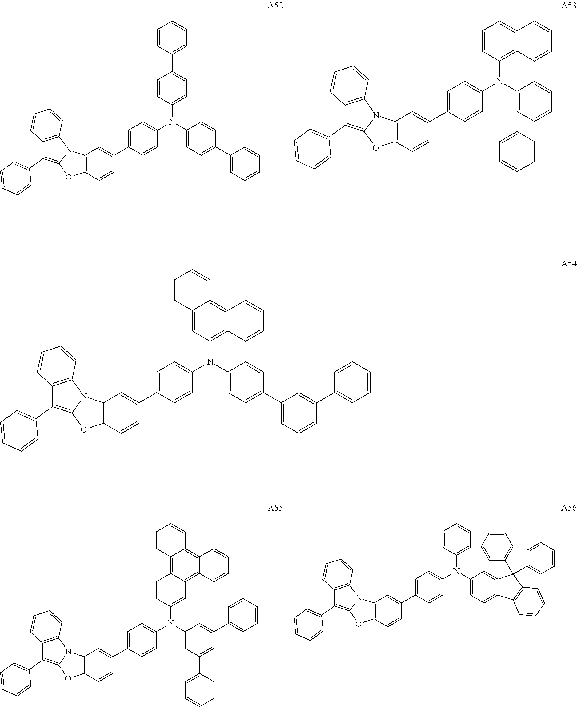


Applications Claiming Priority (2)
| Application Number | Priority Date | Filing Date | Title |
|---|---|---|---|
| KR10-2018-0121336 | 2018-10-11 | ||
| KR1020180121336A KR20200041422A (en) | 2018-10-11 | 2018-10-11 | Organic electroluminescence device and amine compound for organic electroluminescence device |
Publications (2)
| Publication Number | Publication Date |
|---|---|
| US20200119283A1 US20200119283A1 (en) | 2020-04-16 |
| US11264573B2 true US11264573B2 (en) | 2022-03-01 |
Family
ID=70160221
Family Applications (1)
| Application Number | Title | Priority Date | Filing Date |
|---|---|---|---|
| US16/454,465 Active 2040-08-28 US11264573B2 (en) | 2018-10-11 | 2019-06-27 | Organic electroluminescence device and amine compound for organic electroluminescence device |
Country Status (3)
| Country | Link |
|---|---|
| US (1) | US11264573B2 (en) |
| KR (1) | KR20200041422A (en) |
| CN (1) | CN111039956B (en) |
Families Citing this family (1)
| Publication number | Priority date | Publication date | Assignee | Title |
|---|---|---|---|---|
| KR20200113084A (en) * | 2019-03-21 | 2020-10-06 | 삼성디스플레이 주식회사 | Organic electroluminescence device and monoamine compound for organic electroluminescence device |
Citations (9)
| Publication number | Priority date | Publication date | Assignee | Title |
|---|---|---|---|---|
| CN103476774A (en) | 2011-04-13 | 2013-12-25 | 默克专利有限公司 | Materials for electronic devices |
| US20160043334A1 (en) | 2013-03-29 | 2016-02-11 | Konica Minolta, Inc. | Material for organic electroluminescent elements, organic electroluminescent element, display device and lighting device |
| WO2016036171A1 (en) | 2014-09-04 | 2016-03-10 | Rohm And Haas Electronic Materials Korea Ltd. | A plurality of host materials and organic electroluminescent devices comprising the same |
| KR20160028979A (en) | 2014-09-04 | 2016-03-14 | 롬엔드하스전자재료코리아유한회사 | A plurality of host materials and organic electroluminescence devices comprising the same |
| KR20160037788A (en) | 2014-09-29 | 2016-04-06 | 롬엔드하스전자재료코리아유한회사 | Organic Electroluminescent Compounds and Organic Electroluminescent Device Comprising the Same |
| KR101622828B1 (en) | 2014-04-16 | 2016-05-19 | 주식회사 두산 | Organic compounds and organic electro luminescence device comprising the same |
| JP2016219490A (en) | 2015-05-15 | 2016-12-22 | コニカミノルタ株式会社 | Organic electroluminescent element, display device and illuminating device |
| US20190074449A1 (en) * | 2017-09-07 | 2019-03-07 | Universal Display Corporation | Organic electroluminescent materials and devices |
| US20190252623A1 (en) * | 2018-02-09 | 2019-08-15 | Universal Display Corporation | Organic electroluminescent materials and devices |
Family Cites Families (4)
| Publication number | Priority date | Publication date | Assignee | Title |
|---|---|---|---|---|
| KR101477344B1 (en) * | 2012-07-09 | 2014-12-29 | 주식회사 두산 | Novel compound and organic electroluminescent device comprising the same |
| KR101740486B1 (en) * | 2012-07-25 | 2017-05-29 | 삼성디스플레이 주식회사 | Heteroring compound and organic light-emitting device including the same |
| KR101599597B1 (en) * | 2014-01-23 | 2016-03-03 | 주식회사 두산 | Organic compounds and organic electro luminescence device comprising the same |
| US11174259B2 (en) * | 2017-06-23 | 2021-11-16 | Universal Display Corporation | Organic electroluminescent materials and devices |
-
2018
- 2018-10-11 KR KR1020180121336A patent/KR20200041422A/en not_active Application Discontinuation
-
2019
- 2019-06-27 US US16/454,465 patent/US11264573B2/en active Active
- 2019-08-09 CN CN201910734053.9A patent/CN111039956B/en active Active
Patent Citations (13)
| Publication number | Priority date | Publication date | Assignee | Title |
|---|---|---|---|---|
| CN103476774A (en) | 2011-04-13 | 2013-12-25 | 默克专利有限公司 | Materials for electronic devices |
| US20140027755A1 (en) | 2011-04-13 | 2014-01-30 | Merck Patent Gmbh Patents & Scientific Information | Materials for electronic devices |
| US20160043334A1 (en) | 2013-03-29 | 2016-02-11 | Konica Minolta, Inc. | Material for organic electroluminescent elements, organic electroluminescent element, display device and lighting device |
| JP6269655B2 (en) | 2013-03-29 | 2018-01-31 | コニカミノルタ株式会社 | ORGANIC ELECTROLUMINESCENT ELEMENT MATERIAL, ORGANIC ELECTROLUMINESCENT ELEMENT, DISPLAY DEVICE AND LIGHTING DEVICE |
| KR101798307B1 (en) | 2013-03-29 | 2017-11-15 | 코니카 미놀타 가부시키가이샤 | Material for organic electroluminescent elements, organic electroluminescent element, display device and lighting device |
| KR101622828B1 (en) | 2014-04-16 | 2016-05-19 | 주식회사 두산 | Organic compounds and organic electro luminescence device comprising the same |
| KR20160028979A (en) | 2014-09-04 | 2016-03-14 | 롬엔드하스전자재료코리아유한회사 | A plurality of host materials and organic electroluminescence devices comprising the same |
| WO2016036171A1 (en) | 2014-09-04 | 2016-03-10 | Rohm And Haas Electronic Materials Korea Ltd. | A plurality of host materials and organic electroluminescent devices comprising the same |
| KR20160037788A (en) | 2014-09-29 | 2016-04-06 | 롬엔드하스전자재료코리아유한회사 | Organic Electroluminescent Compounds and Organic Electroluminescent Device Comprising the Same |
| US9997724B2 (en) | 2014-09-29 | 2018-06-12 | Rohm And Haas Electronic Materials Korea Ltd. | Organic electroluminescent compound and organic electroluminescent device comprising the same |
| JP2016219490A (en) | 2015-05-15 | 2016-12-22 | コニカミノルタ株式会社 | Organic electroluminescent element, display device and illuminating device |
| US20190074449A1 (en) * | 2017-09-07 | 2019-03-07 | Universal Display Corporation | Organic electroluminescent materials and devices |
| US20190252623A1 (en) * | 2018-02-09 | 2019-08-15 | Universal Display Corporation | Organic electroluminescent materials and devices |
Also Published As
| Publication number | Publication date |
|---|---|
| US20200119283A1 (en) | 2020-04-16 |
| CN111039956B (en) | 2023-12-15 |
| CN111039956A (en) | 2020-04-21 |
| KR20200041422A (en) | 2020-04-22 |
Similar Documents
| Publication | Publication Date | Title |
|---|---|---|
| US11489125B2 (en) | Organic electroluminescence device and monoamine compound for organic electroluminescence device | |
| US20200185626A1 (en) | Organic electroluminescence device and polycyclic compound for organic electroluminescence device | |
| US11165029B2 (en) | Amine compound and organic electroluminescence device including the same | |
| US20190319196A1 (en) | Organic electroluminescence device and nitrogen-containing compound for organic electroluminescence device | |
| US10673000B2 (en) | Heterocyclic compound and organic electroluminescence device including the same | |
| US11502259B2 (en) | Organic electroluminescence device and polycyclic compound for organic electroluminescence device | |
| US11276836B2 (en) | Organic electroluminescence device and polycyclic compound for organic electroluminescence device | |
| US10580993B2 (en) | Amine compound and organic electroluminescence device including the same | |
| US11825744B2 (en) | Organic electroluminescence device and condensed cyclic compound for organic electroluminescence device | |
| US20210104676A1 (en) | Luminescence device and polycyclic compound for luminescence device | |
| US20200052224A1 (en) | Organic electroluminescence device and condensed cyclic compound for organic electroluminescence device | |
| US11871651B2 (en) | Organic electroluminescence device and polycyclic compound for organic electroluminescence device | |
| US11737355B2 (en) | Organic electroluminescence device and amine compound for organic electroluminescence device | |
| US10777753B2 (en) | Heterocyclic compound and organic electroluminescence device including the same | |
| US20190207117A1 (en) | Organic electroluminescence device and monoamine compound for organic electroluminescence device | |
| US20210013430A1 (en) | Organic electroluminescence device and fused polycyclic compound for organic electroluminescence device | |
| US11393985B2 (en) | Organic electroluminescence device and polycyclic compound for organic electroluminescence device | |
| US11264573B2 (en) | Organic electroluminescence device and amine compound for organic electroluminescence device | |
| US11165026B2 (en) | Heterocyclic compound and organic electroluminescence device including the same | |
| US11515486B2 (en) | Organic electroluminescence device and polycyclic compound for organic electroluminescence device | |
| US20200185605A1 (en) | Organic electroluminescence device and polycyclic compound for organic electroluminescence device | |
| US20210104675A1 (en) | Luminescence device and polycyclic compound for luminescence device | |
| US20210320257A1 (en) | Organic electroluminescence device and fused polycyclic compound for organic electroluminescence device | |
| US20200403164A1 (en) | Organic electroluminescence device and amine compound for organic electroluminescence device | |
| US20210057652A1 (en) | Organic electroluminescence device and polycyclic compound for organic electroluminescence device |
Legal Events
| Date | Code | Title | Description |
|---|---|---|---|
| AS | Assignment |
Owner name: SAMSUNG DISPLAY CO., LTD., KOREA, REPUBLIC OF Free format text: ASSIGNMENT OF ASSIGNORS INTEREST;ASSIGNOR:UNO, TAKUYA;REEL/FRAME:049610/0059 Effective date: 20190527 |
|
| FEPP | Fee payment procedure |
Free format text: ENTITY STATUS SET TO UNDISCOUNTED (ORIGINAL EVENT CODE: BIG.); ENTITY STATUS OF PATENT OWNER: LARGE ENTITY |
|
| STPP | Information on status: patent application and granting procedure in general |
Free format text: NOTICE OF ALLOWANCE MAILED -- APPLICATION RECEIVED IN OFFICE OF PUBLICATIONS |
|
| STCF | Information on status: patent grant |
Free format text: PATENTED CASE |
|
| CC | Certificate of correction |