US11264553B2 - Overheat detection system and insulation muff comprising an overheat detection system - Google Patents
Overheat detection system and insulation muff comprising an overheat detection system Download PDFInfo
- Publication number
- US11264553B2 US11264553B2 US16/421,844 US201916421844A US11264553B2 US 11264553 B2 US11264553 B2 US 11264553B2 US 201916421844 A US201916421844 A US 201916421844A US 11264553 B2 US11264553 B2 US 11264553B2
- Authority
- US
- United States
- Prior art keywords
- insulation
- muff
- thermometer
- detection system
- module
- Prior art date
- Legal status (The legal status is an assumption and is not a legal conclusion. Google has not performed a legal analysis and makes no representation as to the accuracy of the status listed.)
- Active, expires
Links
Images


Classifications
-
- H—ELECTRICITY
- H10—SEMICONDUCTOR DEVICES; ELECTRIC SOLID-STATE DEVICES NOT OTHERWISE PROVIDED FOR
- H10N—ELECTRIC SOLID-STATE DEVICES NOT OTHERWISE PROVIDED FOR
- H10N10/00—Thermoelectric devices comprising a junction of dissimilar materials, i.e. devices exhibiting Seebeck or Peltier effects
- H10N10/80—Constructional details
- H10N10/81—Structural details of the junction
-
- H01L35/04—
-
- G—PHYSICS
- G01—MEASURING; TESTING
- G01K—MEASURING TEMPERATURE; MEASURING QUANTITY OF HEAT; THERMALLY-SENSITIVE ELEMENTS NOT OTHERWISE PROVIDED FOR
- G01K1/00—Details of thermometers not specially adapted for particular types of thermometer
- G01K1/02—Means for indicating or recording specially adapted for thermometers
- G01K1/024—Means for indicating or recording specially adapted for thermometers for remote indication
-
- B—PERFORMING OPERATIONS; TRANSPORTING
- B64—AIRCRAFT; AVIATION; COSMONAUTICS
- B64D—EQUIPMENT FOR FITTING IN OR TO AIRCRAFT; FLIGHT SUITS; PARACHUTES; ARRANGEMENTS OR MOUNTING OF POWER PLANTS OR PROPULSION TRANSMISSIONS IN AIRCRAFT
- B64D13/00—Arrangements or adaptations of air-treatment apparatus for aircraft crew or passengers, or freight space, or structural parts of the aircraft
- B64D13/06—Arrangements or adaptations of air-treatment apparatus for aircraft crew or passengers, or freight space, or structural parts of the aircraft the air being conditioned
- B64D13/08—Arrangements or adaptations of air-treatment apparatus for aircraft crew or passengers, or freight space, or structural parts of the aircraft the air being conditioned the air being heated or cooled
-
- B—PERFORMING OPERATIONS; TRANSPORTING
- B64—AIRCRAFT; AVIATION; COSMONAUTICS
- B64D—EQUIPMENT FOR FITTING IN OR TO AIRCRAFT; FLIGHT SUITS; PARACHUTES; ARRANGEMENTS OR MOUNTING OF POWER PLANTS OR PROPULSION TRANSMISSIONS IN AIRCRAFT
- B64D15/00—De-icing or preventing icing on exterior surfaces of aircraft
- B64D15/02—De-icing or preventing icing on exterior surfaces of aircraft by ducted hot gas or liquid
- B64D15/04—Hot gas application
-
- G—PHYSICS
- G01—MEASURING; TESTING
- G01K—MEASURING TEMPERATURE; MEASURING QUANTITY OF HEAT; THERMALLY-SENSITIVE ELEMENTS NOT OTHERWISE PROVIDED FOR
- G01K1/00—Details of thermometers not specially adapted for particular types of thermometer
- G01K1/14—Supports; Fastening devices; Arrangements for mounting thermometers in particular locations
-
- G—PHYSICS
- G01—MEASURING; TESTING
- G01K—MEASURING TEMPERATURE; MEASURING QUANTITY OF HEAT; THERMALLY-SENSITIVE ELEMENTS NOT OTHERWISE PROVIDED FOR
- G01K17/00—Measuring quantity of heat
- G01K17/06—Measuring quantity of heat conveyed by flowing media, e.g. in heating systems e.g. the quantity of heat in a transporting medium, delivered to or consumed in an expenditure device
-
- G—PHYSICS
- G01—MEASURING; TESTING
- G01K—MEASURING TEMPERATURE; MEASURING QUANTITY OF HEAT; THERMALLY-SENSITIVE ELEMENTS NOT OTHERWISE PROVIDED FOR
- G01K3/00—Thermometers giving results other than momentary value of temperature
- G01K3/005—Circuits arrangements for indicating a predetermined temperature
-
- G—PHYSICS
- G01—MEASURING; TESTING
- G01K—MEASURING TEMPERATURE; MEASURING QUANTITY OF HEAT; THERMALLY-SENSITIVE ELEMENTS NOT OTHERWISE PROVIDED FOR
- G01K7/00—Measuring temperature based on the use of electric or magnetic elements directly sensitive to heat ; Power supply therefor, e.g. using thermoelectric elements
- G01K7/16—Measuring temperature based on the use of electric or magnetic elements directly sensitive to heat ; Power supply therefor, e.g. using thermoelectric elements using resistive elements
-
- H01L35/34—
-
- H—ELECTRICITY
- H10—SEMICONDUCTOR DEVICES; ELECTRIC SOLID-STATE DEVICES NOT OTHERWISE PROVIDED FOR
- H10N—ELECTRIC SOLID-STATE DEVICES NOT OTHERWISE PROVIDED FOR
- H10N10/00—Thermoelectric devices comprising a junction of dissimilar materials, i.e. devices exhibiting Seebeck or Peltier effects
- H10N10/01—Manufacture or treatment
-
- G—PHYSICS
- G01—MEASURING; TESTING
- G01K—MEASURING TEMPERATURE; MEASURING QUANTITY OF HEAT; THERMALLY-SENSITIVE ELEMENTS NOT OTHERWISE PROVIDED FOR
- G01K2215/00—Details concerning sensor power supply
Definitions
- Pneumatic ducting in aircraft runs along the pylon, wing and fuselage to drive hot air from the engines and the APU to the wing anti-ice and air conditioning packs.
- This routing is made of insulated titanium ducts clamped to each other.
- Each duct junction is insulated with a flexible insulation, fixed with Velcro or cord, wrapped around it (also called “muff” or “insulation muff”).
- an insulation muff comprises an inner covering film, an outer covering film, an insulation material in between and a venting hole to allow hot air flow leakage from the duct to be directed towards overheat sensors and, in that way, to detect the leak.
- They may also comprise a flow guidance device (such as a venting grid) able to provide a homogeneous flow towards the overheat sensors.
- the Overheat Detection System ensures fast leak and burst detection, in order to isolate the system and protect the surrounding structure and systems.
- the early detection of hot air leakages in aircraft systems is very important to prevent any damage to the structure and components, and fire and/or explosions in the fuel tanks of the aircraft, which could result from duct leak or rupture.
- the current OHDS is composed of linear sensors, mainly “eutectic salt” sensors, running along the pipe, and wired to an interrogator.
- These “eutectic salt” sensors are basically constituted by a rigid coaxial cable (typically made of nickel) with a salt that changes electrical resistance when heated. As a leak of hot air happens, it is directed onto the sensor by the venting holes in the outer cover of the duct insulation muff. Accordingly, the local electrical resistance of the salt changes, which is detected by the interrogator.
- This OHDS with eutectic salt sensors does not allow an accurate localization of the defect, and is also very subject to false alarms and open circuits, which heavily affect the reliability. Additionally, the sensors are fairly difficult and sensitive to install, due to the rigidity of the cables.
- OHDS are based on optical-fiber elements.
- the fiber contains FBG (Fiber Bragg Grating) elements which reflect a specific wavelength. That wavelength changes with temperature.
- FBG Fiber Bragg Grating
- the interrogator can measure the temperature of each point of the fiber. Those sensing elements must be wired to the interrogator by optical fiber.
- An object of the present invention is to provide an OHDS that overcomes the drawbacks existing in the prior art systems.
- the invention provides an overheat detection system comprising:
- thermometer
- thermal harvesting module comprising at least one passive radiator, the thermal harvesting module being able to generate electrical energy from the thermal difference between two elements, and
- a digital module comprising means for power management, means for data treatment and means for wireless transmission,
- thermometer wherein the electrical energy generated by the thermal harvesting module powers the thermometer and the digital module.
- the OHDS of the invention allows the removal of all or most of the cables, the accurate localization of the defect, and improves reliability with respect to the current eutectic salt.
- Another advantage of the invention is that it requires low maintenance, as no battery is needed.
- the invention also provides an insulation muff comprising an inner cover, an outer cover, an insulation material in between and a venting hole to guide hot air flow leakages from the duct on which the insulation muff is intended to be installed, that additionally comprises an overheat detection system integrated in the insulation muff at the location of the venting hole, wherein the thermal harvesting module, the thermometer and the digital module are integrated into a housing.
- an insulation muff comprising an inner cover, an outer cover, an insulation material in between and a venting hole to guide hot air flow leakages from the duct on which the insulation muff is intended to be installed, that additionally comprises an overheat detection system, wherein the part of the overheat detection system comprising the thermometer and the digital module is integrated in the insulation muff at the location of the venting hole.
- FIG. 1 shows a schematic view of a leak in a hot air duct with an insulation muff.
- FIG. 2 shows a schematic view of the operation of an OHDS of the invention on a hot air duct.
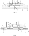
- FIG. 3 shows a cross section of an OHDS of the invention, an insulation muff of the invention and the hot air duct on which they are installed.
- FIG. 4 shows a cross section of another embodiment of an OHDS of the invention, another embodiment of an insulation muff of the invention and the hot air duct on which they are installed.
- FIG. 1 shows a typical view of a leak 4 in a hot air duct 2 with an insulation muff 3 .
- the venting hole 5 of the insulation muff 3 allows that the leak 4 of hot air flow is directed outwards, specifically towards sensing elements (not shown in this figure).
- each duct 2 can be made to direct any leak 4 towards the nearest duct junction, where the hot leaked air will pass through the venting hole 5 of the insulation muff 3 .
- FIG. 2 shows a general view of the elements and the operation of an OHDS 1 , 1 ′ of the invention on a hot air duct 2 .
- the OHDS 1 , 1 ′ comprises a thermal harvesting module 6 that generates low power from the thermal difference between the hot air duct 2 and the surrounding air. It powers a thermometer 7 as well as a digital module 8 with means for wireless transmission, which can perform wireless data transmission to a receiver 9 (wired to the avionics).
- the general configuration of the OHDS 1 , 1 ′ of the invention comprises:
- thermometer 7 a thermometer 7 .
- thermal harvesting module 6 comprising at least one passive radiator 12 , the thermal harvesting module 6 being able to generate electrical energy from the thermal difference between two elements, and
- a digital module 8 comprising means for power management, means for data treatment and means for wireless transmission,
- thermometer 7 wherein the electrical energy generated by the thermal harvesting module 6 powers the thermometer 7 and the digital module 8 .
- FIG. 3 shows a cross section of an OHDS 1 of the invention, an insulation muff 3 of the invention and the hot air duct 2 on which they are installed (only the upper part of the cross section is shown).
- the OHDS 1 of FIG. 3 is installed as part of the cover of the insulation muff 3 , at the location of the venting hole 5 . As it is integrated into the cover, it is installed at the same time, without any additional operation, so its installation is easy and quick.
- the thermal harvesting module 6 is equipped with at least one passive radiator 12 (for instance, two passive radiators 12 , one on each side) to ensure thermal exchange from the hot air below the insulation muff 3 to the ambient air. If the difference of temperatures is high enough, it may be possible to have only one passive radiator 12 in the thermal harvesting module 6 .
- thermometer 7 is installed at the venting hole 5 location, away enough from the duct 2 to ensure measurement of the eventual leakage hot air flow, and not of normal heating from the duct 2 .
- the digital module 8 comprises the means for power management (including means for voltage transformation, and means for storing of the energy for some limited time, for instance using a condenser), means for data treatment (eventually with a low-energy microcontroller if necessary), and means for wireless transmission.
- the wireless transmission can be using an available network (such as WAIC: Wireless Avionics Intra-Communication), or communicating with a specific receiver 9 that is wired to the avionics.
- WAIC Wireless Avionics Intra-Communication
- all the components of the OHDS 1 can be integrated in a housing 10 (for instance, a small rigid case), sewed on the insulation muff 3 .
- the insulation muff 3 of FIG. 3 can comprise an inner cover, an outer cover, an insulation material in between and a venting hole 5 to guide hot air flow leakages from the duct 2 on which the insulation muff 3 is intended to be installed, and additionally comprises an overheat detection system 1 as described integrated in the insulation muff 3 at the location of the venting hole 5 .
- FIG. 4 shows a cross section of another embodiment of an OHDS 1 ′ of the invention, another embodiment of an insulation muff 3 of the invention and the hot air duct 2 on which they are installed.
- the hot side of the thermal harvesting module 6 can be in contact with the duct 2 metal directly, if the thermal generation cannot produce sufficient power using two passive radiators 12 .
- thermo harvesting module 6 is separated from the rest of the system that comprises the thermometer 7 and the digital module 8 .
- the thermal harvesting module 6 is put in contact with the duct 2 metal, and a radiator 12 is used on the cold side. It is connected to the rest of the system by a cable 11 .
- This configuration needs a special shape on the duct 2 , with a flat surface accessible through a space in the duct insulation.
- the insulation muff 3 of FIG. 4 can comprise an inner cover, an outer cover, an insulation material in between and a venting hole 5 to guide hot air flow leakages from the duct 2 on which the insulation muff 3 is intended to be installed, and additionally comprises an overheat detection system 1 ′ wherein the part of the overheat detection system 1 ′ comprising the thermometer 7 and the digital module 8 is integrated in the insulation muff 3 at the location of the venting hole 5 .
Abstract
Description
Claims (7)
Applications Claiming Priority (3)
| Application Number | Priority Date | Filing Date | Title |
|---|---|---|---|
| EP18382371.5 | 2018-05-30 | ||
| EP18382371.5A EP3575761A1 (en) | 2018-05-30 | 2018-05-30 | Overheat detection system and insulation muff comprising an overheat detection system |
| EP18382371 | 2018-05-30 |
Publications (2)
| Publication Number | Publication Date |
|---|---|
| US20190371993A1 US20190371993A1 (en) | 2019-12-05 |
| US11264553B2 true US11264553B2 (en) | 2022-03-01 |
Family
ID=62567586
Family Applications (1)
| Application Number | Title | Priority Date | Filing Date |
|---|---|---|---|
| US16/421,844 Active 2039-06-19 US11264553B2 (en) | 2018-05-30 | 2019-05-24 | Overheat detection system and insulation muff comprising an overheat detection system |
Country Status (3)
| Country | Link |
|---|---|
| US (1) | US11264553B2 (en) |
| EP (1) | EP3575761A1 (en) |
| CN (1) | CN110553759A (en) |
Citations (11)
| Publication number | Priority date | Publication date | Assignee | Title |
|---|---|---|---|---|
| DE19724769A1 (en) | 1997-06-12 | 1998-12-17 | D T S Ges Zur Fertigung Von Du | Energy self-sufficient sensor system for detecting unwanted heat |
| US20020145538A1 (en) * | 2001-01-30 | 2002-10-10 | Bocko Mark F. | Autonomous sensor system for remote sensing and signal transmission |
| DE10344553A1 (en) | 2003-09-24 | 2005-04-28 | Behr Gmbh & Co Kg | Sensor set up e.g. for temperature, air current velocity in motor vehicle, has power supply which is connected to thermal generator which produces signal due to temperature difference between interior of air duct |
| US20090184829A1 (en) | 2008-01-22 | 2009-07-23 | Rivers Jr Cecil | Temperature sensor |
| US20100177801A1 (en) * | 2009-01-15 | 2010-07-15 | William Preston Geren | Methods and systems for passive, wireless temperature monitoring |
| US20120018014A1 (en) * | 2010-07-21 | 2012-01-26 | Leslie Fernandes | Joint Cover with Manifold for Duct Leak Detection System |
| EP2818783A1 (en) | 2013-06-28 | 2014-12-31 | Airbus Operations, S.L. | Flow guidance device for insulation muff venting holes |
| US8963691B1 (en) * | 2010-07-27 | 2015-02-24 | The Boeing Company | Sensor association system using wireless device information |
| US20160332501A1 (en) * | 2014-07-31 | 2016-11-17 | The Boeing Company | Systems and methods for duct protection of a vehicle |
| US20170370516A1 (en) * | 2016-06-24 | 2017-12-28 | The Boeing Company | Systems and methods for duct protection |
| US10559737B2 (en) * | 2015-10-13 | 2020-02-11 | Fujitsu Limited | Method for producing thermoelectric conversion apparatus and thermoelectric conversion apparatus |
-
2018
- 2018-05-30 EP EP18382371.5A patent/EP3575761A1/en not_active Withdrawn
-
2019
- 2019-05-24 US US16/421,844 patent/US11264553B2/en active Active
- 2019-05-28 CN CN201910451038.3A patent/CN110553759A/en active Pending
Patent Citations (11)
| Publication number | Priority date | Publication date | Assignee | Title |
|---|---|---|---|---|
| DE19724769A1 (en) | 1997-06-12 | 1998-12-17 | D T S Ges Zur Fertigung Von Du | Energy self-sufficient sensor system for detecting unwanted heat |
| US20020145538A1 (en) * | 2001-01-30 | 2002-10-10 | Bocko Mark F. | Autonomous sensor system for remote sensing and signal transmission |
| DE10344553A1 (en) | 2003-09-24 | 2005-04-28 | Behr Gmbh & Co Kg | Sensor set up e.g. for temperature, air current velocity in motor vehicle, has power supply which is connected to thermal generator which produces signal due to temperature difference between interior of air duct |
| US20090184829A1 (en) | 2008-01-22 | 2009-07-23 | Rivers Jr Cecil | Temperature sensor |
| US20100177801A1 (en) * | 2009-01-15 | 2010-07-15 | William Preston Geren | Methods and systems for passive, wireless temperature monitoring |
| US20120018014A1 (en) * | 2010-07-21 | 2012-01-26 | Leslie Fernandes | Joint Cover with Manifold for Duct Leak Detection System |
| US8963691B1 (en) * | 2010-07-27 | 2015-02-24 | The Boeing Company | Sensor association system using wireless device information |
| EP2818783A1 (en) | 2013-06-28 | 2014-12-31 | Airbus Operations, S.L. | Flow guidance device for insulation muff venting holes |
| US20160332501A1 (en) * | 2014-07-31 | 2016-11-17 | The Boeing Company | Systems and methods for duct protection of a vehicle |
| US10559737B2 (en) * | 2015-10-13 | 2020-02-11 | Fujitsu Limited | Method for producing thermoelectric conversion apparatus and thermoelectric conversion apparatus |
| US20170370516A1 (en) * | 2016-06-24 | 2017-12-28 | The Boeing Company | Systems and methods for duct protection |
Non-Patent Citations (1)
| Title |
|---|
| European Search Report; priority document. |
Also Published As
| Publication number | Publication date |
|---|---|
| US20190371993A1 (en) | 2019-12-05 |
| CN110553759A (en) | 2019-12-10 |
| EP3575761A1 (en) | 2019-12-04 |
Similar Documents
| Publication | Publication Date | Title |
|---|---|---|
| US8708554B2 (en) | Leak detection apparatus for aircraft bleed air systems | |
| RU2561242C2 (en) | Coupling jacket and manifold for pipes | |
| CN101761391B (en) | Bleed leakage detection system and method | |
| US11599176B2 (en) | Power converter failure detection and prevention | |
| EP3421944B1 (en) | Housing of sensor and sensor | |
| EP3291192A1 (en) | Monitoring system of an aircraft bleed air system | |
| BRPI0709752A2 (en) | cabling arrangement to protect an aircraft's drain air supply system from overheating, and drain air supply system | |
| US10345190B2 (en) | Method for detecting a fluid leak in a turbomachine and fluid distribution system | |
| BR102018008238A2 (en) | temperature detection fiber optic cable, system configured for temperature monitoring, and method for replacing a first modular fiber optic cable. | |
| US11264553B2 (en) | Overheat detection system and insulation muff comprising an overheat detection system | |
| JP5677519B2 (en) | Temperature detection device | |
| US3864960A (en) | Vacuum leak detector | |
| US20080042857A1 (en) | Fire Warning System | |
| JP2010230165A (en) | Insulating protective element of piping | |
| EP0175698B1 (en) | High speed hot air leak sensor | |
| WO2013172730A1 (en) | A system for monitoring the condition of a pipeline for gas and/or fluid | |
| CN105121845B (en) | It is related to the improvement of wind turbine sensor | |
| CN216894642U (en) | Cooling device and aeroengine test system | |
| US20230108788A1 (en) | Assembly comprising two concentric tubular portions and a set of sensors for sensing thermal flow inside the outer tubular portion | |
| CN219777545U (en) | Thermal insulation performance testing device | |
| CN219300227U (en) | System based on unmanned aerial vehicle pipeline detects | |
| CN215952796U (en) | Sensor and aircraft engine comprising same | |
| US11551483B2 (en) | Systems and methods for early detection of pneumatic transport element leaks | |
| JP2021139712A (en) | Temperature abnormality surveillance method and temperature abnormality surveillance device of electric board | |
| EP2818783A1 (en) | Flow guidance device for insulation muff venting holes |
Legal Events
| Date | Code | Title | Description |
|---|---|---|---|
| FEPP | Fee payment procedure |
Free format text: ENTITY STATUS SET TO UNDISCOUNTED (ORIGINAL EVENT CODE: BIG.); ENTITY STATUS OF PATENT OWNER: LARGE ENTITY |
|
| STPP | Information on status: patent application and granting procedure in general |
Free format text: DOCKETED NEW CASE - READY FOR EXAMINATION |
|
| STPP | Information on status: patent application and granting procedure in general |
Free format text: NON FINAL ACTION MAILED |
|
| STPP | Information on status: patent application and granting procedure in general |
Free format text: RESPONSE TO NON-FINAL OFFICE ACTION ENTERED AND FORWARDED TO EXAMINER |
|
| STPP | Information on status: patent application and granting procedure in general |
Free format text: FINAL REJECTION MAILED |
|
| STPP | Information on status: patent application and granting procedure in general |
Free format text: RESPONSE AFTER FINAL ACTION FORWARDED TO EXAMINER |
|
| STPP | Information on status: patent application and granting procedure in general |
Free format text: ADVISORY ACTION MAILED |
|
| STPP | Information on status: patent application and granting procedure in general |
Free format text: RESPONSE AFTER FINAL ACTION FORWARDED TO EXAMINER |
|
| STPP | Information on status: patent application and granting procedure in general |
Free format text: NOTICE OF ALLOWANCE MAILED -- APPLICATION RECEIVED IN OFFICE OF PUBLICATIONS |
|
| AS | Assignment |
Owner name: AIRBUS OPERATIONS S.L., SPAIN Free format text: ASSIGNMENT OF ASSIGNORS INTEREST;ASSIGNORS:LENOIR, BRICE;MOURTIS IOANNOU, PANAGIOTIS;SIGNING DATES FROM 20190411 TO 20211220;REEL/FRAME:058446/0956 |
|
| STCF | Information on status: patent grant |
Free format text: PATENTED CASE |