US11262126B2 - Drying system for a vehicle - Google Patents
Drying system for a vehicle Download PDFInfo
- Publication number
- US11262126B2 US11262126B2 US16/539,301 US201916539301A US11262126B2 US 11262126 B2 US11262126 B2 US 11262126B2 US 201916539301 A US201916539301 A US 201916539301A US 11262126 B2 US11262126 B2 US 11262126B2
- Authority
- US
- United States
- Prior art keywords
- airflow
- duct
- vehicle
- window
- intake duct
- Prior art date
- Legal status (The legal status is an assumption and is not a legal conclusion. Google has not performed a legal analysis and makes no representation as to the accuracy of the status listed.)
- Active, expires
Links
Images


Classifications
-
- F—MECHANICAL ENGINEERING; LIGHTING; HEATING; WEAPONS; BLASTING
- F26—DRYING
- F26B—DRYING SOLID MATERIALS OR OBJECTS BY REMOVING LIQUID THEREFROM
- F26B19/00—Machines or apparatus for drying solid materials or objects not covered by groups F26B9/00 - F26B17/00
- F26B19/005—Self-contained mobile devices, e.g. for agricultural produce
-
- F—MECHANICAL ENGINEERING; LIGHTING; HEATING; WEAPONS; BLASTING
- F26—DRYING
- F26B—DRYING SOLID MATERIALS OR OBJECTS BY REMOVING LIQUID THEREFROM
- F26B21/00—Arrangements for supplying or controlling air or other gases for drying solid materials or objects
- F26B21/001—Air generating units, e.g. movable or independent of drying enclosure
-
- F—MECHANICAL ENGINEERING; LIGHTING; HEATING; WEAPONS; BLASTING
- F26—DRYING
- F26B—DRYING SOLID MATERIALS OR OBJECTS BY REMOVING LIQUID THEREFROM
- F26B21/00—Arrangements for supplying or controlling air or other gases for drying solid materials or objects
- F26B21/50—Ducting arrangements from the source of air or other gases to the materials or objects being dried
-
- F—MECHANICAL ENGINEERING; LIGHTING; HEATING; WEAPONS; BLASTING
- F26—DRYING
- F26B—DRYING SOLID MATERIALS OR OBJECTS BY REMOVING LIQUID THEREFROM
- F26B3/00—Drying solid materials or objects by processes involving the application of heat
- F26B3/02—Drying solid materials or objects by processes involving the application of heat by convection, i.e. heat being conveyed from a heat source to the materials or objects to be dried by a gas or vapour, e.g. air
- F26B3/06—Drying solid materials or objects by processes involving the application of heat by convection, i.e. heat being conveyed from a heat source to the materials or objects to be dried by a gas or vapour, e.g. air the gas or vapour flowing through the materials or objects to be dried
-
- F—MECHANICAL ENGINEERING; LIGHTING; HEATING; WEAPONS; BLASTING
- F26—DRYING
- F26B—DRYING SOLID MATERIALS OR OBJECTS BY REMOVING LIQUID THEREFROM
- F26B9/00—Machines or apparatus for drying solid materials or objects at rest or with only local agitation; Domestic airing cupboards
- F26B9/003—Small self-contained devices, e.g. portable
Definitions
- the present invention relates to vehicle accessories and, more particularly, to a system mountable in a vehicle interior for drying wet articles.
- Items such as towels and clothing may become wet due to rain or participation of a user in recreational activities.
- the user may wish to dry such items as rapidly and as conveniently as possible.
- an extended period of time may elapse before the user can drive home or move to an area where wet items of clothing can be dried in a conventional, possibly time-consuming manner.
- a drying system for a vehicle includes an airflow intake duct structured to be mountable to the vehicle so as to reside exterior of the vehicle.
- the airflow intake duct includes an intake duct airflow passage structured to receive an airflow therein from outside the vehicle when the vehicle is moving.
- An airflow duct is structured to be coupled to the intake duct so as to reside in an interior of the vehicle and so as to receive therein the airflow from the intake duct when the intake duct is mounted exterior of the vehicle.
- the airflow duct includes a plurality of holes structured to enable discharge a portion of the airflow from the airflow duct into the interior of the vehicle.
- FIG. 1 is a schematic perspective view of a vehicle incorporating a system structured for drying articles in an interior of a vehicle, in accordance with an embodiment described herein.
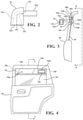
- FIG. 2 is a schematic plan view of an airflow intake duct in accordance with an embodiment described herein.
- FIG. 3 is a schematic edge view of a portion of a vehicle door viewed from in front of the vehicle, showing mounting of a window adapter on the door and an airflow intake duct on the window adapter.
- FIG. 4 is a schematic side view of the door shown in FIG. 3 .
- FIG. 5 is a schematic end view of a vehicle including opposed vehicle doors with window adapters mounted on the door windows for supporting a drying airflow duct therebetween, as viewed from in front of the vehicle.
- Embodiments described herein relate to a drying system for a vehicle.
- the drying system may include an airflow intake duct structured to be mountable to the vehicle so as to reside exterior of the vehicle.
- the airflow intake duct may include an intake duct airflow passage structured to receive an airflow therein from outside the vehicle when the vehicle is moving.
- An airflow duct is structured to be coupled to the intake duct so as to reside in an interior of the vehicle and so as to receive therein the airflow from the intake duct when the intake duct is mounted exterior of the vehicle.
- the airflow duct may include a plurality of holes structured to enable discharge a portion of the airflow from the airflow duct into the interior of the vehicle.
- Wet items such as towels or clothing may be hung over or near the airflow duct in the vehicle interior, to be dried by air flowing from the airflow duct holes.
- an impeller or fan may be incorporated into the drying system to increase air circulation.
- FIG. 1 is a schematic perspective view of a vehicle incorporating a system 20 structured for drying articles in an interior of a vehicle, in accordance with an embodiment described herein.
- the drying system 20 may include an airflow intake duct 22 .
- the airflow intake duct 22 may define an intake duct airflow passage 22 a structured to receive an airflow therein from outside the vehicle 18 when the vehicle is moving.
- Airflow intake duct 22 may define an intake duct entrance 22 b structured to receive the airflow therein.
- An intake duct exit 22 c may be spaced apart from the intake duct entrance 22 b .
- the intake duct airflow passage 22 a may extend between the intake duct entrance 22 b and the intake duct exit 22 c.
- a cross-sectional area of the intake duct airflow passage 22 a may decrease proceeding in a direction D 1 from the intake duct entrance toward the intake duct exit 22 c .
- This narrowing of the intake duct airflow passage 22 a may have the effect of increasing the speed of the airflow entering the airflow duct 50 (described in greater detail below).
- a valve may be mounted on the airflow intake duct 22 to control the airflow 99 into the intake duct.
- the valve may be in the form of a rolling, shutter-type door 22 e positionable to block the intake duct entrance 22 b .
- the door 22 e may be securable in any of a variety of positions to control an open size of the intake duct entrance 22 b , thereby controlling a flow rate of air into the airflow intake duct 22 .
- other types of valves may be used to control airflow into the airflow intake duct 22 or through the airflow intake duct 22 into the airflow duct 50 .
- the airflow intake duct 22 may be structured to be mountable to the vehicle 18 so as to reside exterior of the vehicle, in a location selected to immerse the airflow intake duct 22 in an airflow passing over the vehicle 18 when the vehicle is moving. A portion 99 of the airflow passing over the vehicle 18 may then enter intake duct airflow passage 22 a through intake duct entrance 22 b.
- the airflow intake duct 22 may be mounted to the vehicle 18 using a first window adapter 24 .
- the first window adapter 24 may be structured to be mountable to a first vehicle window 26 so as to extend between the first vehicle window 26 and an uppermost portion 28 a of a first vehicle door 28 containing the first vehicle window, when the first vehicle window 26 is partially open.
- the first window adapter 24 may be structured to form a substantially airtight seal with the vehicle door 28 and the window 26 when the first window adapter 24 is mounted in the partially open window.
- the first window adapter 24 may include a planar body portion 24 a having a thickness equal to that of the window glass so that a first (upper) edge 24 b of the first window adapter 24 can fit into an existing window groove 28 b of the vehicle door 28 .
- a second edge 24 c of the first window adapter 24 may have a groove or slot 24 d formed therein. Groove 24 d may be structured to receive an uppermost edge of the window 26 therein in a slight interference fit.
- Other (i.e., front and rear) edges 24 e , 24 f FIG.
- the first window adapter 24 may be similarly structured to fit inside associated front and rear portions of the window groove 28 b of the vehicle door 28 .
- the first window adapter 24 may be formed from a suitable polymer, enabling edges of the adapters to be bent slightly to facilitate user insertion of the adapter edges into the window groove.
- the first window adapter 24 may also include a first window adapter airflow passage 24 m extending from a first side of the first window adapter through the first window adapter to a second side of the first window adapter opposite the first side.
- the first window adapter 24 may also include an intake duct mounting sleeve 24 p extending from the first window adapter 24 along the first side of the first window adapter and defining a portion of the first window adapter airflow passage 24 m .
- the intake duct mounting sleeve 24 p may be structured to receive therein a portion of the airflow intake duct 22 (for example, an intake duct nozzle 22 n ) for mounting the airflow intake duct 22 to the first window adapter 24 .
- the intake duct mounting sleeve 24 p may be structured to form a gas-tight seal with the intake duct nozzle 22 n when the airflow intake duct 22 is coupled to the intake duct mounting sleeve 24 p.
- the first window adapter 24 may also include an airflow duct mounting sleeve 24 s extending from the first window adapter 24 along the second side of the first window adapter and defining a portion of the first window adapter airflow passage 24 m .
- the airflow duct mounting sleeve 24 s may be structured to receive therein a first portion of the airflow duct 50 for mounting the airflow duct 50 to the first window adapter 24 .
- the first vehicle window 26 may be rolled partially down. Then, an upper edge of the window 26 may be inserted into adapter groove 24 d and adapter edges 24 e and 24 f may be inserted into the door window groove 28 b . The window 26 may then be rolled up until the upper edge 24 b of the adapter enters into the existing window groove 28 b of the vehicle door 28 .
- adapters having other structures may be used as long as they act to fill the gap between the partially-open window and the uppermost portion of the vehicle door, provide an airflow passage therethrough, and also enable mounting of an intake duct and an airflow duct thereto, either directly or indirectly.
- Airflow duct 50 may be structured to be coupled to the airflow intake duct 22 via airflow duct mounting sleeve 24 s and may be structured to form a gas-tight seal with the airflow duct mounting sleeve 24 s .
- the airflow duct 50 When coupled to airflow duct mounting sleeve 24 s , the airflow duct 50 may extend through an interior of the vehicle as shown in FIG. 5 . Airflow duct 50 may then receive the airflow 99 from the airflow intake duct 22 when the airflow intake duct 22 is mounted exterior of the vehicle 18 .
- the airflow duct 50 may include a plurality of holes 50 a structured to enable discharge of at least a portion of the airflow 99 from the airflow duct 50 into the interior of the vehicle. Thus, a portion of the airflow 99 may be discharged through holes 50 a to dry an item positioned proximate the airflow duct (for example, an item of clothing positioned to hang over the airflow duct 50 ).
- the airflow duct 50 may have a telescoping structure including at least a pair of telescoping members. This enables the length of the airflow duct 50 to be adjusted for different vehicle widths.
- airflow duct 50 may extend from first window adapter 24 into the vehicle interior in cantilever fashion. In this case, portions of the aiflow 99 not discharged through the airflow duct openings 50 a may be discharged from a free, open end of airflow duct 50 , into the vehicle interior and/or out of the vehicle through another open window.
- an end 50 b of the airflow duct 50 may be supported by engagement with a second window adapter 52 mounted on a second window 54 of the vehicle 18 .
- Second window 54 may be mounted in a second door 29 located opposite first door 28 . As shown in FIG.
- the second window adapter 52 may be structured to be mountable to second vehicle window 54 so as to extend between the second vehicle window 54 and a groove 29 b of an uppermost portion 29 a of a second vehicle door 29 containing the second vehicle window, when the second vehicle window 54 is partially open.
- the second window adapter 52 may be structured and mounted to the second vehicle window in the manner previously described with respect to the first window adapter 24 .
- the second window adapter 52 may be structured to form a substantially airtight seal with the second vehicle door 29 and the second window 54 when the adapter 52 is mounted in the partially open window.
- the second window adapter 52 may include a planar body 52 a portion a having a thickness equal to that of the window glass so that a first (upper) edge 52 b of the second window adapter 52 can fit into an existing window groove 29 b of the vehicle door 29 .
- a second edge 52 c of the second window adapter 52 may have a groove or slot 52 d formed therein. Groove 52 d may be structured to receive an uppermost edge of the window 54 therein in a slight interference fit.
- edges 52 e , 52 f may be similarly structured to fit inside associated front and rear portions of the window groove 29 b of the vehicle door 29 , as descried previously with respect to first window 26 of shown in FIG. 4 .
- the adapter 52 may be formed from a suitable polymer, enabling edges of the adapters to be bent slightly to facilitate user insertion of the adapter edges into the window groove.
- the second window adapter 52 may also include a second window adapter airflow passage 52 m extending from a first side of the second window adapter 52 through the second window adapter to a second side of the second window adapter opposite the first side.
- the second window adapter 52 may also include an airflow duct mounting sleeve 52 p extending from the second window adapter 52 along the first side of the second window adapter and defining a portion of the second window adapter airflow passage 52 m .
- the airflow duct mounting sleeve 52 p may be structured to receive therein a portion of the airflow duct 50 for mounting the airflow duct 50 to the second window adapter 52 .
- the airflow duct mounting sleeve 52 p may be structured to form a gas-tight seal with the airflow duct 50 when the airflow duct 50 is coupled to the airflow duct mounting sleeve 52 p .
- the second window adapter 52 may also include a discharge duct mounting sleeve 52 s extending from the second window adapter along the second side of the second window adapter and defining a portion of the second window adapter airflow passage 52 m .
- the airflow duct mounting sleeve 52 s may be structured to receive therein a portion of a discharge duct 60 (described below) for mounting the discharge duct 60 to the second window adapter 52 .
- the second vehicle window 54 may be rolled partially down. Then, an upper edge of the window 54 may be inserted into adapter groove 52 d and the adapter front and rear edges may be inserted into the window groove 29 b . The window 54 may then be rolled up until the upper edge 52 b of the adapter enters into the existing window groove 29 b of the vehicle door 29 .
- the portion of airflow 99 not discharged through airflow duct holes 50 a may be discharged through the second adapter airflow passage 52 m to the vehicle exterior.
- the portion of airflow 99 not discharged through airflow duct holes 50 a may be discharged through the discharge duct 60 .
- the discharge duct 60 may be mounted to the vehicle 18 using the second window adapter 52 .
- the discharge duct 60 may include a discharge duct nozzle 60 n structured to be received in discharge duct mounting sleeve 52 s so as to for a gas-tight seal.
- the airflow discharge duct 60 may include an airflow passage 60 a extending therethrough. A portion of the airflow passage 60 a may be defined by discharge duct nozzle 60 n .
- the airflow discharge duct 60 may be structured to be coupled to the airflow duct 50 (via second adapter 52 ) so as to receive a portion of the airflow from the airflow duct 50 into the discharge duct airflow passage 60 a .
- the airflow discharge duct 60 may be structured to discharge the airflow from the discharge duct airflow passage 60 a to the outside of the vehicle when the vehicle is moving.
- the airflow discharge duct 60 may be structured to be mountable to the second window adapter 52 so that the airflow in the second window adapter airflow passage 52 m is received in the airflow discharge duct airflow passage 60 a.
- the airflow discharge duct airflow passage 60 a may be structured to discharge air toward a rear of the vehicle.
- an impeller or fan 70 may be incorporated into the airflow discharge duct 60 to aid in drawing air through the airflow duct 50 and into the discharge duct 60 .
- the impeller may be positioned in the airflow discharge duct airflow passage 60 a and may be structured to urge a portion of airflow 99 in a direction from the airflow duct 50 toward the discharge duct airflow passage.
- the drying system 20 may be installed in the vehicle as previously described.
- the airflow duct 50 may extend cantilever fashion into the vehicle interior, or the airflow duct may be supported at each end by an associated window adapter. After installation, articles such as clothing or towels (elements 95 in FIG. 1 , for example) may be hung over the airflow duct 50 .
- Air discharged from the airflow duct holes 50 a may operate to dry the suspended article(s) and may also act to help circulate the air inside the vehicle occupant compartment, which may further aid in drying the article(s).
- An opening through the second window adapter 52 or in the form of an open vehicle window 54 may provide an exit path for the air from the vehicle interior, thereby facilitating airflow through the interior.
- the impeller 70 may also be used to facilitate a greater rate of airflow.
- the terms “a” and “an,” as used herein, are defined as one or more than one.
- the term “plurality,” as used herein, is defined as two or more than two.
- the term “another,” as used herein, is defined as at least a second or more.
- the terms “including” and/or “having,” as used herein, are defined as comprising (i.e. open language).
- the phrase “at least one of . . . and . . . ” as used herein refers to and encompasses any and all possible combinations of one or more of the associated listed items.
- the phrase “at least one of A, B and C” includes A only, B only, C only, or any combination thereof (e.g. AB, AC, BC or ABC).
Landscapes
- Engineering & Computer Science (AREA)
- Mechanical Engineering (AREA)
- General Engineering & Computer Science (AREA)
- Life Sciences & Earth Sciences (AREA)
- Agronomy & Crop Science (AREA)
- Microbiology (AREA)
- Drying Of Solid Materials (AREA)
Abstract
Description
Claims (10)
Priority Applications (1)
| Application Number | Priority Date | Filing Date | Title |
|---|---|---|---|
| US16/539,301 US11262126B2 (en) | 2019-08-13 | 2019-08-13 | Drying system for a vehicle |
Applications Claiming Priority (1)
| Application Number | Priority Date | Filing Date | Title |
|---|---|---|---|
| US16/539,301 US11262126B2 (en) | 2019-08-13 | 2019-08-13 | Drying system for a vehicle |
Publications (2)
| Publication Number | Publication Date |
|---|---|
| US20210048248A1 US20210048248A1 (en) | 2021-02-18 |
| US11262126B2 true US11262126B2 (en) | 2022-03-01 |
Family
ID=74568054
Family Applications (1)
| Application Number | Title | Priority Date | Filing Date |
|---|---|---|---|
| US16/539,301 Active 2040-07-03 US11262126B2 (en) | 2019-08-13 | 2019-08-13 | Drying system for a vehicle |
Country Status (1)
| Country | Link |
|---|---|
| US (1) | US11262126B2 (en) |
Families Citing this family (1)
| Publication number | Priority date | Publication date | Assignee | Title |
|---|---|---|---|---|
| CN118906759B (en) * | 2024-08-28 | 2025-09-16 | 重庆长安汽车股份有限公司 | Automobile air drying system, automobile and automobile control method |
Citations (8)
| Publication number | Priority date | Publication date | Assignee | Title |
|---|---|---|---|---|
| US3481483A (en) | 1969-04-01 | 1969-12-02 | Federated Merchandisers Inc | Automobile clothes rack |
| US4941602A (en) | 1987-12-29 | 1990-07-17 | Wells Todd A | Air drying air chilling container attachable to a car window |
| US20100162588A1 (en) * | 2007-01-22 | 2010-07-01 | Peter Newman | Device for drying clothes |
| US20110201263A1 (en) * | 2008-09-25 | 2011-08-18 | Karthik Srinivasan | Natural air ventilation system for a vehicle cab |
| US9290133B1 (en) | 2014-05-23 | 2016-03-22 | Jerry W Bishop | Vehicle garment hanging device |
| US10093150B2 (en) * | 2016-09-09 | 2018-10-09 | Maple Grove Plastics Inc. | Pressurization system and kit for pressurizing pickup truck bed closed at its top by a cover |
| US20190118725A1 (en) | 2017-10-24 | 2019-04-25 | Ronald L. Strahan | Vehicle Garment Rack |
| US10807452B2 (en) * | 2018-03-16 | 2020-10-20 | Inalfa Roof Systems Group B.V. | Roof system for a vehicle |
-
2019
- 2019-08-13 US US16/539,301 patent/US11262126B2/en active Active
Patent Citations (8)
| Publication number | Priority date | Publication date | Assignee | Title |
|---|---|---|---|---|
| US3481483A (en) | 1969-04-01 | 1969-12-02 | Federated Merchandisers Inc | Automobile clothes rack |
| US4941602A (en) | 1987-12-29 | 1990-07-17 | Wells Todd A | Air drying air chilling container attachable to a car window |
| US20100162588A1 (en) * | 2007-01-22 | 2010-07-01 | Peter Newman | Device for drying clothes |
| US20110201263A1 (en) * | 2008-09-25 | 2011-08-18 | Karthik Srinivasan | Natural air ventilation system for a vehicle cab |
| US9290133B1 (en) | 2014-05-23 | 2016-03-22 | Jerry W Bishop | Vehicle garment hanging device |
| US10093150B2 (en) * | 2016-09-09 | 2018-10-09 | Maple Grove Plastics Inc. | Pressurization system and kit for pressurizing pickup truck bed closed at its top by a cover |
| US20190118725A1 (en) | 2017-10-24 | 2019-04-25 | Ronald L. Strahan | Vehicle Garment Rack |
| US10807452B2 (en) * | 2018-03-16 | 2020-10-20 | Inalfa Roof Systems Group B.V. | Roof system for a vehicle |
Also Published As
| Publication number | Publication date |
|---|---|
| US20210048248A1 (en) | 2021-02-18 |
Similar Documents
| Publication | Publication Date | Title |
|---|---|---|
| AU2017315205B2 (en) | Attachment profile member allowing the passage of air and ceiling assembly comprising such a profile member | |
| US11262126B2 (en) | Drying system for a vehicle | |
| US3308740A (en) | Draft-free air curtain closure | |
| TWI678239B (en) | Fume cupboard with wall jets | |
| KR101201894B1 (en) | Ventilating fan for indoor parking lot | |
| CN110030716A (en) | Shell assembly, vertical air conditioner indoor unit and vertical air conditioner | |
| WO2017198056A1 (en) | Air-outflow assembly and air conditioner having same | |
| GB2062842A (en) | Ventilation flap | |
| EP3715730B1 (en) | Ceiling embedded air conditioner | |
| CN109953563B (en) | Double air curtain refrigeration showcase | |
| TWI642887B (en) | Quilt dryer and blowing unit | |
| CN105189245B (en) | Air removal unit | |
| KR20090107980A (en) | Air curtain | |
| KR102253669B1 (en) | Booth apparatus for dry room | |
| KR20230121268A (en) | An Air Curtain Apparatus For Cold Storage Warehouse | |
| JP7272017B2 (en) | AIR CURTAIN DEVICE AND AIR CURTAIN FORMING METHOD | |
| CN222054935U (en) | Wardrobe with ventilation function | |
| US20230234711A1 (en) | Reducing condensate precipitate on inner surfaces of an outer skin of an aircraft | |
| KR200374993Y1 (en) | The wind disturbutor of cross flow fan using cloth dryhanger | |
| KR20120012862A (en) | Auto Ventilation of Vehicles | |
| KR102052838B1 (en) | Window type ventilation induction device | |
| KR102780838B1 (en) | Air conditioner for vehicle | |
| JP2012122203A (en) | Indoor dehumidification device | |
| CN119615576A (en) | A double-line hidden clothes drying rack | |
| KR102490965B1 (en) | air conditioner |
Legal Events
| Date | Code | Title | Description |
|---|---|---|---|
| FEPP | Fee payment procedure |
Free format text: ENTITY STATUS SET TO UNDISCOUNTED (ORIGINAL EVENT CODE: BIG.); ENTITY STATUS OF PATENT OWNER: LARGE ENTITY |
|
| AS | Assignment |
Owner name: TOYOTA MOTOR ENGINEERING & MANUFACTURING NORTH AMERICA, INC., TEXAS Free format text: ASSIGNMENT OF ASSIGNORS INTEREST;ASSIGNORS:WILLIAMS, PAXTON S.;FREDERICK, SCOTT LOUIS;REEL/FRAME:050398/0636 Effective date: 20190809 |
|
| STPP | Information on status: patent application and granting procedure in general |
Free format text: DOCKETED NEW CASE - READY FOR EXAMINATION |
|
| STPP | Information on status: patent application and granting procedure in general |
Free format text: NON FINAL ACTION MAILED |
|
| STPP | Information on status: patent application and granting procedure in general |
Free format text: RESPONSE TO NON-FINAL OFFICE ACTION ENTERED AND FORWARDED TO EXAMINER |
|
| STPP | Information on status: patent application and granting procedure in general |
Free format text: NOTICE OF ALLOWANCE MAILED -- APPLICATION RECEIVED IN OFFICE OF PUBLICATIONS |
|
| STCF | Information on status: patent grant |
Free format text: PATENTED CASE |
|
| AS | Assignment |
Owner name: TOYOTA JIDOSHA KABUSHIKI KAISHA, JAPAN Free format text: ASSIGNMENT OF ASSIGNORS INTEREST;ASSIGNOR:TOYOTA MOTOR ENGINEERING & MANUFACTURING NORTH AMERICA, INC.;REEL/FRAME:059398/0205 Effective date: 20220301 |
|
| MAFP | Maintenance fee payment |
Free format text: PAYMENT OF MAINTENANCE FEE, 4TH YEAR, LARGE ENTITY (ORIGINAL EVENT CODE: M1551); ENTITY STATUS OF PATENT OWNER: LARGE ENTITY Year of fee payment: 4 |