US11261751B2 - Compressor operability control for hybrid electric propulsion - Google Patents
Compressor operability control for hybrid electric propulsion Download PDFInfo
- Publication number
- US11261751B2 US11261751B2 US16/511,276 US201916511276A US11261751B2 US 11261751 B2 US11261751 B2 US 11261751B2 US 201916511276 A US201916511276 A US 201916511276A US 11261751 B2 US11261751 B2 US 11261751B2
- Authority
- US
- United States
- Prior art keywords
- compressor
- low pressure
- speed spool
- pressure compressor
- operating condition
- Prior art date
- Legal status (The legal status is an assumption and is not a legal conclusion. Google has not performed a legal analysis and makes no representation as to the accuracy of the status listed.)
- Active, expires
Links
Images


Classifications
-
- F—MECHANICAL ENGINEERING; LIGHTING; HEATING; WEAPONS; BLASTING
- F02—COMBUSTION ENGINES; HOT-GAS OR COMBUSTION-PRODUCT ENGINE PLANTS
- F02K—JET-PROPULSION PLANTS
- F02K5/00—Plants including an engine, other than a gas turbine, driving a compressor or a ducted fan
-
- F—MECHANICAL ENGINEERING; LIGHTING; HEATING; WEAPONS; BLASTING
- F01—MACHINES OR ENGINES IN GENERAL; ENGINE PLANTS IN GENERAL; STEAM ENGINES
- F01D—NON-POSITIVE DISPLACEMENT MACHINES OR ENGINES, e.g. STEAM TURBINES
- F01D15/00—Adaptations of machines or engines for special use; Combinations of engines with devices driven thereby
- F01D15/10—Adaptations for driving, or combinations with, electric generators
-
- B—PERFORMING OPERATIONS; TRANSPORTING
- B64—AIRCRAFT; AVIATION; COSMONAUTICS
- B64D—EQUIPMENT FOR FITTING IN OR TO AIRCRAFT; FLIGHT SUITS; PARACHUTES; ARRANGEMENT OR MOUNTING OF POWER PLANTS OR PROPULSION TRANSMISSIONS IN AIRCRAFT
- B64D27/00—Arrangement or mounting of power plants in aircraft; Aircraft characterised by the type or position of power plants
- B64D27/02—Aircraft characterised by the type or position of power plants
- B64D27/30—Aircraft characterised by electric power plants
- B64D27/33—Hybrid electric aircraft
-
- F—MECHANICAL ENGINEERING; LIGHTING; HEATING; WEAPONS; BLASTING
- F01—MACHINES OR ENGINES IN GENERAL; ENGINE PLANTS IN GENERAL; STEAM ENGINES
- F01D—NON-POSITIVE DISPLACEMENT MACHINES OR ENGINES, e.g. STEAM TURBINES
- F01D13/00—Combinations of two or more machines or engines
- F01D13/02—Working-fluid interconnection of machines or engines
-
- F—MECHANICAL ENGINEERING; LIGHTING; HEATING; WEAPONS; BLASTING
- F01—MACHINES OR ENGINES IN GENERAL; ENGINE PLANTS IN GENERAL; STEAM ENGINES
- F01D—NON-POSITIVE DISPLACEMENT MACHINES OR ENGINES, e.g. STEAM TURBINES
- F01D15/00—Adaptations of machines or engines for special use; Combinations of engines with devices driven thereby
- F01D15/12—Combinations with mechanical gearing
-
- F—MECHANICAL ENGINEERING; LIGHTING; HEATING; WEAPONS; BLASTING
- F01—MACHINES OR ENGINES IN GENERAL; ENGINE PLANTS IN GENERAL; STEAM ENGINES
- F01D—NON-POSITIVE DISPLACEMENT MACHINES OR ENGINES, e.g. STEAM TURBINES
- F01D17/00—Regulating or controlling by varying flow
- F01D17/02—Arrangement of sensing elements
- F01D17/08—Arrangement of sensing elements responsive to condition of working-fluid, e.g. pressure
-
- F—MECHANICAL ENGINEERING; LIGHTING; HEATING; WEAPONS; BLASTING
- F02—COMBUSTION ENGINES; HOT-GAS OR COMBUSTION-PRODUCT ENGINE PLANTS
- F02C—GAS-TURBINE PLANTS; AIR INTAKES FOR JET-PROPULSION PLANTS; CONTROLLING FUEL SUPPLY IN AIR-BREATHING JET-PROPULSION PLANTS
- F02C3/00—Gas-turbine plants characterised by the use of combustion products as the working fluid
- F02C3/04—Gas-turbine plants characterised by the use of combustion products as the working fluid having a turbine driving a compressor
- F02C3/107—Gas-turbine plants characterised by the use of combustion products as the working fluid having a turbine driving a compressor with two or more rotors connected by power transmission
- F02C3/113—Gas-turbine plants characterised by the use of combustion products as the working fluid having a turbine driving a compressor with two or more rotors connected by power transmission with variable power transmission between rotors
-
- F—MECHANICAL ENGINEERING; LIGHTING; HEATING; WEAPONS; BLASTING
- F02—COMBUSTION ENGINES; HOT-GAS OR COMBUSTION-PRODUCT ENGINE PLANTS
- F02C—GAS-TURBINE PLANTS; AIR INTAKES FOR JET-PROPULSION PLANTS; CONTROLLING FUEL SUPPLY IN AIR-BREATHING JET-PROPULSION PLANTS
- F02C7/00—Features, components parts, details or accessories, not provided for in, or of interest apart form groups F02C1/00 - F02C6/00; Air intakes for jet-propulsion plants
- F02C7/36—Power transmission arrangements between the different shafts of the gas turbine plant, or between the gas-turbine plant and the power user
-
- F—MECHANICAL ENGINEERING; LIGHTING; HEATING; WEAPONS; BLASTING
- F05—INDEXING SCHEMES RELATING TO ENGINES OR PUMPS IN VARIOUS SUBCLASSES OF CLASSES F01-F04
- F05D—INDEXING SCHEME FOR ASPECTS RELATING TO NON-POSITIVE-DISPLACEMENT MACHINES OR ENGINES, GAS-TURBINES OR JET-PROPULSION PLANTS
- F05D2220/00—Application
- F05D2220/70—Application in combination with
- F05D2220/76—Application in combination with an electrical generator
-
- Y—GENERAL TAGGING OF NEW TECHNOLOGICAL DEVELOPMENTS; GENERAL TAGGING OF CROSS-SECTIONAL TECHNOLOGIES SPANNING OVER SEVERAL SECTIONS OF THE IPC; TECHNICAL SUBJECTS COVERED BY FORMER USPC CROSS-REFERENCE ART COLLECTIONS [XRACs] AND DIGESTS
- Y02—TECHNOLOGIES OR APPLICATIONS FOR MITIGATION OR ADAPTATION AGAINST CLIMATE CHANGE
- Y02T—CLIMATE CHANGE MITIGATION TECHNOLOGIES RELATED TO TRANSPORTATION
- Y02T50/00—Aeronautics or air transport
- Y02T50/60—Efficient propulsion technologies, e.g. for aircraft
Definitions
- the subject matter disclosed herein generally relates to rotating machinery and, more particularly, to a method and an apparatus for compressor operability control for hybrid electric propulsion.
- Gas turbine engines typically include multiple spools with a compressor section and a turbine section on opposite sides of a combustor section in an engine core.
- LPC low pressure compressor
- HPC high pressure compressor
- HPC high pressure compressor
- HPC high pressure compressor
- HPT low pressure turbine
- Air flows through the compressor and turbine sections differ at various operating conditions of an engine, with more air flow being required at higher output levels and vice versa.
- Aerodynamic interaction between the LPC and HPC with respect to speed can impact compressor stability in the compressor section.
- engine bleeds are typically used to extract engine bleed air; however, the use of engine bleeds can detract from performance and efficiency of an engine.
- An alternate approach to enhance engine stability is to control vane angles of variable stator vanes within the compressor section. Active control of variable stator vanes can improve air flow and prevent stalling within the compressor section but can also result in increased inter-turbine temperatures between the HPT and LPT along with higher exhaust gas temperatures, which may impact engine component lifespan.
- a hybrid electric propulsion system includes a gas turbine engine having a low speed spool and a high speed spool.
- the low speed spool includes a low pressure compressor and a low pressure turbine
- the high speed spool includes a high pressure compressor and a high pressure turbine.
- the hybrid electric propulsion system also includes an electric generator configured to extract power from the low speed spool, an electric motor configured to augment rotational power of the high speed spool, and a controller.
- the controller is operable to determine a target operating condition of the low pressure compressor to achieve a compressor stability margin in the gas turbine engine, determine a current operating condition of the low pressure compressor, and control a power transfer between the electric generator of the low speed spool and the electric motor of the high speed spool to adjust the current operating condition based on the target operating condition.
- further embodiments may include where the target operating condition of the low pressure compressor is determined by the controller with respect to one or more engine properties that enable an estimate of stability of the low pressure compressor.
- further embodiments may include where the one or more engine properties include one or more of: a vane angle, a compressor corrected speed, a compressor pressure ratio, a compressor flow corrected at compressor inlet properties, and a compressor flow corrected at compressor exit properties.
- further embodiments may include where the target operating condition is based on a target pressure ratio of the low pressure compressor associated with a low pressure compressor corrected air flow, the current operating condition includes a current pressure ratio of the low pressure compressor and a current corrected flow, and the low pressure compressor corrected air flow and the current pressure ratio are adjusted based on the target pressure ratio.
- controller is further configured to adjust the target pressure ratio based on a rate of change in speed of the low pressure compressor.
- further embodiments may include where an exhaust gas temperature of the gas turbine engine is reduced based on transferring power between the electric generator of the low speed spool and the electric motor of the high speed spool while maintaining a substantially constant thrust.
- controller is further configured to transfer power from the electric generator to an energy storage system.
- controller is further configured to transfer power from the energy storage system to the electric motor.
- controller is further configured to transfer power from the electric generator to the electric motor of the high speed spool absent a change in output of a low pressure compressor vane actuator of the gas turbine engine.
- further embodiments may include where the target operating condition includes a target pressure ratio associated with a combination of low pressure compressor corrected air flow and vane angle.
- a method for controlling a hybrid electric propulsion system includes determining, by a controller, a target operating condition of a low pressure compressor to achieve a compressor stability margin in a gas turbine engine having a low speed spool and a high speed spool, the low speed spool including the low pressure compressor and a low pressure turbine, and the high speed spool including a high pressure compressor and a high pressure turbine.
- the controller determines a current operating condition of the low pressure compressor.
- a power transfer between an electric generator of the low speed spool and an electric motor of the high speed spool is controlled to adjust the current operating condition of the low pressure compressor based on the target operating condition.
- further embodiments may include transferring power from the electric generator to an energy storage system.
- further embodiments may include transferring power from the energy storage system to the electric motor.
- further embodiments may include transferring power from the electric generator to the electric motor of the high speed spool absent a change in output of a low pressure compressor vane actuator of the gas turbine engine.
- a technical effect of the apparatus, systems and methods is achieved by performing compressor operability control for a hybrid electric propulsion system.
- FIG. 1 is a partial cross-sectional illustration of a gas turbine engine, in accordance with an embodiment of the disclosure
- FIG. 2 is a schematic diagram of a hybrid electric propulsion system with physical power flow connections (electrical and mechanical power), in accordance with an embodiment of the disclosure
- FIG. 3 is a schematic diagram of control signal paths of a hybrid electric propulsion system, in accordance with an embodiment of the disclosure
- FIG. 4 is a plot that graphically illustrates a relationship between compressor pressure and compressor air flow in a gas turbine engine, in accordance with an embodiment of the disclosure
- FIG. 5 is a plot that graphically illustrates a relationship between compressor air flow and compressor speed in a gas turbine engine, in accordance with an embodiment of the disclosure
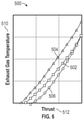
- FIG. 6 is a plot that graphically illustrates a relationship between exhaust gas temperature and thrust in a gas turbine engine, in accordance with an embodiment of the disclosure.
- FIG. 7 is a flow chart illustrating a method, in accordance with an embodiment of the disclosure.
- FIG. 1 schematically illustrates a gas turbine engine 20 .
- the gas turbine engine 20 is disclosed herein as a two-spool turbofan that generally incorporates a fan section 22 , a compressor section 24 , a combustor section 26 and a turbine section 28 .
- the fan section 22 drives air along a bypass flow path B in a bypass duct
- the compressor section 24 drives air along a core flow path C for compression and communication into the combustor section 26 then expansion through the turbine section 28 .
- the exemplary engine 20 generally includes a low speed spool 30 and a high speed spool 32 mounted for rotation about an engine central longitudinal axis A relative to an engine static structure 36 via several bearing systems 38 . It should be understood that various bearing systems 38 at various locations may alternatively or additionally be provided, and the location of bearing systems 38 may be varied as appropriate to the application.
- the low speed spool 30 generally includes an inner shaft 40 that interconnects a fan 42 , a low pressure compressor 44 and a low pressure turbine 46 .
- the inner shaft 40 is connected to the fan 42 through a speed change mechanism, which in exemplary gas turbine engine 20 is illustrated as a geared architecture 48 to drive the fan 42 at a lower speed than the low speed spool 30 .
- the high speed spool 32 includes an outer shaft 50 that interconnects a high pressure compressor 52 and high pressure turbine 54 .
- a combustor 56 is arranged in exemplary gas turbine 20 between the high pressure compressor 52 and the high pressure turbine 54 .
- An engine static structure 36 is arranged generally between the high pressure turbine 54 and the low pressure turbine 46 .
- the engine static structure 36 further supports bearing systems 38 in the turbine section 28 .
- the inner shaft 40 and the outer shaft 50 are concentric and rotate via bearing systems 38 about the engine central longitudinal axis A which is collinear with their longitudinal axes.
- stator vanes 45 in the low pressure compressor 44 and stator vanes 55 in the high pressure compressor 52 may be adjustable during operation of the gas turbine engine 20 to support various operating conditions. In other embodiments, the stator vanes 45 , 55 may be held in a fixed position.
- the turbines 46 , 54 rotationally drive the respective low speed spool 30 and high speed spool 32 in response to the expansion. It will be appreciated that each of the positions of the fan section 22 , compressor section 24 , combustor section 26 , turbine section 28 , and fan drive gear system 48 may be varied. For example, gear system 48 may be located aft of combustor section 26 or even aft of turbine section 28 , and fan section 22 may be positioned forward or aft of the location of gear system 48 .
- the engine 20 in one example is a high-bypass geared aircraft engine.
- the engine 20 bypass ratio is greater than about six (6), with an example embodiment being greater than about ten (10)
- the geared architecture 48 is an epicyclic gear train, such as a planetary gear system or other gear system, with a gear reduction ratio of greater than about 2.3
- the low pressure turbine 46 has a pressure ratio that is greater than about five.
- the engine 20 bypass ratio is greater than about ten (10:1)
- the fan diameter is significantly larger than that of the low pressure compressor 44
- the low pressure turbine 46 has a pressure ratio that is greater than about five 5:1.
- Low pressure turbine 46 pressure ratio is pressure measured prior to inlet of low pressure turbine 46 as related to the pressure at the outlet of the low pressure turbine 46 prior to an exhaust nozzle.
- the geared architecture 48 may be an epicycle gear train, such as a planetary gear system or other gear system, with a gear reduction ratio of greater than about 2.3:1. It should be understood, however, that the above parameters are only exemplary of one embodiment of a geared architecture engine and that the present disclosure is applicable to other gas turbine engines including direct drive turbofans.
- the fan section 22 of the engine 20 is designed for a particular flight condition—typically cruise at about 0.8 Mach and about 35,000 feet (10,688 meters).
- TSFC Thrust Specific Fuel Consumption
- Low fan pressure ratio is the pressure ratio across the fan blade alone, without a Fan Exit Guide Vane (“FEGV”) system.
- the low fan pressure ratio as disclosed herein according to one non-limiting embodiment is less than about 1.45.
- Low corrected fan tip speed is the actual fan tip speed in ft/sec divided by an industry standard temperature correction of [(Tram ° R)/(518.7° R)] ⁇ circumflex over ( ) ⁇ 0.5.
- the “Low corrected fan tip speed” as disclosed herein according to one non-limiting embodiment is less than about 1150 ft/second (350.5 m/sec).
- FIG. 1 illustrates one example of the gas turbine engine 20
- any number of spools, inclusion or omission of the gear system 48 , and/or other elements and subsystems are contemplated.
- rotor systems described herein can be used in a variety of applications and need not be limited to gas turbine engines for aircraft applications.
- rotor systems can be included in power generation systems, which may be ground-based as a fixed position or mobile system, and other such applications.
- FIG. 2 illustrates a hybrid electric propulsion system 100 (also referred to as hybrid gas turbine engine 100 ) including a gas turbine engine 120 operably coupled to an electrical power system 210 as part of a hybrid electric aircraft.
- One or more mechanical power transmissions 150 can be operably coupled between the gas turbine engine 120 and the electrical power system 210 .
- the gas turbine engine 120 can be an embodiment of the gas turbine engine 20 of FIG.
- the electrical power system 210 can include a first electric motor 212 A configured to augment rotational power of the low speed spool 30 and a second electric motor 212 B configured to augment rotational power of the high speed spool 32 . Although two electric motors 212 A, 212 B are depicted in FIG.
- the electrical power system 210 can also include a first electric generator 213 A configured to convert rotational power of the low speed spool 30 to electric power and a second electric generator 213 B configured to convert rotational power of the high speed spool 32 to electric power.
- a first electric generator 213 A configured to convert rotational power of the low speed spool 30 to electric power
- a second electric generator 213 B configured to convert rotational power of the high speed spool 32 to electric power.
- two electric generators 213 A, 213 B are depicted in FIG. 2 , it will be understood that there may be only a single electric generator (e.g., only electric generator 213 A) or additional electric generators (not depicted).
- one or more of the electric motors 212 A, 212 B can be configured as a motor or a generator depending upon an operational mode or system configuration, and thus one or more of the electric generators 213 A, 213 B may be omitted.
- the mechanical power transmission 150 A includes a gearbox operably coupled between the inner shaft 40 and a combination of the first electric motor 212 A and first electric generator 213 A.
- the mechanical power transmission 150 B can include a gearbox operably coupled between the outer shaft 50 and a combination of the second electric motor 212 B and second electric generator 213 B.
- the mechanical power transmission 150 A, 150 B can include a clutch or other interfacing element(s).
- the electrical power system 210 can also include motor drive electronics 214 A, 214 B operable to condition current to the electric motors 212 A, 212 B (e.g., DC-to-AC converters).
- the electrical power system 210 can also include rectifier electronics 215 A, 215 B operable to condition current from the electric generators 213 A, 213 B (e.g., AC-to-DC converters).
- the motor drive electronics 214 A, 214 B and rectifier electronics 215 A, 215 B can interface with an energy storage management system 216 that further interfaces with an energy storage system 218 .
- the energy storage management system 216 can be a bi-directional DC-DC converter that regulates voltages between energy storage system 218 and electronics 214 A, 214 B, 215 A, 215 B.
- the energy storage system 218 can include one or more energy storage devices, such as a battery, a super capacitor, an ultra capacitor, and the like.
- the energy storage management system 216 can facilitate various power transfers within the hybrid electric propulsion system 100 .
- power from the first electric generator 213 A can be transferred 211 to the second electric motor 212 B as a low speed spool 30 to high speed spool 32 power transfer.
- Other examples of power transfers may include a power transfer from the second electric generator 213 B to the first electric motor 212 A as a high speed spool 32 to low speed spool 30 power transfer.
- a power conditioning unit 220 and/or other components can be powered by the energy storage system 218 .
- the power conditioning unit 220 can distribute electric power to support actuation and other functions of the gas turbine engine 120 .
- the power conditioning unit 220 can power an integrated fuel control unit 222 to control fuel flow to the gas turbine engine 120 .
- the power conditioning unit 220 can power a plurality of actuators 224 , such as one or more of a low pressure compressor bleed valve actuator 226 , a low pressure compressor vane actuator 228 , a high pressure compressor vane actuator 230 , an active clearance control actuator 232 , and other such effectors.
- the low pressure compressor vane actuator 228 and/or the high pressure compressor vane actuator 230 can be omitted where active control of stator vanes 45 , 55 of FIG. 1 is not needed.
- any effectors that can change a state of the gas turbine engine 120 and/or the electrical power system 210 may be referred to as hybrid electric system control effectors 240 .
- Examples of the hybrid electric system control effectors 240 can include the electric motors 212 A, 212 B, electric generators 213 A, 213 B, integrated fuel control unit 222 , actuators 224 and/or other elements (not depicted).
- FIG. 3 is a schematic diagram of control signal paths 250 of the hybrid electric propulsion system 100 of FIG. 2 and is described with continued reference to FIGS. 1 and 2 .
- a controller 256 can interface with the motor drive electronics 214 A, 214 B, rectifier electronics 215 A, 215 B, energy storage management system 216 , integrated fuel control unit 222 , actuators 224 , and/or other components (not depicted) of the hybrid electric propulsion system 100 .
- the controller 256 can control and monitor for fault conditions of the gas turbine engine 120 and/or the electrical power system 210 .
- the controller 256 can be integrally formed or otherwise in communication with a full authority digital engine control (FADEC) of the gas turbine engine 120 .
- FADEC full authority digital engine control
- the controller 256 can include a processing system 260 , a memory system 262 , and an input/output interface 264 .
- the controller 256 can also include various operational controls, such as a power transfer control 266 that controls the hybrid electric system control effectors 240 as further described herein.
- the processing system 260 can include any type or combination of central processing unit (CPU), including one or more of: a microprocessor, a digital signal processor (DSP), a microcontroller, an application specific integrated circuit (ASIC), a field programmable gate array (FPGA), or the like.
- the memory system 262 can store data and instructions that are executed by the processing system 260 .
- the memory system 262 may include random access memory (RAM), read only memory (ROM), or other electronic, optical, magnetic, or any other computer readable medium onto which is stored data and algorithms in a non-transitory form.
- the input/output interface 264 is configured to collect sensor data from the one or more system sensors and interface with various components and subsystems, such as components of the motor drive electronics 214 A, 214 B, rectifier electronics 215 A, 215 B, energy storage management system 216 , integrated fuel control unit 222 , actuators 224 , and/or other components (not depicted) of the hybrid electric propulsion system 100 .
- the controller 256 provides a means for controlling the hybrid electric system control effectors 240 based on a power transfer control 266 that is dynamically updated during operation of the hybrid electric propulsion system 100 .
- the means for controlling the hybrid electric system control effectors 240 can be otherwise subdivided, distributed, or combined with other control elements.
- the power transfer control 266 can apply control laws and access/update models to determine how to control and transfer power to and from the hybrid electric system control effectors 240 .
- sensed and/or derived parameters related to speed, flow rate, pressure ratios, temperature, thrust, and the like can be used to establish operational schedules and transition limits to maintain efficient operation of the gas turbine engine 120 .
- the power transfer control 266 can control the hybrid electric system control effectors 240 to selectively transfer power between the low speed spool 30 and the high speed spool 32 of FIG. 1 .
- a compressor map or other control schedules can define relationships between multiple operating parameters of the gas turbine engine 120 .
- Schedules may seek to operate the compressor section 24 close to a stall line under certain operating conditions for efficient operation without resulting in a stall event.
- a stall line can be considered a stability limit line or a “not-to-exceed” operating line, with a stall margin providing a protective operating margin to avoid a stall event.
- a stall margin providing a protective operating margin to avoid a stall event.
- one approach is control the low pressure compressor bleed valve actuator 226 to selectively open engine bleeds; however, this may result in reduced operating efficiency if the compressed bleed air is dumped overboard or not otherwise used.
- the power transfer control 266 can control a power transfer between the first electric generator 213 A of the low speed spool 30 and the second electric motor 212 B of the high speed spool 32 to adjust a current operating condition of the gas turbine engine 120 based on a target operating condition for increasing stability in the compressor section 24 .
- the power transfer from the low speed spool 30 to the high speed spool 32 shifts the relationship between the speed of the low speed spool 30 and the high speed spool 32 while the power transfer is active. This results in the same speed (e.g., N 1 ) of the low speed spool 30 with a higher speed (N 2 ) of the high speed spool 32 based on the power transfer.
- N 1 speed of the low speed spool 30
- N 2 speed
- the power transfer control 266 can determine a low pressure compressor stability margin for combinations of engine properties, including vane angle, compressor corrected speed, a compressor pressure ratio, a compressor flow corrected at compressor inlet properties, and compressor flow corrected at compressor exit properties.
- a simplified model can be created and used in flight.
- a minimum compressor inlet flow corrected to compressor exit properties can be tabulated as a function of vane angle and compressor corrected speed such that low pressure compressor operability is satisfied with the combination or a higher corrected flow. In flight, any time the calculated compressor corrected flow falls below a tabulated limit, power transfer from the low speed spool 30 to the high speed spool 32 can be increased.
- Power transfer may be requested to be higher than the limit for other reasons, and a minimum power transfer can be used to maintain a minimum exit-corrected flow and satisfy compressor operability.
- compressor operability margin may be actively calculated in an onboard model and a minimum operability margin may be reached by increasing power transfer.
- plot 300 graphically illustrates a relationship between compressor pressure and compressor air flow in a gas turbine engine, such as the gas turbine engine 20 , 120 of FIGS. 1 and 2 .
- Line 302 illustrates an example relationship between a pressure ratio 310 of the low pressure compressor 44 and a low pressure compressor corrected air flow 312 under normal operating conditions without using the hybrid electric system control effectors 240 of FIGS. 2 and 3 .
- Line 304 illustrates an example relationship between the pressure ratio 310 of the low pressure compressor 44 and the low pressure compressor corrected air flow 312 using the low pressure compressor vane actuator 228 and/or the high pressure compressor vane actuator 230 to adjust vane angles of the stator vanes 45 , 55 to improve low pressure compressor stall margin.
- Line 306 illustrates an example relationship between the pressure ratio 310 of the low pressure compressor 44 and the low pressure compressor corrected air flow 312 using a power transfer between the first electric generator 213 A of the low speed spool 30 and the second electric motor 212 B of the high speed spool 32 to adjust a current operating condition of the gas turbine engine 120 to improve low pressure compressor stall margin.
- the lines 302 and 304 have higher values of the pressure ratio 310 of the low pressure compressor 44 as the low pressure compressor corrected air flow 312 increases, resulting in being closer to a stall event than line 306 .
- plot 400 graphically illustrates a relationship between compressor air flow and compressor speed in a gas turbine engine, such as the gas turbine engine 20 , 120 of FIGS. 1 and 2 .
- Line 402 illustrates an example relationship between a low pressure compressor air flow 410 and a speed 412 of the low pressure compressor 44 under normal operating conditions without using the hybrid electric system control effectors 240 of FIGS. 2 and 3 .
- the low pressure compressor air flow 410 may differ from the low pressure compressor corrected air flow 312 of FIG. 4 , for instance, using a different but related pressure associated with portions of the compressor section 24 of FIG. 1 .
- the speed 412 may be corrected or normalized value of N 1 speed.
- Line 404 illustrates an example relationship between the low pressure compressor air flow 410 and the speed 412 of the low pressure compressor 44 using the low pressure compressor vane actuator 228 and/or the high pressure compressor vane actuator 230 to adjust vane angles of the stator vanes 45 , 55 to improve low pressure compressor stall margin.
- Line 406 illustrates an example relationship between the low pressure compressor air flow 410 and the speed 412 of the low pressure compressor 44 using a power transfer between the first electric generator 213 A of the low speed spool 30 and the second electric motor 212 B of the high speed spool 32 to adjust a current operating condition of the gas turbine engine 120 to improve low pressure compressor stall margin.
- the lines 402 and 404 have lower values of the low pressure compressor air flow 410 as the speed 412 of the low pressure compressor 44 increases. The air higher flow to speed relationship can provide a wider stall margin for the low pressure compressor 44 .
- plot 500 graphically illustrates a relationship between exhaust gas temperature 510 and thrust 512 in a gas turbine engine at medium to high power, such as the gas turbine engine 20 , 120 of FIGS. 1 and 2 .
- Line 502 illustrates an example relationship between exhaust gas temperature 510 and thrust 512 under normal operating conditions without using the hybrid electric system control effectors 240 of FIGS. 2 and 3 .
- Line 504 illustrates an example relationship between exhaust gas temperature 510 and thrust 512 when improving low pressure compressor stall margin using the low pressure compressor vane actuator 228 and/or the high pressure compressor vane actuator 230 to adjust vane angles of the stator vanes 45 , 55 .
- Line 506 illustrates an example relationship between exhaust gas temperature 510 and thrust 512 using a power transfer between the first electric generator 213 A of the low speed spool 30 and the second electric motor 212 B of the high speed spool 32 to adjust a current operating condition of the gas turbine engine 120 to improve low pressure compressor stall margin.
- line 504 indicates a larger value of exhaust gas temperature 510 than line 502
- line 506 has a lower value of exhaust gas temperature 510 than both of lines 502 , 504 .
- line 506 has the additional benefit of reducing hot section temperatures while the conventional means of managing low pressure compressor margin (line 504 ) is detrimental to hot section temperatures and to engine life.
- FIG. 7 is a flow chart illustrating a method 600 for compressor operability control for a hybrid electric propulsion system, in accordance with an embodiment.
- the method 600 may be performed, for example, by the hybrid electric propulsion system 100 of FIG. 2 .
- the method 600 is described primarily with respect to the hybrid electric propulsion system 100 of FIG. 2 ; however, it will be understood that the method 600 can be performed on other configurations (not depicted).
- Method 600 pertains to the controller 256 executing embedded code for the power transfer control 266 to control components of the hybrid electric system control effectors 240 .
- controller 256 can determine a target operating condition of a low pressure compressor 44 to achieve a compressor stability margin in a gas turbine engine 120 including a low speed spool 30 and a high speed spool 32 , where the low speed spool 30 includes the low pressure compressor 44 and a low pressure turbine 46 , and the high speed spool 32 includes a high pressure compressor 52 and a high pressure turbine 54 .
- the target operating condition of the low pressure compressor 44 can be determined by the controller 256 with respect to one or more engine properties that enable an estimate of stability of the low pressure compressor.
- the one or more engine properties can include one or more of: a vane angle, a compressor corrected speed, a compressor pressure ratio, a compressor flow corrected at compressor inlet properties, and a compressor flow corrected at compressor exit properties.
- the one or more engine properties can be used as a proxy for stability in making stability estimates by the controller 256 .
- the target operating condition can be based on a target pressure ratio 310 of the low pressure compressor 44 associated with a low pressure compressor corrected air flow 312 . Further, the target operating condition can include a target pressure ratio 310 associated with a combination of a low pressure compressor corrected air flow and a vane angle of the stator vanes 45 , 55 .
- the controller 256 can determine a current operating condition of the low pressure compressor 44 .
- the current operating condition can include a current pressure ratio of the low pressure compressor 44 , such as a ratio relating the input pressure at the low pressure compressor 44 to a midpoint between the low pressure compressor 44 and the high pressure compressor 52 or an output of the high pressure compressor 52 .
- the current operating condition can also include a current corrected flow.
- the controller 256 can control a power transfer between an electric generator 213 A of the low speed spool 30 and an electric motor 212 B of the high speed spool 32 to adjust the current operating condition of the low pressure compressor 44 based on the target operating condition.
- the low pressure compressor corrected air flow 312 and the current pressure ratio can be adjusted based on the target pressure ratio (e.g., control to correspond with line 306 ).
- the controller 256 can adjust the target operating condition.
- the target operating condition can be adjusted based on a state change or parameter that modifies compressor performance.
- the target operating condition can be adjusted based on a rate of change in speed 412 of the low pressure compressor 44 .
- the controller 256 can be further configured to adjust the target pressure ratio based on a rate of change in speed 412 of the low pressure compressor 44 . Rate changes can be used for predictive controls as one or more additional state parameters.
- the method 600 can loop back to block 604 and continue making adjustments and updating the target operating condition as the gas turbine engine 120 changes operating conditions with respect to speed 412 , thrust 512 , or other such parameters.
- an exhaust gas temperature 510 of the gas turbine engine 120 (as well as other hot section temperatures) can be reduced based on transferring power between the electric generator 213 A of the low speed spool 44 and the electric motor 212 B of the high speed spool 32 while maintaining a substantially constant thrust 512 .
- various power transfer options can be implemented to assist in control operations. For instance, power from the electric generator 213 A can be transferred to an energy storage system 218 . Power from the energy storage system 218 can be transferred to the electric motor 212 B. Transferring of power from the electric generator 213 A to the electric motor 212 B of the high speed spool 32 can be performed absent a change in output of a low pressure compressor vane actuator 228 of the gas turbine engine 120 .
- one or more stages of variable vanes 45 , 55 can be removed where compressor operability control can be fully managed by power transfers using one or more of the electric motors 212 A, 212 B and electric generators 213 A, 213 B. Additionally, rotational power can be transferred between the low speed spool 30 and either the electric generator 213 A or a low speed spool electric motor 212 A through a first mechanical power transmission 150 A. Further, rotational power can be transferred between the high speed spool 32 and either the electric motor 212 B or a high speed spool electric generator 213 B through a second mechanical power transmission 150 B.
Landscapes
- Engineering & Computer Science (AREA)
- Mechanical Engineering (AREA)
- General Engineering & Computer Science (AREA)
- Chemical & Material Sciences (AREA)
- Combustion & Propulsion (AREA)
- Aviation & Aerospace Engineering (AREA)
- Control Of Positive-Displacement Air Blowers (AREA)
Abstract
Description
Claims (20)
Priority Applications (2)
| Application Number | Priority Date | Filing Date | Title |
|---|---|---|---|
| US16/511,276 US11261751B2 (en) | 2019-07-15 | 2019-07-15 | Compressor operability control for hybrid electric propulsion |
| EP20186056.6A EP3767090B2 (en) | 2019-07-15 | 2020-07-15 | Compressor operability control for hybrid electric propulsion |
Applications Claiming Priority (1)
| Application Number | Priority Date | Filing Date | Title |
|---|---|---|---|
| US16/511,276 US11261751B2 (en) | 2019-07-15 | 2019-07-15 | Compressor operability control for hybrid electric propulsion |
Publications (2)
| Publication Number | Publication Date |
|---|---|
| US20210017878A1 US20210017878A1 (en) | 2021-01-21 |
| US11261751B2 true US11261751B2 (en) | 2022-03-01 |
Family
ID=71620357
Family Applications (1)
| Application Number | Title | Priority Date | Filing Date |
|---|---|---|---|
| US16/511,276 Active 2039-12-23 US11261751B2 (en) | 2019-07-15 | 2019-07-15 | Compressor operability control for hybrid electric propulsion |
Country Status (2)
| Country | Link |
|---|---|
| US (1) | US11261751B2 (en) |
| EP (1) | EP3767090B2 (en) |
Cited By (1)
| Publication number | Priority date | Publication date | Assignee | Title |
|---|---|---|---|---|
| US11649763B1 (en) | 2022-06-23 | 2023-05-16 | Raytheon Technologies Corporation | Rating control architecture and method for hybrid electric engine |
Families Citing this family (3)
| Publication number | Priority date | Publication date | Assignee | Title |
|---|---|---|---|---|
| US11186378B2 (en) | 2019-03-29 | 2021-11-30 | Pratt & Whitney Canada Corp. | Hybrid aircraft propulsion power plants |
| GB201912322D0 (en) * | 2019-08-28 | 2019-10-09 | Rolls Royce Plc | Gas turbine engine flow control |
| US12252993B1 (en) * | 2021-11-05 | 2025-03-18 | United States Of America As Represented By The Administrator Of Nasa | Fluid actuator operability improvement with fast energy storage |
Citations (11)
| Publication number | Priority date | Publication date | Assignee | Title |
|---|---|---|---|---|
| EP1712761A2 (en) | 2005-04-08 | 2006-10-18 | United Technologies Corporation | Electrically coupled two-shaft gas turbine engine |
| WO2008045058A1 (en) * | 2006-10-12 | 2008-04-17 | United Technologies Corporation | Operational line management of low pressure compressor in a turbofan engine |
| US7788898B2 (en) | 2006-12-06 | 2010-09-07 | General Electric Company | Variable coupling of turbofan engine spools via open differential gear set or simple planetary gear set for improved power extraction and engine operability, with torque coupling for added flexibility |
| US20100251726A1 (en) | 2007-01-17 | 2010-10-07 | United Technologies Corporation | Turbine engine transient power extraction system and method |
| US8459038B1 (en) | 2012-02-09 | 2013-06-11 | Williams International Co., L.L.C. | Two-spool turboshaft engine control system and method |
| US20130236296A1 (en) | 2012-03-09 | 2013-09-12 | Pratt & Whitney | Low Pressure Compressor Variable Vane Control for Two-Spool Turbofan or Turboprop Engine |
| EP3412575A1 (en) | 2017-06-08 | 2018-12-12 | General Electric Company | Hybrid-electric propulsion system for an aircraft |
| EP3421760A1 (en) | 2017-06-26 | 2019-01-02 | General Electric Company | Propulsion system for an aircraft |
| EP3421372A1 (en) | 2017-06-30 | 2019-01-02 | General Electric Company | Propulsion system for an aircraft |
| EP3480433A1 (en) | 2017-11-06 | 2019-05-08 | Rolls-Royce plc | Multi-shaft gas turbine engine |
| EP3623203A1 (en) | 2018-08-17 | 2020-03-18 | United Technologies Corporation | Hybrid electric aircraft battery charging |
Family Cites Families (4)
| Publication number | Priority date | Publication date | Assignee | Title |
|---|---|---|---|---|
| US7762084B2 (en) | 2004-11-12 | 2010-07-27 | Rolls-Royce Canada, Ltd. | System and method for controlling the working line position in a gas turbine engine compressor |
| FR3024755B1 (en) | 2014-08-08 | 2019-06-21 | Safran Aircraft Engines | HYBRIDIZING THE COMPRESSORS OF A TURBOJET ENGINE |
| EP3246525B1 (en) | 2016-05-18 | 2020-07-08 | Rolls-Royce Corporation | Gas turbine engines with flutter control |
| US11022042B2 (en) | 2016-08-29 | 2021-06-01 | Rolls-Royce North American Technologies Inc. | Aircraft having a gas turbine generator with power assist |
-
2019
- 2019-07-15 US US16/511,276 patent/US11261751B2/en active Active
-
2020
- 2020-07-15 EP EP20186056.6A patent/EP3767090B2/en active Active
Patent Citations (12)
| Publication number | Priority date | Publication date | Assignee | Title |
|---|---|---|---|---|
| EP1712761A2 (en) | 2005-04-08 | 2006-10-18 | United Technologies Corporation | Electrically coupled two-shaft gas turbine engine |
| WO2008045058A1 (en) * | 2006-10-12 | 2008-04-17 | United Technologies Corporation | Operational line management of low pressure compressor in a turbofan engine |
| US7788898B2 (en) | 2006-12-06 | 2010-09-07 | General Electric Company | Variable coupling of turbofan engine spools via open differential gear set or simple planetary gear set for improved power extraction and engine operability, with torque coupling for added flexibility |
| US20100251726A1 (en) | 2007-01-17 | 2010-10-07 | United Technologies Corporation | Turbine engine transient power extraction system and method |
| US8459038B1 (en) | 2012-02-09 | 2013-06-11 | Williams International Co., L.L.C. | Two-spool turboshaft engine control system and method |
| US20130236296A1 (en) | 2012-03-09 | 2013-09-12 | Pratt & Whitney | Low Pressure Compressor Variable Vane Control for Two-Spool Turbofan or Turboprop Engine |
| EP3412575A1 (en) | 2017-06-08 | 2018-12-12 | General Electric Company | Hybrid-electric propulsion system for an aircraft |
| US20180354631A1 (en) * | 2017-06-08 | 2018-12-13 | General Electric Company | Hybrid-electric propulsion system for an aircraft |
| EP3421760A1 (en) | 2017-06-26 | 2019-01-02 | General Electric Company | Propulsion system for an aircraft |
| EP3421372A1 (en) | 2017-06-30 | 2019-01-02 | General Electric Company | Propulsion system for an aircraft |
| EP3480433A1 (en) | 2017-11-06 | 2019-05-08 | Rolls-Royce plc | Multi-shaft gas turbine engine |
| EP3623203A1 (en) | 2018-08-17 | 2020-03-18 | United Technologies Corporation | Hybrid electric aircraft battery charging |
Non-Patent Citations (1)
| Title |
|---|
| EP Application No. 20186056.6 Extended EP Search Report dated Dec. 8, 2020, 7 pages. |
Cited By (1)
| Publication number | Priority date | Publication date | Assignee | Title |
|---|---|---|---|---|
| US11649763B1 (en) | 2022-06-23 | 2023-05-16 | Raytheon Technologies Corporation | Rating control architecture and method for hybrid electric engine |
Also Published As
| Publication number | Publication date |
|---|---|
| EP3767090B2 (en) | 2025-11-26 |
| US20210017878A1 (en) | 2021-01-21 |
| EP3767090B1 (en) | 2023-02-15 |
| EP3767090A1 (en) | 2021-01-20 |
Similar Documents
| Publication | Publication Date | Title |
|---|---|---|
| US11821369B2 (en) | Electric power assist for in-flight engine re-start | |
| US11473496B2 (en) | Transient operation control of a hybrid gas turbine engine | |
| US12092038B2 (en) | Rotor dynamics accommodation using electrical power assist | |
| EP3767090B1 (en) | Compressor operability control for hybrid electric propulsion | |
| US12140083B2 (en) | Adaptive model predictive control for hybrid electric propulsion | |
| US12359616B2 (en) | Oil circulation system for hybrid electric engine | |
| US11821372B2 (en) | Hybrid electric engine with electric tip clearance mechanism | |
| EP3767092B1 (en) | Modulated combustor bypass for hybrid idle | |
| US11773743B2 (en) | Model-based rotor speed keep out zone control | |
| US20220397067A1 (en) | Hybrid electric idle transition for aircraft | |
| US11557995B2 (en) | Aircraft engine power-assist start stability control | |
| EP4112909A1 (en) | Hybrid electric variable area turbine | |
| US11459946B2 (en) | Gas turbine engine spool coupling | |
| US11415065B2 (en) | Material fatigue improvement for hybrid propulsion systems | |
| US11649763B1 (en) | Rating control architecture and method for hybrid electric engine |
Legal Events
| Date | Code | Title | Description |
|---|---|---|---|
| AS | Assignment |
Owner name: UNITED TECHNOLOGIES CORPORATION, CONNECTICUT Free format text: ASSIGNMENT OF ASSIGNORS INTEREST;ASSIGNORS:GOLFIN, DAVID A.;TERWILLIGER, NEIL;REEL/FRAME:049751/0832 Effective date: 20190711 |
|
| FEPP | Fee payment procedure |
Free format text: ENTITY STATUS SET TO UNDISCOUNTED (ORIGINAL EVENT CODE: BIG.); ENTITY STATUS OF PATENT OWNER: LARGE ENTITY |
|
| STPP | Information on status: patent application and granting procedure in general |
Free format text: NON FINAL ACTION MAILED |
|
| STPP | Information on status: patent application and granting procedure in general |
Free format text: RESPONSE TO NON-FINAL OFFICE ACTION ENTERED AND FORWARDED TO EXAMINER |
|
| STPP | Information on status: patent application and granting procedure in general |
Free format text: FINAL REJECTION MAILED |
|
| AS | Assignment |
Owner name: RAYTHEON TECHNOLOGIES CORPORATION, CONNECTICUT Free format text: CHANGE OF NAME;ASSIGNOR:UNITED TECHNOLOGIES CORPORATION;REEL/FRAME:057190/0719 Effective date: 20200403 |
|
| AS | Assignment |
Owner name: RAYTHEON TECHNOLOGIES CORPORATION, CONNECTICUT Free format text: CORRECTIVE ASSIGNMENT TO CORRECT THE SPELLING ON THE ADDRESS 10 FARM SPRINGD ROAD FARMINGTONCONNECTICUT 06032 PREVIOUSLY RECORDED ON REEL 057190 FRAME 0719. ASSIGNOR(S) HEREBY CONFIRMS THE CORRECT SPELLING OF THE ADDRESS 10 FARM SPRINGS ROAD FARMINGTON CONNECTICUT 06032;ASSIGNOR:UNITED TECHNOLOGIES CORPORATION;REEL/FRAME:057226/0390 Effective date: 20200403 |
|
| STPP | Information on status: patent application and granting procedure in general |
Free format text: RESPONSE AFTER FINAL ACTION FORWARDED TO EXAMINER |
|
| STPP | Information on status: patent application and granting procedure in general |
Free format text: ADVISORY ACTION MAILED |
|
| STPP | Information on status: patent application and granting procedure in general |
Free format text: DOCKETED NEW CASE - READY FOR EXAMINATION |
|
| STPP | Information on status: patent application and granting procedure in general |
Free format text: NOTICE OF ALLOWANCE MAILED -- APPLICATION RECEIVED IN OFFICE OF PUBLICATIONS |
|
| STCF | Information on status: patent grant |
Free format text: PATENTED CASE |
|
| AS | Assignment |
Owner name: RTX CORPORATION, CONNECTICUT Free format text: CHANGE OF NAME;ASSIGNOR:RAYTHEON TECHNOLOGIES CORPORATION;REEL/FRAME:064714/0001 Effective date: 20230714 |
|
| MAFP | Maintenance fee payment |
Free format text: PAYMENT OF MAINTENANCE FEE, 4TH YEAR, LARGE ENTITY (ORIGINAL EVENT CODE: M1551); ENTITY STATUS OF PATENT OWNER: LARGE ENTITY Year of fee payment: 4 |