US11260643B2 - Laminating apparatus, and film cassette and film shaft used therein - Google Patents
Laminating apparatus, and film cassette and film shaft used therein Download PDFInfo
- Publication number
- US11260643B2 US11260643B2 US16/304,439 US201716304439A US11260643B2 US 11260643 B2 US11260643 B2 US 11260643B2 US 201716304439 A US201716304439 A US 201716304439A US 11260643 B2 US11260643 B2 US 11260643B2
- Authority
- US
- United States
- Prior art keywords
- film
- cassette
- sheet
- main body
- shaft
- Prior art date
- Legal status (The legal status is an assumption and is not a legal conclusion. Google has not performed a legal analysis and makes no representation as to the accuracy of the status listed.)
- Active, expires
Links
Images


Classifications
-
- B—PERFORMING OPERATIONS; TRANSPORTING
- B32—LAYERED PRODUCTS
- B32B—LAYERED PRODUCTS, i.e. PRODUCTS BUILT-UP OF STRATA OF FLAT OR NON-FLAT, e.g. CELLULAR OR HONEYCOMB, FORM
- B32B37/00—Methods or apparatus for laminating, e.g. by curing or by ultrasonic bonding
- B32B37/0046—Methods or apparatus for laminating, e.g. by curing or by ultrasonic bonding characterised by constructional aspects of the apparatus
- B32B37/0053—Constructional details of laminating machines comprising rollers; Constructional features of the rollers
-
- B—PERFORMING OPERATIONS; TRANSPORTING
- B32—LAYERED PRODUCTS
- B32B—LAYERED PRODUCTS, i.e. PRODUCTS BUILT-UP OF STRATA OF FLAT OR NON-FLAT, e.g. CELLULAR OR HONEYCOMB, FORM
- B32B41/00—Arrangements for controlling or monitoring lamination processes; Safety arrangements
-
- B—PERFORMING OPERATIONS; TRANSPORTING
- B32—LAYERED PRODUCTS
- B32B—LAYERED PRODUCTS, i.e. PRODUCTS BUILT-UP OF STRATA OF FLAT OR NON-FLAT, e.g. CELLULAR OR HONEYCOMB, FORM
- B32B37/00—Methods or apparatus for laminating, e.g. by curing or by ultrasonic bonding
- B32B37/14—Methods or apparatus for laminating, e.g. by curing or by ultrasonic bonding characterised by the properties of the layers
- B32B37/16—Methods or apparatus for laminating, e.g. by curing or by ultrasonic bonding characterised by the properties of the layers with all layers existing as coherent layers before laminating
- B32B37/22—Methods or apparatus for laminating, e.g. by curing or by ultrasonic bonding characterised by the properties of the layers with all layers existing as coherent layers before laminating involving the assembly of both discrete and continuous layers
- B32B37/223—One or more of the layers being plastic
- B32B37/226—Laminating sheets, panels or inserts between two continuous plastic layers
-
- B—PERFORMING OPERATIONS; TRANSPORTING
- B29—WORKING OF PLASTICS; WORKING OF SUBSTANCES IN A PLASTIC STATE IN GENERAL
- B29C—SHAPING OR JOINING OF PLASTICS; SHAPING OF MATERIAL IN A PLASTIC STATE, NOT OTHERWISE PROVIDED FOR; AFTER-TREATMENT OF THE SHAPED PRODUCTS, e.g. REPAIRING
- B29C63/00—Lining or sheathing, i.e. applying preformed layers or sheathings of plastics; Apparatus therefor
- B29C63/02—Lining or sheathing, i.e. applying preformed layers or sheathings of plastics; Apparatus therefor using sheet or web-like material
-
- B—PERFORMING OPERATIONS; TRANSPORTING
- B29—WORKING OF PLASTICS; WORKING OF SUBSTANCES IN A PLASTIC STATE IN GENERAL
- B29C—SHAPING OR JOINING OF PLASTICS; SHAPING OF MATERIAL IN A PLASTIC STATE, NOT OTHERWISE PROVIDED FOR; AFTER-TREATMENT OF THE SHAPED PRODUCTS, e.g. REPAIRING
- B29C65/00—Joining or sealing of preformed parts, e.g. welding of plastics materials; Apparatus therefor
- B29C65/02—Joining or sealing of preformed parts, e.g. welding of plastics materials; Apparatus therefor by heating, with or without pressure
-
- B—PERFORMING OPERATIONS; TRANSPORTING
- B29—WORKING OF PLASTICS; WORKING OF SUBSTANCES IN A PLASTIC STATE IN GENERAL
- B29C—SHAPING OR JOINING OF PLASTICS; SHAPING OF MATERIAL IN A PLASTIC STATE, NOT OTHERWISE PROVIDED FOR; AFTER-TREATMENT OF THE SHAPED PRODUCTS, e.g. REPAIRING
- B29C65/00—Joining or sealing of preformed parts, e.g. welding of plastics materials; Apparatus therefor
- B29C65/74—Joining or sealing of preformed parts, e.g. welding of plastics materials; Apparatus therefor by welding and severing, or by joining and severing, the severing being performed in the area to be joined, next to the area to be joined, in the joint area or next to the joint area
-
- B—PERFORMING OPERATIONS; TRANSPORTING
- B29—WORKING OF PLASTICS; WORKING OF SUBSTANCES IN A PLASTIC STATE IN GENERAL
- B29C—SHAPING OR JOINING OF PLASTICS; SHAPING OF MATERIAL IN A PLASTIC STATE, NOT OTHERWISE PROVIDED FOR; AFTER-TREATMENT OF THE SHAPED PRODUCTS, e.g. REPAIRING
- B29C66/00—General aspects of processes or apparatus for joining preformed parts
- B29C66/40—General aspects of joining substantially flat articles, e.g. plates, sheets or web-like materials; Making flat seams in tubular or hollow articles; Joining single elements to substantially flat surfaces
- B29C66/47—Joining single elements to sheets, plates or other substantially flat surfaces
- B29C66/472—Joining single elements to sheets, plates or other substantially flat surfaces said single elements being substantially flat
-
- B—PERFORMING OPERATIONS; TRANSPORTING
- B29—WORKING OF PLASTICS; WORKING OF SUBSTANCES IN A PLASTIC STATE IN GENERAL
- B29C—SHAPING OR JOINING OF PLASTICS; SHAPING OF MATERIAL IN A PLASTIC STATE, NOT OTHERWISE PROVIDED FOR; AFTER-TREATMENT OF THE SHAPED PRODUCTS, e.g. REPAIRING
- B29C66/00—General aspects of processes or apparatus for joining preformed parts
- B29C66/80—General aspects of machine operations or constructions and parts thereof
- B29C66/83—General aspects of machine operations or constructions and parts thereof characterised by the movement of the joining or pressing tools
- B29C66/834—General aspects of machine operations or constructions and parts thereof characterised by the movement of the joining or pressing tools moving with the parts to be joined
- B29C66/8341—Roller, cylinder or drum types; Band or belt types; Ball types
- B29C66/83411—Roller, cylinder or drum types
- B29C66/83413—Roller, cylinder or drum types cooperating rollers, cylinders or drums
-
- B—PERFORMING OPERATIONS; TRANSPORTING
- B32—LAYERED PRODUCTS
- B32B—LAYERED PRODUCTS, i.e. PRODUCTS BUILT-UP OF STRATA OF FLAT OR NON-FLAT, e.g. CELLULAR OR HONEYCOMB, FORM
- B32B27/00—Layered products comprising a layer of synthetic resin
- B32B27/06—Layered products comprising a layer of synthetic resin as the main or only constituent of a layer, which is next to another layer of the same or of a different material
- B32B27/10—Layered products comprising a layer of synthetic resin as the main or only constituent of a layer, which is next to another layer of the same or of a different material of paper or cardboard
-
- B—PERFORMING OPERATIONS; TRANSPORTING
- B32—LAYERED PRODUCTS
- B32B—LAYERED PRODUCTS, i.e. PRODUCTS BUILT-UP OF STRATA OF FLAT OR NON-FLAT, e.g. CELLULAR OR HONEYCOMB, FORM
- B32B37/00—Methods or apparatus for laminating, e.g. by curing or by ultrasonic bonding
- B32B37/06—Methods or apparatus for laminating, e.g. by curing or by ultrasonic bonding characterised by the heating method
-
- B—PERFORMING OPERATIONS; TRANSPORTING
- B32—LAYERED PRODUCTS
- B32B—LAYERED PRODUCTS, i.e. PRODUCTS BUILT-UP OF STRATA OF FLAT OR NON-FLAT, e.g. CELLULAR OR HONEYCOMB, FORM
- B32B37/00—Methods or apparatus for laminating, e.g. by curing or by ultrasonic bonding
- B32B37/10—Methods or apparatus for laminating, e.g. by curing or by ultrasonic bonding characterised by the pressing technique, e.g. using action of vacuum or fluid pressure
-
- B—PERFORMING OPERATIONS; TRANSPORTING
- B32—LAYERED PRODUCTS
- B32B—LAYERED PRODUCTS, i.e. PRODUCTS BUILT-UP OF STRATA OF FLAT OR NON-FLAT, e.g. CELLULAR OR HONEYCOMB, FORM
- B32B38/00—Ancillary operations in connection with laminating processes
- B32B38/0004—Cutting, tearing or severing, e.g. bursting; Cutter details
-
- B—PERFORMING OPERATIONS; TRANSPORTING
- B32—LAYERED PRODUCTS
- B32B—LAYERED PRODUCTS, i.e. PRODUCTS BUILT-UP OF STRATA OF FLAT OR NON-FLAT, e.g. CELLULAR OR HONEYCOMB, FORM
- B32B38/00—Ancillary operations in connection with laminating processes
- B32B38/18—Handling of layers or the laminate
-
- B—PERFORMING OPERATIONS; TRANSPORTING
- B65—CONVEYING; PACKING; STORING; HANDLING THIN OR FILAMENTARY MATERIAL
- B65H—HANDLING THIN OR FILAMENTARY MATERIAL, e.g. SHEETS, WEBS, CABLES
- B65H75/00—Storing webs, tapes, or filamentary material, e.g. on reels
- B65H75/02—Cores, formers, supports, or holders for coiled, wound, or folded material, e.g. reels, spindles, bobbins, cop tubes, cans, mandrels or chucks
- B65H75/04—Kinds or types
- B65H75/08—Kinds or types of circular or polygonal cross-section
- B65H75/10—Kinds or types of circular or polygonal cross-section without flanges, e.g. cop tubes
-
- B—PERFORMING OPERATIONS; TRANSPORTING
- B65—CONVEYING; PACKING; STORING; HANDLING THIN OR FILAMENTARY MATERIAL
- B65H—HANDLING THIN OR FILAMENTARY MATERIAL, e.g. SHEETS, WEBS, CABLES
- B65H75/00—Storing webs, tapes, or filamentary material, e.g. on reels
- B65H75/02—Cores, formers, supports, or holders for coiled, wound, or folded material, e.g. reels, spindles, bobbins, cop tubes, cans, mandrels or chucks
- B65H75/18—Constructional details
- B65H75/30—Arrangements to facilitate driving or braking
-
- B—PERFORMING OPERATIONS; TRANSPORTING
- B32—LAYERED PRODUCTS
- B32B—LAYERED PRODUCTS, i.e. PRODUCTS BUILT-UP OF STRATA OF FLAT OR NON-FLAT, e.g. CELLULAR OR HONEYCOMB, FORM
- B32B2429/00—Carriers for sound or information
-
- B—PERFORMING OPERATIONS; TRANSPORTING
- B32—LAYERED PRODUCTS
- B32B—LAYERED PRODUCTS, i.e. PRODUCTS BUILT-UP OF STRATA OF FLAT OR NON-FLAT, e.g. CELLULAR OR HONEYCOMB, FORM
- B32B41/00—Arrangements for controlling or monitoring lamination processes; Safety arrangements
- B32B41/02—Safety arrangements
-
- B—PERFORMING OPERATIONS; TRANSPORTING
- B65—CONVEYING; PACKING; STORING; HANDLING THIN OR FILAMENTARY MATERIAL
- B65H—HANDLING THIN OR FILAMENTARY MATERIAL, e.g. SHEETS, WEBS, CABLES
- B65H2301/00—Handling processes for sheets or webs
- B65H2301/50—Auxiliary process performed during handling process
- B65H2301/51—Modifying a characteristic of handled material
- B65H2301/511—Processing surface of handled material upon transport or guiding thereof, e.g. cleaning
- B65H2301/5114—Processing surface of handled material upon transport or guiding thereof, e.g. cleaning coating
Definitions
- the present invention relates to a laminating apparatus used for a laminating process for a purpose of improving durability and water resistance of various types of paper. More particularly, the present invention relates to a laminating apparatus that enables laminate films to be loaded easily by means of a cassette system, and to a film cassette and a film shaft used therein.
- a laminating process is carried out by sandwiching both sides of paper with sheets of synthetic resin films.
- a laminating apparatus which enables the laminating process to be performed automatically has been conventionally used.
- a laminating apparatus in which a mechanism for press-bonding a sheet or film for lamination by sandwiching the sheet or film, and conveying and cutting the sheet or film can be divided into upper and lower units that sandwich a lamination target object, to thereby facilitate setting of a film and the like (tor example, see Patent Literature 3).
- Patent Literature 1 JP 2001-79940 A
- Patent Literature 2 JP 2006-015516 A
- Patent Literature 3 JP 2004-243659 A
- Patent Literature 1 when a film as described in Patent Literature 1 is stored in a cassette, it is easy to install the cassette. However, it is complicated to successfully guide the film from the cassette into the apparatus and to set the film into the apparatus thereafter. In particular, in order to wind a film at a sufficient angle around a roller for a laminating process as described in Patent Literature 2, a movable mechanism for a guide roller is required. This makes the structure complicated, and causes a cost increase. Further, it is necessary to move the guide roller by a lever or the like. Therefore, there is a problem that if a position change of the guide roller is forgotten, a defective product may be generated.
- the laminating process it is necessary to change a condition of the laminating process according to a thickness and a type of a film to be used. As such, even though the type of the film is changed by a simple operation such as changing of a film cassette, if a process is performed without setting a lamination condition for the film, there is a problem that the laminating process fails.
- An object of the present invention is to solve the problems as described above, and to provide a laminating apparatus in which a film is replaced using a cassette system and provide related components thereof, the laminating apparatus having a simple structure and enabling a film to be loaded reliably and easily, solving a problem of sufficient winding of a film around a pressing roller and a problem of a film feed brake as described above, realizing easy installation of a film without damaging components, and preventing a failure in a laminating process due to erroneous settings or erroneous recognition.
- a first aspect of the invention is a laminating apparatus including a sheet feed mechanism unit configured to convey a sheet to be laminated into an apparatus main body, a film cassette in which a pair of films for lamination is accommodated, the film cassette being detachable from the apparatus main body, and a press-bonding mechanism unit configured to perform a laminating process through thermal press bonding while sandwiching the sheet with the pair of films delivered from the cassette in the apparatus main body.
- the apparatus main body includes an upper unit of an openable and closable type, and the upper unit is provided with one pressing roller of a pair of pressing rollers for press-bonding in the press-bonding mechanism unit, and an upper member of another mechanism for performing a process in a state where upper and lower sides of the sheet is sandwiched between the pair of films.
- the fourth aspect of the invention employs a configuration that in the laminating apparatus according to the third aspect, each of the pair of idle rollers is pivotally supported by end portions of a pair of roller arms, and when the film cassette is installed in the apparatus main body, one ends of the roller arms are projectable and retractable from an inside of the film cassette into the apparatus main body.
- the fifth aspect of the invention employs a configuration that in the laminating apparatus according to the fourth aspect, the pair of idle rollers protrudes according to an operation of closing the upper unit, and retracts according to an operation of opening the upper unit.
- the seventh aspect of the invention employs a configuration that the laminating apparatus according to any one of the first to sixth aspects further includes a rotary cutter unit provided behind the press-bonding mechanism unit, the rotary cutter unit being configured to sandwich a sheet, to which the laminating process is applied, between a fixed blade and a rotary blade and cut the sheet in a width direction, and a mechanism configured to, when the rotary blade is located at a rotary position at which the rotary blade abuts against the fixed blade at a time of closing a cover of an openable and closable type, separate positions of the rotary blade and the fixed blade from each other, and when the rotary blade rotates in a state where the cover of the openable and closable type is closed, return the rotary blade and the fixed blade to original positions.
- a rotary cutter unit provided behind the press-bonding mechanism unit, the rotary cutter unit being configured to sandwich a sheet, to which the laminating process is applied, between a fixed blade and a rotary blade and cut the
- the eighth aspect of the invention employs a configuration that in the laminating apparatus according to any one of the first to seventh aspects, a speed of a conveyance roller that conveys the sheet while sandwiching the sheet in the sheet feed mechanism unit is switched between two speeds including a high speed and a low speed, so that a space between a preceding sheet and a subsequent sheet is made constant.
- the ninth aspect of the invention employs a configuration that the laminating apparatus according to any one of the first to eighth aspects further includes a film identifying unit capable of being set to an appropriate state according to a type and size of a film loaded to the film cassette, wherein a state of the film identifying unit is recognized by the apparatus main body and a laminating process is performed according to the type and size of the film.
- the tenth aspect of the invention employs a configuration that the laminating apparatus according to any one of the first to ninth aspects further includes a film detection sensor provided to the apparatus main body, the film detection sensor being energized to be brought into contact with a surface of a film wound around the film shaft in the film cassette installed in the apparatus main body to detect a position of the surface of the film, wherein a remaining amount of the film is detected by the film detection sensor.
- a film detection sensor provided to the apparatus main body, the film detection sensor being energized to be brought into contact with a surface of a film wound around the film shaft in the film cassette installed in the apparatus main body to detect a position of the surface of the film, wherein a remaining amount of the film is detected by the film detection sensor.
- the eleventh aspect of the invention employs a configuration that in the laminating apparatus according to the tenth aspect, the film detection sensor also serves to detect whether or not the film cassette is installed.
- the twelfth aspect of the invention is a film cassette provided to a laminating apparatus in a detachable manner, the laminating apparatus including a sheet feed mechanism unit configured to convey a sheet to be laminated into a main body of the laminating apparatus and a press-bonding mechanism unit configured to perform a laminating process through thermal press bonding while sandwiching the sheet between a pair of films in the apparatus main body.
- the film cassette is configured to deliver the pair of films to be fed to the press-bonding mechanism unit in a state where the pair of films is wound around film shafts.
- the pair of films is provided to upper and lower film folders in a state where each of the pair of films is wound around each film shaft, and shapes of parts pivotally supporting the film shaft differ in right and left and are reversed in right and left between the upper and lower film holders.
- the thirteenth aspect of the invention employs a configuration that in the film cassette according to the twelfth aspect, energization is applied in an axial direction of the film shaft from a side of the film cassette to the film shaft to thereby provide a braking force for rotation of the film shaft.
- the fourteenth aspect of the invention employs a configuration that the film cassette according to the twelfth or thirteenth aspect further includes a pair of idle rollers that is projectable and retractable from a side of the film shaft in an up and down direction of the press-bonding mechanism unit of the main body of the laminating apparatus.
- the fifteenth aspect of the invention is a film shaft that holds a film for lamination, the film being wound around the film shaft, to supply the film to a laminating apparatus.
- An end portion of the film shaft has a diameter larger than a diameter of a shaft portion, and a shape in a vicinity of a right end and a shape in a vicinity of a left end differ from each other.
- the sixteenth aspect of the invention employs a configuration that in the film shaft according to the fifteenth aspect, a surface of the film shaft has markings in a dented shape, the markings being provided at an interval of a width of various types of standard-size paper.
- the upper side of the mechanism sandwiching the laminated object including the pressing roller of the press-bonding mechanism unit, the pull roller, and the like, is provided to the upper unit side that opens upward, it is unnecessary to pull out a film to pass the film through a complicated mechanism part. Further, film setting is simplified, and an access to the internal mechanism at the time of failure is also easy. Therefore, maintainability is improved.
- the film is sufficiently wound around the pressing roller of the press-bonding mechanism unit by passing through the idle roller. This prevents a defective from being produced due to insufficient heating of the film. Further, it is unnecessary to manually load the film along a film path, whereby the operation is simplified.
- the idle roller protrudes and retracts according to the operation of closing and opening the upper unit, the setting operation is simplified. Further, it is possible to prevent a problem of removing the film cassette while forgetting to retract the idle roller to the film cassette side. Furthermore, at the time of installing and removing the film cassette, as the upper unit is already opened and the idle roller is stored in the film cassette, it is possible to prevent mechanical interference and a failure.
- the idle roller protrudes and retracts according to the operation of the pressure lever, the setting operation is simplified. Further, it is possible to prevent a problem of removing the film cassette while forgetting to retract the idle roller to the film cassette side. Furthermore, when the pressure lever is operated in a pressure releasing direction to open the upper unit, the idle roller is stored in the film cassette, so that mechanical interference and a failure can be prevented.
- opening of the upper unit also makes it easy to mount the film even on the cutter unit. Also, when closing the upper unit, even if the rotary blade is not stopped at a predetermined position, it never hits the fixed blade. Therefore, the blades do not collide with each other and are not damaged, and general cutting work can be continued by rotation of the rotary blade.
- the eighth aspect of the invention by switching the speed of the transporting roller, it is possible to change the transport speed of the preceding and succeeding sheets. Accordingly, by setting the speed of the subsequent sheet higher than the speed of the preceding sheet to shorten the interval between the trailing end of the preceding sheet and the leading end of the subsequent sheet to make the interval constant and conveying the sheets at the same speed, for example, and then performing the laminating process, the sheet interval is kept at an appropriate constant interval, so that waste of the film after cutting is not caused.
- the apparatus can automatically determine an optimum condition for lamination to perform a laminating process. Therefore, when the film is replaced, changing of the setting condition is never be forgotten, which prevents a failure in the laminating process.
- the tenth aspect of the invention it is possible to detect an end of the film in the cassette, and to prevent a failure in the laminating process by issuing a warning in a state where the film is about to run out or stopping the laminating process. Further, it is unnecessary to set an end portion in advance by, for example, attaching a black film to the film end portion, as in a conventional case.
- the film wound around the film shaft can be loaded to the film cassette with no error in the directionality. Further, since the direction of the film shaft is changed in up and down, the film is automatically reversed in up and down at the time of loading. Therefore, the directionality of the film wound around the film shaft can be unified, and the film winding operation on the film shaft becomes easy.
- the braking force of the shaft is obtained with a simple structure such as energizing the shaft in the axial direction. Therefore, a complicated braking device is not required and the cost is reduced.
- the film is sufficiently wound around the pressing roller of the press-bonding mechanism unit by passing through the idle roller. This prevents a defective from being produced due to insufficient heating of the film. Further, it is unnecessary to manually load the film along a film path, whereby the operation is simplified.
- the end portion of the shaft around which the film is wound has a large diameter, so that the frictional force at the time of rotation of the shaft becomes large, so that the breaking force to prevent wrinkles at the time of delivering the film and to prevent rolling into the apparatus can be obtained more easily.
- the right and left shapes in the vicinity of the end portion of the shaft differ from each other, so that it is possible to prevent a failure in the laminating process due to an error in a loading direction of the film.
- the sixteenth aspect of the invention since a position of the film when it is wound around the shaft can be determined by the markings, it is not necessary to adjust the position of the film in the width direction at the time of lamination. Further, the markings are in a dented shape, so that there is no obstacle when a film having a larger width is wound thereon.
- FIG. 1 is a perspective view of a laminating apparatus of the present invention.
- FIG. 2 is a side sectional view of the laminating apparatus of the present invention.
- FIG. 3 is a side sectional view illustrating a state in which an upper unit of the laminating apparatus of the present invention is opened and a film cassette is taken out.
- FIG. 4 is a perspective view illustrating a state in which the upper unit of the laminating apparatus of the present invention is opened.
- FIG. 5 is a perspective view of a film cassette.
- FIG. 6 is a perspective view of a film cassette.
- FIG. 7 is a perspective view of a film cassette.
- FIG. 8(A) is a perspective view of a film shaft
- FIG. 8(B) is a perspective view of a state where a film is wound.
- FIG. 9 is a rear view of a film cassette.
- FIG. 10 is a plan sectional view of a film cassette.
- FIG. 11 is a perspective view of a structure of a rotary cutter unit.
- FIG. 12(A) is a side sectional view illustrating a structure of the rotary cutter unit
- FIGS. 12(B), 12(C), 12(D) and 12(E) are side sectional views illustrating a retracting structure of a rotary blade.
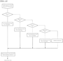
- FIG. 13 is a chart illustrating a laminating process condition according to types of films.
- a laminating apparatus 1 of the present invention has a structure as illustrated in FIGS. 1 to 4 .
- a sheet feed tray 3 is provided to a front side of an apparatus main body 2 , and an output tray 4 is provided to a rear side thereof.
- the sheet feed tray 3 is used for stacking sheets to be laminated.
- the apparatus main body 2 is configured such that an upper unit 5 is separable and openable, and the apparatus main body 2 and an internal mechanism provided below the upper unit 5 are reachable by hand so that operation such as film loading can be performed. Further, a film cassette 20 containing films for lamination, as illustrated in FIGS. 5 to 7 , is provided detachably so as to be removable upward from the apparatus main body 2 .
- a sheet is drawn into the main body using a draw-in roller 11 of a sheet feed mechanism unit 10 from sheets stacked on the sheet feed tray 3 .
- the draw-in roller 11 is lowered from above a sheet onto a surface of the sheet by an operation of a sheet feed solenoid. Note that the draw-in roller 11 is operated by receiving a drive force from a main motor via a sheet feed clutch.
- the draw-in roller 11 When a sheet feeding operation is performed, the draw-in roller 11 is brought into contact with the surface of the sheet by the operation of the sheet feed solenoid, and the main motor and the sheet feed clutch are operated to rotate the draw-in roller 11 , whereby the sheet is drawn into the sheet feed mechanism unit 10 in the apparatus main body 2 .
- the sheet drawn into the sheet feed mechanism unit 10 by the draw-in roller 11 is separated by a pair of rollers including an upper sheet feed roller 12 and a lower separation roller 13 (rotating in an opposite direction to the upper sheet feed roller 12 ). Even if a plurality of sheets are sent, only the top sheet is sent to a rear side of these rollers. In other words, the sheets other than the target one is drawn back to the sheet feed tray 3 side.
- the upper sheet feed roller 12 and the lower separation roller 13 are pressed against each other with a predetermined pressure by a spring mechanism. Further, the lower separation roller 13 has a torque limiter built therein. In a state where only one sheet is interposed, the lower separation roller 13 rotates in a forward direction while overcoming the torque limiter.
- the rotation of the upper sheet feed roller 12 starts rotation at the same timing as start of rotation of the draw-in roller 11 , and after a sheet reaches conveyance rollers 14 and 15 provided behind, the rotation is stopped.
- the lower separation roller 13 also operates at the same timing as the draw-in roller 11 . It should be noted that rotation of the upper sheet feed roller 12 and the draw-in roller 11 is driven by the main motor.
- the conveyance rollers 14 and 15 send a sheet sent from the upper sheet feed roller 12 to a press-bonding mechanism unit 30 provided behind, for press-bonding the sheet with a film fed from the film cassette 20 .
- the conveyance roller 14 on the upper side is driven by the main motor via the sheet feed clutch and rotates, and the lower conveyance roller 15 is in pressure contact with the conveyance roller 14 on the upper side by a spring mechanism to thereby rotate following the conveyance roller 14 on the upper side.
- the conveyance roller 14 on the upper side is driven by the main motor that drives the upper sheet feed roller 12 via a clutch, but is also driven via a conveyance clutch (electromagnetic clutch).
- the mechanism is configured such that when the conveyance clutch is connected, conveyance is performed at a high speed, while when the conveyance clutch is released, conveyance is performed at a low speed that is the same as a speed of the pressing rollers 31 and 32 of the press-bonding mechanism unit 30 described below.
- the conveyance clutch In the case of sending two or more sheets in succession for a laminating process, when the conveyance rollers 14 and 15 are started to feed the subsequent sheet, the conveyance clutch is connected to rotate the rollers at a high speed to thereby make an interval between the leading edge of the subsequent sheet and the trailing edge of the preceding sheet close to each other have a predetermined distance. After reaching the predetermined distance, the conveyance clutch is released and low-speed conveyance is performed at the same speed as that of the preceding sheet.
- the sheet feed mechanism unit 10 has a structure as described above, so that the interval between the preceding sheet and the subsequent sheet is shortened. When they have a constant interval, the sheet can be laminated after being conveyed at the same speed, and the interval between the sheets is kept at an appropriate constant interval. Accordingly, there is no waste of film after cutting.
- Each of the pressing rollers 31 and 32 has a quartz tube heater built therein, and temperature control is performed by detecting a temperature of the roller surface. Control is made such that when a temperature lower than a predetermined temperature is detected, the quartz tube heater is electrified, while when a temperature exceeding the predetermined temperature is detected, electrification of the quartz tube heater is stopped.
- the pressing rollers 31 and 32 and pull rollers 33 and 34 have a mechanism of applying pressure by upper and lower roller pairs, respectively.
- the pressure can be switched between pressurization and depressurization by closing the upper unit 5 and reciprocating left and right pressure levers 7 and 7 in a pair between predetermined positions.
- a sheet from the sheet feed mechanism unit 10 is sent between the films 21 a and 21 b sent from the film cassette 20 , and is press-bonded with the films 21 a and 21 b by the pair of pressing rollers 31 and 32 of the press-bonding mechanism unit 30 .
- cooling fans 35 and 35 are provided above and below the pull rollers 33 and 34 .
- the films 21 a and 21 b after being press-bonded by the pressing rollers 31 and 32 , are cooled to improve finishing quality of lamination.
- the press-bonded laminated object is sent between the pair of pull rollers 33 and 34 behind the pressing rollers 31 and 32 , and is further sent to a rotary cutter unit 40 behind them.
- a structure of the rotary cutter unit 40 is as illustrated in FIG. 11 .
- a rear end edge of the laminated object is allowed to pass through between upper and lower blades that are a rotary blade 42 and a fixed blade 41 in the rotary cutter unit 40 , and the fixed blade 41 is lowered so as to cut an intermediate portion between the trailing end of the previous sheet the leading end of the subsequent sheet and sandwich the cut portion with the rotary blade 42 , and then the rotary blade 42 is rotated to cut a laminated portion of the films 21 a and 21 b .
- Excessive laminated portions of the films 21 a and 21 b at a leading end portion of a first object and a trailing end portion of a last object are also cut in the same manner as the above method.
- the rotary blade 42 is driven by the main motor, and when the film reaches a predetermined portion to be cut via a stepping clutch therebetween, the stepping clutch is connected and driven for a predetermined time to perform control to rotate the rotary blade 42 by one turn.
- the fixed blade 41 and the rotary blade 42 sandwich the film only when the film is to be cut. At other times, a gap is left between the fixed blade 41 and the rotary blade 42 so as to allow the laminated object to pass thorough.
- the fixed blade 41 is energized in a direction of being brought into contact with the rotary blade 42 by a spring not illustrated. An end portion of the fixed blade 41 is brought into contact with a cam 43 provided at one end of the rotary blade 42 . A portion where the rotary blade 42 overlaps the fixed blade 41 is used as a cam recessed portion 43 a having a smaller diameter. Only when the fixed blade 41 is in contact with the cam recessed portion 43 a , the fixed blade 41 comes into contact with the rotary blade 42 to cut the film, and in other portions, the fixed blade 41 is separated from the rotary blade 42 against the force of the spring by the cam 43 . With this configuration, by only controlling the rotation of the rotary blade 42 at a predetermined position, a cutting operation and passage for conveyance of a laminated object are allowed.
- the cut laminated object is discharged to an outside of the apparatus main body 2 by discharge rollers 51 and 52 of a discharge unit 50 , and is stored on the output tray 4 .
- the film cassette 20 is configured such that cassette frames 27 and 28 on both sides are connected with use of a plurality of crossbars 29 so as to store the films 21 a and 21 b therein.
- the film cassette 20 has a mechanism that it is easily installable in and removable from the apparatus main body 2 by opening the upper unit 5 of the laminating apparatus 1 .
- the cassette 20 In the case of installing the cassette 20 , it is installed in the laminating apparatus 1 by holding upper portions of the left and right cassette frames 27 and 28 of the cassette 20 and inserting it from above the apparatus main body 2 into a below storage recess portion 6 .
- ends of the upper and lower films 21 a and 21 b are drawn to cause leading ends thereof to reach the outside of the laminating apparatus 1 from between the upper and lower discharge rollers 51 and 52 .
- the pair of pressing rollers 31 and 32 of the press-bonding mechanism unit 30 and the pair of pull rollers 33 and 34 are joined together, the discharge rollers 51 and 52 of the discharge unit 50 are also joined together, and further, the fixed blade 41 and the rotary blade 42 of the rotary cutter unit 40 are also joined together.
- the hard fixed blade 41 and the hard rotary blade 42 may be damaged if they collide with each other due to an operation of closing the upper unit 5 .
- FIG. 12(A) is a side view of the rotary cutter unit 40 illustrated in FIG. 11 .
- the rotary cutter unit 40 is configured of the fixed blade 41 and the rotary blade 42 , and rotates the rotary blade 42 in a clockwise direction while conveying the laminated object to thereby cut the laminated object in a width direction.
- the fixed blade 41 is pressed against the rotary blade 42 with a spring mechanism in the direction of an arrow “a” around the fulcrum 41 a .
- the fixed blade 41 When the cutting is completed, the fixed blade 41 is retracted from the passing position of the laminated object by the cam mechanism including the cam 43 fixed to the end of the rotary blade 42 illustrated in FIG. 11 .
- the fixed blade 41 has a mechanism that it returns to a laminated object passing position by the cam mechanism including the cam 43 immediately before cutting the laminated object and is in pressure contact with the rotary blade 42 .
- a protruding portion 44 b of a fixed blade control arm 44 fixed to the fixed blade 41 is energized in a direction of an arrow b, the fixed blade 41 can be separated from the rotary blade 42 against the spring mechanism.
- FIGS. 12(B) to 12(E) are side views of a mechanism in which when the fixed blade 41 and the rotary blade 42 illustrated in 12 (A) are in a positional relationship in which the rotary blade 42 collides with the fixed blade 41 at the rotation stop position when the upper unit 5 is closed, the fixed blade 41 is temporarily retracted from the rotary blade 42 and then returns it from a retracted state by a subsequent rotation of the rotary blade.
- the cam 45 is fixed to a shaft of the rotary blade 42 , and is coaxial with a rotary shaft of the rotary blade 42 .
- a portion (cam protruding portion 45 a ) where a distance from a center to a circumference is large is made to substantially coincide with an approximately 1 ⁇ 6 rotating portion where the blade exists on the circumference of the rotary blade 42 .
- An arm 46 that moves while abutting the cam 45 may or may not be in contact with the cam, depending on the position of the cam when the upper unit 5 is closed, to thereby act or not to act in a direction of energizing the protruding portion 44 b of the fixed blade control arm 44 .
- a rotary bearing 48 is added to assist smooth sliding movement with the cam 45 .
- the spring 47 acts on the arm 46 in a direction that allows a tip end portion (abutting portion 49 ), opposite to the tip end portion of the arm 46 , to which the rotary bearing 48 added, to abut against the protruding portion 44 b of the fixed blade control arm 44 fixed to the fixed blade 41 .
- an acting force is a force of a level that merely allows the tip abutting portion 49 of the arm 46 to abut the protruding portion 44 b when the arm 46 does not abut against the cam 45 , and is set to be very small compared with a force to allow the fixed blade 41 to be in pressure contact with the rotary blade 42 .
- the cam 45 does not press the arm 46 , and the arm 46 rotates in a clockwise direction by the spring 47 and the tip end portion opposite to the tip end portion to which the rotary bearing 48 of the arm 46 is added lightly abuts against the protruding portion 44 b of the fixed blade control arm 44 fixed to the fixed blade 41 .
- the rotary blade 42 starts rotation from a predetermined stop position at predetermined timing, and after the laminated object is cut, the rotary blade operates to make one turn from the start and stop at the original predetermined position.
- the stepped portion 45 b at the rotation leading end of the cam protruding portion 45 a of the cam 45 abuts against the rotary bearing 48 at the tip end portion of the arm 46 in an order of FIGS. 12(B), 12(C) , and 12 (D) in the clockwise direction to operate the arm 46 .
- the abutting portion 49 of the arm 46 does not strongly act on the protruding portion 44 b and does not affect the position of the fixed blade 41 . As a result, it does not affect the operation of cutting the laminated object.
- the cam 45 rotates in a clockwise direction in the drawing.
- it passes through the cam protruding portion 45 a of the cam 45 with respect to the movement of the rotary blade 42 thereafter, it moves in a direction opposite to the direction of separating the fixed blade 41 , as illustrated in FIGS. 12(B) to 12(D) . Accordingly, separating operation is not performed, and the laminated object can be cut.
- the idle rollers 25 a and 25 b provided to the film cassette 20 protrude rearward from the film cassette 20 in conjunction therewith.
- the films 21 a and 21 b passing through the idle rollers 25 a and 25 b are led by the pressing rollers 31 and 32 from the rear side of the pressing rollers 31 and 32 . Therefore, the films 21 a and 21 b are caught at a larger angle by the pressing rollers 31 and 32 , and a larger amount of heat is supplied, which contributes to an improvement in the press-bonding performance.
- the idle roller 25 a through which the upper film 21 a passes, is configured such that both ends thereof are pivotally supported by rear end portions of a pair of roller arms 26 a and 26 a that are provided inside the cassette frames 27 and 28 on both sides of the film cassette 20 and are movable in a predetermined range.
- a front end portion of the roller arm 26 a is pivotally supported by a shaft body 62 (although not illustrated in FIGS. 5 to 7 ) that is movable along a linear slits 61 provided in each of the both cassette frames 27 and 28 .
- the shaft body 62 that moves along the linear slits 61 of the respective two cassette frames 27 and 28 is provided to the respective two cassette frames 27 and 28 .
- T-shaped arms 63 are provided symmetrically to the two cassette frames 27 and 28 .
- the T-shaped arm 63 is pivotally supported by a shaft 64 of a portion where the two arms overlap, and is freely rotatable about the shaft 64 .
- a lower end of the T-shaped arm 63 engages with the shaft body 62 and moves in conjunction therewith.
- the shaft body 62 moves on a straight line along the straight slit 61
- the T-shaped arm 63 draws a circular arc around the shaft 64 . Therefore, an engaging portion of the T-shaped arm 63 with the shaft body 62 is formed as an elongated hole to which the shaft body 62 is inserted to engage with.
- An upper front end portion of the T-shaped arm 63 is an abutting portion 65 protruding in a left-right direction, and an upper rear end portion is engaged with a tension spring 66 provided between it and the cassette frame 27 or 28 .
- the T-shaped arm 63 is energized in a clockwise direction on the cassette frame 27 side, and in a counterclockwise direction on the cassette frame 28 side.
- An intermediate portion of the roller arm 26 a has a pin 67 a provided outward.
- the pin 67 a is movable along a curved slit 68 a formed in the cassette frames 27 and 28 .
- the lower idle roller 25 b is configured such that both ends thereof are pivotally supported by rear end portions of a pair of roller arms 26 b and 26 b which are provided inside the cassette frames 27 and 28 on both sides of the film cassette 20 and are movable within a predetermined range.
- a front end portion of the roller arm 26 b is pivotally supported by the shaft body 62 that moves along the linear slit 61 , similar to the upper roller arm 26 a described above.
- An intermediate portion of the roller arm 26 b has a pin 67 b provided outward.
- the pin 67 b is movable along a curved slit 68 b formed in the cassette frames 27 and 28 .
- the roller extrusion mechanism is configured as described above.
- the shaft body 62 is positioned at a front end of the linear slit 61 via the T-shaped arm 63 by an energizing force of a tension spring 66 . Therefore, the idle rollers 25 a and 25 b are accommodated inside the film cassette 20 as illustrated in FIGS. 5 to 7 .
- the films 21 a and 21 b are pulled out from the upper film holder 23 and the lower film holder 24 , respectively, and are set in the apparatus. Then, when the upper unit 5 covers it and closed, and the pressure levers 7 and 7 are moved to the predetermined positions, the abutting portion 65 of the T-shaped arm 63 is pushed downward in the film cassette 20 in a mechanically interlocked manner, although not illustrated.
- the shaft body 62 moves rearward along the linear slit 61 .
- the roller arms 26 a and 26 b are delivered backward while keeping the engagement of the pins 67 a and 67 b with the curved slits 68 a and 68 b , and the films 21 a and 21 b are wound around the pressing rollers 31 and 32 at a sufficient angle in the laminating apparatus 1 .
- Projection of the idle rollers 25 a and 25 b into the apparatus is performed by the movement of the pressure levers 7 and 7 as described above. However, it may be performed by means of another method. For example, a structure in which the abutting portion 65 of the T-shaped arm 63 is pushed down by an operation of closing the upper unit 5 is also acceptable.
- the idle rollers 25 a and 25 b into the apparatus main body 2 by utilizing a force when the film cassette 20 is pushed into the apparatus main body 2 and mounted, within a range where no mechanical interference occurs, and to accommodate the idle rollers 25 a and 25 b in the film cassette 20 according to an operation of taking out the film cassette 20 from the apparatus main body 2 .
- roller arms 26 a and 26 b are not limited to the structure illustrated and described.
- the mechanism can be changed as appropriate within a scope of the object of the present invention.
- the film cassette 20 has a structure in which two upper and lower films 21 a and 21 b can be loaded.
- the film 21 a or 21 b is wound around the film shaft 22 illustrated in FIG. 8(A) , to form a cylindrical shape, and the film shaft 22 with the film wound thereon is placed on an upper film holder 23 or a lower film holder 24 at a predetermined position of the film cassette 20 .
- recessed grooves 71 provided at two positions, that is, an inner upper portion of the cassette frame 27 and an inner lower portion of the cassette frame 28 of the film cassette 20
- recessed grooves 72 provided at two positions, that is, an inner lower portion of the cassette frame 27 and an inner upper portion of the cassette frame 28 of the film cassette 20 , and both end portions of the film shaft 22 are laid on and fixed to the recessed grooves 71 and the recessed grooves 72 , respectively.
- markings 22 a and 22 b are provided so that the film can be wound at a predetermined position on the film shaft 22 .
- dented marking 22 a having a film width of A4 and A3 and dented markings 22 b having a film width of B5 and B4 are provided on the film shaft 22 .
- the markings 22 a and 22 b are made into ring-shaped dents by cutting out the surface of the film shaft 22 . This is because in a case of protruding markings, when a film for A4 and A3 is wound, it is impossible to finely wind the film due to the protrusions of the markings for B5 and B4.
- the film may be delivered at a speed higher than a laminating process speed and the film may be sagged or wrinkled.
- end portions 22 c and 22 d of the film shaft 22 have a diameter larger than a diameter of a portion on which the film is wound so that the area of a flat portion of the end portion is enlarged. Thereby, a sliding area with the film cassette 20 side is increased and a sliding resistance value is increased to improve braking power of the film.
- a film has front and rear surfaces, that is, a surface to which heat-soluble glue is fixed and a surface without it.
- a surface sandwiching a medium for lamination must be a glue surface, it is necessary to load the film to the film cassette 20 in such a manner that the glue surface of the film is in a predetermined direction.
- the films 21 a and 21 b have directionality when they are loaded to the film cassette 20 .
- the left and right shapes differ from each other so as to prevent the film from being set in an opposite way between the film shaft 22 side and the film cassette 20 side.
- a vertical dimension of the recessed groove 71 is substantially the same as a diameter of the end portion 22 c of the film shaft 22 , and has a dimension that the end portion 22 c can pass through but the large diameter portion 22 e cannot pass through.
- a vertical dimension of the recessed groove 72 is substantially the same as the diameter of the large diameter portion 22 e in the vicinity of the end portion 22 d of the film shaft 22 , and has a dimension that allows passage of the large diameter portion 22 e .
- the recessed groove 71 and the recessed groove 72 are provided such that right and left are reversed.
- a recessed portion that fits the end portion 22 c of the film shaft 22 is provided, whereas on the other recessed groove 72 side, a recessed portion that fits 22 e in the vicinity of the end portion 22 d of the film shaft 22 is provided. Furthermore, on the side of the recessed groove 72 corresponding to the lower film holder 24 , a recessed portion that fits 22 e in the vicinity of the end portion 22 d of the film shaft 22 is provided, and on the other recessed groove 71 side, a recessed portion that fits the end portion 22 c of the film shaft 22 is provided. This realizes a structure in which one type of film wound around the film holder 22 in the same direction is used and a glue surface thereof faces a medium to be interposed.
- the film shaft 22 is pressed by the upper and lower compression springs 74 provided on the cassette frame 27 side, against the other end portion 22 d and the end portion 22 c .
- the end portion 22 c and the end portion 22 d having the large diameter portion 22 e adjacent thereto, of the film shaft 22 around which the film is wound are fitted in the recessed grooves 71 and 72 and held.
- the end portion 22 c and the end portion 22 d have a larger diameter than that of the shaft main body and have the same shape (end portions have the same area)
- a stable constant braking force is also applied from left and right. Accordingly, the film cam be loaded very easily, and there is no need to adjust the braking force thereafter.
- a mechanism for detecting a type of a film loaded to the film cassette 20 is provided on the film cassette 20 side and the apparatus main body 2 side.
- a lower portion of a cassette frame 28 in the film cassette 20 has a film identifying unit 80 consisting of four holes.
- Each of the four holes can be shut by a member, or opened and closed by means of a slide cover or the like.
- a position of each of the holes corresponds to a position of a switch provided to the apparatus main body 2 side, and it is configured that when the hole is shut, the switch is turned on, while when the hole is not shut, the switch is turned off (not turned on).
- the on/off operation is detected by a control unit on the apparatus main body 2 side, and in accordance with the detection, control of the main body side is switched by a routine as illustrated in FIG. 13 .
- Switches S 1 , S 2 , S 3 , and S 4 correspond to the respective films.
- the holes corresponding to the switches S 1 , S 2 , S 3 , and S 4 are shut or opened, respectively.
- control temperature of the laminating process is set to 90° C.
- switch S 2 when it is detected that the switch S 2 is turned on, it is determined that a film of 80 ⁇ is loaded, so that control for 95° C. is performed.
- switch S 3 is for 100 ⁇ film and control for 100° C. is performed, and that the switch S 4 is for 125 ⁇ and control for 105° C. is performed. In this way, control is performed to realize a better laminating process.
- the film detection sensor recognizes such a state, and displays that the film cassette is not installed and prohibits a laminating process to thereby prevent an erroneous operation of performing a laminating process without a film.
Landscapes
- Engineering & Computer Science (AREA)
- Mechanical Engineering (AREA)
- Manufacturing & Machinery (AREA)
- Physics & Mathematics (AREA)
- Fluid Mechanics (AREA)
- Lining Or Joining Of Plastics Or The Like (AREA)
- Folding Of Thin Sheet-Like Materials, Special Discharging Devices, And Others (AREA)
Abstract
Description
-
- 1 laminating apparatus
- 2 apparatus main body
- 3 sheet feed tray
- 4 output tray
- 5 upper unit
- 6 storage recess portion
- 7 pressure lever
- 10 sheet feed mechanism unit
- 11 draw-in roller
- 12 upper sheet feed roller
- 13 lower separation roller
- 14, 15 conveyance roller
- 20 cassette
- 21 a, 21 b film
- 22 film shaft
- 23 upper film holder
- 24 lower film holder
- 25 a, 25 b idle roller
- 26 a, 26 b roller arm
- 27, 28 cassette frame
- 29 crossbar
- 30 press-bonding mechanism unit
- 31, 32 pressing roller
- 33, 34 pull roller
- 35 fan
- 40 rotary cutter unit
- 41 fixed blade
- 41 a fulcrum
- 42 rotary blade
- 43 cam
- 43 a cam recess portion
- 44 fixed blade control arm
- 44 b protruding portion
- 45 cam
- 45 a cam projection
- 45 b cam step
- 46 arm
- 47 spring
- 48 rotary bearing
- 49 abutting portion
- 50 discharge unit
- 51, 52 discharge roller
- 60 roller extrusion mechanism
- 61 linear slit
- 62 shaft body
- 63 T-shape arm
- 64 axis
- 65 abutting portion
- 66 tension spring
- 67 a, 67 b pin
- 68 a, 68 b curved slit
- 71, 72 recessed groove
- 73 plate-shaped body
- 74 compression spring
- 80 film identifying unit
- 81 film detection lever
Claims (12)
Applications Claiming Priority (3)
| Application Number | Priority Date | Filing Date | Title |
|---|---|---|---|
| JP2016106345 | 2016-05-27 | ||
| JP2016-106345 | 2016-05-27 | ||
| PCT/JP2017/019775 WO2017204343A1 (en) | 2016-05-27 | 2017-05-26 | Laminating apparatus and film cassette and film shaft used for same |
Publications (2)
| Publication Number | Publication Date |
|---|---|
| US20190143663A1 US20190143663A1 (en) | 2019-05-16 |
| US11260643B2 true US11260643B2 (en) | 2022-03-01 |
Family
ID=60412375
Family Applications (1)
| Application Number | Title | Priority Date | Filing Date |
|---|---|---|---|
| US16/304,439 Active 2037-12-01 US11260643B2 (en) | 2016-05-27 | 2017-05-26 | Laminating apparatus, and film cassette and film shaft used therein |
Country Status (6)
| Country | Link |
|---|---|
| US (1) | US11260643B2 (en) |
| EP (1) | EP3466644B1 (en) |
| JP (1) | JP6938032B2 (en) |
| KR (1) | KR102414271B1 (en) |
| CN (1) | CN109195773B (en) |
| WO (1) | WO2017204343A1 (en) |
Families Citing this family (4)
| Publication number | Priority date | Publication date | Assignee | Title |
|---|---|---|---|---|
| CN110370613B (en) * | 2019-08-02 | 2023-09-22 | 江苏帝浦拓普智能装备有限公司 | Nut gasket film sticking machine |
| DE102022104955A1 (en) * | 2021-03-04 | 2022-09-08 | ACCO Brands Corporation | REFILLABLE LAMINATION CARTRIDGE SYSTEM AND ITS REFILL |
| CN114308546B (en) * | 2022-01-11 | 2022-10-11 | 海阳市凌晖包装有限公司 | Film rubber coating device convenient to adjust |
| CN119117754B (en) * | 2024-11-12 | 2025-05-30 | 江苏月之恒绒业有限公司 | Textile cloth winding device for spinning |
Citations (6)
| Publication number | Priority date | Publication date | Assignee | Title |
|---|---|---|---|---|
| JP2001079940A (en) | 1999-09-16 | 2001-03-27 | Brother Ind Ltd | Laminating equipment |
| JP2002166474A (en) * | 2000-11-30 | 2002-06-11 | Canon Inc | Laminating equipment |
| US6431243B1 (en) * | 1999-09-16 | 2002-08-13 | Brother Kogyo Kabushiki Kaisha | Laminating apparatus |
| JP2004243659A (en) | 2003-02-14 | 2004-09-02 | Pacral:Kk | Laminator |
| JP2006015516A (en) | 2004-06-30 | 2006-01-19 | Kyokuto Sanki Co Ltd | Hot laminator |
| US20070204961A1 (en) * | 2004-03-30 | 2007-09-06 | Yoshihiko Nakashima | Laminating Apparatus And Laminating Method |
Family Cites Families (16)
| Publication number | Priority date | Publication date | Assignee | Title |
|---|---|---|---|---|
| US4243464A (en) * | 1978-01-30 | 1981-01-06 | Potchen Thomas M | Laminating method |
| JPS58175907U (en) * | 1982-05-18 | 1983-11-25 | 松本 昭二 | Laminator with interlocking cutters |
| CA1294200C (en) * | 1988-04-04 | 1992-01-14 | Fumio Hamamura | Thin film laminating method and apparatus |
| JP2966058B2 (en) * | 1990-07-27 | 1999-10-25 | キヤノン株式会社 | Laminating equipment |
| JPH0611980A (en) * | 1992-06-26 | 1994-01-21 | Canon Aptecs Kk | Sheet material pressing device and laminating device |
| ITFI980031A1 (en) * | 1998-02-13 | 1999-08-13 | Perini Fabio Spa | EMBOSSING AND LAMINATING DEVICE FOR TAPE MATERIAL |
| JP4273279B2 (en) * | 1999-09-16 | 2009-06-03 | ブラザー工業株式会社 | Laminating apparatus and sheet cassette |
| JP4374710B2 (en) * | 2000-03-31 | 2009-12-02 | ブラザー工業株式会社 | Laminating apparatus and hot laminating unit |
| JP4465651B2 (en) * | 2004-03-30 | 2010-05-19 | ノーリツ鋼機株式会社 | Laminating apparatus and laminating method |
| JP4636322B2 (en) * | 2005-06-30 | 2011-02-23 | ノーリツ鋼機株式会社 | Laminating apparatus and magazine used therefor |
| DE112006002076B4 (en) * | 2005-08-05 | 2012-12-13 | General Binding Corp. | Film loading arrangement for laminator |
| US20070029437A1 (en) * | 2005-08-05 | 2007-02-08 | General Binding Corporation | Film loading arrangement for laminator |
| JP2008093863A (en) * | 2006-10-06 | 2008-04-24 | Fujipura Kk | Rolled film for laminator |
| US8960415B2 (en) * | 2010-06-15 | 2015-02-24 | Xyron, Inc. | Master processing apparatus with adjustably spaced pressure rollers |
| CN104340407B (en) * | 2013-08-06 | 2016-08-10 | 富鼎电子科技(嘉善)有限公司 | Automatic film sticking equipment |
| TWM512495U (en) * | 2014-12-08 | 2015-11-21 | Golden Arrow Printing Co Ltd | Paper and plastic products |
-
2017
- 2017-05-26 EP EP17802929.4A patent/EP3466644B1/en active Active
- 2017-05-26 WO PCT/JP2017/019775 patent/WO2017204343A1/en not_active Ceased
- 2017-05-26 US US16/304,439 patent/US11260643B2/en active Active
- 2017-05-26 CN CN201780032579.1A patent/CN109195773B/en active Active
- 2017-05-26 KR KR1020187033833A patent/KR102414271B1/en active Active
- 2017-05-26 JP JP2018519642A patent/JP6938032B2/en active Active
Patent Citations (6)
| Publication number | Priority date | Publication date | Assignee | Title |
|---|---|---|---|---|
| JP2001079940A (en) | 1999-09-16 | 2001-03-27 | Brother Ind Ltd | Laminating equipment |
| US6431243B1 (en) * | 1999-09-16 | 2002-08-13 | Brother Kogyo Kabushiki Kaisha | Laminating apparatus |
| JP2002166474A (en) * | 2000-11-30 | 2002-06-11 | Canon Inc | Laminating equipment |
| JP2004243659A (en) | 2003-02-14 | 2004-09-02 | Pacral:Kk | Laminator |
| US20070204961A1 (en) * | 2004-03-30 | 2007-09-06 | Yoshihiko Nakashima | Laminating Apparatus And Laminating Method |
| JP2006015516A (en) | 2004-06-30 | 2006-01-19 | Kyokuto Sanki Co Ltd | Hot laminator |
Also Published As
| Publication number | Publication date |
|---|---|
| WO2017204343A1 (en) | 2017-11-30 |
| KR20190011734A (en) | 2019-02-07 |
| JPWO2017204343A1 (en) | 2019-08-08 |
| CN109195773A (en) | 2019-01-11 |
| KR102414271B1 (en) | 2022-06-28 |
| EP3466644A4 (en) | 2020-05-13 |
| CN109195773B (en) | 2022-02-08 |
| EP3466644C0 (en) | 2023-07-05 |
| EP3466644A1 (en) | 2019-04-10 |
| JP6938032B2 (en) | 2021-09-22 |
| US20190143663A1 (en) | 2019-05-16 |
| EP3466644B1 (en) | 2023-07-05 |
Similar Documents
| Publication | Publication Date | Title |
|---|---|---|
| US11260643B2 (en) | Laminating apparatus, and film cassette and film shaft used therein | |
| US8585304B2 (en) | Label printer | |
| JP2011207074A5 (en) | ||
| EP2660017B1 (en) | Paper cutting device | |
| US9751338B2 (en) | Dual purpose printing apparatus | |
| US9399359B2 (en) | Image forming apparatus including switching member | |
| CN109195774B (en) | Laminating device | |
| US9205674B2 (en) | Simplex and duplex printer | |
| JP5785971B2 (en) | Printer device | |
| US9010224B2 (en) | Rotary cutter device | |
| JP6120070B2 (en) | Printing device | |
| US9061519B2 (en) | Printer apparatus and printing method | |
| US20120018484A1 (en) | Sheet feeding apparatus | |
| US20200316968A1 (en) | Thermal printer | |
| JP5390142B2 (en) | Thermal printer for single leaf tag and method for supplying the single leaf tag | |
| EP4737365A1 (en) | Printer | |
| JP2016088748A (en) | Image forming apparatus | |
| JP2004268295A (en) | Stencil process printing device | |
| US5667125A (en) | Device for transporting printing media in printers or copiers | |
| WO2022177015A1 (en) | Double-sided printer | |
| JP2015000479A (en) | Printer | |
| JP2014042994A (en) | Printer | |
| JP2005349832A (en) | Image formation device | |
| JPH0834408A (en) | Automatic sealing machine | |
| JP2010013108A (en) | Label pasting machine for envelope |
Legal Events
| Date | Code | Title | Description |
|---|---|---|---|
| AS | Assignment |
Owner name: LAMI CORPORATION INC., JAPAN Free format text: ASSIGNMENT OF ASSIGNORS INTEREST;ASSIGNORS:SUGATA, YOSHIHISA;MATSUSHITA, HIROMI;FUJIWARA, KATSUYOSHI;REEL/FRAME:047582/0181 Effective date: 20181116 |
|
| FEPP | Fee payment procedure |
Free format text: ENTITY STATUS SET TO UNDISCOUNTED (ORIGINAL EVENT CODE: BIG.); ENTITY STATUS OF PATENT OWNER: SMALL ENTITY |
|
| FEPP | Fee payment procedure |
Free format text: ENTITY STATUS SET TO SMALL (ORIGINAL EVENT CODE: SMAL); ENTITY STATUS OF PATENT OWNER: SMALL ENTITY |
|
| STPP | Information on status: patent application and granting procedure in general |
Free format text: DOCKETED NEW CASE - READY FOR EXAMINATION |
|
| STPP | Information on status: patent application and granting procedure in general |
Free format text: RESPONSE TO NON-FINAL OFFICE ACTION ENTERED AND FORWARDED TO EXAMINER |
|
| STPP | Information on status: patent application and granting procedure in general |
Free format text: FINAL REJECTION MAILED |
|
| STPP | Information on status: patent application and granting procedure in general |
Free format text: RESPONSE AFTER FINAL ACTION FORWARDED TO EXAMINER |
|
| STPP | Information on status: patent application and granting procedure in general |
Free format text: ADVISORY ACTION MAILED |
|
| STPP | Information on status: patent application and granting procedure in general |
Free format text: RESPONSE AFTER FINAL ACTION FORWARDED TO EXAMINER |
|
| STPP | Information on status: patent application and granting procedure in general |
Free format text: NOTICE OF ALLOWANCE MAILED -- APPLICATION RECEIVED IN OFFICE OF PUBLICATIONS |
|
| STCF | Information on status: patent grant |
Free format text: PATENTED CASE |
|
| MAFP | Maintenance fee payment |
Free format text: PAYMENT OF MAINTENANCE FEE, 4TH YR, SMALL ENTITY (ORIGINAL EVENT CODE: M2551); ENTITY STATUS OF PATENT OWNER: SMALL ENTITY Year of fee payment: 4 |