US11259754B2 - Wireless and noninvasive epidermal electronics - Google Patents
Wireless and noninvasive epidermal electronics Download PDFInfo
- Publication number
- US11259754B2 US11259754B2 US17/043,111 US201917043111A US11259754B2 US 11259754 B2 US11259754 B2 US 11259754B2 US 201917043111 A US201917043111 A US 201917043111A US 11259754 B2 US11259754 B2 US 11259754B2
- Authority
- US
- United States
- Prior art keywords
- flow
- actuator
- thermal
- skin
- conformable device
- Prior art date
- Legal status (The legal status is an assumption and is not a legal conclusion. Google has not performed a legal analysis and makes no representation as to the accuracy of the status listed.)
- Active
Links
- 238000011144 upstream manufacturing Methods 0.000 claims abstract description 66
- 239000000758 substrate Substances 0.000 claims abstract description 51
- 239000012530 fluid Substances 0.000 claims abstract description 45
- 210000001175 cerebrospinal fluid Anatomy 0.000 claims abstract description 28
- 208000003906 hydrocephalus Diseases 0.000 claims abstract description 22
- 230000002861 ventricular Effects 0.000 claims abstract description 20
- 238000004891 communication Methods 0.000 claims abstract description 13
- 239000010410 layer Substances 0.000 claims description 57
- 230000000694 effects Effects 0.000 claims description 29
- 239000000853 adhesive Substances 0.000 claims description 15
- 230000001070 adhesive effect Effects 0.000 claims description 15
- 238000005452 bending Methods 0.000 claims description 13
- 230000001052 transient effect Effects 0.000 claims description 13
- 238000005538 encapsulation Methods 0.000 claims description 10
- 230000004044 response Effects 0.000 claims description 8
- 238000012546 transfer Methods 0.000 claims description 7
- 230000001976 improved effect Effects 0.000 claims description 6
- 239000012790 adhesive layer Substances 0.000 claims description 5
- 239000010409 thin film Substances 0.000 claims description 5
- 238000000926 separation method Methods 0.000 claims description 4
- 238000007917 intracranial administration Methods 0.000 claims description 2
- 238000000034 method Methods 0.000 abstract description 40
- 230000001419 dependent effect Effects 0.000 abstract description 2
- 210000003491 skin Anatomy 0.000 description 99
- 238000005259 measurement Methods 0.000 description 80
- 239000000463 material Substances 0.000 description 33
- 238000005516 engineering process Methods 0.000 description 24
- 230000006870 function Effects 0.000 description 24
- -1 polydimethylsiloxane Polymers 0.000 description 23
- 206010062243 Shunt malfunction Diseases 0.000 description 19
- 229920001296 polysiloxane Polymers 0.000 description 19
- 230000003287 optical effect Effects 0.000 description 16
- 238000013459 approach Methods 0.000 description 15
- 239000006260 foam Substances 0.000 description 15
- 229920000642 polymer Polymers 0.000 description 15
- 239000004642 Polyimide Substances 0.000 description 13
- 238000001816 cooling Methods 0.000 description 13
- 238000001727 in vivo Methods 0.000 description 13
- 238000004519 manufacturing process Methods 0.000 description 13
- 229920001721 polyimide Polymers 0.000 description 13
- 238000001356 surgical procedure Methods 0.000 description 13
- 210000001519 tissue Anatomy 0.000 description 13
- 238000012544 monitoring process Methods 0.000 description 12
- 238000005070 sampling Methods 0.000 description 12
- 238000002474 experimental method Methods 0.000 description 11
- 229920000435 poly(dimethylsiloxane) Polymers 0.000 description 11
- 230000000875 corresponding effect Effects 0.000 description 10
- 239000004205 dimethyl polysiloxane Substances 0.000 description 10
- 229920001971 elastomer Polymers 0.000 description 10
- 238000003384 imaging method Methods 0.000 description 10
- 210000004204 blood vessel Anatomy 0.000 description 9
- 235000013870 dimethyl polysiloxane Nutrition 0.000 description 9
- 239000000806 elastomer Substances 0.000 description 9
- 238000004987 plasma desorption mass spectroscopy Methods 0.000 description 9
- 210000003462 vein Anatomy 0.000 description 9
- 238000004458 analytical method Methods 0.000 description 8
- 239000010949 copper Substances 0.000 description 8
- 238000013461 design Methods 0.000 description 8
- 238000010438 heat treatment Methods 0.000 description 8
- 238000000338 in vitro Methods 0.000 description 8
- 230000001965 increasing effect Effects 0.000 description 8
- 238000009413 insulation Methods 0.000 description 8
- 230000033001 locomotion Effects 0.000 description 8
- CXQXSVUQTKDNFP-UHFFFAOYSA-N octamethyltrisiloxane Chemical compound C[Si](C)(C)O[Si](C)(C)O[Si](C)(C)C CXQXSVUQTKDNFP-UHFFFAOYSA-N 0.000 description 8
- 238000012360 testing method Methods 0.000 description 8
- 239000010408 film Substances 0.000 description 7
- 230000007257 malfunction Effects 0.000 description 7
- 230000017531 blood circulation Effects 0.000 description 6
- 210000004556 brain Anatomy 0.000 description 6
- 230000007423 decrease Effects 0.000 description 6
- 208000005017 glioblastoma Diseases 0.000 description 6
- 239000002184 metal Substances 0.000 description 6
- 229910052751 metal Inorganic materials 0.000 description 6
- 239000000203 mixture Substances 0.000 description 6
- 238000012986 modification Methods 0.000 description 6
- 230000004048 modification Effects 0.000 description 6
- 230000008569 process Effects 0.000 description 6
- 238000012545 processing Methods 0.000 description 6
- 230000002035 prolonged effect Effects 0.000 description 6
- 238000001931 thermography Methods 0.000 description 6
- WYTGDNHDOZPMIW-RCBQFDQVSA-N alstonine Natural products C1=CC2=C3C=CC=CC3=NC2=C2N1C[C@H]1[C@H](C)OC=C(C(=O)OC)[C@H]1C2 WYTGDNHDOZPMIW-RCBQFDQVSA-N 0.000 description 5
- 238000003491 array Methods 0.000 description 5
- 230000005540 biological transmission Effects 0.000 description 5
- 238000006243 chemical reaction Methods 0.000 description 5
- 239000011651 chromium Substances 0.000 description 5
- 238000011161 development Methods 0.000 description 5
- 238000011156 evaluation Methods 0.000 description 5
- 230000014509 gene expression Effects 0.000 description 5
- 230000007774 longterm Effects 0.000 description 5
- 201000003077 normal pressure hydrocephalus Diseases 0.000 description 5
- 239000004814 polyurethane Substances 0.000 description 5
- 229920002635 polyurethane Polymers 0.000 description 5
- 230000001105 regulatory effect Effects 0.000 description 5
- 239000004065 semiconductor Substances 0.000 description 5
- 238000004088 simulation Methods 0.000 description 5
- 208000024891 symptom Diseases 0.000 description 5
- 229920002725 thermoplastic elastomer Polymers 0.000 description 5
- 238000012800 visualization Methods 0.000 description 5
- 239000004698 Polyethylene Substances 0.000 description 4
- 230000008901 benefit Effects 0.000 description 4
- 238000009529 body temperature measurement Methods 0.000 description 4
- 238000012512 characterization method Methods 0.000 description 4
- 229920001577 copolymer Polymers 0.000 description 4
- 230000008878 coupling Effects 0.000 description 4
- 238000010168 coupling process Methods 0.000 description 4
- 238000005859 coupling reaction Methods 0.000 description 4
- 230000032798 delamination Effects 0.000 description 4
- 238000009826 distribution Methods 0.000 description 4
- 229920005839 ecoflex® Polymers 0.000 description 4
- 239000011521 glass Substances 0.000 description 4
- 238000002595 magnetic resonance imaging Methods 0.000 description 4
- 230000036244 malformation Effects 0.000 description 4
- 239000011159 matrix material Substances 0.000 description 4
- 150000002739 metals Chemical class 0.000 description 4
- 239000000178 monomer Substances 0.000 description 4
- 230000035515 penetration Effects 0.000 description 4
- 210000004303 peritoneum Anatomy 0.000 description 4
- 229920000573 polyethylene Polymers 0.000 description 4
- 239000000700 radioactive tracer Substances 0.000 description 4
- 230000035945 sensitivity Effects 0.000 description 4
- 238000002604 ultrasonography Methods 0.000 description 4
- 206010010774 Constipation Diseases 0.000 description 3
- 206010019233 Headaches Diseases 0.000 description 3
- 230000006978 adaptation Effects 0.000 description 3
- 210000001367 artery Anatomy 0.000 description 3
- 239000008280 blood Substances 0.000 description 3
- 238000005266 casting Methods 0.000 description 3
- 239000002131 composite material Substances 0.000 description 3
- 150000001875 compounds Chemical class 0.000 description 3
- 238000002591 computed tomography Methods 0.000 description 3
- 238000010276 construction Methods 0.000 description 3
- 238000001514 detection method Methods 0.000 description 3
- 239000000975 dye Substances 0.000 description 3
- 231100000869 headache Toxicity 0.000 description 3
- 230000001939 inductive effect Effects 0.000 description 3
- 230000007794 irritation Effects 0.000 description 3
- 238000007726 management method Methods 0.000 description 3
- 238000013507 mapping Methods 0.000 description 3
- 229910044991 metal oxide Inorganic materials 0.000 description 3
- 230000000926 neurological effect Effects 0.000 description 3
- 230000003121 nonmonotonic effect Effects 0.000 description 3
- 238000000879 optical micrograph Methods 0.000 description 3
- 238000004806 packaging method and process Methods 0.000 description 3
- 238000001020 plasma etching Methods 0.000 description 3
- 229920001084 poly(chloroprene) Polymers 0.000 description 3
- 229920003229 poly(methyl methacrylate) Polymers 0.000 description 3
- 229920000728 polyester Polymers 0.000 description 3
- 239000004926 polymethyl methacrylate Substances 0.000 description 3
- 229920000098 polyolefin Polymers 0.000 description 3
- 230000009467 reduction Effects 0.000 description 3
- 230000002829 reductive effect Effects 0.000 description 3
- 238000011160 research Methods 0.000 description 3
- 210000004872 soft tissue Anatomy 0.000 description 3
- 238000005476 soldering Methods 0.000 description 3
- 239000000126 substance Substances 0.000 description 3
- XLYOFNOQVPJJNP-UHFFFAOYSA-N water Substances O XLYOFNOQVPJJNP-UHFFFAOYSA-N 0.000 description 3
- CSCPPACGZOOCGX-UHFFFAOYSA-N Acetone Chemical compound CC(C)=O CSCPPACGZOOCGX-UHFFFAOYSA-N 0.000 description 2
- NIXOWILDQLNWCW-UHFFFAOYSA-M Acrylate Chemical compound [O-]C(=O)C=C NIXOWILDQLNWCW-UHFFFAOYSA-M 0.000 description 2
- 206010073706 Cerebral ventricle collapse Diseases 0.000 description 2
- 206010010071 Coma Diseases 0.000 description 2
- 206010010904 Convulsion Diseases 0.000 description 2
- 208000018127 Idiopathic intracranial hypertension Diseases 0.000 description 2
- 206010022773 Intracranial pressure increased Diseases 0.000 description 2
- 206010025476 Malabsorption Diseases 0.000 description 2
- 208000004155 Malabsorption Syndromes Diseases 0.000 description 2
- 206010026865 Mass Diseases 0.000 description 2
- 206010028813 Nausea Diseases 0.000 description 2
- 206010028980 Neoplasm Diseases 0.000 description 2
- 208000012902 Nervous system disease Diseases 0.000 description 2
- PXHVJJICTQNCMI-UHFFFAOYSA-N Nickel Chemical compound [Ni] PXHVJJICTQNCMI-UHFFFAOYSA-N 0.000 description 2
- 239000004952 Polyamide Substances 0.000 description 2
- 239000005062 Polybutadiene Substances 0.000 description 2
- 229920002367 Polyisobutene Polymers 0.000 description 2
- 239000004743 Polypropylene Substances 0.000 description 2
- 208000001782 Slit Ventricle Syndrome Diseases 0.000 description 2
- 230000003187 abdominal effect Effects 0.000 description 2
- 230000001594 aberrant effect Effects 0.000 description 2
- 230000002159 abnormal effect Effects 0.000 description 2
- 230000001154 acute effect Effects 0.000 description 2
- 229910045601 alloy Inorganic materials 0.000 description 2
- 239000000956 alloy Substances 0.000 description 2
- 239000003990 capacitor Substances 0.000 description 2
- 210000004289 cerebral ventricle Anatomy 0.000 description 2
- 230000008859 change Effects 0.000 description 2
- 230000001684 chronic effect Effects 0.000 description 2
- 238000013170 computed tomography imaging Methods 0.000 description 2
- 230000003750 conditioning effect Effects 0.000 description 2
- 238000007405 data analysis Methods 0.000 description 2
- 230000034994 death Effects 0.000 description 2
- 230000003247 decreasing effect Effects 0.000 description 2
- 230000001627 detrimental effect Effects 0.000 description 2
- 238000012631 diagnostic technique Methods 0.000 description 2
- 230000003292 diminished effect Effects 0.000 description 2
- 239000003814 drug Substances 0.000 description 2
- 230000004064 dysfunction Effects 0.000 description 2
- 210000002615 epidermis Anatomy 0.000 description 2
- 230000001747 exhibiting effect Effects 0.000 description 2
- 238000009472 formulation Methods 0.000 description 2
- 230000036541 health Effects 0.000 description 2
- 230000002008 hemorrhagic effect Effects 0.000 description 2
- 238000007654 immersion Methods 0.000 description 2
- 230000003116 impacting effect Effects 0.000 description 2
- 230000006872 improvement Effects 0.000 description 2
- 208000015181 infectious disease Diseases 0.000 description 2
- 238000003331 infrared imaging Methods 0.000 description 2
- 208000014674 injury Diseases 0.000 description 2
- 201000009941 intracranial hypertension Diseases 0.000 description 2
- 230000001404 mediated effect Effects 0.000 description 2
- 150000004706 metal oxides Chemical class 0.000 description 2
- 230000000116 mitigating effect Effects 0.000 description 2
- 238000000465 moulding Methods 0.000 description 2
- 230000008693 nausea Effects 0.000 description 2
- 229920001778 nylon Polymers 0.000 description 2
- 238000012856 packing Methods 0.000 description 2
- 230000036961 partial effect Effects 0.000 description 2
- 230000037361 pathway Effects 0.000 description 2
- 210000003200 peritoneal cavity Anatomy 0.000 description 2
- 238000000206 photolithography Methods 0.000 description 2
- 230000000704 physical effect Effects 0.000 description 2
- 229920002647 polyamide Polymers 0.000 description 2
- 229920002857 polybutadiene Polymers 0.000 description 2
- 239000004417 polycarbonate Substances 0.000 description 2
- 229920000515 polycarbonate Polymers 0.000 description 2
- 229920001843 polymethylhydrosiloxane Polymers 0.000 description 2
- 229920001155 polypropylene Polymers 0.000 description 2
- 230000002980 postoperative effect Effects 0.000 description 2
- 208000001381 pseudotumor cerebri Diseases 0.000 description 2
- 230000005855 radiation Effects 0.000 description 2
- 230000009103 reabsorption Effects 0.000 description 2
- 229920005989 resin Polymers 0.000 description 2
- 239000011347 resin Substances 0.000 description 2
- 210000005245 right atrium Anatomy 0.000 description 2
- 238000004528 spin coating Methods 0.000 description 2
- 238000011477 surgical intervention Methods 0.000 description 2
- 229920003051 synthetic elastomer Polymers 0.000 description 2
- 239000005061 synthetic rubber Substances 0.000 description 2
- 230000000930 thermomechanical effect Effects 0.000 description 2
- 238000003325 tomography Methods 0.000 description 2
- 230000008733 trauma Effects 0.000 description 2
- 239000013598 vector Substances 0.000 description 2
- 210000000707 wrist Anatomy 0.000 description 2
- FPIPGXGPPPQFEQ-UHFFFAOYSA-N 13-cis retinol Natural products OCC=C(C)C=CC=C(C)C=CC1=C(C)CCCC1(C)C FPIPGXGPPPQFEQ-UHFFFAOYSA-N 0.000 description 1
- 241001247482 Amsonia Species 0.000 description 1
- 208000019901 Anxiety disease Diseases 0.000 description 1
- 229930091051 Arenine Natural products 0.000 description 1
- 238000012935 Averaging Methods 0.000 description 1
- 208000034577 Benign intracranial hypertension Diseases 0.000 description 1
- 208000014882 Carotid artery disease Diseases 0.000 description 1
- VYZAMTAEIAYCRO-UHFFFAOYSA-N Chromium Chemical compound [Cr] VYZAMTAEIAYCRO-UHFFFAOYSA-N 0.000 description 1
- 206010010356 Congenital anomaly Diseases 0.000 description 1
- 206010012289 Dementia Diseases 0.000 description 1
- 241001379910 Ephemera danica Species 0.000 description 1
- 208000036993 Frustration Diseases 0.000 description 1
- 201000010915 Glioblastoma multiforme Diseases 0.000 description 1
- 208000002250 Hematologic Neoplasms Diseases 0.000 description 1
- 208000032843 Hemorrhage Diseases 0.000 description 1
- 244000043261 Hevea brasiliensis Species 0.000 description 1
- 208000032984 Intraoperative Complications Diseases 0.000 description 1
- 206010024264 Lethargy Diseases 0.000 description 1
- 208000035752 Live birth Diseases 0.000 description 1
- 229920001890 Novodur Polymers 0.000 description 1
- 239000004677 Nylon Substances 0.000 description 1
- 235000014676 Phragmites communis Nutrition 0.000 description 1
- 239000004696 Poly ether ether ketone Substances 0.000 description 1
- 239000004693 Polybenzimidazole Substances 0.000 description 1
- 239000004697 Polyetherimide Substances 0.000 description 1
- 239000004721 Polyphenylene oxide Substances 0.000 description 1
- 239000004734 Polyphenylene sulfide Substances 0.000 description 1
- 239000004954 Polyphthalamide Substances 0.000 description 1
- 239000004793 Polystyrene Substances 0.000 description 1
- 239000004820 Pressure-sensitive adhesive Substances 0.000 description 1
- 206010057765 Procedural complication Diseases 0.000 description 1
- XUIMIQQOPSSXEZ-UHFFFAOYSA-N Silicon Chemical compound [Si] XUIMIQQOPSSXEZ-UHFFFAOYSA-N 0.000 description 1
- 208000032140 Sleepiness Diseases 0.000 description 1
- 206010041349 Somnolence Diseases 0.000 description 1
- 239000002174 Styrene-butadiene Substances 0.000 description 1
- 208000002667 Subdural Hematoma Diseases 0.000 description 1
- 206010046543 Urinary incontinence Diseases 0.000 description 1
- 206010048671 Venous stenosis Diseases 0.000 description 1
- FPIPGXGPPPQFEQ-BOOMUCAASA-N Vitamin A Natural products OC/C=C(/C)\C=C\C=C(\C)/C=C/C1=C(C)CCCC1(C)C FPIPGXGPPPQFEQ-BOOMUCAASA-N 0.000 description 1
- 230000004308 accommodation Effects 0.000 description 1
- 238000009825 accumulation Methods 0.000 description 1
- 150000001252 acrylic acid derivatives Chemical class 0.000 description 1
- NIXOWILDQLNWCW-UHFFFAOYSA-N acrylic acid group Chemical group C(C=C)(=O)O NIXOWILDQLNWCW-UHFFFAOYSA-N 0.000 description 1
- 230000002411 adverse Effects 0.000 description 1
- FPIPGXGPPPQFEQ-OVSJKPMPSA-N all-trans-retinol Chemical compound OC\C=C(/C)\C=C\C=C(/C)\C=C\C1=C(C)CCCC1(C)C FPIPGXGPPPQFEQ-OVSJKPMPSA-N 0.000 description 1
- 230000004075 alteration Effects 0.000 description 1
- 229910052782 aluminium Inorganic materials 0.000 description 1
- XAGFODPZIPBFFR-UHFFFAOYSA-N aluminium Chemical compound [Al] XAGFODPZIPBFFR-UHFFFAOYSA-N 0.000 description 1
- 230000003444 anaesthetic effect Effects 0.000 description 1
- 238000002583 angiography Methods 0.000 description 1
- 230000036506 anxiety Effects 0.000 description 1
- 230000004872 arterial blood pressure Effects 0.000 description 1
- 238000003556 assay Methods 0.000 description 1
- 230000000712 assembly Effects 0.000 description 1
- 238000000429 assembly Methods 0.000 description 1
- 229920002988 biodegradable polymer Polymers 0.000 description 1
- 239000004621 biodegradable polymer Substances 0.000 description 1
- 239000012620 biological material Substances 0.000 description 1
- 238000010170 biological method Methods 0.000 description 1
- 210000004369 blood Anatomy 0.000 description 1
- 238000009530 blood pressure measurement Methods 0.000 description 1
- 210000000988 bone and bone Anatomy 0.000 description 1
- MTAZNLWOLGHBHU-UHFFFAOYSA-N butadiene-styrene rubber Chemical compound C=CC=C.C=CC1=CC=CC=C1 MTAZNLWOLGHBHU-UHFFFAOYSA-N 0.000 description 1
- 238000011088 calibration curve Methods 0.000 description 1
- 201000011510 cancer Diseases 0.000 description 1
- 230000000747 cardiac effect Effects 0.000 description 1
- 239000003153 chemical reaction reagent Substances 0.000 description 1
- 210000003161 choroid Anatomy 0.000 description 1
- 229910052804 chromium Inorganic materials 0.000 description 1
- 210000003109 clavicle Anatomy 0.000 description 1
- 230000003749 cleanliness Effects 0.000 description 1
- 238000003759 clinical diagnosis Methods 0.000 description 1
- 239000003086 colorant Substances 0.000 description 1
- 238000011109 contamination Methods 0.000 description 1
- 230000001276 controlling effect Effects 0.000 description 1
- 229910052802 copper Inorganic materials 0.000 description 1
- 230000002596 correlated effect Effects 0.000 description 1
- 229920006037 cross link polymer Polymers 0.000 description 1
- 230000006378 damage Effects 0.000 description 1
- 238000003745 diagnosis Methods 0.000 description 1
- 238000002405 diagnostic procedure Methods 0.000 description 1
- 238000010586 diagram Methods 0.000 description 1
- 201000010099 disease Diseases 0.000 description 1
- 208000037265 diseases, disorders, signs and symptoms Diseases 0.000 description 1
- 239000002019 doping agent Substances 0.000 description 1
- 229940079593 drug Drugs 0.000 description 1
- 230000005489 elastic deformation Effects 0.000 description 1
- 238000005566 electron beam evaporation Methods 0.000 description 1
- 230000008030 elimination Effects 0.000 description 1
- 238000003379 elimination reaction Methods 0.000 description 1
- 238000011067 equilibration Methods 0.000 description 1
- 238000005530 etching Methods 0.000 description 1
- 238000000605 extraction Methods 0.000 description 1
- 230000005669 field effect Effects 0.000 description 1
- 238000013100 final test Methods 0.000 description 1
- 229920002313 fluoropolymer Polymers 0.000 description 1
- 239000004811 fluoropolymer Substances 0.000 description 1
- ZZUFCTLCJUWOSV-UHFFFAOYSA-N furosemide Chemical compound C1=C(Cl)C(S(=O)(=O)N)=CC(C(O)=O)=C1NCC1=CC=CO1 ZZUFCTLCJUWOSV-UHFFFAOYSA-N 0.000 description 1
- 230000005021 gait Effects 0.000 description 1
- 230000017525 heat dissipation Effects 0.000 description 1
- 229920001519 homopolymer Polymers 0.000 description 1
- 230000002209 hydrophobic effect Effects 0.000 description 1
- 230000001771 impaired effect Effects 0.000 description 1
- 238000002513 implantation Methods 0.000 description 1
- 238000011065 in-situ storage Methods 0.000 description 1
- 238000010348 incorporation Methods 0.000 description 1
- 239000004615 ingredient Substances 0.000 description 1
- 229920000592 inorganic polymer Polymers 0.000 description 1
- 230000010354 integration Effects 0.000 description 1
- 230000003993 interaction Effects 0.000 description 1
- 239000011229 interlayer Substances 0.000 description 1
- 230000001788 irregular Effects 0.000 description 1
- 239000002648 laminated material Substances 0.000 description 1
- 238000010030 laminating Methods 0.000 description 1
- 238000003475 lamination Methods 0.000 description 1
- 238000003698 laser cutting Methods 0.000 description 1
- 239000012705 liquid precursor Substances 0.000 description 1
- 238000013332 literature search Methods 0.000 description 1
- 210000004185 liver Anatomy 0.000 description 1
- 229920002521 macromolecule Polymers 0.000 description 1
- 230000007246 mechanism Effects 0.000 description 1
- 229920002529 medical grade silicone Polymers 0.000 description 1
- 210000004379 membrane Anatomy 0.000 description 1
- 239000012528 membrane Substances 0.000 description 1
- 230000003340 mental effect Effects 0.000 description 1
- 230000004060 metabolic process Effects 0.000 description 1
- 238000003801 milling Methods 0.000 description 1
- 229920003052 natural elastomer Polymers 0.000 description 1
- 229920001194 natural rubber Polymers 0.000 description 1
- 231100000878 neurological injury Toxicity 0.000 description 1
- 229910052759 nickel Inorganic materials 0.000 description 1
- 150000002825 nitriles Chemical class 0.000 description 1
- 231100000344 non-irritating Toxicity 0.000 description 1
- 229920000620 organic polymer Polymers 0.000 description 1
- 238000012261 overproduction Methods 0.000 description 1
- 238000012858 packaging process Methods 0.000 description 1
- 238000007427 paired t-test Methods 0.000 description 1
- 206010033675 panniculitis Diseases 0.000 description 1
- 230000003071 parasitic effect Effects 0.000 description 1
- 230000007170 pathology Effects 0.000 description 1
- 230000007310 pathophysiology Effects 0.000 description 1
- 230000000737 periodic effect Effects 0.000 description 1
- 230000035479 physiological effects, processes and functions Effects 0.000 description 1
- 229920003023 plastic Polymers 0.000 description 1
- 239000004033 plastic Substances 0.000 description 1
- 210000004224 pleura Anatomy 0.000 description 1
- 210000003281 pleural cavity Anatomy 0.000 description 1
- 229920002239 polyacrylonitrile Polymers 0.000 description 1
- 229920001230 polyarylate Polymers 0.000 description 1
- 229920002480 polybenzimidazole Polymers 0.000 description 1
- 229920001748 polybutylene Polymers 0.000 description 1
- 229920002530 polyetherether ketone Polymers 0.000 description 1
- 229920001601 polyetherimide Polymers 0.000 description 1
- 229920000139 polyethylene terephthalate Polymers 0.000 description 1
- 239000005020 polyethylene terephthalate Substances 0.000 description 1
- 229920001470 polyketone Polymers 0.000 description 1
- 238000006116 polymerization reaction Methods 0.000 description 1
- 239000011116 polymethylpentene Substances 0.000 description 1
- 229920000306 polymethylpentene Polymers 0.000 description 1
- 229920006324 polyoxymethylene Polymers 0.000 description 1
- 229920006380 polyphenylene oxide Polymers 0.000 description 1
- 229920000069 polyphenylene sulfide Polymers 0.000 description 1
- 229920006375 polyphtalamide Polymers 0.000 description 1
- 229920002223 polystyrene Polymers 0.000 description 1
- 239000011496 polyurethane foam Substances 0.000 description 1
- 239000004800 polyvinyl chloride Substances 0.000 description 1
- 229920000915 polyvinyl chloride Polymers 0.000 description 1
- 238000003825 pressing Methods 0.000 description 1
- 230000002265 prevention Effects 0.000 description 1
- 238000000746 purification Methods 0.000 description 1
- 238000004445 quantitative analysis Methods 0.000 description 1
- 238000009877 rendering Methods 0.000 description 1
- 230000002441 reversible effect Effects 0.000 description 1
- 239000005060 rubber Substances 0.000 description 1
- 238000007665 sagging Methods 0.000 description 1
- 238000004335 scaling law Methods 0.000 description 1
- 230000035807 sensation Effects 0.000 description 1
- 229920000260 silastic Polymers 0.000 description 1
- 229910052710 silicon Inorganic materials 0.000 description 1
- 239000010703 silicon Substances 0.000 description 1
- 229920005573 silicon-containing polymer Polymers 0.000 description 1
- 239000013464 silicone adhesive Substances 0.000 description 1
- 229920002379 silicone rubber Polymers 0.000 description 1
- 239000004945 silicone rubber Substances 0.000 description 1
- 238000004513 sizing Methods 0.000 description 1
- 239000007779 soft material Substances 0.000 description 1
- 229910000679 solder Inorganic materials 0.000 description 1
- 239000007787 solid Substances 0.000 description 1
- 230000003595 spectral effect Effects 0.000 description 1
- 239000007858 starting material Substances 0.000 description 1
- 238000007619 statistical method Methods 0.000 description 1
- 230000004936 stimulating effect Effects 0.000 description 1
- 239000004575 stone Substances 0.000 description 1
- 239000011115 styrene butadiene Substances 0.000 description 1
- 229920003048 styrene butadiene rubber Polymers 0.000 description 1
- 238000007920 subcutaneous administration Methods 0.000 description 1
- 210000004304 subcutaneous tissue Anatomy 0.000 description 1
- 125000001424 substituent group Chemical group 0.000 description 1
- 150000003457 sulfones Chemical class 0.000 description 1
- 210000004243 sweat Anatomy 0.000 description 1
- 238000010189 synthetic method Methods 0.000 description 1
- 230000009897 systematic effect Effects 0.000 description 1
- 230000009885 systemic effect Effects 0.000 description 1
- 230000002123 temporal effect Effects 0.000 description 1
- 229920001169 thermoplastic Polymers 0.000 description 1
- 239000004416 thermosoftening plastic Substances 0.000 description 1
- 231100000331 toxic Toxicity 0.000 description 1
- 230000002588 toxic effect Effects 0.000 description 1
- 230000009466 transformation Effects 0.000 description 1
- 230000001131 transforming effect Effects 0.000 description 1
- 238000010200 validation analysis Methods 0.000 description 1
- 230000002792 vascular Effects 0.000 description 1
- 210000005166 vasculature Anatomy 0.000 description 1
- 230000008320 venous blood flow Effects 0.000 description 1
- 125000000391 vinyl group Chemical group [H]C([*])=C([H])[H] 0.000 description 1
- 229920002554 vinyl polymer Polymers 0.000 description 1
- 230000000007 visual effect Effects 0.000 description 1
- 235000019155 vitamin A Nutrition 0.000 description 1
- 239000011719 vitamin A Substances 0.000 description 1
- 229940045997 vitamin a Drugs 0.000 description 1
- 230000002618 waking effect Effects 0.000 description 1
Images


Classifications
-
- A—HUMAN NECESSITIES
- A61—MEDICAL OR VETERINARY SCIENCE; HYGIENE
- A61B—DIAGNOSIS; SURGERY; IDENTIFICATION
- A61B5/00—Measuring for diagnostic purposes; Identification of persons
- A61B5/01—Measuring temperature of body parts ; Diagnostic temperature sensing, e.g. for malignant or inflamed tissue
-
- A—HUMAN NECESSITIES
- A61—MEDICAL OR VETERINARY SCIENCE; HYGIENE
- A61B—DIAGNOSIS; SURGERY; IDENTIFICATION
- A61B5/00—Measuring for diagnostic purposes; Identification of persons
- A61B5/72—Signal processing specially adapted for physiological signals or for diagnostic purposes
- A61B5/7271—Specific aspects of physiological measurement analysis
- A61B5/7278—Artificial waveform generation or derivation, e.g. synthesizing signals from measured signals
-
- A—HUMAN NECESSITIES
- A61—MEDICAL OR VETERINARY SCIENCE; HYGIENE
- A61B—DIAGNOSIS; SURGERY; IDENTIFICATION
- A61B5/00—Measuring for diagnostic purposes; Identification of persons
-
- A—HUMAN NECESSITIES
- A61—MEDICAL OR VETERINARY SCIENCE; HYGIENE
- A61B—DIAGNOSIS; SURGERY; IDENTIFICATION
- A61B5/00—Measuring for diagnostic purposes; Identification of persons
- A61B5/02—Detecting, measuring or recording for evaluating the cardiovascular system, e.g. pulse, heart rate, blood pressure or blood flow
- A61B5/026—Measuring blood flow
-
- A—HUMAN NECESSITIES
- A61—MEDICAL OR VETERINARY SCIENCE; HYGIENE
- A61B—DIAGNOSIS; SURGERY; IDENTIFICATION
- A61B5/00—Measuring for diagnostic purposes; Identification of persons
- A61B5/03—Measuring fluid pressure within the body other than blood pressure, e.g. cerebral pressure ; Measuring pressure in body tissues or organs
- A61B5/031—Intracranial pressure
-
- A—HUMAN NECESSITIES
- A61—MEDICAL OR VETERINARY SCIENCE; HYGIENE
- A61B—DIAGNOSIS; SURGERY; IDENTIFICATION
- A61B5/00—Measuring for diagnostic purposes; Identification of persons
- A61B5/145—Measuring characteristics of blood in vivo, e.g. gas concentration or pH-value ; Measuring characteristics of body fluids or tissues, e.g. interstitial fluid or cerebral tissue
- A61B5/14507—Measuring characteristics of blood in vivo, e.g. gas concentration or pH-value ; Measuring characteristics of body fluids or tissues, e.g. interstitial fluid or cerebral tissue specially adapted for measuring characteristics of body fluids other than blood
-
- A—HUMAN NECESSITIES
- A61—MEDICAL OR VETERINARY SCIENCE; HYGIENE
- A61B—DIAGNOSIS; SURGERY; IDENTIFICATION
- A61B2562/00—Details of sensors; Constructional details of sensor housings or probes; Accessories for sensors
- A61B2562/02—Details of sensors specially adapted for in-vivo measurements
- A61B2562/0271—Thermal or temperature sensors
-
- A—HUMAN NECESSITIES
- A61—MEDICAL OR VETERINARY SCIENCE; HYGIENE
- A61B—DIAGNOSIS; SURGERY; IDENTIFICATION
- A61B2562/00—Details of sensors; Constructional details of sensor housings or probes; Accessories for sensors
- A61B2562/02—Details of sensors specially adapted for in-vivo measurements
- A61B2562/028—Microscale sensors, e.g. electromechanical sensors [MEMS]
-
- A—HUMAN NECESSITIES
- A61—MEDICAL OR VETERINARY SCIENCE; HYGIENE
- A61B—DIAGNOSIS; SURGERY; IDENTIFICATION
- A61B2562/00—Details of sensors; Constructional details of sensor housings or probes; Accessories for sensors
- A61B2562/04—Arrangements of multiple sensors of the same type
- A61B2562/046—Arrangements of multiple sensors of the same type in a matrix array
-
- A—HUMAN NECESSITIES
- A61—MEDICAL OR VETERINARY SCIENCE; HYGIENE
- A61B—DIAGNOSIS; SURGERY; IDENTIFICATION
- A61B2562/00—Details of sensors; Constructional details of sensor housings or probes; Accessories for sensors
- A61B2562/16—Details of sensor housings or probes; Details of structural supports for sensors
- A61B2562/164—Details of sensor housings or probes; Details of structural supports for sensors the sensor is mounted in or on a conformable substrate or carrier
-
- A—HUMAN NECESSITIES
- A61—MEDICAL OR VETERINARY SCIENCE; HYGIENE
- A61B—DIAGNOSIS; SURGERY; IDENTIFICATION
- A61B2562/00—Details of sensors; Constructional details of sensor housings or probes; Accessories for sensors
- A61B2562/18—Shielding or protection of sensors from environmental influences, e.g. protection from mechanical damage
-
- A—HUMAN NECESSITIES
- A61—MEDICAL OR VETERINARY SCIENCE; HYGIENE
- A61B—DIAGNOSIS; SURGERY; IDENTIFICATION
- A61B5/00—Measuring for diagnostic purposes; Identification of persons
- A61B5/48—Other medical applications
- A61B5/4851—Prosthesis assessment or monitoring
Definitions
- Hydrocephalus and shunt-related expenditures cost the US system over $2 billion dollars in annual expenses, with 125,000 shunt surgeries per year and an untreated mortality rate estimated at 50-60%.
- Existing diagnostics are expensive, inaccurate, and often harmful or invasive, and can lead to unnecessary admissions, further testing, or needless surgery.
- a noninvasive, thermal biosensor capable of diagnosing ventricular shunt malfunction.
- Hydrocephalus is a common and costly condition caused by the accumulation of cerebrospinal fluid in the brain. It occurs in 1-5 of every 1000 live births, and over 70,000 patients are admitted and diagnosed yearly in the United States. Cerebrospinal fluid (CSF) is produced within the ventricles of the brain and is responsible for its nourishment and protection, but dysfunction in its drainage or reabsorption can lead to devastating neurological complications. Symptoms may include headache, lethargy, seizures, coma, or death, and untreated hydrocephalus has a mortality rate estimated at 50-60%. Pediatric hydrocephalus accounts for 38% of patients, and related surgeries are the most common neurosurgical procedures performed in children.
- CSF Cerebrospinal fluid
- ShuntCheck® utilizes an ice-pack based thermal cooling system connected to a Windows PC DAQ to address a need for shunt monitoring. That technology, however, is cumbersome and time-consuming. The device's cumbersome, multi-step protocol; equivocal or negative past clinical studies; and need for ice-pack cooling have limited its acceptance. Additionally, patient discomfort due to prolonged skin cooling (detrimental for pediatric diagnostics) and absence of chronic monitoring further limits its diagnostic relevance. Accordingly, there is a need for a wireless noninvasive shunt diagnostic, that is conformable to skin and has epidermal-like mechanical properties.
- the devices presented herein provide a platform for measuring flow in subdermal conduits and are advantageously non-invasive and rapid, while preserving a high level of accuracy.
- the devices may be conformal to skin and wireless without a need for hard-wire connection to bulky external components, such as controllers, digital monitors and power supplies. In this manner, the device is painless and non-obtrusive to a patient, akin to wearing an adhesive bandage.
- shunt malfunction specifically ventricular shunts.
- Extended use can capture occult malfunction, akin to a holter monitor for cerebrospinal fluid.
- a soft, wireless, noninvasive, non-surgical, skin-mounted device for the continuous measurement of fluid flow in a subdermal conduit, such as shunt-based CSF flow.
- the epidermal device exploits the precise measurement of thermal transport to characterize CSF flow in underlaid shunts.
- the device platform is ultrathin ( ⁇ 100 ⁇ m), soft (70 kPa), flexible resulting in a continuously wearable device mechanically invisible to the wearer. Similar in size to a Band-Aid® adhesive bandage, the device is composed primarily of soft, silicone rubber (no hard edges) and transmits recorded data wirelessly via Bluetooth to a companion mobile app. Patient data and in vitro tests confirm device efficacy in producing clinical-quality data suitable for shunt malfunction diagnostics.
- a carrier substrate having an open passage through a central portion of the carrier substrate may be provided around the active sensors region, where intimate conformal contact is desired.
- the carrier substrate may have a relatively larger mechanical parameter compared to the substrate that supports the sensors, such as being less flexible, elastic and/or soft, so that the device can be handled in a manner similar to an adhesive bandage (e.g., does not tear during application and use) but without sacrificing conformability and patient comfort.
- the devices and methods described herein provide a fundamental platform for measuring flow in a wide range of artificial and natural flow conduits. Examples include, but are not limited to, catheters, stents and blood vessels.
- various conformable devices capable of reliably, accurately, and continuously measuring subdermal fluid flow, including in a conduit.
- Various active components are supported by a substrate, such as a substrate that is characterized as soft, stretchable and flexible.
- a thermal actuator, an upstream temperature sensor and a downstream temperature sensor is supported by the substrate.
- a microprocessor is in electronic communication with the temperature sensors and other relevant components, such as the actuator, to calculate subdermal fluid flow from the measured upstream and downstream temperatures.
- Any of the devices may be wireless, further facilitating low patient impact monitoring, including without a need for hard-wire connections. In this manner, the patient may even return to home, without adversely impacting monitoring.
- any of the devices described herein may have additional temperature sensors.
- the position of those sensors may be described relative to a notional line (e.g., imaginary) line that is formed by drawing a line over spatially aligned upstream sensor, actuator, and downstream sensor.
- the additional sensors function as reference sensors and assist with determining various skin properties and related convection-type properties, for example, useful in determining fluid flow rate and the effect of the actuator independent of flow.
- at least one sensor is positioned so that a temperature reading is obtained that is independent of whether or not the thermal actuator is actuated.
- a device is conformally mounted to skin that overlays the sub-dermal conduit.
- the thermal actuator is actuated to heat the underlying skin and sub-dermal conduit.
- Temperature upstream and downstream of the thermal actuator is measured wherein the sensors measuring the temperature are spatially aligned with the conduit.
- the microprocessor processes the measured temperatures to determine a flow-rate in the sub-dermal conduit.
- the determined flow-rate is transmitted to a display on a handheld device or computer.
- the method is wireless and data generated from the conformal device is wirelessly provided to the handheld device or computer for real-time monitoring.
- resistive heating thermal actuators utilizing an array of resistor components that provide heating upon application of an electrical current or potential.
- These thermal actuators may utilize various resistors known in the art, in some cases arranged in an array (e.g. circular, square, linear) to precisely provide thermal energy to allow for various measurements provided herein.
- additional layers that partially or fully encapsulate and insulate various components may enhance the ability to isolate thermal energy provided by the various actuation means and increase the accuracy and reliability of sensing.
- Conductive layers may also be provided to increase the efficacy of thermal actuation and thermal sensing by providing a conduit for thermal energy to be directed to or received from the skin.
- Various discontinuous thermal conductive layers may further increase the signal to noise ratio for a variety of measurements, including thermal sensing.
- thermochromatic dyes may be utilized in place of electronic thermal sensors to determine tissue characteristic or parameters, including subdermal fluid flow.
- FIGS. 1A-1E Soft, skin-mounted wearable device for noninvasive, continuous, or intermittent measurement of flow through cerebrospinal shunts for evaluation of shunt functioning.
- FIG. 1B Optical micrograph of device, illustrating sensors, including a plurality a plurality of individual resistive sensors arranged in an array, and central thermal actuator. The close up panels illustrate the stretchable, serpentine interconnects to facilitate conformability and individual resistive temperature sensors.
- FIG. 1C Optical micrograph of device, illustrating sensors, including a plurality a plurality of individual resistive sensors arranged in an array, and central thermal actuator. The close up panels illustrate the stretchable, serpentine interconnects to facilitate conformability and individual resistive temperature sensors.
- FIG. 1D Optical images of device on neck, over location of shunt, under different deformation modes.
- FIG. 1E IR thermographs with color and contrast enhancement showing thermal isotropy in the absence of flow (top) and anisotropy in the presence of flow (bottom), with flow going towards the right of the page.
- FIGS. 2A-2E Flow visualization and measurement from ESA (epidermal square array).
- FIG. 2A Spatially precise schematic map of 100 sensor device with tube position overlay and upstream (T u ) and downstream (T d ) temperatures shown.
- FIG. 2B Baseline-subtracted temperature differentials of 4 sensor pairs as shown by the color coding in FIG. 2A .
- FIG. 2C Principal components analysis (PCA) biplot (principle component 1 and 2) of baseline-subtracted differentials between a selected T u sensor (two sensors, each indicated in subfigure) and each T d sensor.
- PCA Principal components analysis
- FIG. 2D Flow chart detailing the process of transforming raw ESA sensor data to spatially precise temperature maps.
- FIG. 2E Flow chart detailing the process of transforming raw ESA sensor data to spatially precise temperature maps.
- FIGS. 3A-3L Systemic characterization of effects of geometry, thermal properties, flow rates.
- FIG. 3A Optical image of epidermal linear array (ELA) overlaid with illustration of catheter and blood vessel (top) and schematic illustration of benchtop system illustrating key features, including thermal properties of skin phantom, blood flow (Q blood ) CSF flow (Q flow ) and skin thickness (h skin ).
- FIG. 3B Optical image of epidermal linear array (ELA) overlaid with illustration of catheter and blood vessel (top) and schematic illustration of benchtop system illustrating key features, including thermal properties of skin phantom, blood flow (Q blood ) CSF flow (Q flow ) and skin thickness (h skin ).
- FIG. 3B Optical image of epidermal linear array (ELA) overlaid with illustration of catheter and blood vessel (top) and schematic illustration of benchtop system illustrating key features, including thermal properties of skin phantom, blood flow (Q blood ) CSF flow (Q flow ) and skin thickness (h skin
- FIG. 3C T sensors /T actuator for upstream (red) and downstream (black) sensors across a range of flow rates from 0.01 ml min ⁇ 1 to 0.1 mL min ⁇ 1 .
- FIG. 3D T sensors /T actuator for upstream (red) and downstream (black) sensors across a range of flow rates from 0.01 ml min ⁇ 1 to 0.1 mL min ⁇ 1 .
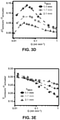
- ⁇ T sensors /T actuator (T downstream ⁇ T upstream )/T actuator for a range of Q flow from 0.01 ml min to 0.1 ml min for three anatomically relevant values of h skin , 1.1 mm (black curve), 1.7 mm (red curve) and 2.1 mm (blue curve).
- FIG. 3F .
- Ratio between signal ( ⁇ T sensors /T actuator ) and noise (standard deviation, ⁇ ) measured for Q flow 0.1 mL min over a 60 s sampling window, at a sampling frequency of 5 Hz, as a function of normalized actuator power for three different values of h skin , 1.1 mm (black curve), 1.7 mm (red curve) and 2.1 mm (blue curve).
- FIGS. 3G and 3E ( ⁇ T sensors /T actuator ) ( FIG. 3G ) and (T downstream +T upstream )/2T actuator ( FIG.
- FIG. 3E measured in the presence of phantom blood flowing through adjacent tubes in co-flow (+x) and counter-flow ( ⁇ x) configurations, for two values of h skin , 1.1 mm (black curve) and 2.1 mm (blue curve).
- FIG. 3H is a plot of the ratio of sensor to actuator temperature as a function of blood flow.
- FIGS. 3J-3K ⁇ T sensors /T actuator ) ( FIG.
- FIG. 3L In vitro experimental measurements of ⁇ T sensors /T actuator for h skin (1.1, 1.7, 2.1, and 6.0 mm for four flowrates) and for Q flow (0 ml/min (black curve), 0.05 ml/min (red curve), 0.1 ml/min (blue curve), and 0.5 ml/min (purple curve)).
- FIG. 4A-4H Wireless device, including Bluetooth communication with a portable device.
- FIG. 4B is an image of a fully assembled, integrated wireless ELA showing soft, conformal sensing/actuating components, flex-PCB (Cu/PI/Cu), and surface-mounted electronic components, including battery and wireless communication components.
- PDMS polydimethylsiloxane.
- FIG. 4C is an image of device bending, showing flexibility.
- FIG. 4D is an image of a device mounted on the skin using medical-grade, acrylate-based pressure-sensitive adhesive.
- FIG. 4E Raw sensor readout in measured bits from an 8-bit ADC during actuation and flow.
- FIG. 4F Raw sensor readout in measured bits from an 8-bit ADC during actuation and flow.
- FIG. 4G Calibration curve to measure raw 8-bit, 3-V ADC values (left) and associated voltages (right) to temperatures via calibration.
- FIG. 5A-5J Patient trials.
- FIG. 5A Exploded view illustration of ELA used in hospital setting, with elastomeric handling frame and adhesive.
- FIG. 5B Illustration (left) and image (right) of on-shunt and off shunt ELA positioning on patient, with representative Doppler ultrasound image (inset) of catheter under skin at on-shunt location.
- FIG. 5C IR images at on-shunt (top) and off shunt (bottom) indicating total local temperature rise due to actuator, and characteristic tear-drop shaped heat distribution caused by presence of flow.
- FIG. 5D Representative transient T actuator measurement on off-shunt location, and transient plane source (TPS) curve fit to yield skin thermal properties.
- FIGS. 5E-5F Representative transient T actuator measurement on off-shunt location, and transient plane source (TPS) curve fit to yield skin thermal properties.
- FIGS. 5E-5F Representative transient T actuator measurement on off-shunt location, and transient plane source (TPS) curve fit to yield skin thermal
- FIGS. 5G-5H Representative T actuator (blue curve), T upstream (black curve) and T downstream (red curve) for off-shunt location with no anisotropy ( FIG. 5G ) and on-shunt location with significant anisotropy ( FIG. 5H ).
- FIG. 5I ⁇ T sensors /T actuator measured for each patient, at off-shunt and on-shunt locations, with error bars representing SDs across a 100-sample window.
- Individual patient-level data are summarized asPatient #( ⁇ T sensors /T acuator On Shunt and ⁇ T sensors /T acuator Off Shunt): Patient 1 (0.209339 and 0.00205); Patient 2 (0.0518 and 0.0084); Patient 3 (0.09503 and ⁇ 0.00597); Patient 4 (0.100991 and 0.0061); Patient 5 (0.1392 and 0.000963).
- FIGS. 6A-6D Case study of patient with shunt malfunction.
- FIG. 6A X-Ray and radionuclide tracer showing kinking and occlusion of catheter.
- FIG. 6B Optical image of patient's peritoneal cavity immediately after surgery showing flow in repaired shunt.
- FIG. 6C X-ray and radionuclide tracer confirming working of repaired shunt.
- FIG. 6D ⁇ Tsensors/Tactuator measured by ELA before and after revision, at locations over (on) and adjacent to (off) shunt, before and after revision, confirming results from X-Ray and Radionuclide tracer.
- FIGS. 7A-7D Computation of flow rates.
- FIG. 7A FEA-computed family of curves for different skin thicknesses of ⁇ T sensors /T actuator with data measured in-vivo from each patient overlaid.
- FIG. 7B Computed curves for T sensors /T actuator for different skin thicknesses.
- FIG. 7C Computed flow rates from iteratively solving for both
- FIGS. 8A-8B Current pathways through resistive arrays.
- FIG. 8A IR image (top) and simulations of ESA with single sensor addressed, showing currents through same input line (row) and output line (column).
- FIG. 8B Same as FIG. 8A , but for a non-square array (16 ⁇ 6), showing large power dissipation through non-addressed sensors in same output line (spoke).
- FIG. 9 Schematic illustration of data acquisition and control system for 100 sensor array.
- FIG. 10 Heat map with each pixel corresponding to a residual (R 2 ) value computed for each element in 10 ⁇ 10 array from linearly fitting I meas to temperature for calibration.
- FIG. 11 Illustration of steps to convert measured current values to heat map, with steps corresponding to the images of FIG. 2D .
- Top panel Example of raw (resistance) ESA data.
- Second panel Transformation of raw ESA data to calibrated temperatures via a calibration matrix specific to each ESA.
- Third panel temperature differentials resulting from the removal of isotropic heat transfer effects from the thermal actuator via baseline subtraction.
- Bottom panel ESA temperature map obtained from temperature differential map of preceding panel by meshed bicubic interpolation.
- FIGS. 12A-12C Flow visualization and measurement from ESA.
- FIG. 12A Spatially precise schematic map of 100 sensor device with tube position overlay and upstream (U) and downstream (D) temperatures shown.
- FIG. 12B Principal components analysis (PCA) biplot (principle component 1 and 2) of baseline-subtracted differentials between a selected U sensor (two sensors, each indicated in subfigure) and each D sensor. Clustering occurs for the following cases: no flow and no actuation; no flow with actuation at 1.8 mW/mm ⁇ 2 ; Actuation at 1.8 mWmm ⁇ 2 and flow at 0.02 mL min ⁇ 1 .
- FIG. 12C PCA biplots for five (1-5) sensors (identified in FIG.
- FIGS. 13A-13C Benchtop flow system.
- FIG. 13A Optical image of benchtop flow phantom with embedded shunt.
- FIG. 13B Optical micrograph of cross section and isometric views showing catheter geometry and h skin .
- FIG. 13C Sensor laminated onto the free surface of the assembly.
- FIG. 14 Finite element simulations of dimensionless scaling parameters illustrating time evolution of heat through skin, as a measure of depth penetration, with experimentally measured numbers from the system overlaid.
- FIG. 17 Illustration of covered and uncovered (encapsulated) actuator measurements (left) to yield transient rise curves for fitting the value of H conv (right).
- FIGS. 18A-18C Illustration and experimental data showing the effect of ( FIG. 18B ) rotational and ( FIG. 18C ) translational mispositioning on measured values of ⁇ T sensors /T actuator (black curve) and T sensors /T actuator (red curve).
- FIGS. 19A-19F DC Noise sources.
- FIG. 19A Simplified schematic of data acquisition system for ELA.
- FIG. 19B Standard deviations as a function of sampling window for resistances measured by ELA (black), a commercial sensor connected via ACF cable (blue) and a commercial resistor connected via soldered lead wires (red).
- FIG. 19C Standard deviation as a function of sampling window for actuator output power.
- FIG. 19E High Frequency Noise.
- Panel A Schematic illustration of experimental system.
- Panel B Panel B.
- FIG. 19F S15. In-vivo noise
- A. Optical images illustrating no deformation (left) and extreme deformation (right) of sensor on skin.
- B-D Temperature fluctuations measured as a function of time (B), frequency (C) and as a normalized power spectral density (D) on a stationary subject.
- E-G Same as B-D on a vigorously moving subject.
- FIG. 20 Optical images of elastomeric adhesive with tape frame on wrist illustrating conformal contact during extreme deformation.
- FIGS. 21A-21B In-vivo T actuator (blue curve), T uptream (black curve) and T downstream (red curve) measurements as a function of time over on-shunt locations with low anisotropy ( FIG. 21A ) and after stimulating flow by pressing the regulating valve ( FIG. 21B ).
- FIG. 22 T actuator measurements on external ventricular drain as flow is varied by raising height of reservoir bag (not shown), thereby changing differential pressure.
- FIG. 23 Representative CT image of skin thickness over superficial catheter location over clavicle.
- FIG. 24 Schematic illustration of relevant parameters.
- FIG. 25 Flow-chart summary of flow rate determination using any of the devices described herein.
- FIG. 26 Illustration of carrier and handling layer, with the device peeled back and away from the rigid handling layer of glass.
- FIG. 27 Skin-safe, silicone adhesive, with active sensing portion of device able to maintain conformal contact with skin, with delamination confined to edge handling substrate that surrounds the active sensing portion.
- FIG. 28 Another illustration showing the handling substrate with an opening where the active sensing portion of device may be positioned.
- FIG. 29 provides an overview of the sensing platform technology, including hardware and software.
- FIG. 30 illustrates an example sensor design for commercial, surface mounted temperature sensors.
- FIG. 31 provides an example of a flexible printed circuit board (PCT) based flow sensor including thermal actuation by an array of resistive elements.
- PCT printed circuit board
- FIG. 32 provides an analog design of circuits described herein.
- FIG. 33 illustrates the use of thermochromatic dyes arranged in an array to determine subdermal fluid flow.
- FIG. 34 provides an example of a thermal imaging approach and currently available inexpensive thermal imaging devices.
- FIG. 35 provides an example of in vitro testing of a surface-mount device ad described herein without foam insulation.
- FIG. 36 provides an example of in vitro testing of a surface-mount device ad described herein with a foam insulation layer, illustrating the increase in signal to noise ratio provided by insulation.
- FIG. 37 provides in vitro testing of a surface-mount device with foam insulation across flow rates and relevant skin thicknesses, including a discontinuous thermally conductive layer positioned proximate to the thermal actuator and sensors.
- FIG. 38 provides an example sensor integrated with packaging and encapsulation for thermal insulation.
- FIG. 39 shows an example device with encapsulation removed to expose and illustrate the various components as described herein.
- FIG. 40 provides both benchtop and on-body sensing results of an example device.
- FIG. 41 illustrates the ability of a sensing device to measure change in temperature when positioned over a shunt as an in vivo example.
- FIG. 42 illustrates the use of a device with multiple sensors and provides an example circuit diagram.
- FIG. 43 illustrates the increase in rotational tolerance for 4-sensor device.
- FIG. 44 illustrates the increase in translational tolerance for 4-sensor device.
- FIG. 45 provides example hardware for wireless, inductive power coupling for recharging and BLE wake-up.
- FIG. 46 provides an example software interface.
- FIG. 47 provides a summary of clinical results.
- FIG. 48 provides an example of a clinical protocol that may be useful to ensure accurate application of the devices described herein.
- FIG. 49 provides an example of a clinical checklist that may be useful to ensure accurate application of the devices described herein.
- FIG. 50 provides an example schematic of a device as described herein utilizing an array of resistors to provide thermal actuation.
- FIG. 51 provides an example cross-sectional schematic of a device incorporating an insulating layer and a discontinuous thermally conductive layer.
- FIGS. 52A-52C illustrate the effect of altered intersensor distances (L).
- FIG. 52A is a schematic illustration showing positions of actuator and upstream and downstream temperature sensors relative to underlying catheter.
- FIG. 52A is a schematic illustration showing positions of actuator and upstream and downstream temperature sensors relative to underlying catheter.
- FIG. 52A is a schematic illustration showing positions of actuator and upstream
- FIGS. 53A-53D Miniaturized, soft wireless flow sensor based on commercial components.
- FIG. 53A Exploded view schematic of key device layers.
- FIG. 53B Optical images of packaged, encapsulated device twisting and bending.
- FIG. 53C Optical image of device mounted on neck of patient.
- FIG. 53D Screenshot of software application on tablet computer showing data readout, pairing and options for on-demand thermal actuation.
- FIGS. 54A-54F Benchtop flow characterization using platform.
- FIG. 54A Exploded view schematic of sensors and actuators with overlaid foam layer over shunt embedded in silicone skin phantom.
- FIG. 54B Infrared (IR) thermograph of actuator dissipating thermal power at 1.2 mW/mm 2 .
- FIG. 54C Upstream (gray) and downstream (red) temperature readout after actuation, and after during flow respectively, showing the bifurcation of the traces ( ⁇ T) and the reduced overall average temperature (T avg ), respectively, after the onset of flow.
- FIG. 54D ⁇ T as a function of time before and after the onset of flow.
- FIG. 54E .
- ⁇ T as a function of flow rate for a range of physiologically relevant skin thicknesses, from 0.7 mm to 4 mm.
- FIG. 54F T avg as a function of flow rate for a range of physiologically relevant skin thicknesses.
- FIGS. 55A-55B Patient studies on adults.
- FIG. 55A Optical image of wireless sensor over shunt on representative patient, without smartphone readout.
- FIG. 55B ⁇ T for cases with confirmed flow, no flow/irregular flow and off shunt locations, with error bars representing S.D.
- FIG. 56 Spatial and Temporal Precision of negative temperature coefficient temperature sensors (NTCs).
- FIG. 57 Stability of temperature sensors, with measured temperature from two temperature sensors as a function of time.
- FIG. 58 Unpackaged circuit layout providing various electronic components on-board the device, including for power, wireless communication and circuitry to control and measure.
- FIG. 59 Analog front end and wireless temperature sensing precision.
- the temperature sensors show high linearity over a range of biologically-relevant skin temperatures.
- FIGS. 60A-60D Power-saving switch feature.
- FIG. 61 Molding and packaging process that can be used to make any of the devices of the instant invention.
- FIG. 62 Device configured to have rotational tolerance by a 4-sensor device.
- the plots are for a device aligned and for various rotations of 22.5, 45 and 90 degree rotation.
- FIG. 63 Device configured to have translational tolerance by a 4-sensor device.
- the plots are for a device aligned and for various translational offsets of 2 mm, 5 mm and complete misalignment.
- FIG. 64 Effect of foam insulation on temperature sensors.
- FIG. 65 Applicability to blood vessels, with the left panels for a device that is not over a blood vessel and the right panels for a device over a vein.
- FIG. 66 Representative clinical images of a device positioned on and off shunt.
- FIG. 67 Schematic illustration of a device.
- Soft refers to a material that may be comfortably positioned against the skin without discomfort or irritation to the underlying skin by the material itself deforming to conform to the skin without unduly exerting force on the underlying skin with corresponding device-generated skin deformation. Softness/hardness may be optionally quantified, such as in terms of durometer, or a material's resistance to deformation.
- the substrate may be characterized in terms of a Shore 00 hardness scale, such as a Shore 00 that is less than 80.
- Soft may also be characterized in terms of a modulus, such as a Young's modulus that is less than or equal to 100 kPa.
- “Stretchable” refers to a material's ability to undergo reversible deformation under an applied strain. This may be characterized by a Young's modulus (stress/strain).
- a bulk or effective Young's modulus refers to a composite material formed from materials having different Young's modulus, so that the bulk or effective Young's modulus is influenced by each of the different materials and provides an overall device-level modulus.
- “Flexible” refers to a material's ability to undergo a bending with fracture or permanent deformation, and may be described in terms of a bending modulus.
- any of the devices may be described herein as being “mechanically matched” to skin, specifically the skin over which the device will rest.
- This matching of device to skin refers to a conformable interface, for example, useful for establishing conformal contact with the surface of the tissue.
- Devices and methods may incorporate mechanically functional substrates comprising soft materials, for example exhibiting flexibility and/or stretchability, such as polymeric and/or elastomeric materials.
- a mechanically matched substrate may have a modulus less than or equal to 100 MPa, less than or equal to 10 MPa, less than or equal to 1 MPa.
- a mechanically matched substrate may have a thickness less than or equal to 0.5 mm, and optionally for some embodiments, less than or equal to 1 cm, and optionally for some embodiments, less than or equal to 3 mm.
- a mechanically matched substrate may have a bending stiffness less than or equal to 1 nN m, optionally less than or equal to 0.5 nN m.
- a mechanically matched device, and more particularly a substrate is characterized by one or more mechanical properties and/or physical properties that are within a specified factor of the same parameter for an epidermal layer of the skin, such as a factor of 10 or a factor of 2.
- a substrate may have a Young's Modulus or thickness that is within a factor of 20, or optionally for some applications within a factor of 10, or optionally for some applications within a factor of 2, of a tissue, such as an epidermal layer of the skin, at the interface with a device of the present invention.
- a mechanically matched substrate may have a mass or modulus that is equal to or lower than that of skin.
- Encapsulate refers to the orientation of one structure such that it is at least partially, and in some cases completely, surrounded by one or more other structures, such as a substrate, adhesive layer or encapsulating layer. “Partially encapsulated” refers to the orientation of one structure such that it is partially surrounded by one or more other structures, for example, wherein 30%, or optionally 50%, or optionally 90% of the external surface of the structure is surrounded by one or more structures. “Completely encapsulated” refers to the orientation of one structure such that it is completely surrounded by one or more other structures.
- Polymer refers to a macromolecule composed of repeating structural units connected by covalent chemical bonds or the polymerization product of one or more monomers, often characterized by a high molecular weight.
- the term polymer includes homopolymers, or polymers consisting essentially of a single repeating monomer subunit.
- the term polymer also includes copolymers, or polymers consisting essentially of two or more monomer subunits, such as random, block, alternating, segmented, grafted, tapered and other copolymers.
- Useful polymers include organic polymers or inorganic polymers that may be in amorphous, semi-amorphous, crystalline or partially crystalline states. Crosslinked polymers having linked monomer chains are particularly useful for some applications.
- Polymers useable in the methods, devices and components disclosed include, but are not limited to, plastics, elastomers, thermoplastic elastomers, elastoplastics, thermoplastics and acrylates.
- Exemplary polymers include, but are not limited to, acetal polymers, biodegradable polymers, cellulosic polymers, fluoropolymers, nylons, polyacrylonitrile polymers, polyimide-imide polymers, polyimides, polyarylates, polybenzimidazole, polybutylene, polycarbonate, polyesters, polyetherimide, polyethylene, polyethylene copolymers and modified polyethylenes, polyketones, poly(methyl methacrylate), polymethylpentene, polyphenylene oxides and polyphenylene sulfides, polyphthalamide, polypropylene, polyurethanes, styrenic resins, sulfone-based resins, vinyl-based resins, rubber (including natural rubber, styrene-butad
- Eastomer refers to a polymeric material which can be stretched or deformed and returned to its original shape without substantial permanent deformation. Elastomers commonly undergo substantially elastic deformations. Useful elastomers include those comprising polymers, copolymers, composite materials or mixtures of polymers and copolymers. Elastomeric layer refers to a layer comprising at least one elastomer. Elastomeric layers may also include dopants and other non-elastomeric materials.
- Useful elastomers include, but are not limited to, thermoplastic elastomers, styrenic materials, olefinic materials, polyolefin, polyurethane thermoplastic elastomers, polyamides, synthetic rubbers, PDMS, polybutadiene, polyisobutylene, poly(styrene-butadiene-styrene), polyurethanes, polychloroprene and silicones.
- Exemplary elastomers include, but are not limited to silicon containing polymers such as polysiloxanes including poly(dimethyl siloxane) (i.e.
- PDMS and h-PDMS poly(methyl siloxane), partially alkylated poly(methyl siloxane), poly(alkyl methyl siloxane) and poly(phenyl methyl siloxane), silicon modified elastomers, thermoplastic elastomers, styrenic materials, olefinic materials, polyolefin, polyurethane thermoplastic elastomers, polyam ides, synthetic rubbers, polyisobutylene, poly(styrene-butadiene-styrene), polyurethanes, polychloroprene and silicones.
- a polymer is an elastomer.
- Conformable refers to a device, material or substrate which has a bending stiffness that is sufficiently low to allow the device, material or substrate to adopt any desired contour profile, for example a contour profile allowing for conformal contact with a surface having a pattern of relief features.
- a desired contour profile is that of skin.
- Conformal contact refers to contact established between a device and a receiving surface, specifically skin.
- conformal contact involves a macroscopic adaptation of one or more surfaces (e.g., contact surfaces) of a device to the overall shape of a surface.
- conformal contact involves a microscopic adaptation of one or more surfaces (e.g., contact surfaces) of a device to a surface resulting in an intimate contact substantially free of voids.
- conformal contact involves adaptation of a contact surface(s) of the device to a receiving surface(s) such that intimate contact is achieved, for example, wherein less than 20% of the surface area of a contact surface of the device does not physically contact the receiving surface, or optionally less than 10% of a contact surface of the device does not physically contact the receiving surface, or optionally less than 5% of a contact surface of the device does not physically contact the receiving surface.
- Devices of certain aspects are capable of establishing conformal contact with internal and external tissue.
- Devices of certain aspects are capable of establishing conformal contact with tissue surfaces characterized by a range of surface morphologies including planar, curved, contoured, macro-featured and micro-featured surfaces and any combination of these.
- Devices of certain aspects are capable of establishing conformal contact with tissue surfaces corresponding to tissue undergoing movement.
- Young's modulus is a mechanical property of a material, device or layer which refers to the ratio of stress to strain for a given substance. Young's modulus may be provided by the expression:
- E Young's modulus
- L 0 the equilibrium length
- ⁇ L the length change under the applied stress
- F the force applied
- A the area over which the force is applied.
- Young's modulus may also be expressed in terms of Lame constants via the equation:
- Low modulus refers to materials having a Young's modulus less than or equal to 10 MPa, less than or equal to 5 MPa or less than or equal to 1 MPa.
- Bending stiffness is a mechanical property of a material, device or layer describing the resistance of the material, device or layer to an applied bending moment. Generally, bending stiffness is defined as the product of the modulus and area moment of inertia of the material, device or layer. A material having an inhomogeneous bending stiffness may optionally be described in terms of a “bulk” or “average” bending stiffness for the entire layer of material.
- Thermal actuation state refers to the thermal actuator that is on an off-state or an on-state.
- substantially independent refers to a position of the reference sensor that is sufficiently separated from the actuator that the reference sensor output is independent of whether the thermal actuator is on or off.
- the systems and methods presented herein are compatible with relatively minor effects of the actuator on the reference sensor, such as within 5%, within 1% or within 0.1% of a reference temperature when the actuator is in the on state compared to when the actuator is in the off state. Depending on specific device and tissue characteristics, this distance may be between about 10 mm and 20 mm, such as about 15 mm.
- a conformable device 10 to measure subdermal fluid flow may comprise a substrate 20 that supports upstream 30 and downstream 40 temperature sensors. Upstream and downstream are described relative to flow direction in the fluid conduit.
- the temperature sensors may be part of an array of temperature sensors, including a high density array 300 as shown in FIG. 1A-1B . Within that array, are any number of reference sensors used to assess one or more baseline skin properties, including an actuator reference sensor 60 and/or ambient reference sensor 80 .
- the reference sensor locations may be determined to be those that are independent of thermal actuation status (e.g., ambient reference sensor) or of flow status in the conduit (e.g., actuator reference sensor).
- the reference sensor locations may be characterized in terms of a separation distance ( 65 85 ) from notional line 70 that is a straight line connection between the upstream and downstream temperature sensors and the thermal actuator to the reference sensors ( 60 80 ) ( FIG. 67 ).
- a microprocessor 160 may be wirelessly connected via one or more wireless communication components 310 to the temperature sensors and/or to connect the device 10 to a microcontroller 320 illustrated as within a hand-held or computer 330 remote device.
- a power source 150 (also illustrated as 350 in FIG. 4B ) may be connected on-board device 10 .
- the power source may correspond to wirelessly charging components.
- Wireless communication components 5810 are also illustrated in FIG. 58 (see also antenna of FIG. 4B ).
- the device may be covered with an encapsulation layer 1700 ( FIG. 17 ), including a foam layer or an additional partial layer formed of foam on top of the encapsulating layer (also referred herein as a superstrate—see, e.g., FIG. 53A ) positioned to vertically cover the temperature actuator and sensors.
- an encapsulation layer 1700 FIG. 17
- any of the devices provided herein may comprise a foam layer positioned over an encapsulation layer, wherein the foam layer may cover the entire encapsulation layer or a portion thereof that corresponds, in a vertical geometrical configuration, to the temperature sensors and actuator to minimize thermal noise and improve device performance and sensitivity.
- FIG. 46 illustrates a device operably integrated or connected to a computer-implemented program or application 4600 having an on-demand actuation 4610 on a handheld.
- a computer-implemented program or application 4600 having an on-demand actuation 4610 on a handheld.
- individual sensor control, device actuation, and date monitoring is readily, conveniently and reliably available to a medical professional who may be remotely located from a patient who is wearing the device.
- Example 1 Epidermal Electronics for the Noninvasive, Wireless, Quantitative Assessment of Ventricular Shunt Function
- Ventricular shunts represent an essential component of clinical treatment for hydrocephalus, a common and debilitating neurological disorder that results from the overproduction and/or impaired reabsorption of cerebrospinal fluid (CSF) produced in the ventricular system of the brain [Rachel].
- Hydrocephalus arises from a number of causes, including but not limited to cancer, hemorrhage, trauma, and congenital malformations. This condition affects an estimated 750,000 patients in the United States alone, and it is responsible for ⁇ 3.1% of all pediatric acute care costs [Lam, Patwardhan, Shannon, Stone]. 125,000 pediatric hydrocephalus patients in the US account for 400,000 days spent in the hospital each year [Simon].
- Shunts assemblies typically involve two silicone catheters, connected upstream and downstream of a regulating valve, to drain excess CSF from the ventricle to a distal absorptive site, usually the peritoneum, pleura, or right atrium of the heart. While effective in CSF diversion and prevention of the sequelae of hydrocephalus, including seizures, coma, neurological injury and death, shunts are highly prone to failure [Tervonen] due to fibrinous catheter ingrowth, kinking, discontinuity, over-drainage, distal malabsorption and infection [Garton, Yuh]. An estimated 84.5% shunt recipients require revision operations [Cochrane, Shah, Stone, Piatt].
- CT computerized tomography
- X-Ray plain films
- MRI magnetic resonance imaging
- RSPS radionuclide shunt patency studies
- ShuntCheck shunt aspiration
- ShuntCheck flow monitoring systems
- This example presents a simple, non-invasive sensor platform that provides a low-cost, comfortable means for quantitatively assessing flow through cerebrospinal shunts.
- the platform exploits advances in materials, mechanics and fabrication schemes that serve as the foundations for a class of electronics that is ultrathin ( ⁇ 100 ⁇ m), soft (Young's modulus, E ⁇ 70 kPa), lightweight (area mass density, ⁇ 10 mg/cm 2 ) and skin-like it is physical properties, with resulting flexural rigidities that are nine orders of magnitude lower than those of traditional, rigid sensors.
- Such ‘epidermal’ electronic systems support broad classes of measurement capabilities that offer clinical grade accuracy in capturing body kinematics[1] electrophysiological signals [2,3], soft tissue mechanical properties [4] chemical markers in sweat [5,6] and many others.
- Multimodal thermal characterization is also possible, owing to the exceptionally low thermal masses ( ⁇ 10 mJ cm ⁇ 2 K ⁇ 1 ), fast response times ( ⁇ 10 ms), and exceptional precision in temperature measurements ( ⁇ 20 mK) of these platforms and to their ability for controlled delivery of thermal power to underlying tissue [7-11].
- Specific embodiments allow for high resolution skin thermography and for precise measurements of the thermal conductivity and the thermal diffusivity of the skin.
- Recent work [12] also illustrates the possibility of quantifying macrovascular blood flow based on measurements of spatial anisotropies in thermal transport.
- the results represent a breakthrough in hydrocephalus diagnostics, with ability to visualize flow in a simple, user-friendly mode, accessible to the physician and patient alike.
- Systematic benchtop evaluations, thermographic imaging and finite element analysis (FEA) of the physics of heat transport reveal the effects of skin thermal properties and thickness, as well as device and catheter geometries. The results establish considerations in design for a range of practical operating conditions.
- An integrated wireless system allows for recording and transmission of data to standard consumer devices such as smartphones and tablet computers. Trials on five adult shunt recipients with a diverse range of etiologies, and comparisons with CT, MRI and radionuclide tracing validate device function in-vivo, and advanced processing algorithms for quantitative determination of flow rates.
- Dense arrays for flow visualization The feasibility of using arrays of epidermal temperature sensors and thermal actuators to quantify anisotropies in thermal transport through the skin induced by macrovascular blood flow has been demonstrated [10,12].
- the device architectures and fabrication schemes shown here increase the number of sensors by nearly a factor of ten relative to this past work, and the density of these elements by a factor of four, using clusters distributed around a central thermal actuator, to provide levels of precision and spatial resolution necessary for characterizing flow through shunts.
- a schematic illustration of this platform (epidermal sensing array, ESA) appears in FIG. 1A .
- Optical micrographs of the key features are in FIG. 1B .
- Two layers of metallic traces (Ti/Cu/Ti/Au 20/600/20/25 nm) patterned in serpentine geometries define interconnects between the sensing and actuating elements, with polyimide (PI) as an interlayer dielectric.
- PI polyimide
- a film of PI (9 ⁇ m total thickness) patterned and aligned to the metal features serves as an encapsulation layer.
- a soft (70 kPa) substrate such as an elastomeric substrate (Ecoflex, 100 ⁇ m) serves as a support. Connecting unique combinations of rows (to supply a sensing voltage, V sup ) and columns (to measure a resulting current, I meas ) enables individual addressing of each element in the array, as in FIG. 2C . Operation of the thermal actuator, as seen in the IR thermograph in FIG. 2C , results in a spatio-temporal pattern of temperatures that can be captured by high-speed, automated interrogation of the sensors in the array. An illustration of the data acquisition system appears in FIG. 9 .
- FIGS. 8A-8B Arrays in square geometries, with an equal number of input and output lines (10 ⁇ 10 for the case illustrated here) mitigate effects of parasitic current pathways.
- FIGS. 8A-8B Theoretical and experimental comparisons of current distributions in square and non-square arrays appear in FIGS. 8A-8B .
- the ease of fabrication and robustness of operation of metallic resistive sensor elements make them attractive options compared to semiconductor devices, composite organic thermistors and others.
- the series of images in FIG. 2E illustrates the mechanical compliance and physical robustness of these systems.
- the current I meas that passes through a sensor for a given applied potential defines a resistance that can be converted to temperature via a linear calibration factor, whose goodness of fit is illustrated in FIG. 10 .
- the effects of directional flow through a small diameter tube underlying the device can be seen in the IR thermographs of FIG. 2F .
- thermal transport occurs most effectively along the direction of flow, thereby creating a pronounced anisotropy in the temperature distribution, with a magnitude that can be quantitatively related to the volumetric flow rate, as discussed subsequently.
- the layout of the sensing elements allows accurate measurements of this anisotropy for cases relevant to flow through subcutaneous shunts with typical dimensions.
- the high-density platforms introduced here (1) obviate the need for perfect alignment with the underlying ventricular shunt, (2) facilitate the use of image processing techniques to visualize flow fields, and (3) allow for statistical approaches to interpreting flow due to the density of information.
- the schematic illustration in FIG. 2A identifies a set of 50 sensors upstream (T upstream ) and downstream (T downstream ) of the thermal actuator. Subtracting T upstream from T downstream for each physically-matched piecewise sensor pair (indicated by the paired colors in FIG. 2A ) yields temperature differentials ( ⁇ T sensor ) that measure the degree of thermal anisotropy that results from fluid flow. As shown in FIG. 2B , ⁇ T sensors for sensor pairs A and B that directly overlay a catheter exhibit strong thermal anisotropy under two different flow conditions (0.02 mL min ⁇ 1 , 0.2 mL min ⁇ 1 ) within an established range for CSF flow[13].
- Sensor location B displays a higher sensitivity to flow than location A due to the reduced effect of direct thermal conduction from the actuator, relative to anisotropic thermal transport due to fluid flow.
- Measurements of ⁇ T for distal sensor pairs orthogonal to the flow direction show weak anisotropy (C) while distal pairs parallel to flow direction (D) show an absence of flow-induced thermal anisotropy. This orientation dependence obviates the requirement for precise sensor alignment to tube direction due to the ESA sensor density and cardinal symmetry.
- PCA Principle Component Analysis
- the PCA model constructed from a time-series ESA measurement, uses ⁇ T PCA values to calculate the principle components (PC).
- ⁇ T PCA T downstream ⁇ T upstream,i , where T downstream is the temperature matrix of all downstream sensors (1-50) and T upstream,i is the temperature for a single (i) upstream sensor.
- the first two components (PC1, PC2) describe approximately 92% of the overall variability of the data (70.5% PC1, 22.1% PC2) with the remainder (8% across PC3:PC50) associated with noise.
- FIG. 2C shows projections of each ⁇ T PCA for two selected T upstream,i sensors (Top—orthogonal, distal sensor in red; Bottom—inline, distal sensor in red) at each measurement in an ESA time-series (same as FIG. 2B ) in two dimensions using the first two principle components.
- FIG. 2C reveals data clustering (95% confidence ellipses) corresponding to three experimental conditions: absence of fluid flow without thermal actuation (flow off/heat off), absence of flow with thermal actuation (flow off/heat on), and fluid flow with thermal actuation with separate clusters for different flow regimes (0.02 mL min ⁇ 1 , 0.2 mL min ⁇ 1 ).
- these clusters are independent of the selected Tui sensor (additional biplots shown in FIGS. 12A-12B ).
- a comparison of the data clusters and principal components shows that PC1 primarily relates to the degree of thermal actuation while PC2 relates to the presence or absence of flow. Mapping the variables to the PCA biplot indicates sensor correlation to fluid flow.
- FIG. 2C an overlay of four variable factors corresponding to T D sensors known to be proximal (red) and distal (blue) to fluid flow shows the positive correlation for the proximal sensors and negative correlation for the distal sensors to fluid flow for both orthogonal and inline T upstream,i sensors.
- PCA offers a strategy to mitigate effects of ESA misalignment by determining the T upstream,i sensor that yields the maximal separation between no flow/flow data clusters (along the PC2 axis). As observed in FIG. 2C , the inline T upstream,i sensor strongly separates these cluster groups as compared to the orthogonal T upstream,i sensor. In this manner, for scenarios without a priori orientation, PCA offers a straightforward means for evaluating correlations between T upstream,i and flow state and, therefore, orientation of the catheter relative to the ESA.
- the density of the ESA enables spatial mapping of the temperature anisotropy that results from fluid flow. These maps result from the processing of raw measurements from the ESA as outlined in FIG. 2D .
- the temperature values can be mapped to the physical spatial coordinates of each sensor on a simulated square “pixel” array larger than the ESA (grid: 17 mm ⁇ 17 mm, 10 px mm ⁇ 1 ) resulting in a 170 ⁇ 170 ⁇ N matrix for a time-series measurement of N frames.
- T normalized results from the subtraction of the background temperature T background from each frame.
- T actuator isotropic heat transfer temperatures
- FIG. 2D compares the ESA temperature maps with IR thermographs (same scale) in the absence (left) and presence (right) of flow (0.02 mL min ⁇ 1 ). As seen via the sensor overlay in each image, the high density of the ESA enables good fidelity in visualizing the thermal anisotropy over the embedded catheter.
- FIGS. 13A-13C With optical images of a representative system appearing in FIGS. 13A-13C .
- Operating the actuator at a controlled, low-power (1.35 mW/mm 2 ) level creates heat that diffuses through the silicone skin phantom (silicone) at a rate governed by the thermal diffusivity of this material, ⁇ skin .
- a scaling law that graphically illustrates the depth of penetration of this thermal field into the phantom appears in FIG. 14 .
- the phantom can be treated as a semi-infinite solid[14], which approaches a quasi-steady state equilibrium over relatively long ( ⁇ 400 s) times with a corresponding penetration depth of ⁇ 5 mm.
- Typical ventricular catheters are implanted subdermally, at depths of 1-2 mm [15], well within the range of detectability.
- Q CSF 0
- thermal transport from the actuator occurs equally in the ⁇ Tx, ⁇ Ty and ⁇ z directions, resulting in equal values for ⁇ T upstream , and ⁇ T downstream . This regime appears in the unshaded portion of FIG. 3B .
- the fluid serves to transport heat from the actuator preferentially to the downstream sensor, and away from the upstream sensor, resulting in a measured increase in ⁇ T downstream , and decrease in ⁇ T upstream , as seen in the blue shaded region in FIG. 3B .
- the convective effects of the fluid dominate, leading to a net cooling effect on both sensors, but at different rates, with ⁇ T upstream equilibrating at a lower value than ⁇ T downstream as seen in the red and black shaded regions in FIG. 3B .
- the actuator is convectively cooled by the fluid at a rate governed by the magnitude of the flow, resulting in reductions of ⁇ T actuator , in the presence of flow as shown by the blue curve in FIG. 3B .
- T upstream /T actuator and T upstream /T actuator show for a complete range of physiologically relevant values of Q CSF in FIG. 3C .
- the non-monotonic effects of flow for different skin thicknesses (h skin ) increase and decrease when considering the difference between the sensors ( ⁇ T sensors /T actuator ) and their average ( T sensors /T actuator ), respectively, as shown in FIGS. 3D-3E .
- ⁇ T sensors /T actuator and T sensors /T actuator are measures of thermal anisotropy and flow magnitude, respectively. Taken together, these quantities allow for determination of flow rate, and can be used to distinguish degenerate points on either side of the peak values shown in FIG. 3D .
- h skin represents an important geometric parameter. As shown in FIGS. 3D-3E , increasing h skin decreases the effects of flow on the sensor responses, simply due to the finite depth of penetration of the thermal field. Although transient techniques can be used to determine h skin from thermal measurements, as shown in FIG. 15 , in practice, h skin can be measured directly using CT and Doppler ultrasound, as discussed subsequently.
- the power/area of the actuator represents an important design consideration. Increasing P actuator improves the signal to noise ratio (S/N) of the measurements, but biological considerations set an upper limit for non-invasive use.
- S/N signal to noise ratio
- the effects of P actuator on S/N appear in FIG. 3F , where the signal is an averaged measurement over 60 s (measured at 5 Hz) of ⁇ T sensors /T actuator for a flow rate of 0.13 mL min ⁇ 1 .
- the noise is the standard deviation ( ⁇ 60s ) computed to three significant digits.
- P actuator >1 mW/mm 2
- the advantages of increased actuation power diminish, and the noise stabilizes at 2% of the measured signal.
- the increase in local temperature varies linearly with P actuator at a rate of 6.01 K (mW mm ⁇ 2 ) ⁇ 1 on PDMS (Sylgard 184), as shown in FIG. 16 .
- a possible confounding effect for the measurement follows from blood flow through superficial veins, as shown in a benchtop model in FIGS. 3G-3H , for two skin thicknesses and in two configurations: flow aligned with (+x, co-flow) and opposite to ( ⁇ x, counter-flow) flow of CSF flow, for rates at the upper end of the range typically encountered in veins located near the surface of the skin of the neck.
- co-flow represents the most realistic case, as venous blood flow typically proceeds from the brain towards the heart. Arterial flow can be neglected since its depth (>1 cm) occurs below the limit of detectability for the sensors reported here.
- the thermal conductivity (k skin ) and diffusivity ( ⁇ skin ) of skin also represent unknowns, with human skin exhibiting a range of 0.2 W m ⁇ 1 K ⁇ 1 ⁇ k skin ⁇ 0.45 W m ⁇ 1 K ⁇ 1 and 0.9 mm 2 s ⁇ 1 ⁇ skin ⁇ 0.17 mm 2 s ⁇ 1 [11].
- Phantom skins with properties that bound this range can be constructed from silicone materials with two different formulations (Sylgard 170 and Sylgard 184, Dow Corning, Inc.). Measurements of the thermal properties of these materials ( FIG.
- Systems provided herein are compatible with wireless data acquisition, including via Bluetooth. This represents an important patient care aspect, as the patient need not be hard-wired to any instruments. In this manner, continued monitoring is possible without confining patient location or motion.
- FIG. 5A A schematic illustration of the resulting embodiment appears in FIG. 5A , showing the ELA and ultrathin elastomer substrate (100 ⁇ m, Ecoflex+MG7 1010 Adhesive) supported by an elastomeric frame (2 mm, Sylgard 170).
- FIG. 5B schematically illustrates the on-shunt and off-shunt location. Locating the catheter under the skin via touch was facile, and precise positioning was achieved with Doppler ultrasound (Sonosite Inc., Bellevue Wash.). A representative Doppler image of the catheter appears in FIG. 5B (inset).
- Linear markings on the device allow for easily alignment of the central axis of the actuator and sensors with the underlying shunt. Although the shunt is not visible under the skin, its ends can be easily aligned to the markings on the device via touch.
- Low-power actuation (1.3 mW/mm 2 ) ensures maximum temperature increases of ⁇ 5° C., as confirmed by IR images in FIG. 5C . These values are well below the threshold for sensation, in accordance with IRB-approved protocols.
- Markers in FIG. 5B identify mounting locations in FIG. 5C . The results show a characteristic tear-drop distribution of temperature, consistent with flow.
- Transient, off-shunt measurements of T actuator define the thermal transport properties of the patient's skin.
- a representative response before, during and after actuation appear in FIG. 5D .
- Values of k skin and ⁇ skin extracted from these data appear in FIGS. 5E-5F ; the magnitudes are comparable to those expected for skin [11].
- Data from the flow sensor are in FIGS. 5G-5H , where the red, black and blue curves represent the temperatures measured from the upstream sensor, the downstream sensor, and the actuator, respectively.
- Locations adjacent to the shunt that are free of near-surface blood vessels present no sources of thermal anisotropy and, therefore, can serve as control measurements.
- Results from a representative case are in FIG. 5G , where the upstream and downstream responses are nearly identical.
- FIG. 5H Anisotropy that results from flow through a shunt appears in FIG. 5H .
- the presence or absence of flow corresponding to shunt functioning or failure can be immediately determined simply by observing the presence or absence of thermal anisotropy.
- Measured values of ⁇ T sensors /T actuator appear in FIG. 5I for on-shunt and off-shunt locations for all 5 patients.
- Anisotropy appears clearly for all working shunts. Error bars correspond to standard deviations computed over 100 samples.
- FIG. 6A corresponds to a patient (F, 36) with a shunt malfunction suspected to be due to a kink in the distal catheter, and later confirmed by the X-Ray and Radionuclide Tracer (RT) images.
- Surgical intervention relieved the kink, causing a dramatic, visible increase in flow, as shown in the optical image in FIG. 6B .
- the continuous presence of flow was further confirmed via post-operative X-Ray and RT, revealing a straightened distal catheter and a clear trace beyond the valve, as shown in FIG. 6C .
- the quantitative extraction of flow rates from such data can be accomplished via fitting to FEA models that use measurements of k skin and ⁇ skin , ⁇ T sensors /T actuator and T sensors /T actuator and a priori knowledge of the inner and outer diameters of the catheter, and its thermal properties k catheter and ⁇ catheter . Placing the sensor at distal catheter locations that are determined, via touch, to be the most superficial maximizes the precision of the measurement. Analysis of CT and Doppler ultrasound images, such as the ones shown in FIG. 5B and FIG. 23 define h skin at these locations to be 1.5 mm ⁇ 0.1 mm.
- FEA yields computed curves for T sensors /T actuator and ⁇ T sensors /T actuator for a 0.01 ml min ⁇ 1 ⁇ Q CSF ⁇ 1 ml min ⁇ 1 .
- measured values of T sensors /T actuator define regimes of flow, i.e. high-flow (Q>0.05 mL min ⁇ 1 ) or low-flow (Q ⁇ 0.05 mL min ⁇ 1 ).
- values of T sensors /T actuator >0.29 represent low-flow
- T sensors /T actuator ⁇ 0.29 represent high-flow for all skin thicknesses, as shown in FIG. 7B .
- Measured values of T sensors /T actuator and ⁇ T sensors /T actuator are then iteratively fitted to yield a unique flow rate. Following this process for our measured data yields quantitative flow values.
- a commercially available sensor offers an alternative to imaging-based diagnostic tools[18-21].
- the system comprises a cooling pack that is held against the skin over the distal catheter, with conventional, bulk temperature sensors attached to the skin downstream, along the direction of the catheter.
- the pack cools flowing CSF, thereby decreasing the temperature of the downstream sensor.
- this system has high specificity ( ⁇ 100%)[20] and sensitivity (80%), it suffers from key limitations.
- the embodiment is bulky and offers a poorly coupled sensor-skin interface that demands the use of a large pack (2.5 cm ⁇ 2.5 cm) and significant cooling. This requirement, together with a conventional, large-scale data acquisition (DAQ) system, decreases the usability of the system and prevents continuous, long-term measurements.
- DAQ large-scale data acquisition
- the measurements are semi-quantitative, without an ability to account for key factors such as skin thickness, skin thermal properties and device layout. Taken together, these factors lead to overall patient discomfort and prevent straightforward interpretation of data[20].
- a comparison of existing diagnostic techniques is in FIG. 16 .
- wireless capabilities allow ventricular shunts to be monitored telemetrically, with mobile application development aiding clinical assessment for treating physicians.
- precision measurements and seamless wireless transmission will provide an economically practical, clinically effective tool for the clinician.
- the psychological burden of non-specific symptoms creates significant anxiety for patients, families and caregivers.
- a sensor platform of the type introduced here can be employed in at-home diagnostics, mitigating uncertainty.
- NPH normal pressure hydrocephalus
- IIH idiopathic intracranial hypertension
- slit-ventricle syndrome a condition in which abnormal pressure hydrocephalus (NPH) causes tremendous suffering for affected patients.
- NPH characterized by a triad of neuropsychiatric changes, urinary incontinence, and gait imbalance, may affect up to 20 million (typically elderly) individuals annually.
- the associated pathophysiology may be related to choroid villous malabsorption, and overdrainage in these individuals may cause venous rupture and subdural hematoma, often necessitating neurosurgical intervention [Kameda, Lesniak].
- Fabrication of the sensor system For the sensors presented here, fabrication began with spin-casting a sacrificial layer of poly(methyl methacrylate) (700 nm) onto a 4′′, undoped Si-wafer. A dielectric layer, polyimide (PI, 3 ⁇ m) is then spun on. For the epidermal linear array (ELA), a single bilayer film of Cr/Au 10/100 nm deposited by electron-beam evaporation onto the wafer, and patterned by photolithography and etching formed the sensors and serpentine interconnects, in accordance with design rules in stretchable electronics [22-25].
- ELA epidermal linear array
- a bilayer film of Cr/Au 10/100 nm was photolithographically defined to form 100 resistive temperature sensing elements, arranged in a 10 ⁇ 10 array, around a central resistive thermal actuator.
- a multilayer film of Ti/Cu/Ti/Au 20/600/20/25 nm evaporated and photolithographically defined yielded a first layer of rows of serpentine interconnects to address each row of sensors.
- spin-casting defined a final layer of PI layer (3 ⁇ m) also patterned in the geometry of the metal traces.
- a final RIE step isolated the outline of the device and opened via holes for wired connections to external data acquisition electronics. Immersion in an acetone bath undercuts the sacrificial PMMA layer, allowing for release and transfer via water soluble tape.
- the devices were then transferred to a thin, bi-layer silicone membrane (Ecoflex, 20 ⁇ m, Dow Corning, MG 7 1010 Skin Adhesive, 20 ⁇ m), spin-cast onto a glass slide. Immersion in warm water dissolved the tape, and a spin-cast top layer of silicone (Ecoflex, 50 ⁇ m) completed the device.
- a thin (100 ⁇ m), double-sided sheet adhesive JMS 1400, Label Innovations, Ontario, Canada
- This sheet adhered to the silicone and a handling frame, either in the form of a printed circuit board containing wireless transmission electronics, or a simple, thick, elastomeric frame to facilitate handling of the wired electronics.
- Anisotropically conducting films (ACF) established connections to wired data acquisition electronics. The sensor resistances were then calibrated to temperatures measured by IR imaging.
- Fabrication of Flexible Printed Circuit Boards Fabrication began with a commercially available, dense, tri-layer Cu/PI/Cu laminate (Pyralux, 6535, DuPont, 18 ⁇ m/75 ⁇ m/18 ⁇ m). Laser structuring (LPKF U4, LPKF Systems, Germany) patterned conducting traces and bond pads, with a resolution of 50 ⁇ m.
- Data Acquisition Systems Data were recorded from the ELA resistive elements via digital multimeters (DMM) (NI, USB 4065, National Instruments). Actuation power was supplied with a constant current source (Keithley 6220, Tektronix).
- the ESA requires a voltage output module (NI 9264, National Instruments) that sequentially actuates each of the ten input channels with 3V, and a single-channel DMM to measure current.
- a red LED connected in series with each channel served as a visual indicator of multiplexing and the status of each addressed channel.
- a mechanical REED relay module J-Works, 2418, J-Works Inc. was used to time multiplex measurements from each of the ten channels. All data were recorded via custom software designed and programmed in LabView (National Instruments), and processed with custom algorithms in Matlab (Mathworks Inc., Natick, Mass.).
- a phantom skin assembly was constructed for in-vitro evaluation.
- a distal shunt catheter (Medtronic, Minneapolis, Minn.) was embedded in a matrix of PDMS (Sylgard 184, Dow Corning) supported by a 3D printed mold containing struts to preventing sagging of the catheter.
- Optical images of this assembly appear in FIGS. 13A-13C .
- the depth of the catheter under the PDMS was 1.1 mm, as seen in FIG. 13B , and the sensor was laminated onto the free surface of the assembly, as shown in FIG. 13C .
- the catheter was connected to a syringe pump, through which flow rates were varied to yield the experimental data shown in FIGS. 3A-3K .
- thermographs were recorded with an IR Camera (FLIR Systems, a6255sc), with a high-magnification lens.
- IR Camera FLIR Systems, a6255sc
- Different skin-thicknesses were achieved by casting PDMS onto 3D printed molds with negative relief structures with defined heights and laminating the resulting sheets onto the fluidic assembly described above.
- Patient 1 (36, F) presented with a Pseudotumor cerebri and suspected shunt malfunction that was then surgically corrected.
- Patient 2 (F, 53) presented with a Chiari I malformation, and was not suspected of shunt malfunction.
- Patient 3 (M, 32), presented with a Glioblastoma multiform, with no suspected malfunction, and
- Patient 4 (F, 58) presented with a Glioblastoma multiforme with suspected pseudoobstruction due to acute and prolonged constipation that was resolved with a rigorous bowel examination.
- Patient 5 presented with suspected malfunction due to obstruction, with severely diminished but non-zero flow, which was confirmed during surgery. Depending on the clinical condition of the patient, they were either asked to either sit at 45° or completely supine. A single measurement consisted of placing the sensor on the skin and waiting for 60 s for the sensor to equilibrate with the skin. Low power thermal actuation (1.6 mW/mm 2 ) was then supplied for 240 s, and then halted for the next 120 s, while making continuous temperature measurements of both the sensors and the actuator. All data recording occurred at 5 Hz and processing used an adjacent-averaging filter with a 10-point sampling window.
- FIGS. 24-28 illustrate various features of the devices and methods described herein.
- FIG. 24 illustrates the position of the device and temperature sensors and various parameters used to calculate temperature and flow-rate in a subdermal conduit (described in FIG. 24 as “catheter”).
- Unknown quantities include skin-related parameters, such as depth of the conduit from the skin surface (h skin ), as well as thermal conductivity (k) and diffusivity ( ⁇ ) of the skin.
- Known parameters include the thermal conductivity (k) and diffusivity ( ⁇ ) of the conduit and fluid in the conduit, outer and inner diameters of the conduit, and upstream, downstream distance between the sensors and the actuator (labeled “heater”), and temperature measured by the sensor and applied by the heater.
- the flow-rate (Q) of the fluid in the conduit may be known. From these parameters, flow-rate may be determined, as summarized in the flow-chart of FIG. 25 .
- any of the devices described herein may have a handle layer, including as shown in FIG. 26 .
- a rigid layer such as a glass slide, may support any of the devices described herein, including with an adhesive layer and encapsulation layers.
- the device may be peeled off the handle layer and be ready for conformal contact with the skin.
- FIGS. 27-28 illustrate a carrier substrate having an open passage through a central portion of the carrier substrate, wherein the conformable device is positioned in the open passage to provide improved handling characteristics during application and durability during use.
- the carrier substrate in FIG. 27 is circular, and in FIG. 28 is rectangular. Any number of shapes may be used, including depending on the application and location of interest.
- bypass vascular grafts, and cardiac stent flow may be assessed post-procedurally. This involves placing a sensor over an applicable area with appropriate depth and quantifying flow parameters.
- sensors applied over large vessels may be used to assist in detecting micro-emboli pertinent to the management of diseases such as carotid atherosclerotic disease.
- appropriate pressure readings may be invaluable in providing non-invasive arterial pressure measurements in the operating room or angiography suite, abrogating the need for invasive arterial line placement.
- Extended use can capture occult malfunction, akin to a holter monitor for cerebrospinal fluid
- ⁇ ⁇ ⁇ ⁇ ⁇ ⁇ ⁇ ⁇ ⁇ ⁇ ⁇ ⁇ ⁇ ⁇ ⁇ ⁇ ⁇ ⁇ ⁇ ⁇ ⁇ ⁇ ⁇ ⁇ ⁇ ⁇ ⁇ ⁇ ⁇ ⁇ ⁇ ⁇ ⁇ ⁇ ⁇ ⁇ ⁇ ⁇ ⁇ ⁇ ⁇ ⁇ ⁇ ⁇ ⁇ ⁇ ⁇ ⁇ ⁇ ⁇ ⁇ ⁇ ⁇ ⁇ ⁇ ⁇ ⁇ ⁇ ⁇ ⁇ ⁇ ⁇ ⁇ ⁇ ⁇ ⁇ ⁇ ⁇ ⁇ ⁇ ⁇ ⁇ ⁇ ⁇ ⁇ ⁇ ⁇ ⁇ ⁇ ⁇ ⁇ ⁇ ⁇ ⁇ ⁇ ⁇ ⁇ ⁇ ⁇ ⁇ ⁇ ⁇ ⁇ ⁇ ⁇ ⁇ ⁇ ⁇ ⁇ ⁇ ⁇ ⁇ ⁇ ⁇ ⁇ ⁇ ⁇ ⁇ ⁇ ⁇ ⁇ ⁇ ⁇ ⁇ ⁇ ⁇ ⁇ ⁇ ⁇ ⁇ ⁇ ⁇ ⁇ ⁇ ⁇ ⁇
- FIG. 29 provides an overview of new platform technologies and various aspects of the systems and methods described herein.
- the sensing hardware involves collections of thermal actuators (e.g., heating elements) and temperature sensors with layouts and form factors that allow them to map heat flow across the skin to reveal near-surface flows and their magnitudes at depths of up to 8 mm. Their form factors also allow them to couple closely to the skin, with low thermal masses and interfacial resistances. We describe three distinct technologies that allow this:
- Thin film electronic actuators/sensors These describe any technologies capable of responding specifically to changes in temperature with changes in their electronic properties, or capable of inducing localized temperature changes on demand, with total thicknesses of ⁇ 10 ⁇ m.
- sensing mechanisms include piezoresistive sensors constructed from metals or semiconducting materials, that can exhibit either a positive or negative correlation with changes in temperature, and diodes which exhibit temperature-dependent turn-on voltages.
- actuating elements include metallic heating coils constructed from metals or their alloys, that exhibit joule heating on the application of current.
- temperature sensing technologies include positive-temperature coefficient (PTC) and negative temperature coefficient (NTC) temperature sensors, typically in surface-mounted, lightweight form-factors that allow for low thermal mass sensing, and can be easily integrated with flexible circuit boards via reflow soldering or commercial pick and place technologies. They are in some cases constituted of metals, metal oxides and polymers, and are commercially available for a range of sensing applications from the automotive industry to manufacturing. The typical sizes of these sensors are 1200 ⁇ m ⁇ 600 ⁇ m ⁇ 600 ⁇ m or less. They exhibit temperature response times that are ⁇ 100 ms, and are precise to temperature changes of 50 mK or better.
- PTC positive-temperature coefficient
- NTC negative temperature coefficient
- FIG. 30 results are characterized in in FIG. 30 .
- commercially available, surface-mounted resistors when wired together in series on a flexible circuit board serve as thermal actuators on the application of a voltage.
- the spacing and layout of these components determines localized thermal transport into underlying layers of tissue.
- Infrared images and optical images shown in FIG. 31 illustrate these concepts.
- the flexible circuit materials can be constructed of metals (e.g., Copper, Al, Nickel, chromium, or their alloys/combinations) or polymers (e.g. polyimide, polyether ether ketone, polyester, polyethylene terephthalate) with combined thicknesses of ⁇ 1 mm. Exemplary performance of these devices is shown in FIGS. 35-37 .
- ADC analog to digital converter
- This circuit can consist of Wheatstone bridges, voltage dividers, amplifiers and combinations of these.
- Optical Approaches This encompasses a set of technologies designed to optically measure flow through near-surface conduits such as shunts via thermal transport measurements, either in addition to, or independent of the approaches described above. Broadly, these approaches can be divided into two techniques:
- thermochromic dyes around an actuating element, as described by Gao, et. al [1] allows for the quantitative imaging of heat flow through biological tissue. Images can be recorded via a commercial camera, or through a camera built into a commercial smartphone, and exploit image processing algorithms capable of converting subtle color changes into thermal maps with ⁇ 100 mK temperature resolution. Examples of such constructions are in FIG. 33 .
- Infrared/Thermal imaging The availability of low-cost, commercially available infrared imaging technologies, many of which can seamlessly integrate with a smartphone camera allows for imaging of thermal transport directly through a thermal camera.
- An example of such a commercially available imager is in FIG. 34 , with representative examples of infrared images in the presence (top) and absence (bottom) of flow in a benchtop system.
- Insulation from thermal noise The introduction of a thermal foam or gel allows for the removal of ambient convective noise. The effects of this foam are shown in FIGS. 35-37 , wherein the introduction of a foam increases the signal to noise performance an order of magnitude.
- Soft, flexible, user-friendly The addition of an elastomeric substrate, superstrate and shell allow for easy modulation of external appearance, with a soft finish. These features can be accomplished via casting or molding, as shown in FIG. 38 .
- FIG. 39 The miniaturized form factor, alignment markers are visible in FIG. 39 , where a measurement made by the platform can clearly distinguish between instances where flow is present and absent, respectively, on a patient with an implanted shunt.
- FIG. 40 Further examples on a patient's volar wrist vein and collar bone, along with in vitro data on a temperature controlled hot-plate are shown in FIG. 40 , illustrating the stability of the temperature sensors, and representative data in the presence (vein) and absence (collarbone) of flow induced anisotropies, respectively.
- FIG. 41 shows the sensor working on a patient with a shunt in an IRB-approved study.
- This disclosure involves the following advanced electronics features, specifically in the context of a wearable, wireless flow sensor, with near-term opportunities in monitoring flow through shunts in patients with hydrocephalus:
- FIG. 45 A schematic of such a system is shown in FIG. 45 .
- relevant power management components such as regulators, DC-DC converters, and rectifying circuit elements such as diodes and capacitors to form full or half wave rectifiers.
- the Application will be able to read from four temperature sensors attached to the development board at a rate of 3 samples per second or greater.
- the Application will transmit the temperature readings to a Bluetooth 4.0 stream, where the data can then be received by a paired Bluetooth 4.0 capable device.
- the Application will have a time indicator for each temperature sample taken. This will also be transferred on the Bluetooth 4.0 data stream.
- the Application will be able to activate a heating element or collection of heating elements through a button or option on the application screen.
- the Application will require to operate that the device it is being operated on supports Bluetooth 4.0 through the operating system.
- the Application will be able to read the data stream from the Application.
- the Application will be able to update the graph as new data is sent from the Application.
- the application will be able to perform mathematical operations relevant to the conversion of thermal signals to quantitative flow rates.
- Additional features include, but are not limited to:
- FIG. 46 An example of such an application is provided in FIG. 46 .
- FIG. 50 provides an example of a thermal sensing device 100 that uses an array of resistors 142 as a thermal actuator 140 .
- the thermal actuator 140 is positioned between an upstream temperature sensor 120 and a downstream temperature sensor 130 along a potential fluid flow path, for example, an artery, vein or shunt. Both the temperature sensors 120 , 130 and the thermal actuator 140 are supported by a substrate 110 . Either the upstream temperature sensor 120 , the downstream temperature sensor 130 or both may be an array or plurality of temperature sensors.
- the device 100 may further comprise a power source 150 (e.g. a rechargeable battery) supported by the substrate 110 and operably connected to the temperature sensors 120 , 130 and/or the thermal actuator 140 .
- a microprocessor 160 may also be provided in operable communication with the temperature sensors 120 , 130 and/or the thermal actuator 140 .
- FIG. 51 provides an example cross-sectional schematic of a thermal sensing device 100 that includes an insulating layer 200 and a discontinuous thermally conductive layer 210 .
- the thermal actuator 140 is positioned between an upstream temperature sensor 120 and a downstream temperature sensor 130 along a potential fluid flow path, for example, an artery, vein or shunt. Both the temperature sensors 120 , 130 and the thermal actuator 140 are supported by a substrate 110 .
- the temperature sensors 120 , 130 and the thermal actuator 140 are encapsulated by an insulating layer 200 , for example, a foam which reduces outside temperature interference and increases the thermal signal to noise ratio captured by the temperature sensors 120 , 130 .
- the insulating layer 200 is further encapsulated by a superstrate 202 .
- a discontinuous thermally conductive layer 210 may be included proximate to the temperature sensors 120 , 130 , the thermal actuator 140 or both.
- an adhesive layer 220 may be included for establishing and maintain contact with a tissue of a subject or patient.
- Hydrocephalus is a common and debilitating condition resulting in the buildup of cerebrospinal fluid in the ventricles of the brain. It affects >1,000,000 people in the United States, including >350,000 children.
- the current standard of care for hydrocephalus is the surgical implantation of a ventricular shunt assembly to drain the excess fluid away from the brain and into a distal absorptive site such as the peritoneal cavity.
- shunts have an extremely high failure rate (50% over the first two years and about 10% for every year thereafter), and diagnosing shunt malfunction accurately presents a significant clinical challenge due to ambiguous symptoms such as headaches and nausea. Additionally, real-time in vivo CSF hydrodynamic remain poorly understood, frustrating the development of advanced shunt technology.
- shunt intermittency is a well-known phenomenon but varies in frequency and magnitude in each patient.
- a working but intermittent shunt can be mistaken for shunt failure when tested with a shunt tap or other well-known diagnostic techniques, such as ice-pack mediated cooling.
- the resulting fully wireless, miniaturized embodiment possesses a set of properties in accuracy, precision, size, weight and cost that represent a significant improvement.
- the size and construction of the platform allow it to be worn continuously over extended periods, enabling, for the first time, long-term, continuous measurements of CSF hydrodynamics in vivo.
- FIG. 53A An exploded view illustration of the sensor is in FIG. 53A .
- the platform utilizes commercially mature flexible circuit board (flex-PCB) structuring technology and relies entirely on commercial off the shelf (COTS) components for operation.
- a commercial UV laser structures conducting traces and bond pads on a dense, trilayer laminate material of copper-polyimide-copper (18 ⁇ m-75 ⁇ m-18 ⁇ m). Reflow soldering using low temperature solder paste allows for the precise, rapid placement of miniaturized surface mounted device (SMD) elements onto the board.
- SMD surface mounted device
- a thin silicone sheet Siliconbione, Bluestar Silicones 100 ⁇ m
- a smooth glass slide surface treated to be hydrophobic.
- 61 is formed by casting a liquid precursor into a pair of customized male and female fittings, milled from commercially available Aluminum in a 3-axis CNC milling machine, and curing at 100° C. for 15 minutes.
- a UV-Ozone treatment of the superstrate layer on the device and the shell creates a hydrophilic interface, and the two surfaces are bonded by curing at 70° C. for 6 hours.
- Laser cutting the outline of the sensor and mounting a commercially available, skin-safe, laser-cut adhesive completes the fabrication.
- the sensing platform relies on measurements of thermal transport yielded by combinations of thermal sensors and actuators, closely thermo-mechanically coupled to the underlying skin, with the soft, flexible construction of the device ensuring a tight thermo-mechanical coupling to the underlying skin.
- the sensing platform comprises a thermal actuator and a set of coplanar temperature sensors located upstream and downstream of the underlying shunt catheter ( FIG. 54A ).
- the actuator is constructed from a series of fixed, surface mounted resistors (230 um ⁇ 300 um ⁇ 600 um) electrically connected in series and laid out in a circular, densely packed array. The packing density of the resistors represents a tradeoff between yield, with high densities exceeding the capabilities of commercial and place technologies, and thermal transport considerations.
- T average (T Downstream +T Upstream )/2
- T Upstream T Upstream
- T Upstream T Upstream
- Skin thickness plays a key role in regulating thermal transport to the underlying shunt, and an increased skin thickness will result in diminished signal to noise, with 6 mm representing an outer limit for reliable measurements.
- Positional uncertainties and ambient thermal noise represent two key potential sources of error. Positional uncertainties are mitigated by the following steps: 1) the addition of two additional temperature sensors, one each upstream and downstream affords an increased positional and rotational tolerance. These effects are shown in FIGS. 61-62 , where the sensor can accommodate positional uncertainties of up to 5 mm and rotational uncertainties of ⁇ 23°. 2) The addition of alignment markers along the center-line of the sensor/actuator axis (seen in FIG. 53B ) allows for physicians/practitioners to align the device immediately after palpating the shunt. 3) The addition of an insulating layer, such as a foam layer, above the sensing/actuating elements significantly alleviates ambient thermal noise, as seen in FIG. 64 .
- an insulating layer such as a foam layer
- the devices and methods provided herein may be described as having a rotational and/or translational positional tolerance, including accommodation of a rotational misalignment of up to 23 degrees and/or translational misalignment of up to 5 mm, without significantly impacting performance. This is a significant improvement, as in use a practical challenge is achieving precise alignment with the underlying flow conduit.
- Converting temperature-induced resistance changes on the NTC to a voltage that can be digitized relies on a Wheatstone bridge ( FIG. 59 ).
- the voltage differential across the two arms (sensing and non-sensing) of the bridge feed into the inverting and non-inverting inputs of an operational amplifier, whose gain is tuned via a feedback resistor.
- the amplified signal is digitized via a 12-bit analog-digital converter (ADC) built into a Bluetooth low energy (BLE) System on Chip (SoC), with a full sensing range of 3.3V.
- ADC analog-digital converter
- BLE Bluetooth low energy
- SoC System on Chip
- the resultant sensor operates linearly in a temperature range between 28° C. and 40° C. with a precision of 3.5 mK.
- Controlled thermal actuation results from supplying a controlled voltage directly to the resistor array, in a manner that can be controlled via a metal oxide semiconductor field effect transistor (MOSFET) whose gate is switched by a general-purpose input/out (GPIO) pin on the BLE SoC.
- MOSFET metal oxide semiconductor field effect transistor
- GPIO general-purpose input/out
- the device platform When not in use, the device platform operates in a low energy, deep “sleep” mode that consumes ⁇ 30 nA of current.
- the operation of a momentary switch turns the device on, followed by a programmable period of advertising. If no pairing occurs, the device reverts to deep sleep mode, while pairing results in regular operation. This scheme is illustrated in FIGS. 60A-60D .
- Data acquisition relies on a graphical interface on a tablet PC that can record and display temperature values from 4 ADCs while also providing a means for controlling thermal actuation ( FIG. 53D ).
Landscapes
- Health & Medical Sciences (AREA)
- Life Sciences & Earth Sciences (AREA)
- Physics & Mathematics (AREA)
- Engineering & Computer Science (AREA)
- Molecular Biology (AREA)
- General Health & Medical Sciences (AREA)
- Veterinary Medicine (AREA)
- Public Health (AREA)
- Animal Behavior & Ethology (AREA)
- Biophysics (AREA)
- Pathology (AREA)
- Biomedical Technology (AREA)
- Heart & Thoracic Surgery (AREA)
- Medical Informatics (AREA)
- Surgery (AREA)
- Physiology (AREA)
- Hematology (AREA)
- Optics & Photonics (AREA)
- Psychiatry (AREA)
- Computer Vision & Pattern Recognition (AREA)
- Signal Processing (AREA)
- Artificial Intelligence (AREA)
- Cardiology (AREA)
- Neurosurgery (AREA)
- Measuring And Recording Apparatus For Diagnosis (AREA)
- Measurement Of The Respiration, Hearing Ability, Form, And Blood Characteristics Of Living Organisms (AREA)
- Measuring Pulse, Heart Rate, Blood Pressure Or Blood Flow (AREA)
- Apparatus For Radiation Diagnosis (AREA)
- External Artificial Organs (AREA)
Priority Applications (1)
| Application Number | Priority Date | Filing Date | Title |
|---|---|---|---|
| US17/043,111 US11259754B2 (en) | 2018-03-30 | 2019-03-29 | Wireless and noninvasive epidermal electronics |
Applications Claiming Priority (4)
| Application Number | Priority Date | Filing Date | Title |
|---|---|---|---|
| US201862650826P | 2018-03-30 | 2018-03-30 | |
| US201962791390P | 2019-01-11 | 2019-01-11 | |
| PCT/US2019/025009 WO2019191693A1 (en) | 2018-03-30 | 2019-03-29 | Wireless and noninvasive epidermal electronics |
| US17/043,111 US11259754B2 (en) | 2018-03-30 | 2019-03-29 | Wireless and noninvasive epidermal electronics |
Related Parent Applications (1)
| Application Number | Title | Priority Date | Filing Date |
|---|---|---|---|
| PCT/US2019/025009 A-371-Of-International WO2019191693A1 (en) | 2018-03-30 | 2019-03-29 | Wireless and noninvasive epidermal electronics |
Related Child Applications (2)
| Application Number | Title | Priority Date | Filing Date |
|---|---|---|---|
| US17/568,791 Division US20220125390A1 (en) | 2018-03-30 | 2022-01-05 | Wireless and noninvasive epidermal electronics |
| US17/568,771 Division US11439356B2 (en) | 2018-03-30 | 2022-01-05 | Wireless and noninvasive epidermal electronics |
Publications (2)
| Publication Number | Publication Date |
|---|---|
| US20210022686A1 US20210022686A1 (en) | 2021-01-28 |
| US11259754B2 true US11259754B2 (en) | 2022-03-01 |
Family
ID=68060844
Family Applications (4)
| Application Number | Title | Priority Date | Filing Date |
|---|---|---|---|
| US17/043,111 Active US11259754B2 (en) | 2018-03-30 | 2019-03-29 | Wireless and noninvasive epidermal electronics |
| US17/568,791 Abandoned US20220125390A1 (en) | 2018-03-30 | 2022-01-05 | Wireless and noninvasive epidermal electronics |
| US17/568,771 Active US11439356B2 (en) | 2018-03-30 | 2022-01-05 | Wireless and noninvasive epidermal electronics |
| US18/633,768 Pending US20240260910A1 (en) | 2018-03-30 | 2024-04-12 | Wireless and noninvasive epidermal electronics |
Family Applications After (3)
| Application Number | Title | Priority Date | Filing Date |
|---|---|---|---|
| US17/568,791 Abandoned US20220125390A1 (en) | 2018-03-30 | 2022-01-05 | Wireless and noninvasive epidermal electronics |
| US17/568,771 Active US11439356B2 (en) | 2018-03-30 | 2022-01-05 | Wireless and noninvasive epidermal electronics |
| US18/633,768 Pending US20240260910A1 (en) | 2018-03-30 | 2024-04-12 | Wireless and noninvasive epidermal electronics |
Country Status (7)
Families Citing this family (16)
| Publication number | Priority date | Publication date | Assignee | Title |
|---|---|---|---|---|
| MX2017015587A (es) | 2015-06-01 | 2018-08-23 | Univ Illinois | Metodo alternativo para sensor uv. |
| BR112017025609A2 (pt) | 2015-06-01 | 2018-08-07 | The Board Of Trustees Of The University Of Illinois | sistemas eletrônicos miniaturizados com potência sem fio e capacidades de comunicação de campo próximo |
| WO2022082087A2 (en) * | 2020-10-16 | 2022-04-21 | Northwestern University | Hydration sensors for monitoring and diagnosis of skin diseases in any environment |
| CN111543961B (zh) * | 2020-05-11 | 2021-03-09 | 清华大学 | 无线柔性贴片式温度传感器及其制备方法 |
| KR20210152755A (ko) * | 2020-06-09 | 2021-12-16 | 현대자동차주식회사 | 웨어러블 장치 및 시스템 |
| JP2023530683A (ja) * | 2020-06-10 | 2023-07-19 | ノースウェスタン ユニヴァーシティ | 任意の環境下での皮膚病の監視および診断のための水分量センサーとその応用 |
| JP2023532671A (ja) * | 2020-06-24 | 2023-07-31 | ライオス・インコーポレイテッド | シャントを介した脳脊髄液の流れを無線で非侵襲的に連続してモニタすること |
| CN113029395B (zh) * | 2021-03-05 | 2021-10-29 | 中国人民解放军国防科技大学 | 基于热敏涂层变色特性的瞬态高温场热通量无源传感器 |
| CN113866731B (zh) * | 2021-09-26 | 2024-11-26 | 中国电子科技集团公司第三十八研究所 | 一种t/r组件的热电一体测试装置 |
| CN114366859B (zh) * | 2021-10-29 | 2024-09-13 | 首都医科大学宣武医院 | 一种脑脊液引流及脑温自动监测装置 |
| US20250081293A1 (en) * | 2021-12-30 | 2025-03-06 | Rhaeos, Inc. | Wearable thermal sensors, systems and methods thereof |
| CN114939201A (zh) * | 2022-04-10 | 2022-08-26 | 上海交通大学 | 一种穿戴式动静脉内瘘血流无创监测装置 |
| CN115336995A (zh) * | 2022-08-16 | 2022-11-15 | 上海交通大学 | 一种基于脉冲电流的低能耗柔性无创血流监测装置 |
| CN115607121A (zh) * | 2022-08-24 | 2023-01-17 | 西安交通大学 | 一种基于rfid的温度和心率检测系统 |
| WO2024191583A1 (en) * | 2023-03-15 | 2024-09-19 | Bemis Associates, Inc. | Thermally protective composite material |
| WO2025063145A1 (ja) * | 2023-09-20 | 2025-03-27 | Semitec株式会社 | 血流センサ、血流測定装置、血流測定方法、血流センサを備えた装置及び複合センサ |
Citations (20)
| Publication number | Priority date | Publication date | Assignee | Title |
|---|---|---|---|---|
| US20020004066A1 (en) | 2000-02-29 | 2002-01-10 | Theodore Stanley | Transdermal drug patch with attached pocket for controlled heating device |
| US20040068201A1 (en) | 2002-02-15 | 2004-04-08 | Eunoe, Inc. | Systems and methods for flow detection and measurement in CSF shunts |
| US20080214951A1 (en) | 2004-02-03 | 2008-09-04 | Neuro Diagnostic Devices, Inc. | Cerebrospinal Fluid Evaluation Systems |
| US20090164163A1 (en) * | 2007-09-28 | 2009-06-25 | Siargo Ltd. | Integrated micromachined thermal mass flow sensor and methods of making the same |
| US20110054382A1 (en) | 2007-04-13 | 2011-03-03 | Neuro Diagnostic Devices, Inc. | Cerebrospinal fluid evaluation system having thermal flow and flow rate measurement pad using a plurality of control sensors |
| US20110133939A1 (en) * | 2009-12-08 | 2011-06-09 | Sridhar Ranganathan | Thermal Stress Indicator |
| US20110158284A1 (en) * | 2009-12-24 | 2011-06-30 | Seiko Epson Corporation | Electronic thermometer and body temperature measurement method |
| US20120024833A1 (en) * | 2009-04-06 | 2012-02-02 | Koninklijke Philips Electronics N.V. | temperature sensor for body temperature measurement |
| US20130041234A1 (en) * | 2009-05-08 | 2013-02-14 | Renalsense Ltd. | Flow rate meter |
| US20130053723A1 (en) * | 2011-08-31 | 2013-02-28 | ISG Inc. | Pleural Pressure Indicator |
| US20130109998A1 (en) | 2010-05-28 | 2013-05-02 | Shuntcheck, Inc. | Real time csf flow measurement system & method |
| US20130317388A1 (en) * | 2011-02-16 | 2013-11-28 | Arizant Healthcare Inc. | Zero-heat-flux temperature measurement devices with peripheral skin temperature measurement |
| US20130341315A1 (en) * | 2012-06-22 | 2013-12-26 | Microsoft Corporation | Heat Flux Balanced Thermometer for Measuring Human Core Temperature |
| US20150141864A1 (en) | 2009-02-27 | 2015-05-21 | Thermimage, Inc. | Monitoring System |
| US20160113518A1 (en) * | 2014-10-24 | 2016-04-28 | The Feinstein Institute For Medical Research | Microchip sensor for continuous monitoring of regional blood flow |
| US20160171363A1 (en) * | 2014-12-10 | 2016-06-16 | VivaLnk Limited (Cayman Islands) | Three dimensional electronic patch |
| US20170095205A1 (en) | 2005-10-24 | 2017-04-06 | Geelux Holdings, Ltd. | Apparatus and method for measuring biologic parameters |
| US20170113000A1 (en) * | 2014-04-01 | 2017-04-27 | Berlinger & Co. Ag | Catheter or cannula arrangement with flow sensor and related devices, systems, uses and methods |
| US20180014734A1 (en) * | 2014-08-11 | 2018-01-18 | The Board Of Trustees Of The University Of Illinois | Epidermal Devices for Analysis of Temperature and Thermal Transport Characteristics |
| US20190254534A1 (en) * | 2016-10-20 | 2019-08-22 | Healthup Sp. Z O.O. | Portable spirometer |
Family Cites Families (19)
| Publication number | Priority date | Publication date | Assignee | Title |
|---|---|---|---|---|
| AU4868901A (en) * | 2000-05-04 | 2001-11-12 | Sensirion Ag | Flow sensor |
| AU2002353914A1 (en) * | 2001-10-29 | 2003-05-12 | Optiscan Biomedical Corporation | Window assembly for thermal gradient spectrometer |
| US8849379B2 (en) * | 2002-04-22 | 2014-09-30 | Geelux Holdings, Ltd. | Apparatus and method for measuring biologic parameters |
| WO2007110934A1 (ja) * | 2006-03-28 | 2007-10-04 | Shimadzu Corporation | 熱式質量流量計 |
| US8696917B2 (en) * | 2009-02-09 | 2014-04-15 | Edwards Lifesciences Corporation | Analyte sensor and fabrication methods |
| US10441185B2 (en) * | 2009-12-16 | 2019-10-15 | The Board Of Trustees Of The University Of Illinois | Flexible and stretchable electronic systems for epidermal electronics |
| EP2686651B1 (en) * | 2011-03-18 | 2017-05-03 | Augustine Biomedical and Design, LLC | Non-invasive core temperature sensor |
| KR20140082642A (ko) * | 2011-07-26 | 2014-07-02 | 글리젠스 인코포레이티드 | 용봉한 하우징을 포함하는 조직 이식 가능한 센서 |
| CN105283122B (zh) * | 2012-03-30 | 2020-02-18 | 伊利诺伊大学评议会 | 可共形于表面的可安装于附肢的电子器件 |
| WO2014022190A1 (en) * | 2012-08-02 | 2014-02-06 | Shuntcheck, Inc. | Continuous real-time csf flow monitor and method |
| US10244951B2 (en) * | 2014-06-10 | 2019-04-02 | Acist Medical Systems, Inc. | Physiological sensor delivery device and method |
| CA2957932A1 (en) * | 2014-08-11 | 2016-02-18 | The Board Of Trustees Of The University Of Illinois | Devices and related methods for epidermal characterization of biofluids |
| WO2016054348A1 (en) * | 2014-10-01 | 2016-04-07 | The Board Of Trustees Of The University Of Illinois | Thermal transport characteristics of human skin measured in vivo using thermal elements |
| US20170020402A1 (en) * | 2015-05-04 | 2017-01-26 | The Board Of Trustees Of The University Of Illinois | Implantable and bioresorbable sensors |
| WO2016185905A1 (ja) * | 2015-05-15 | 2016-11-24 | 株式会社村田製作所 | 深部体温計 |
| WO2017031129A1 (en) * | 2015-08-19 | 2017-02-23 | Mc10, Inc. | Wearable heat flux devices and methods of use |
| US20170156594A1 (en) * | 2015-12-07 | 2017-06-08 | Bodymedia, Inc. | Systems, methods, and devices to determine and predict physilogical states of individuals and to administer therapy, reports, notifications, and the like therefor |
| WO2018035525A1 (en) * | 2016-08-19 | 2018-02-22 | Eccrine Systems, Inc. | Biofluid sensing devices with temperature regulation |
| JP6999385B2 (ja) * | 2017-11-30 | 2022-01-18 | 株式会社テクノ・コモンズ | 物体のデータ測定装置 |
-
2019
- 2019-03-29 EP EP19777222.1A patent/EP3773168B1/en active Active
- 2019-03-29 WO PCT/US2019/025009 patent/WO2019191693A1/en active IP Right Grant
- 2019-03-29 EP EP23204531.0A patent/EP4285981B1/en active Active
- 2019-03-29 JP JP2020552806A patent/JP2021519641A/ja active Pending
- 2019-03-29 US US17/043,111 patent/US11259754B2/en active Active
- 2019-03-29 CA CA3094712A patent/CA3094712C/en active Active
- 2019-03-29 CA CA3182962A patent/CA3182962A1/en active Pending
- 2019-03-29 CN CN201980024306.1A patent/CN111970962B/zh active Active
- 2019-03-29 AU AU2019245429A patent/AU2019245429B2/en active Active
-
2022
- 2022-01-05 US US17/568,791 patent/US20220125390A1/en not_active Abandoned
- 2022-01-05 US US17/568,771 patent/US11439356B2/en active Active
-
2023
- 2023-08-17 JP JP2023133042A patent/JP2023166418A/ja active Pending
-
2024
- 2024-04-12 US US18/633,768 patent/US20240260910A1/en active Pending
Patent Citations (20)
| Publication number | Priority date | Publication date | Assignee | Title |
|---|---|---|---|---|
| US20020004066A1 (en) | 2000-02-29 | 2002-01-10 | Theodore Stanley | Transdermal drug patch with attached pocket for controlled heating device |
| US20040068201A1 (en) | 2002-02-15 | 2004-04-08 | Eunoe, Inc. | Systems and methods for flow detection and measurement in CSF shunts |
| US20080214951A1 (en) | 2004-02-03 | 2008-09-04 | Neuro Diagnostic Devices, Inc. | Cerebrospinal Fluid Evaluation Systems |
| US20170095205A1 (en) | 2005-10-24 | 2017-04-06 | Geelux Holdings, Ltd. | Apparatus and method for measuring biologic parameters |
| US20110054382A1 (en) | 2007-04-13 | 2011-03-03 | Neuro Diagnostic Devices, Inc. | Cerebrospinal fluid evaluation system having thermal flow and flow rate measurement pad using a plurality of control sensors |
| US20090164163A1 (en) * | 2007-09-28 | 2009-06-25 | Siargo Ltd. | Integrated micromachined thermal mass flow sensor and methods of making the same |
| US20150141864A1 (en) | 2009-02-27 | 2015-05-21 | Thermimage, Inc. | Monitoring System |
| US20120024833A1 (en) * | 2009-04-06 | 2012-02-02 | Koninklijke Philips Electronics N.V. | temperature sensor for body temperature measurement |
| US20130041234A1 (en) * | 2009-05-08 | 2013-02-14 | Renalsense Ltd. | Flow rate meter |
| US20110133939A1 (en) * | 2009-12-08 | 2011-06-09 | Sridhar Ranganathan | Thermal Stress Indicator |
| US20110158284A1 (en) * | 2009-12-24 | 2011-06-30 | Seiko Epson Corporation | Electronic thermometer and body temperature measurement method |
| US20130109998A1 (en) | 2010-05-28 | 2013-05-02 | Shuntcheck, Inc. | Real time csf flow measurement system & method |
| US20130317388A1 (en) * | 2011-02-16 | 2013-11-28 | Arizant Healthcare Inc. | Zero-heat-flux temperature measurement devices with peripheral skin temperature measurement |
| US20130053723A1 (en) * | 2011-08-31 | 2013-02-28 | ISG Inc. | Pleural Pressure Indicator |
| US20130341315A1 (en) * | 2012-06-22 | 2013-12-26 | Microsoft Corporation | Heat Flux Balanced Thermometer for Measuring Human Core Temperature |
| US20170113000A1 (en) * | 2014-04-01 | 2017-04-27 | Berlinger & Co. Ag | Catheter or cannula arrangement with flow sensor and related devices, systems, uses and methods |
| US20180014734A1 (en) * | 2014-08-11 | 2018-01-18 | The Board Of Trustees Of The University Of Illinois | Epidermal Devices for Analysis of Temperature and Thermal Transport Characteristics |
| US20160113518A1 (en) * | 2014-10-24 | 2016-04-28 | The Feinstein Institute For Medical Research | Microchip sensor for continuous monitoring of regional blood flow |
| US20160171363A1 (en) * | 2014-12-10 | 2016-06-16 | VivaLnk Limited (Cayman Islands) | Three dimensional electronic patch |
| US20190254534A1 (en) * | 2016-10-20 | 2019-08-22 | Healthup Sp. Z O.O. | Portable spirometer |
Non-Patent Citations (27)
| Title |
|---|
| Boyle, T.M., J; Neuman, M; Tamber, M; Hickey, RW; Heuer G; Leonard J; Leonard JC; Keating R; Chamberlain J; Frim D; Zakrzewski, P; Klinge, P; Merck, L; Platt, J; Bennett, J; Sandberg, D; Boop, F; Zorc, J, ShuntCheck versus Neuroimaging for Diagnosing Ventricular Shunt Malfunction in the Emergency Department. American Association of Pediatrics, 2017: p. 1-2. |
| Braley, S., The chemistry and properties of the medical-grade silicones. Journal of Macromolecular Science—Chemistry, 1970. 4(3): p. 529-544. |
| Carslaw, H.S. and J.C. Jaeger, Conduction of heat in solids. Oxford: Clarendon Press, 1959, 2nd ed., 1959. |
| Choi, J., et al., Thin, Soft, Skin—Mounted Microfluidic Networks with Capillary Bursting Valves for Chrono—Sampling of Sweat. Advanced healthcare materials, 2017. 6(5). |
| Dagdeviren, C., et al., Conformal piezoelectric systems for clinical and experimental characterization of soft tissue biomechanics. Nature materials, 2015. 14(7): p. 728-736. |
| EPO, "Supplementary European Search Report for EP Application No. 19777222.1", Munich, Germany, dated Oct. 22, 2021. |
| Hidaka, M., et al., Dynamic measurement of the flow rate in cerebrospinal fluid shunts in hydrocephalic patients. European Journal of Nuclear Medicine, 2001.28(7): p. 888-893. |
| Kim, J., et al., Epidermal electronics with advanced capabilities in near—field communication, small, 2015. 11(8): p. 906-912. |
| Koh, A., et al., A soft, wearable microfluidic device for the capture, storage, and colorimetric sensing of sweat. Science translational medicine, 2016. 8(366): p. 366ra165-366ra165. |
| Krishnan, S., et al., Multimodal epidermal devices for hydration monitoring. Microsystems & Nanoengineering, 2017. 3: p. 17014. |
| Madsen, J.R., et al., Evaluation of the ShuntCheck Noninvasive Thermal Technique for Shunt Flow Detection in Hydrocephalic Patients. Neurosurgery, 2011. 68(1): p. 198-205. |
| Martinez-Lage, J.F., et al., Severe constipation: an under-appreciated cause of VP shunt malfunction: a case-based update. Child's Nervous System, 2008. 24(4): p. 431-435. |
| Norton, J. J., et al., Soft, curved electrode systems capable of integration on the auricle as a persistent brain—computer interface. Proceedings of the National Academy of Sciences, 2015. 112(13): p. 3920-3925. |
| Ragavan, V.V., Evaluation of shunt flow through a hydrocephalic shunt: a controlled model for evaluation of the performance using Shuntcheck. 2017: p. 1-4. |
| Recinos, V.A., E; Carson, B; Jallo, G, Shuntcheck, A Non-invasive Device to Assess Ventricular Shunt Flow: One Institution's Early Experience. American Association of Neurological Surgeons, 2009. Abstract: p. 1-1. |
| Sandby-Moller, J., T. Poulsen, and H.C. Wulf, Epidermal thickness at different body sites: relationship to age, gender, pigmentation, blood content, skin type and smoking habits. Acta Dermato Venereologica, 2003. 83(6): p. 410-413. |
| Tian, L., et al., Flexible and Stretchable 3ω Sensors for Thermal Characterization of Human Skin. Advanced Functional Materials, 2017. |
| USPTO (ISR/US), "International Search Report for PCT/US2019/025009", US, dated Jul. 1, 2019. |
| Webb, R.C., et al., Thermal transport characteristics of human skin measured in Vivo using ultrathin conformal arrays of thermal sensors and actuators. PLoS One, 2015. 10(2): p. e0118131. |
| Webb, R.C., et al.. Epidermal devices for noninvasive, precise, and continuous mapping of macrovascular and microvascular blood flow. Sci Adv, 2015. 1(9): p. e1500701. |
| Webb, R.C., S. Krishnan, and J.A. Rogers, Ultrathin, Skin-Like Devices for Precise, Continuous Thermal Property Mapping of Human Skin and Soft Tissues, In Stretchable Bioelectronics for Medical Devices and Systems. 2016, Springer, p. 117-1324. |
| Xu, S., et al., Soft microfluidic assemblies of sensors, circuits, and radios for the skin. Science, 2014. 344(6179): p. 70-74. |
| Zhang, Y., et al., Buckling in serpentine microstructures and applications in elastomer-supported ultra-stretchable electronics with high areal coverage. Soft Matter, 2013. 9(33): p. 8062-8070. |
| Zhang, Y., et al., Mechanics of ultra-stretchable self-similar serpentine interconnects. Acta Materialia, 2013. 61(20): p. 7816-7827. |
| Zhang, Y., et al., Theoretical and Experimental Studies of Epidermal Heat Flux Sensors for Measurements of Core Body Temperature. Advanced healthcare materials, 2016. 5(1): p. 119-127. |
| Zhang, Y., Y. Huang, and J.A. Rogers, Mechanics of stretchable batteries and supercapacitors. Current Opinion in Solid State and Materials Science, 2015. 19(3): p. 190-199. |
| Zhang, Y.H., et al., Experimental and Theoretical Studies of Serpentine Microstructures Bonded to Prestrained Elastomers for Stretchable Electronics. Advanced Functional Materials, 2014. 24(14): p. 2028-2037. |
Also Published As
| Publication number | Publication date |
|---|---|
| CA3182962A1 (en) | 2019-10-03 |
| EP4285981B1 (en) | 2025-09-10 |
| US20210022686A1 (en) | 2021-01-28 |
| AU2019245429A1 (en) | 2020-10-15 |
| WO2019191693A1 (en) | 2019-10-03 |
| US20240260910A1 (en) | 2024-08-08 |
| AU2019245429B2 (en) | 2025-01-23 |
| CA3094712C (en) | 2023-02-28 |
| US20220125390A1 (en) | 2022-04-28 |
| US20220125389A1 (en) | 2022-04-28 |
| US11439356B2 (en) | 2022-09-13 |
| JP2021519641A (ja) | 2021-08-12 |
| CA3094712A1 (en) | 2019-10-03 |
| EP4285981A2 (en) | 2023-12-06 |
| EP3773168B1 (en) | 2023-12-20 |
| EP3773168A4 (en) | 2021-12-01 |
| EP3773168A1 (en) | 2021-02-17 |
| JP2023166418A (ja) | 2023-11-21 |
| CN111970962B (zh) | 2025-02-11 |
| EP3773168C0 (en) | 2023-12-20 |
| EP4285981A3 (en) | 2024-02-21 |
| CN111970962A (zh) | 2020-11-20 |
Similar Documents
| Publication | Publication Date | Title |
|---|---|---|
| US11439356B2 (en) | Wireless and noninvasive epidermal electronics | |
| Kwon et al. | A battery-less wireless implant for the continuous monitoring of vascular pressure, flow rate and temperature | |
| Krishnan et al. | Epidermal electronics for noninvasive, wireless, quantitative assessment of ventricular shunt function in patients with hydrocephalus | |
| Krishnan et al. | Continuous, noninvasive wireless monitoring of flow of cerebrospinal fluid through shunts in patients with hydrocephalus | |
| US8317776B2 (en) | Circulatory monitoring systems and methods | |
| US20230248306A1 (en) | Wireless, non-invasive, continuous monitoring of cerebrospinal fluid flow through shunts | |
| JP2024507880A (ja) | 自己学習及び非侵襲性の膀胱監視システム及び方法 | |
| US11478195B2 (en) | Multi-sensor platform for diagnosing catheter status | |
| EP3131460B1 (en) | Flow rate sensor system for measuring the flow rate of a bodily fluid | |
| EP2928365B1 (en) | Csf shunt flow evaluation apparatus using a conformable expanded dynamic range thermosensor | |
| Perry | Giving your body a" check engine" light | |
| Stehlin et al. | Implantable ICP monitor for improved hydrocephalus management | |
| US20250081293A1 (en) | Wearable thermal sensors, systems and methods thereof | |
| Ayer et al. | EPIDERMAL ELECTRONICS FOR NONINVASIVE, WIRELESS, QUANTITATIVE ASSESSMENT OF VENTRICULAR SHUNT FUNCTION IN PATIENTS WITH HYDROCEPHALUS | |
| Arafa | Cutaneous, Wireless Electronics for the Thermal and Acoustic Characterization of Skin and Soft Tissue | |
| Seo et al. | Minimally Invasive, Bioadaptive Multimodal Sensor Probe with Safe Deployment for Real‐Time Acute Compartment Syndrome Diagnosis | |
| Cho et al. | Wireless, Battery-Free, Multi-Modal Sensor System for Continuous Monitoring of Physiological Signals of Paraplegic Patients | |
| Madhvapathy | Thermal Sensing of Organ Tissue for Applications in Clinical Medicine |
Legal Events
| Date | Code | Title | Description |
|---|---|---|---|
| AS | Assignment |
Owner name: NORTHWESTERN UNIVERSITY, ILLINOIS Free format text: ASSIGNMENT OF ASSIGNORS INTEREST;ASSIGNORS:ROGERS, JOHN A.;KRISHNAN, SIDDHARTH;RAY, TYLER R.;AND OTHERS;SIGNING DATES FROM 20190405 TO 20200108;REEL/FRAME:053915/0818 |
|
| FEPP | Fee payment procedure |
Free format text: ENTITY STATUS SET TO UNDISCOUNTED (ORIGINAL EVENT CODE: BIG.); ENTITY STATUS OF PATENT OWNER: SMALL ENTITY |
|
| FEPP | Fee payment procedure |
Free format text: ENTITY STATUS SET TO SMALL (ORIGINAL EVENT CODE: SMAL); ENTITY STATUS OF PATENT OWNER: SMALL ENTITY |
|
| AS | Assignment |
Owner name: RHAEOS, INC., ILLINOIS Free format text: LICENSE;ASSIGNOR:NORTHWESTERN UNIVERSITY;REEL/FRAME:054074/0597 Effective date: 20200326 Owner name: RHAEOS, INC., ILLINOIS Free format text: COMMON INTEREST AGREEMENT;ASSIGNOR:NORTHWESTERN UNIVERSITY;REEL/FRAME:054092/0066 Effective date: 20200416 |
|
| STPP | Information on status: patent application and granting procedure in general |
Free format text: RESPONSE TO NON-FINAL OFFICE ACTION ENTERED AND FORWARDED TO EXAMINER |
|
| STPP | Information on status: patent application and granting procedure in general |
Free format text: NON FINAL ACTION MAILED |
|
| STPP | Information on status: patent application and granting procedure in general |
Free format text: RESPONSE TO NON-FINAL OFFICE ACTION ENTERED AND FORWARDED TO EXAMINER |
|
| STPP | Information on status: patent application and granting procedure in general |
Free format text: FINAL REJECTION MAILED |
|
| STPP | Information on status: patent application and granting procedure in general |
Free format text: RESPONSE AFTER FINAL ACTION FORWARDED TO EXAMINER |
|
| STPP | Information on status: patent application and granting procedure in general |
Free format text: NOTICE OF ALLOWANCE MAILED -- APPLICATION RECEIVED IN OFFICE OF PUBLICATIONS |
|
| STPP | Information on status: patent application and granting procedure in general |
Free format text: AWAITING TC RESP., ISSUE FEE NOT PAID |
|
| STPP | Information on status: patent application and granting procedure in general |
Free format text: NOTICE OF ALLOWANCE MAILED -- APPLICATION RECEIVED IN OFFICE OF PUBLICATIONS |
|
| STPP | Information on status: patent application and granting procedure in general |
Free format text: PUBLICATIONS -- ISSUE FEE PAYMENT VERIFIED |
|
| STCF | Information on status: patent grant |
Free format text: PATENTED CASE |