US11257417B2 - Method of generating correction data for display device, and display device storing correction data - Google Patents
Method of generating correction data for display device, and display device storing correction data Download PDFInfo
- Publication number
- US11257417B2 US11257417B2 US16/710,164 US201916710164A US11257417B2 US 11257417 B2 US11257417 B2 US 11257417B2 US 201916710164 A US201916710164 A US 201916710164A US 11257417 B2 US11257417 B2 US 11257417B2
- Authority
- US
- United States
- Prior art keywords
- luminance
- pixel
- color coordinate
- maximum
- gray level
- Prior art date
- Legal status (The legal status is an assumption and is not a legal conclusion. Google has not performed a legal analysis and makes no representation as to the accuracy of the status listed.)
- Active, expires
Links
Images


Classifications
-
- G—PHYSICS
- G09—EDUCATION; CRYPTOGRAPHY; DISPLAY; ADVERTISING; SEALS
- G09G—ARRANGEMENTS OR CIRCUITS FOR CONTROL OF INDICATING DEVICES USING STATIC MEANS TO PRESENT VARIABLE INFORMATION
- G09G3/00—Control arrangements or circuits, of interest only in connection with visual indicators other than cathode-ray tubes
- G09G3/20—Control arrangements or circuits, of interest only in connection with visual indicators other than cathode-ray tubes for presentation of an assembly of a number of characters, e.g. a page, by composing the assembly by combination of individual elements arranged in a matrix no fixed position being assigned to or needed to be assigned to the individual characters or partial characters
-
- G—PHYSICS
- G09—EDUCATION; CRYPTOGRAPHY; DISPLAY; ADVERTISING; SEALS
- G09G—ARRANGEMENTS OR CIRCUITS FOR CONTROL OF INDICATING DEVICES USING STATIC MEANS TO PRESENT VARIABLE INFORMATION
- G09G3/00—Control arrangements or circuits, of interest only in connection with visual indicators other than cathode-ray tubes
- G09G3/006—Electronic inspection or testing of displays and display drivers, e.g. of LED or LCD displays
-
- G—PHYSICS
- G09—EDUCATION; CRYPTOGRAPHY; DISPLAY; ADVERTISING; SEALS
- G09G—ARRANGEMENTS OR CIRCUITS FOR CONTROL OF INDICATING DEVICES USING STATIC MEANS TO PRESENT VARIABLE INFORMATION
- G09G3/00—Control arrangements or circuits, of interest only in connection with visual indicators other than cathode-ray tubes
- G09G3/20—Control arrangements or circuits, of interest only in connection with visual indicators other than cathode-ray tubes for presentation of an assembly of a number of characters, e.g. a page, by composing the assembly by combination of individual elements arranged in a matrix no fixed position being assigned to or needed to be assigned to the individual characters or partial characters
- G09G3/22—Control arrangements or circuits, of interest only in connection with visual indicators other than cathode-ray tubes for presentation of an assembly of a number of characters, e.g. a page, by composing the assembly by combination of individual elements arranged in a matrix no fixed position being assigned to or needed to be assigned to the individual characters or partial characters using controlled light sources
- G09G3/30—Control arrangements or circuits, of interest only in connection with visual indicators other than cathode-ray tubes for presentation of an assembly of a number of characters, e.g. a page, by composing the assembly by combination of individual elements arranged in a matrix no fixed position being assigned to or needed to be assigned to the individual characters or partial characters using controlled light sources using electroluminescent panels
- G09G3/32—Control arrangements or circuits, of interest only in connection with visual indicators other than cathode-ray tubes for presentation of an assembly of a number of characters, e.g. a page, by composing the assembly by combination of individual elements arranged in a matrix no fixed position being assigned to or needed to be assigned to the individual characters or partial characters using controlled light sources using electroluminescent panels semiconductive, e.g. using light-emitting diodes [LED]
- G09G3/3208—Control arrangements or circuits, of interest only in connection with visual indicators other than cathode-ray tubes for presentation of an assembly of a number of characters, e.g. a page, by composing the assembly by combination of individual elements arranged in a matrix no fixed position being assigned to or needed to be assigned to the individual characters or partial characters using controlled light sources using electroluminescent panels semiconductive, e.g. using light-emitting diodes [LED] organic, e.g. using organic light-emitting diodes [OLED]
-
- G—PHYSICS
- G09—EDUCATION; CRYPTOGRAPHY; DISPLAY; ADVERTISING; SEALS
- G09G—ARRANGEMENTS OR CIRCUITS FOR CONTROL OF INDICATING DEVICES USING STATIC MEANS TO PRESENT VARIABLE INFORMATION
- G09G3/00—Control arrangements or circuits, of interest only in connection with visual indicators other than cathode-ray tubes
- G09G3/20—Control arrangements or circuits, of interest only in connection with visual indicators other than cathode-ray tubes for presentation of an assembly of a number of characters, e.g. a page, by composing the assembly by combination of individual elements arranged in a matrix no fixed position being assigned to or needed to be assigned to the individual characters or partial characters
- G09G3/2007—Display of intermediate tones
- G09G3/2044—Display of intermediate tones using dithering
-
- G—PHYSICS
- G09—EDUCATION; CRYPTOGRAPHY; DISPLAY; ADVERTISING; SEALS
- G09G—ARRANGEMENTS OR CIRCUITS FOR CONTROL OF INDICATING DEVICES USING STATIC MEANS TO PRESENT VARIABLE INFORMATION
- G09G3/00—Control arrangements or circuits, of interest only in connection with visual indicators other than cathode-ray tubes
- G09G3/20—Control arrangements or circuits, of interest only in connection with visual indicators other than cathode-ray tubes for presentation of an assembly of a number of characters, e.g. a page, by composing the assembly by combination of individual elements arranged in a matrix no fixed position being assigned to or needed to be assigned to the individual characters or partial characters
- G09G3/2003—Display of colours
-
- G—PHYSICS
- G09—EDUCATION; CRYPTOGRAPHY; DISPLAY; ADVERTISING; SEALS
- G09G—ARRANGEMENTS OR CIRCUITS FOR CONTROL OF INDICATING DEVICES USING STATIC MEANS TO PRESENT VARIABLE INFORMATION
- G09G3/00—Control arrangements or circuits, of interest only in connection with visual indicators other than cathode-ray tubes
- G09G3/20—Control arrangements or circuits, of interest only in connection with visual indicators other than cathode-ray tubes for presentation of an assembly of a number of characters, e.g. a page, by composing the assembly by combination of individual elements arranged in a matrix no fixed position being assigned to or needed to be assigned to the individual characters or partial characters
- G09G3/2007—Display of intermediate tones
- G09G3/2074—Display of intermediate tones using sub-pixels
-
- G—PHYSICS
- G09—EDUCATION; CRYPTOGRAPHY; DISPLAY; ADVERTISING; SEALS
- G09G—ARRANGEMENTS OR CIRCUITS FOR CONTROL OF INDICATING DEVICES USING STATIC MEANS TO PRESENT VARIABLE INFORMATION
- G09G3/00—Control arrangements or circuits, of interest only in connection with visual indicators other than cathode-ray tubes
- G09G3/20—Control arrangements or circuits, of interest only in connection with visual indicators other than cathode-ray tubes for presentation of an assembly of a number of characters, e.g. a page, by composing the assembly by combination of individual elements arranged in a matrix no fixed position being assigned to or needed to be assigned to the individual characters or partial characters
- G09G3/34—Control arrangements or circuits, of interest only in connection with visual indicators other than cathode-ray tubes for presentation of an assembly of a number of characters, e.g. a page, by composing the assembly by combination of individual elements arranged in a matrix no fixed position being assigned to or needed to be assigned to the individual characters or partial characters by control of light from an independent source
- G09G3/36—Control arrangements or circuits, of interest only in connection with visual indicators other than cathode-ray tubes for presentation of an assembly of a number of characters, e.g. a page, by composing the assembly by combination of individual elements arranged in a matrix no fixed position being assigned to or needed to be assigned to the individual characters or partial characters by control of light from an independent source using liquid crystals
-
- G—PHYSICS
- G09—EDUCATION; CRYPTOGRAPHY; DISPLAY; ADVERTISING; SEALS
- G09G—ARRANGEMENTS OR CIRCUITS FOR CONTROL OF INDICATING DEVICES USING STATIC MEANS TO PRESENT VARIABLE INFORMATION
- G09G5/00—Control arrangements or circuits for visual indicators common to cathode-ray tube indicators and other visual indicators
- G09G5/02—Control arrangements or circuits for visual indicators common to cathode-ray tube indicators and other visual indicators characterised by the way in which colour is displayed
- G09G5/026—Control of mixing and/or overlay of colours in general
-
- G—PHYSICS
- G09—EDUCATION; CRYPTOGRAPHY; DISPLAY; ADVERTISING; SEALS
- G09G—ARRANGEMENTS OR CIRCUITS FOR CONTROL OF INDICATING DEVICES USING STATIC MEANS TO PRESENT VARIABLE INFORMATION
- G09G2310/00—Command of the display device
- G09G2310/02—Addressing, scanning or driving the display screen or processing steps related thereto
- G09G2310/0264—Details of driving circuits
- G09G2310/027—Details of drivers for data electrodes, the drivers handling digital grey scale data, e.g. use of D/A converters
-
- G—PHYSICS
- G09—EDUCATION; CRYPTOGRAPHY; DISPLAY; ADVERTISING; SEALS
- G09G—ARRANGEMENTS OR CIRCUITS FOR CONTROL OF INDICATING DEVICES USING STATIC MEANS TO PRESENT VARIABLE INFORMATION
- G09G2320/00—Control of display operating conditions
- G09G2320/02—Improving the quality of display appearance
- G09G2320/0233—Improving the luminance or brightness uniformity across the screen
-
- G—PHYSICS
- G09—EDUCATION; CRYPTOGRAPHY; DISPLAY; ADVERTISING; SEALS
- G09G—ARRANGEMENTS OR CIRCUITS FOR CONTROL OF INDICATING DEVICES USING STATIC MEANS TO PRESENT VARIABLE INFORMATION
- G09G2320/00—Control of display operating conditions
- G09G2320/02—Improving the quality of display appearance
- G09G2320/0242—Compensation of deficiencies in the appearance of colours
-
- G—PHYSICS
- G09—EDUCATION; CRYPTOGRAPHY; DISPLAY; ADVERTISING; SEALS
- G09G—ARRANGEMENTS OR CIRCUITS FOR CONTROL OF INDICATING DEVICES USING STATIC MEANS TO PRESENT VARIABLE INFORMATION
- G09G2320/00—Control of display operating conditions
- G09G2320/02—Improving the quality of display appearance
- G09G2320/0271—Adjustment of the gradation levels within the range of the gradation scale, e.g. by redistribution or clipping
- G09G2320/0276—Adjustment of the gradation levels within the range of the gradation scale, e.g. by redistribution or clipping for the purpose of adaptation to the characteristics of a display device, i.e. gamma correction
-
- G—PHYSICS
- G09—EDUCATION; CRYPTOGRAPHY; DISPLAY; ADVERTISING; SEALS
- G09G—ARRANGEMENTS OR CIRCUITS FOR CONTROL OF INDICATING DEVICES USING STATIC MEANS TO PRESENT VARIABLE INFORMATION
- G09G2320/00—Control of display operating conditions
- G09G2320/02—Improving the quality of display appearance
- G09G2320/0285—Improving the quality of display appearance using tables for spatial correction of display data
-
- G—PHYSICS
- G09—EDUCATION; CRYPTOGRAPHY; DISPLAY; ADVERTISING; SEALS
- G09G—ARRANGEMENTS OR CIRCUITS FOR CONTROL OF INDICATING DEVICES USING STATIC MEANS TO PRESENT VARIABLE INFORMATION
- G09G2320/00—Control of display operating conditions
- G09G2320/06—Adjustment of display parameters
- G09G2320/0693—Calibration of display systems
-
- G—PHYSICS
- G09—EDUCATION; CRYPTOGRAPHY; DISPLAY; ADVERTISING; SEALS
- G09G—ARRANGEMENTS OR CIRCUITS FOR CONTROL OF INDICATING DEVICES USING STATIC MEANS TO PRESENT VARIABLE INFORMATION
- G09G2340/00—Aspects of display data processing
- G09G2340/06—Colour space transformation
-
- G—PHYSICS
- G09—EDUCATION; CRYPTOGRAPHY; DISPLAY; ADVERTISING; SEALS
- G09G—ARRANGEMENTS OR CIRCUITS FOR CONTROL OF INDICATING DEVICES USING STATIC MEANS TO PRESENT VARIABLE INFORMATION
- G09G2340/00—Aspects of display data processing
- G09G2340/10—Mixing of images, i.e. displayed pixel being the result of an operation, e.g. adding, on the corresponding input pixels
-
- G—PHYSICS
- G09—EDUCATION; CRYPTOGRAPHY; DISPLAY; ADVERTISING; SEALS
- G09G—ARRANGEMENTS OR CIRCUITS FOR CONTROL OF INDICATING DEVICES USING STATIC MEANS TO PRESENT VARIABLE INFORMATION
- G09G2360/00—Aspects of the architecture of display systems
- G09G2360/16—Calculation or use of calculated indices related to luminance levels in display data
Definitions
- Exemplary embodiments of the invention relate to display devices, and more particularly to methods of generating correction data for display devices, and display devices storing correction data.
- the plurality of pixels may have different luminances and different color coordinates due to a process variation, or the like, and thus a luminance mura defect and/or a color mura defect may occur in the display device.
- an image displayed by the display device in a module state may be captured, correction data may be generated based on the captured image, and the correction data may be stored in the display device.
- the display device may correct image data based on the stored correction data, and may display an image based on the corrected image data, thereby displaying the image with uniform luminance and/or uniform color coordinate and without the luminance and/or color mura defects.
- a maximum gray level (e.g., a 255 gray level) representable by a display device
- the display device cannot display an image corresponding to a gray level higher than the maximum gray level, correction data for correcting the luminance and/or color mura defects cannot be generated, and thus the luminance and/or color mura defects at the maximum gray level of the display device may not be corrected.
- Some exemplary embodiments provide a method of generating correction data for a display device capable of generating the correction data at a maximum gray level.
- Some exemplary embodiments provide a display device capable of correcting luminance and/or color mura defects at a maximum gray level.
- An exemplary embodiment provides a method of generating correction data for a display device.
- measured tristimulus data of the display device at a maximum gray level are obtained, a measured luminance profile and a measured color coordinate profile of the display device at the maximum gray level are obtained based on the measured tristimulus data at the maximum gray level, a target color coordinate profile of the display device at the maximum gray level is determined based on the measured color coordinate profile, a measured red maximum luminance, a measured green maximum luminance and a measured blue maximum luminance of each pixel in the display device are obtained, a maximum target luminance of the each pixel is determined such that a red luminance, a green luminance and a blue luminance of the each pixel converted from the maximum target luminance and a target color coordinate of the each pixel at the maximum gray level become lower than or equal to the measured red maximum luminance, the measured green maximum luminance and the measured blue maximum luminance of the each pixel, respectively, a final target luminance profile of the display device at the maximum gray level is
- the correction data at the maximum gray level may have correction values lower than or equal to 0.
- white maximum gray data are provided to the display device, and the measured tristimulus data at the maximum gray level may be obtained by capturing a white image displayed by the display device based on the white maximum gray data.
- the measured tristimulus data at the maximum gray level may be converted to luminance and color coordinate data in a luminance and color coordinate domain
- the measured luminance profile may be obtained based on luminance data among the luminance and color coordinate data
- a measured x-color coordinate profile may be obtained based on x-color coordinate data among the luminance and color coordinate data
- a measured y-color coordinate profile may be obtained based on y-color coordinate data among the luminance and color coordinate data.
- a target x-color coordinate profile may be determined by calculating a moving average for the measured x-color coordinate profile
- a target y-color coordinate profile may be determined by calculating a moving average for the measured y-color coordinate profile.
- red maximum gray data may be provided to the display device, the measured tristimulus data at a red maximum gray level may be obtained by capturing a red image displayed by the display device based on the red maximum gray data, the measured red maximum luminance of the each pixel may be obtained from the measured tristimulus data at the red maximum gray level, green maximum gray data may be provided to the display device, the measured tristimulus data at a green maximum gray level may be obtained by capturing a green image displayed by the display device based on the green maximum gray data, the measured green maximum luminance of the each pixel may be obtained from the measured tristimulus data at the green maximum gray level, blue maximum gray data may be provided to the display device, the measured tristimulus data at a blue maximum gray level may be obtained by capturing a blue image displayed by the display device based on the blue maximum gray data, and the measured blue maximum luminance of the each pixel may be obtained from the measured tristimulus data at the blue maximum gray level.
- target luminance and color coordinate data of the each pixel may be obtained by setting the maximum target luminance of the each pixel to a variable a and by obtaining the target color coordinate of the each pixel from the target color coordinate profile, the target luminance and color coordinate data of the each pixel may be converted to target tristimulus data of the each pixel, the target tristimulus data of the each pixel may be converted to the red luminance, the green luminance and the blue luminance of the each pixel by an XYZ-to-YrYgYb conversion matrix, and the variable a may be determined such that the red luminance, the green luminance and the blue luminance of the each pixel become lower than or equal to the measured red maximum luminance, the measured green maximum luminance and the measured blue maximum luminance of the each pixel, respectively.
- the XYZ-to-YrYgYb conversion matrix may be
- W xR represents an x-color coordinate value of a red image of the each pixel
- W yR represents a y-color coordinate value of the red image of the each pixel
- W zR is calculated by subtracting the x-color coordinate value and the y-color coordinate value of the red image of the each pixel from 1
- W xG represents an x-color coordinate value of a green image of the each pixel
- W yG represents a y-color coordinate value of the green image of the each pixel
- W zG is calculated by subtracting the x-color coordinate value and the y-color coordinate value of the green image of the each pixel from 1
- W xB represents an x-color coordinate value of a blue image of the each pixel
- W yB represents a y--
- the maximum target luminance of the each pixel may be determined using an equation:
- an intermediate target luminance profile may be determined by calculating a moving average for the measured luminance profile at the maximum gray level, and the final target luminance profile at the maximum gray level may be determined by adjusting the intermediate target luminance profile to become lower than or equal to the maximum target luminance of the each pixel.
- a target red luminance, a target blue luminance and a target green luminance of the each pixel may be calculated based on the final target luminance profile and the target color coordinate profile at the maximum gray level, a target red gray level, a target green gray level and a target blue gray level respectively corresponding to the target red luminance, the target blue luminance and the target green luminance of the each pixel may be obtained, and a value generated by subtracting a maximum red gray level from the target red gray level, a value generated by subtracting a maximum green gray level from the target green gray level and a value generated by subtracting a maximum blue gray level from the target blue gray level may be stored as the correction data at the maximum gray level in the display device.
- the final target luminance profile at at least one reference gray level lower than the maximum gray level may be obtained by applying a reduction ratio of an average of the final target luminance profile at the maximum gray level to an average of the measured luminance profile at the maximum gray level to an intermediate target luminance profile at the at least one reference gray level, and the correction data at the at least one reference gray level may be stored in the display device by generating the correction data at the at least one reference gray level based on the final target luminance profile at the at least one reference gray level.
- the measured tristimulus data at the at least one reference gray level may be obtained by capturing an image at the at least one reference gray level lower than the maximum gray level displayed by the display device, the measured luminance profile and the measured color coordinate profile at the at least one reference gray level may be obtained based on the measured tristimulus data at the at least one reference gray level, and the intermediate target luminance profile at the at least one reference gray level may be determined by calculating a moving average for the measured luminance profile at the at least one reference gray level and the target color coordinate profile at the at least one reference gray level by calculating a moving average for the measured color coordinate profile at the at least one reference gray level.
- the correction data at the at least one reference gray level may be determined based on the final target luminance profile and the target color coordinate profile at the at least one reference gray level.
- An exemplary embodiment provides a display device including a display panel including pixels, a correction data memory which stores correction data at a plurality of reference gray levels including a maximum gray level, a data corrector which corrects image data based on the correction data, a controller which performs a dithering operation based on the corrected image data to output dithered image data, and a data driver which generates data signals based on the dithered image data output from the controller, and provides the data signals to the pixels.
- the correction data at the maximum gray level have correction values lower than or equal to 0.
- measured tristimulus data of the display device at the maximum gray level may be obtained by capturing a white image at the maximum gray level displayed by the display device, a measured luminance profile and a measured color coordinate profile of the display device at the maximum gray level may be obtained based on the measured tristimulus data at the maximum gray level, a target color coordinate profile of the display device at the maximum gray level may be determined based on the measured color coordinate profile, a measured red maximum luminance, a measured green maximum luminance and a measured blue maximum luminance of each pixel in the display device may be obtained, a maximum target luminance of the each pixel may be determined such that a red luminance, a green luminance and a blue luminance of the each pixel converted from the maximum target luminance and a target color coordinate of the each pixel at the maximum gray level become lower than or equal to the measured red maximum luminance, the measured green maximum luminance and the measured blue maximum luminance of the each pixel, respectively, a final target luminance profile of the display device at the
- target luminance and color coordinate data of the each pixel may be obtained by setting the maximum target luminance of the each pixel to a variable a and by obtaining the target color coordinate of the each pixel from the target color coordinate profile, the target luminance and color coordinate data of the each pixel may be converted to target tristimulus data of the each pixel, the target tristimulus data of the each pixel may be converted to the red luminance, the green luminance and the blue luminance of the each pixel by an XYZ-to-YrYgYb conversion matrix, and the variable a may be determined such that the red luminance, the green luminance and the blue luminance of the each pixel become lower than or equal to the measured red maximum luminance, the measured green maximum luminance and the measured blue maximum luminance of the each pixel, respectively.
- the XYZ-to-YrYgYb conversion matrix may be:
- W xR represents an x-color coordinate value of a red image of the each pixel
- W yR represents a y-color coordinate value of the red image of the each pixel
- W zR is calculated by subtracting the x-color coordinate value and the y-color coordinate value of the red image of the each pixel from 1
- W xG represents an x-color coordinate value of a green image of the each pixel
- W yG represents a y-color coordinate value of the green image of the each pixel
- W zG is calculated by subtracting the x-color coordinate value and the y-color coordinate value of the green image of the each pixel from 1
- W xB represents an x-color coordinate value of a blue image of the each pixel
- W yB represents a y--
- the maximum target luminance of the each pixel may be determined using an equation:
- the correction data may include a plurality of correction values at a plurality of sampling positions, and, with respect to each pixel, the data corrector may correct the image data for the each pixel by performing a bilinear interpolation on the plurality of correction values at four sampling points adjacent to the each pixel among the plurality of sampling positions.
- the data corrector may correct the image data for the each pixel by performing a linear interpolation on the plurality of correction values at two reference gray levels adjacent to a gray level of the image data for the each pixel among the plurality of reference gray levels.
- a maximum target luminance of each pixel may be determined such that a red luminance, a green luminance and a blue luminance of the each pixel converted from the maximum target luminance and a target color coordinate of the each pixel at a maximum gray level may become lower than or equal to a measured red maximum luminance, a measured green maximum luminance and a measured blue maximum luminance, respectively, and a final target luminance profile of the display device at the maximum gray level may be determined based on a measured luminance profile and the maximum target luminance of the each pixel.
- the correction data may be generated at the maximum gray level, and the display device may perform luminance mura correction and/or color mura correction at the maximum gray level based on the correction data.
- the display device in exemplary embodiments may store the correction data at a plurality of reference gray levels including the maximum gray level, and the correction data at the maximum gray level may have correction values less than or equal to 0. Accordingly, the display device may perform the luminance mura correction and/or the color mura correction at the maximum gray level based on the correction data.
- FIG. 1 is a flowchart illustrating an exemplary embodiment of a method of generating correction data for a display device.
- FIG. 2 is a block diagram illustrating an example of a test equipment performing a method of FIG. 1 .
- FIG. 3A is a graph illustrating an example of a measured x-color coordinate profile and a target x-color coordinate profile at a maximum gray level
- FIG. 3B is a graph illustrating an example of a measured y-color coordinate profile and a target y-color coordinate profile at a maximum gray level.
- FIG. 4 is a graph illustrating an example of a measured luminance profile, a maximum target luminance profile, an intermediate target luminance profile and a final target luminance profile at a maximum gray level.
- FIG. 5A is a graph illustrating an example of correction data for red sub-pixels a maximum gray level
- FIG. 5B is a graph illustrating an example of correction data for green sub-pixels a maximum gray level
- FIG. 5C is a graph illustrating an example of correction data for blue sub-pixels a maximum gray level.
- FIG. 6 is a diagram for describing an example of a plurality of reference gray levels at which correction data are generated and stored.
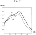
- FIG. 7 is a graph illustrating an example of a measured luminance profile, an intermediate target luminance profile and a final target luminance profile at gray level lower than a maximum gray level.
- FIG. 8 is a block diagram illustrating an exemplary embodiment of a display device.
- FIG. 9 is a diagram for describing an example of a bilinear interpolation performed by a data corrector included in a display device of FIG. 8 .
- FIG. 10 is a block diagram illustrating an exemplary embodiment of an electronic device including a display device.
- first,” “second,” “third” etc. may be used herein to describe various elements, components, regions, layers and/or sections, these elements, components, regions, layers and/or sections should not be limited by these terms. These terms are only used to distinguish one element, component, region, layer or section from another element, component, region, layer or section. Thus, “a first element,” “component,” “region,” “layer” or “section” discussed below could be termed a second element, component, region, layer or section without departing from the teachings herein.
- relative terms such as “lower” or “bottom” and “upper” or “top,” may be used herein to describe one element's relationship to another element as illustrated in the Figures. It will be understood that relative terms are intended to encompass different orientations of the device in addition to the orientation depicted in the Figures. For example, if the device in one of the figures is turned over, elements described as being on the “lower” side of other elements would then be oriented on “upper” sides of the other elements. The exemplary term “lower,” can therefore, encompasses both an orientation of “lower” and “upper,” depending on the particular orientation of the figure.
- spatially relative terms such as “beneath,” “below,” “lower,” “above,” “upper” and the like, may be used herein for ease of description to describe one element or feature's relationship to another element(s) or feature(s) as illustrated in the figures. It will be understood that the spatially relative terms are intended to encompass different orientations of the device in use or operation in addition to the orientation depicted in the figures. For example, if the device in the figures is turned over, elements described as “below” or “beneath” other elements or features would then be oriented “above” the other elements or features. Thus, the exemplary term “below” can encompass both an orientation of above and below. The device may be otherwise oriented (rotated 90 degrees or at other orientations) and the spatially relative descriptors used herein interpreted accordingly.
- “About” or “approximately” as used herein is inclusive of the stated value and means within an acceptable range of deviation for the particular value as determined by one of ordinary skill in the art, considering the measurement in question and the error associated with measurement of the particular quantity (i.e., the limitations of the measurement system). For example, “about” can mean within at least one standard deviations, or within ⁇ 30%, 20%, 10%, 5% of the stated value.
- Exemplary embodiments are described herein with reference to cross section illustrations that are schematic illustrations of idealized embodiments. As such, variations from the shapes of the illustrations as a result, for example, of manufacturing techniques and/or tolerances, are to be expected. Thus, embodiments described herein should not be construed as limited to the particular shapes of regions as illustrated herein but are to include deviations in shapes that result, for example, from manufacturing. For example, a region illustrated or described as flat may, typically, have rough and/or nonlinear features. Moreover, sharp angles that are illustrated may be rounded. Thus, the regions illustrated in the figures are schematic in nature and their shapes are not intended to illustrate the precise shape of a region and are not intended to limit the scope of the present claims.
- FIG. 1 is a flowchart illustrating a method of generating correction data for a display device according to exemplary embodiments
- FIG. 2 is a block diagram illustrating an example of a test equipment performing a method of FIG. 1
- FIG. 3A is a graph illustrating an example of a measured x-color coordinate profile and a target x-color coordinate profile at a maximum gray level
- FIG. 3B is a graph illustrating an example of a measured y-color coordinate profile and a target y-color coordinate profile at a maximum gray level
- FIG. 4 is a graph illustrating an example of a measured luminance profile, a maximum target luminance profile, an intermediate target luminance profile and a final target luminance profile at a maximum gray level
- FIG. 3A is a graph illustrating an example of a measured x-color coordinate profile and a target x-color coordinate profile at a maximum gray level
- FIG. 3B is a graph illustrating an example of a measured y-color coordinate profile and a target
- FIG. 5A is a graph illustrating an example of correction data for red sub-pixels a maximum gray level
- FIG. 5B is a graph illustrating an example of correction data for green sub-pixels a maximum gray level
- FIG. 5C is a graph illustrating an example of correction data for blue sub-pixels a maximum gray level
- FIG. 6 is a diagram for describing an example of a plurality of reference gray levels at which correction data are generated and stored.
- a method of generating correction data for a display device 200 may be performed by a test equipment 250 that performs an automatic test process (e.g., an automatic manual test (“AMT”) process).
- the test equipment 250 may obtain measured tristimulus data (e.g., international commission on illumination (“CIE”) 1931 XYZ data) of the display device 200 at a maximum gray level (e.g., a 255-gray level) by capturing a white image displayed at the maximum gray level by the display device 200 by a camera (e.g., a charge coupled device (“CCD”) camera) 270 (S 110 ).
- CIE international commission on illumination
- S 110 a charge coupled device
- the test equipment 250 may provide the display device 200 with white maximum gray data, for example RGB data including red data representing the maximum gray level, green data representing the maximum gray level and blue data representing the maximum gray level, and may obtain the measured tristimulus data at the maximum gray level by capturing the white image displayed by the display device 200 based on the white maximum gray data.
- white maximum gray data for example RGB data including red data representing the maximum gray level, green data representing the maximum gray level and blue data representing the maximum gray level
- a measured luminance profile and a measured color coordinate profile of the display device 200 at the maximum gray level may be obtained based on the measured tristimulus data at the maximum gray level (S 120 ).
- the measured tristimulus data (e.g., XYZ data) at the maximum gray level may be converted to luminance and color coordinate data (e.g., Lxy data) in a luminance and color coordinate domain (e.g., an Lxy domain).
- the measured luminance profile may be obtained based on luminance data (e.g., L data) among the luminance and color coordinate data, and the measured color coordinate profile may be obtained based on color coordinate data (e.g., xy data) among the luminance and color coordinate data.
- the measured color coordinate profile may include a measured x-color coordinate profile and a measured y-color coordinate profile.
- the measured x-color coordinate profile may be obtained based on x-color coordinate data (e.g., x data) among the luminance and color coordinate data
- the measured y-color coordinate profile may be obtained based on y-color coordinate data (e.g., y data) among the luminance and color coordinate data.
- a target color coordinate profile of the display device 200 at the maximum gray level may be determined based on the measured color coordinate profile (S 130 ).
- the target color coordinate profile may include a target x-color coordinate profile and a target y-color coordinate profile.
- the target x-color coordinate profile 330 may be determined by calculating a moving average for the measured x-color coordinate profile 310 .
- the target y-color coordinate profile 370 may be determined by calculating a moving average for the measured y-color coordinate profile 350 .
- the target x-color coordinate profile 330 and the target y-color coordinate profile 370 may be determined as smooth lines (or surfaces), and thus a color mura defect of the display device 200 may be removed or corrected by correction data generated based on the target color coordinate profile.
- FIGS. 3A and 3B illustrate x-color coordinate profiles 310 and 330 and y-color coordinate profiles 350 and 370 having line shapes corresponding to one horizontal pixel line for illustration purposes, the x-color coordinate profiles 310 and 330 and y-color coordinate profiles 350 and 370 according to exemplary embodiments may have surface shapes corresponding to the entire display panel.
- a measured red maximum luminance, a measured green maximum luminance and a measured blue maximum luminance of each pixel in the display device 200 may be obtained (S 140 ).
- the measured red maximum luminance of a pixel may represent a measured luminance of the pixel when data signals at a minimum gray level (e.g., a 0-gray level) are applied to green and blue sub-pixels of the pixel and a data signal at the maximum gray level (e.g., the 255-gray level) is applied to a red sub-pixel of the pixel.
- the measured green maximum luminance of a pixel may represent a measured luminance of the pixel when data signals at the minimum gray level are applied to the red and blue sub-pixels of the pixel and a data signal at the maximum gray level is applied to the green sub-pixel of the pixel.
- the measured blue maximum luminance of a pixel may represent a measured luminance of the pixel when data signals at the minimum gray level are applied to the red and green sub-pixels of the pixel and a data signal at the maximum gray level is applied to the blue sub-pixel of the pixel.
- the test equipment 250 may provide the display device 200 with red maximum gray data (e.g., RGB data including red data representing the maximum gray level and green and blue data representing the minimum gray level), may obtain the measured tristimulus data at a red maximum gray level (e.g., the 255-gray level for the red sub-pixel, and the 0-gray level for the green and blue sub-pixels) by capturing a red image displayed by the display device 200 based on the red maximum gray data, and may obtain the measured red maximum luminance of the each pixel from the measured tristimulus data at the red maximum gray level.
- red maximum gray data e.g., RGB data including red data representing the maximum gray level and green and blue data representing the minimum gray level
- the measured tristimulus data at a red maximum gray level e.g., the 255-gray level for the red sub-pixel, and the 0-gray level for the green and blue sub-pixels
- Y data for the each pixel among the measured tristimulus data (e.g., XYZ data) at the red maximum gray level may be obtained as the measured red maximum luminance, for example.
- the test equipment 250 may provide the display device 200 with green maximum gray data (e.g., RGB data including green data representing the maximum gray level and red and blue data representing the minimum gray level), may obtain the measured tristimulus data at a green maximum gray level (e.g., the 255-gray level for the green sub-pixel, and the 0-gray level for the red and blue sub-pixels) by capturing a green image displayed by the display device 200 based on the green maximum gray data, and may obtain the measured green maximum luminance of the each pixel from the measured tristimulus data at the green maximum gray level.
- green maximum gray data e.g., RGB data including green data representing the maximum gray level and red and blue data representing the minimum gray level
- the measured tristimulus data at a green maximum gray level e.g.,
- Y data for the each pixel among the measured tristimulus data (e.g., XYZ data) at the green maximum gray level may be obtained as the measured green maximum luminance, for example.
- the test equipment 250 may provide the display device 200 with blue maximum gray data (e.g., RGB data including blue data representing the maximum gray level and red and green data representing the minimum gray level), may obtain the measured tristimulus data at a blue maximum gray level (e.g., the 255-gray level for the blue sub-pixel, and the 0-gray level for the red and green sub-pixels) by capturing a blue image displayed by the display device 200 based on the blue maximum gray data, and may obtain the measured blue maximum luminance of the each pixel from the measured tristimulus data at the blue maximum gray level.
- Y data for the each pixel among the measured tristimulus data (e.g., XYZ data) at the blue maximum gray level may be obtained as the measured blue maximum luminance
- a maximum target luminance of the each pixel may be determined such that a red luminance, a green luminance and a blue luminance of the each pixel converted from the maximum target luminance and a target color coordinate of the each pixel at the maximum gray level become lower than or equal to the measured red maximum luminance, the measured green maximum luminance and the measured blue maximum luminance of the each pixel, respectively (S 150 ).
- target luminance and color coordinate data of the each pixel may be obtained by setting the maximum target luminance of the each pixel to a variable ⁇ and by obtaining the target color coordinate of the each pixel from the target color coordinate profile.
- the target luminance and color coordinate data of the each pixel may be
- the target luminance and color coordinate data of the each pixel may be converted to target tristimulus data of the each pixel.
- [ ⁇ Wx 255 ′ Wy 255 ′ ] may be converted to the target tristimulus data of the each pixel, or
- the target tristimulus data of the each pixel may be converted to the red luminance, the green luminance and the blue luminance of the each pixel by an XYZ-to-YrYgYb conversion matrix.
- the XYZ-to-YrYgYb conversion matrix may be:
- W xR represents an x-color coordinate value of a red image of the each pixel
- W yR represents a y-color coordinate value of the red image of the each pixel
- W zR is calculated by subtracting the x-color coordinate value and the y-color coordinate value of the red image of the each pixel from 1
- W xG represents an x-color coordinate value of a green image of the each pixel
- W yG represents a y-color coordinate value of the green image of the each pixel
- W zG is calculated by subtracting the x-color coordinate value and the y-color coordinate value of the green image of the each pixel from 1
- W xB represents an x-color coordinate value of a blue image of the each pixel
- W yB represents a y--
- variable a that allows the red luminance, the green luminance and the blue luminance of the each pixel to become lower than or equal to the measured red maximum luminance, the measured green maximum luminance and the measured blue maximum luminance of the each pixel, respectively, may be determined as the maximum target luminance of the each pixel.
- the maximum target luminance of the each pixel may be determined using an equation:
- a final target luminance profile of the display device 200 at the maximum gray level may be determined based on the measured luminance profile and the maximum target luminance of the each pixel (S 160 ).
- the measured luminance profile 410 at the maximum gray level may be obtained based on the measured tristimulus data at the maximum gray level
- a maximum target luminance profile 430 representing the maximum target luminances of respective pixels may be obtained by calculating the maximum target luminances for the respective pixels
- an intermediate target luminance profile 450 may be determined by calculating a moving average for the measured luminance profile 410 at the maximum gray level
- the final target luminance profile 470 at the maximum gray level may be determined by adjusting the intermediate target luminance profile 450 to become lower than or equal to the maximum target luminance of the each pixel (or to become lower than or equal to the maximum target luminance profile 430 at any position or at any pixel).
- the final target luminance profile 470 may be set as close as possible to the maximum target luminance profile 430 , and thus a luminance loss of the display device 200 may be minimized.
- the final target luminance profile 470 may be determined by shifting the intermediate target luminance profile 450 by the maximum difference between the maximum target luminance profile 430 and the intermediate target luminance profile 450 .
- a smooth curve corresponding to a difference between the maximum target luminance profile 430 and the intermediate target luminance profile 450 may be obtained by performing spatial filtering at positions where the maximum target luminance profile 430 is higher than the intermediate target luminance profile 450 , and the final target luminance profile 470 lower than, but close to, the maximum target luminance profile 430 may be obtained by subtracting the obtained smooth curve from the intermediate target luminance profile 450 .
- the final target luminance profile 470 at the maximum gray level may be determined as a smooth line (or surface) close to the maximum target luminance profile 430 .
- FIG. 4 illustrates luminance profiles 410 , 430 , 450 and 470 having line shapes corresponding to one horizontal pixel line for illustration purposes
- the luminance profiles 410 , 430 , 450 and 470 in exemplary embodiments may have surface shapes corresponding to the entire display panel.
- the correction data at the maximum gray level may be generated based on the final target luminance profile and the target color coordinate profile at the maximum gray level, and the correction data at the maximum gray level may be stored in the display device 200 (S 170 ).
- a target red luminance, a target blue luminance and a target green luminance of the each pixel may be calculated based on the final target luminance profile and the target color coordinate profile at the maximum gray level, a target red gray level, a target green gray level and a target blue gray level respectively corresponding to the target red luminance, the target blue luminance and the target green luminance of the each pixel may be obtained, and a value generated by subtracting a maximum red gray level from the target red gray level, a value generated by subtracting a maximum green gray level from the target green gray level and a value generated by subtracting a maximum blue gray level from the target blue gray level may be stored as the correction data at the maximum gray level in the display device 200 .
- a target luminance of a pixel may be obtained from the final target luminance profile
- a target color coordinate of the pixel may be obtained from the target color coordinate profile
- a target tristimulus value of the pixel may be obtained by converting the target luminance and the target color coordinate of the pixel to the target tristimulus value in a tristimulus domain (or an XYZ domain)
- the target red luminance, the target blue luminance and the target green luminance of the pixel may be calculated by an equation, for example:
- Y R ⁇ _ ⁇ target Y G ⁇ _ ⁇ target Y B ⁇ _ ⁇ target may be the target red luminance, the target blue luminance and the target green luminance of the pixel.
- the target red gray level of the pixel may be obtained from the target red luminance of the pixel and a gray-luminance profile for a red sub-pixel of the pixel
- the target green gray level of the pixel may be obtained from the target green luminance of the pixel and a gray-luminance profile for a green sub-pixel of the pixel
- the target blue gray level of the pixel may be obtained from the target blue luminance of the pixel and a gray-luminance profile for a blue sub-pixel of the pixel.
- the gray-luminance profiles for the red, green and blue sub-pixels may be obtained by luminances measured at predetermined reference gray levels.
- the correction data for the pixel at the maximum gray level may include a correction value for the red sub-pixel of the pixel, a correction value for the green sub-pixel of the pixel and a correction value for the blue sub-pixel of the pixel
- the correction value for the red sub-pixel may be a value generated by subtracting the maximum red gray level (e.g., the 255-gray level) from the target red gray level
- the correction value for the green sub-pixel may be a value generated by subtracting the maximum green gray level (e.g., the 255-gray level) from the target green gray level
- the correction value for the blue sub-pixel may be a value generated by subtracting the maximum blue gray level (e.g., the 255-gray level) from the target blue gray level.
- the correction data at the maximum gray level may have the correction values lower than or equal to 0.
- a reference numeral 520 may represent an example of correction values for red sub-pixels included in respective pixels
- a reference numeral 540 may represent an example of correction values for green sub-pixels included in the respective pixels
- a reference numeral 560 may represent an example of correction values for blue sub-pixels included in the respective pixels. Since the correction data 520 , 540 and 560 at the maximum gray level have only the negative correction values or the correction values of 0, the display device 200 may remove or correct the luminance mura defect and/or the color mura defect even at the maximum gray level.
- the correction data may be generated and stored not only at the maximum gray level but also at at least one gray level lower than the maximum gray level.
- the correction data may be obtained at the entire gray levels (e.g., 256 gray levels from the 0-gray level to the 255-gray level. However, in this case, a size of the correction data may be excessively increased.
- the correction data may be obtained at at least one reference gray level corresponding to a portion of the entire gray levels. In an exemplary embodiment, as illustrated in FIG.
- the correction data may be obtained at ten reference gray levels, or 0-gray level 0G, 16-gray level 16G, 24-gray level 24G, 32-gray level 32G, 64-gray level 64G, 128-gray level 128G, 160-gray level 160G, 192-gray level 192G, 224-gray level 224G and 255-gray level 255G, for example.
- the at least one reference gray level in exemplary embodiments may not be limited to the ten reference gray levels as illustrated in FIG. 6 .
- the final target luminance profile at the at least one reference gray level lower than the maximum gray level may be obtained by applying a reduction ratio of an average of the final target luminance profile at the maximum gray level to an average of the measured luminance profile at the maximum gray level (or an average of the intermediate target luminance profile at the maximum gray level) to an intermediate target luminance profile at the at least one reference gray level (S 180 ), the correction data at the at least one reference gray level may be generated based on the final target luminance profile at at least one reference gray level, and the correction data at the at least one reference gray level may be stored in the display device 200 (S 190 ).
- the measured tristimulus data at the at least one reference gray level may be obtained by capturing an image at the at least one reference gray level lower than the maximum gray level displayed by the display device 200 , the measured luminance profile and the measured color coordinate profile at the at least one reference gray level may be obtained based on the measured tristimulus data at the at least one reference gray level, the intermediate target luminance profile at the at least one reference gray level may be determined by calculating a moving average for the measured luminance profile at the at least one reference gray level, and the target color coordinate profile at the at least one reference gray level may be determined by calculating a moving average for the measured color coordinate profile at the at least one reference gray level, for example.
- the measured tristimulus data at the at least one reference gray level may be obtained by capturing an image at the at least one reference gray level lower than the maximum gray level displayed by the display device 200 , the measured luminance profile and the measured color coordinate profile at the at least one reference gray level may be obtained based on the measured tristimulus data at the at least
- the intermediate target luminance profile 740 at the reference gray level may be obtained by calculating the moving average for the measured luminance profile 720 at the reference gray level, for example. Further, the final target luminance profile 760 at the reference gray level may be obtained by multiplying the intermediate target luminance profile 740 by the reduction ratio of the average of the final target luminance profile at the maximum gray level to the average of the measured luminance profile at the maximum gray level (or the average of the intermediate target luminance profile at the maximum gray level).
- the correction data at the reference gray level may be determined based on the final target luminance profile 760 and the target color coordinate profile at the reference gray level. As described above, since the reduction ratio at the maximum gray level is also applied to the reference gray level lower than the maximum gray level, a gamma characteristic of the display device 200 may not be changed.
- the maximum target luminance of each pixel may be determined such that the red luminance, the green luminance and the blue luminance of the each pixel converted from the maximum target luminance and the target color coordinate of the each pixel at the maximum gray level (e.g., the 255-gray level) may become lower than or equal to the measured red maximum luminance, the measured green maximum luminance and the measured blue maximum luminance, respectively, and the final target luminance profile at the maximum gray level may be determined based on the measured luminance profile and the maximum target luminance of the each pixel. Accordingly, the correction data may be generated even at the maximum gray level, and the display device 200 may perform luminance mura correction and/or color mura correction even at the maximum gray level based on the correction data.
- the maximum gray level e.g., the 255-gray level
- FIG. 8 is a block diagram illustrating an exemplary embodiment of a display device
- FIG. 9 is a diagram for describing an example of a bilinear interpolation performed by a data corrector included in a display device of FIG. 8 .
- a display device 800 in exemplary embodiments may include a display panel 810 that includes a plurality of pixels PX, a correction data memory 820 that stores correction data CD, a data corrector 830 that corrects image data IDAT based on the correction data CD, a data driver 850 that provides data signals DS to the plurality of pixels PX, a gate driver 860 that provides gate signals GS to the plurality of pixels PX, and a controller 840 that controls an operation of the display device 800 .
- the display panel 810 may include a plurality of data lines, a plurality of gate lines, and the plurality of pixels PX coupled to the plurality of data lines and the plurality of gate lines.
- each pixel PX may include a switching transistor and a liquid crystal capacitor coupled to the switching transistor, and the display panel 810 may be a liquid crystal display (“LCD”) panel.
- each pixel PX may include an organic light emitting diode (“OLED”), at least one capacitor and at least two transistors, and the display panel 810 may be an OLED display panel.
- OLED organic light emitting diode
- the display panel 810 may not be limited to the LCD panel and the OLED display panel, and may be any suitable display panel.
- the correction data memory 820 may store the correction data CD at a plurality reference gray levels (e.g., 10 gray levels in FIG. 6 ) including a maximum gray level (e.g., a 255-gray level).
- measured tristimulus data at the maximum gray level may be obtained by capturing a white image at the maximum gray level displayed by the display device 800 , a measured luminance profile and a measured color coordinate profile at the maximum gray level may be obtained based on the measured tristimulus data at the maximum gray level, a target color coordinate profile at the maximum gray level may be determined based on the measured color coordinate profile, a measured red maximum luminance, a measured green maximum luminance and a measured blue maximum luminance of each pixel PX may be obtained, a maximum target luminance of the each pixel PX may be determined such that a red luminance, a green luminance and a blue luminance of the each pixel PX converted from the maximum target luminance and a target color coordinate of the each pixel PX at
- target luminance and color coordinate data of the each pixel PX may be obtained by setting the maximum target luminance of the each pixel PX to a variable a and by obtaining the target color coordinate of the each pixel PX from the target color coordinate profile, the target luminance and color coordinate data of the each pixel PX may be converted to target tristimulus data of the each pixel PX, the target tristimulus data of the each pixel PX may be converted to the red luminance, the green luminance and the blue luminance of the each pixel PX by an XYZ-to-YrYgYb conversion matrix, and the variable a may be determined as the maximum target luminance of the each pixel PX such that the red luminance, the green luminance and the blue luminance of the each pixel PX become lower than or equal to the measured red maximum luminance, the measured green maximum luminance and the measured blue maximum luminance of the each pixel PX, respectively.
- the maximum target luminance of the each pixel PX may be determined using an equation:
- the data corrector 830 may correct the image data IDAT based on the correction data CD, and may output the corrected image data CIDAT.
- the correction data CD may include a plurality of correction values only at a plurality of sampling positions corresponding to a portion of the entire pixels PX of the display panel 810 .
- the data corrector 830 may correct the image data IDAT for the each pixel PX by performing a bilinear interpolation on the plurality of correction values at four sampling points adjacent to the each pixel PX among the plurality of sampling positions.
- the data corrector 830 may perform the bilinear interpolation on correction values at first through fourth sampling positions SP 1 , SP 2 , SP 3 and SP 4 adjacent to the pixel PX, for example. That is, the data corrector 830 may calculate a correction value at a first intermediate position PA by performing a linear interpolation on the correction values at the first and second sampling positions SP 1 and SP 2 , may calculate a correction value at a second intermediate position PB by performing a linear interpolation on the correction values at the third and fourth sampling positions SP 3 and SP 4 , and may calculate a correction value for the pixel PX by performing a linear interpolation on the correction values at the first and second intermediate positions PA and PB.
- the correction data CD may be stored at each of a plurality of reference gray levels, and the data corrector 830 may correct, with respect to each pixel PX, the image data IDAT for the each pixel PX by performing a linear interpolation on the plurality of correction values at two reference gray levels adjacent to a gray level of the image data IDAT for the each pixel PX among the plurality of reference gray levels.
- the linear interpolation between gray levels may be performed after the bilinear interpolation is performed, or may be performed before the bilinear interpolation is performed.
- the correction data CD stored in the correction data memory 820 may include the correction data CD at the maximum gray level (e.g., the 255-gray level), and the correction data CD at the maximum gray level may have correction values lower than or equal to 0.
- the data corrector 830 may correct the data IDAT representing the maximum gray level based on the correction data CD at the maximum gray level which have the correction values lower than or equal to 0. Accordingly, the display device 800 may remove or correct the luminance mura defect and/or the color mura defect even at the maximum gray level.
- the controller 840 may receive a control signal CTRL from an external host processor (e.g., a graphic processing unit (“GPU”) or a graphic card), and may receive the corrected image data CIDAT from the data corrector 830 .
- the control signal CTRL may include, but not be limited to, a vertical synchronization signal, a horizontal synchronization signal, an input data enable signal, a master clock signal, etc.
- the controller 840 may generate a gate control signal GCTRL and a data control signal DCTRL based on the control signal CTRL. Further, the controller 840 may generate dithered image data DIDAT by performing a dithering operation based on the corrected image data CIDAT.
- the controller 840 may perform a spatial dithering operation.
- the controller 840 may output the dithered image data DIDAT having a value of 10 with respect to three pixels PX of the adjacent four pixels PX, and may output the dithered image data DIDAT having a value of 11 with respect to one pixel PX of the adjacent four pixels PX, for example.
- the controller 840 may perform a temporal dithering operation.
- the controller 840 may output the dithered image data DIDAT having a value of 10 with respect to the pixel PX in three frames of the consecutive four frames, and may output the dithered image data DIDAT having a value of ‘11’ with respect to the pixel PX in the remaining one frame of the consecutive four frames, for example.
- the controller 840 may perform both of the spatial dithering operation and the temporal dithering operation.
- the data driver 850 may generate the data signals DS based on the dithered image data DIDAT and the data control signal DCTRL output from the controller 840 , and may provide the data signals DS corresponding to the dithered image data DIDAT to the plurality of pixels PX.
- the data control signal DCTRL may include, but not be limited to, an output data enable signal, a horizontal start signal and a load signal, for example.
- the data driver 850 may be implemented with at least one data integrated circuit (“IC”).
- the data driver 850 may be disposed (e.g., mounted) directly on the display panel 810 , or may be coupled to the display panel 810 in a form of a tape carrier package (“TCP”). In other exemplary embodiments, the data driver 850 may be integrated in a peripheral portion of the display panel 810 .
- TCP tape carrier package
- the gate driver 860 may generate the gate signals GS based on the gate control signal GCTRL from the controller 840 , and may provide the gate signals GS to the plurality of pixels PX.
- the gate control signal GCTRL may include, but not be limited to, a frame start signal and a gate clock signal.
- the gate driver 860 may be implemented as an amorphous silicon gate (“ASG”) driver integrated in the peripheral portion of the display panel 810 .
- the gate driver 860 may be implemented with at least one gate IC.
- the gate driver 860 may be disposed (e.g., mounted) directly on the display panel 810 , or may be coupled to the display panel 810 in the form of the TCP.
- the display device 800 in exemplary embodiments may store the correction data CD at the plurality of reference gray levels including the maximum gray level (e.g., the 255-gray level), and the correction data CD at the maximum gray level may have the correction values less than or equal to 0. Accordingly, the display device 800 in exemplary embodiments may perform the luminance mura correction and/or the color mura correction even at the maximum gray level based on the correction data CD.
- the maximum gray level e.g., the 255-gray level
- the correction data CD at the maximum gray level may have the correction values less than or equal to 0. Accordingly, the display device 800 in exemplary embodiments may perform the luminance mura correction and/or the color mura correction even at the maximum gray level based on the correction data CD.
- FIG. 10 is a block diagram illustrating an electronic device including a display device in exemplary embodiments.
- an electronic device 1100 may include a processor 1110 , a memory device 1120 , a storage device 1130 , an input/output (“I/O”) device 1140 , a power supply 1150 , and a display device 1160 .
- the electronic device 1100 may further include a plurality of ports for communicating a video card, a sound card, a memory card, a universal serial bus (“USB”) device, other electric devices, etc.
- USB universal serial bus
- the processor 1110 may perform various computing functions or tasks.
- the processor 1110 may be an application processor (“AP”), a micro processor, a central processing unit (“CPU”), etc.
- the processor 1110 may be coupled to other components via an address bus, a control bus, a data bus, etc. Further, in some exemplary embodiments, the processor 1110 may be further coupled to an extended bus such as a peripheral component interconnection (“PCI”) bus.
- PCI peripheral component interconnection
- the memory device 1120 may store data for operations of the electronic device 1100 .
- the memory device 1120 may include at least one non-volatile memory device such as an erasable programmable read-only memory (“EPROM”) device, an electrically erasable programmable read-only memory (“EEPROM”) device, a flash memory device, a phase change random access memory (“PRAM”) device, a resistance random access memory (“RRAM”) device, a nano floating gate memory (“NFGM”) device, a polymer random access memory (“PoRAM”) device, a magnetic random access memory (“MRAM”) device, a ferroelectric random access memory (“FRAM”) device, etc., and/or at least one volatile memory device such as a dynamic random access memory (“DRAM”) device, a static random access memory (“SRAM”) device, a mobile dynamic random access memory (“mobile DRAM”) device, etc., for example.
- DRAM dynamic random access memory
- SRAM static random access memory
- mobile DRAM mobile dynamic random access memory
- the storage device 1130 may be a solid state drive (“SSD”) device, a hard disk drive (“HDD”) device, a CD-ROM device, etc.
- the I/O device 1140 may be an input device such as a keyboard, a keypad, a mouse, a touch screen, etc., and an output device such as a printer, a speaker, etc.
- the power supply 1150 may supply power for operations of the electronic device 1100 .
- the display device 1160 may be coupled to other components through the buses or other communication links.
- the display device 1160 may store correction data at a plurality of reference gray levels including a maximum gray level, and the correction data at the maximum gray level may have correction values less than or equal to 0. Accordingly, the display device 1160 may perform luminance mura correction and/or color mura correction even at the maximum gray level based on the correction data.
- the inventions may be applied to any display device 1160 performing the mura correction, and any electronic device 1100 including the display device 1160 .
- the inventions may be applied to a television (“TV”), a digital TV, a three dimensional (“3D”) TV, a smart phone, a wearable electronic device, a tablet computer, a mobile phone, a personal computer (“PC”), a home appliance, a laptop computer, a personal digital assistant (“PDA”), a portable multimedia player (“PMP”), a digital camera, a music player, a portable game console, a navigation device, etc., for example.
- TV television
- digital TV digital TV
- 3D three dimensional
- smart phone a wearable electronic device
- tablet computer a mobile phone
- PC personal computer
- PDA personal digital assistant
- PMP portable multimedia player
- digital camera a music player
- a portable game console a navigation device, etc.
Abstract
Description
where WxR represents an x-color coordinate value of a red image of the each pixel, WyR represents a y-color coordinate value of the red image of the each pixel, WzR is calculated by subtracting the x-color coordinate value and the y-color coordinate value of the red image of the each pixel from 1, WxG represents an x-color coordinate value of a green image of the each pixel, WyG represents a y-color coordinate value of the green image of the each pixel, WzG is calculated by subtracting the x-color coordinate value and the y-color coordinate value of the green image of the each pixel from 1, WxB represents an x-color coordinate value of a blue image of the each pixel, WyB represents a y-color coordinate value of the blue image of the each pixel, and WzB is calculated by subtracting the x-color coordinate value and the y-color coordinate value of the blue image of the each pixel from 1.
where α represents the maximum target luminance of the each pixel, Wx′255 represents an x-color coordinate value of the target color coordinate of the each pixel, Wy′255 represents a y-color coordinate value of the target color coordinate of the each pixel, Wz′255 is calculated by subtracting the x-color coordinate value and the y-color coordinate value of the target color coordinate of the each pixel from 1, YR255 represents the measured red maximum luminance, YG255 represents the measured green maximum luminance, YB255 represents the measured blue maximum luminance, WxR represents an x-color coordinate value of a red image of the each pixel, WyR represents a y-color coordinate value of the red image of the each pixel, WzR is calculated by subtracting the x-color coordinate value and the y-color coordinate value of the red image of the each pixel from 1, WxG represents an x-color coordinate value of a green image of the each pixel, WyG represents a y-color coordinate value of the green image of the each pixel, WzG is calculated by subtracting the x-color coordinate value and the y-color coordinate value of the green image of the each pixel from 1, WxB represents an x-color coordinate value of a blue image of the each pixel, WyB represents a y-color coordinate value of the blue image of the each pixel, and WzB is calculated by subtracting the x-color coordinate value and the y-color coordinate value of the blue image of the each pixel from 1.
where WxR represents an x-color coordinate value of a red image of the each pixel, WyR represents a y-color coordinate value of the red image of the each pixel, WzR is calculated by subtracting the x-color coordinate value and the y-color coordinate value of the red image of the each pixel from 1, WxG represents an x-color coordinate value of a green image of the each pixel, WyG represents a y-color coordinate value of the green image of the each pixel, WzG is calculated by subtracting the x-color coordinate value and the y-color coordinate value of the green image of the each pixel from 1, WxB represents an x-color coordinate value of a blue image of the each pixel, WyB represents a y-color coordinate value of the blue image of the each pixel, and WzB is calculated by subtracting the x-color coordinate value and the y-color coordinate value of the blue image of the each pixel from 1.
-
- where α represents the maximum target luminance of the each pixel, Wx′255 represents an x-color coordinate value of the target color coordinate of the each pixel, Wy′255 represents a y-color coordinate value of the target color coordinate of the each pixel, Wz′255 is calculated by subtracting the x-color coordinate value and the y-color coordinate value of the target color coordinate of the each pixel from 1, YR255 represents the measured red maximum luminance, YG255 represents the measured green maximum luminance, YB255 represents the measured blue maximum luminance, WxR represents an x-color coordinate value of a red image of the each pixel, WyR represents a y-color coordinate value of the red image of the each pixel, WzR is calculated by subtracting the x-color coordinate value and the y-color coordinate value of the red image of the each pixel from 1, WxG represents an x-color coordinate value of a green image of the each pixel, WyG represents a y-color coordinate value of the green image of the each pixel, WzG is calculated by subtracting the x-color coordinate value and the y-color coordinate value of the green image of the each pixel from 1, WxB represents an x-color coordinate value of a blue image of the each pixel, WyB represents a y-color coordinate value of the blue image of the each pixel, and WzB is calculated by subtracting the x-color coordinate value and the y-color coordinate value of the blue image of the each pixel from 1.
where Wx′255 represents an x-color coordinate value of the target color coordinate of the each pixel, and Wy′255 represents a y-color coordinate value of the target color coordinate of the each pixel, for example. The target luminance and color coordinate data of the each pixel may be converted to target tristimulus data of the each pixel. In an exemplary embodiment, the target luminance and color coordinate data of the each pixel, or
may be converted to the target tristimulus data of the each pixel, or
for example. The target tristimulus data of the each pixel may be converted to the red luminance, the green luminance and the blue luminance of the each pixel by an XYZ-to-YrYgYb conversion matrix. In some exemplary embodiments, the XYZ-to-YrYgYb conversion matrix may be:
where WxR represents an x-color coordinate value of a red image of the each pixel, WyR represents a y-color coordinate value of the red image of the each pixel, WzR is calculated by subtracting the x-color coordinate value and the y-color coordinate value of the red image of the each pixel from 1, WxG represents an x-color coordinate value of a green image of the each pixel, WyG represents a y-color coordinate value of the green image of the each pixel, WzG is calculated by subtracting the x-color coordinate value and the y-color coordinate value of the green image of the each pixel from 1, WxB represents an x-color coordinate value of a blue image of the each pixel, WyB represents a y-color coordinate value of the blue image of the each pixel, and WzB is calculated by subtracting the x-color coordinate value and the y-color coordinate value of the blue image of the each pixel from 1. The variable a that allows the red luminance, the green luminance and the blue luminance of the each pixel to become lower than or equal to the measured red maximum luminance, the measured green maximum luminance and the measured blue maximum luminance of the each pixel, respectively, may be determined as the maximum target luminance of the each pixel.
where α represents the maximum target luminance of the each pixel, Wx′255 represents an x-color coordinate value of the target color coordinate of the each pixel, Wy′255 represents a y-color coordinate value of the target color coordinate of the each pixel, Wz′255 is calculated by subtracting the x-color coordinate value and the y-color coordinate value of the target color coordinate of the each pixel from 1, YR255 represents the measured red maximum luminance, YG255 represents the measured green maximum luminance, YB255 represents the measured blue maximum luminance, WxR represents an x-color coordinate value of a red image of the each pixel, WyR represents a y-color coordinate value of the red image of the each pixel, WzR is calculated by subtracting the x-color coordinate value and the y-color coordinate value of the red image of the each pixel from 1, WxG represents an x-color coordinate value of a green image of the each pixel, WyG represents a y-color coordinate value of the green image of the each pixel, WzG is calculated by subtracting the x-color coordinate value and the y-color coordinate value of the green image of the each pixel from 1, WxB represents an x-color coordinate value of a blue image of the each pixel, WyB represents a y-color coordinate value of the blue image of the each pixel, and WzB is calculated by subtracting the x-color coordinate value and the y-color coordinate value of the blue image of the each pixel from 1.
may be the target tristimulus value of the pixel, and
may be the target red luminance, the target blue luminance and the target green luminance of the pixel. Further, the target red gray level of the pixel may be obtained from the target red luminance of the pixel and a gray-luminance profile for a red sub-pixel of the pixel, the target green gray level of the pixel may be obtained from the target green luminance of the pixel and a gray-luminance profile for a green sub-pixel of the pixel, and the target blue gray level of the pixel may be obtained from the target blue luminance of the pixel and a gray-luminance profile for a blue sub-pixel of the pixel. The gray-luminance profiles for the red, green and blue sub-pixels may be obtained by luminances measured at predetermined reference gray levels.
where α represents the maximum target luminance of the each pixel PX, Wx′255 represents an x-color coordinate value of the target color coordinate of the each pixel PX, Wy′255 represents a y-color coordinate value of the target color coordinate of the each pixel PX, YR255 represents the measured red maximum luminance, YG255 represents the measured green maximum luminance, YB255 represents the measured blue maximum luminance, WxR represents an x-color coordinate value of a red image of the each pixel PX, WyR represents a y-color coordinate value of the red image of the each pixel PX, WzR is calculated by subtracting the x-color coordinate value and the y-color coordinate value of the red image of the each pixel PX from 1, WxG represents an x-color coordinate value of a green image of the each pixel PX, WyG represents a y-color coordinate value of the green image of the each pixel PX, WzG is calculated by subtracting the x-color coordinate value and the y-color coordinate value of the green image of the each pixel PX from 1, WxB represents an x-color coordinate value of a blue image of the each pixel PX, WyB represents a y-color coordinate value of the blue image of the each pixel PX, and WzB is calculated by subtracting the x-color coordinate value and the y-color coordinate value of the blue image of the each pixel PX from 1.
where α represents the maximum target luminance of the each pixel PX, Wx′255 represents an x-color coordinate value of the target color coordinate of the each pixel PX, Wy′255 represents a y-color coordinate value of the target color coordinate of the each pixel PX, Wz′255 is calculated by subtracting the x-color coordinate value and the y-color coordinate value of the target color coordinate of the each pixel from 1, YR255 represents the measured red maximum luminance, YG255 represents the measured green maximum luminance, and YB255 represents the measured blue maximum luminance.
Claims (17)
Applications Claiming Priority (2)
| Application Number | Priority Date | Filing Date | Title |
|---|---|---|---|
| KR10-2019-0002442 | 2019-01-08 | ||
| KR1020190002442A KR102599506B1 (en) | 2019-01-08 | 2019-01-08 | Method of generating correction data for display devcie, and display device storing correction data |
Publications (2)
| Publication Number | Publication Date |
|---|---|
| US20200219433A1 US20200219433A1 (en) | 2020-07-09 |
| US11257417B2 true US11257417B2 (en) | 2022-02-22 |
Family
ID=71404486
Family Applications (1)
| Application Number | Title | Priority Date | Filing Date |
|---|---|---|---|
| US16/710,164 Active 2040-01-27 US11257417B2 (en) | 2019-01-08 | 2019-12-11 | Method of generating correction data for display device, and display device storing correction data |
Country Status (3)
| Country | Link |
|---|---|
| US (1) | US11257417B2 (en) |
| KR (1) | KR102599506B1 (en) |
| CN (1) | CN111415615A (en) |
Families Citing this family (6)
| Publication number | Priority date | Publication date | Assignee | Title |
|---|---|---|---|---|
| KR102640015B1 (en) * | 2019-12-31 | 2024-02-27 | 엘지디스플레이 주식회사 | Display device and driving method thereof |
| US10943530B1 (en) * | 2020-02-24 | 2021-03-09 | Himax Technologies Limited | Mura compensation method and apparatus for OLED display and electronic device |
| KR20210125642A (en) * | 2020-04-08 | 2021-10-19 | 삼성디스플레이 주식회사 | Display device performing peak luminance driving, and method of operating a display device |
| CN112365858B (en) * | 2020-12-10 | 2022-03-08 | 深圳市华星光电半导体显示技术有限公司 | Target color point capturing method in gamma correction and gamma correction system |
| CN113393803B (en) * | 2021-05-24 | 2022-08-19 | 卡莱特云科技股份有限公司 | Picture generation method and device in correction process |
| US20230066071A1 (en) * | 2021-09-02 | 2023-03-02 | Semiconductor Energy Laboratory Co., Ltd. | Image correction method and image correction system |
Citations (9)
| Publication number | Priority date | Publication date | Assignee | Title |
|---|---|---|---|---|
| US20090262114A1 (en) * | 2008-04-16 | 2009-10-22 | Samsung Electronics Co., Ltd. | Method and system of generating gamma data of display device |
| KR20140093011A (en) | 2013-01-17 | 2014-07-25 | 삼성디스플레이 주식회사 | Method of displaying an image, display apparatus performing the same, method and apparatus of calculating a correction value applied to the same |
| KR20150030013A (en) | 2013-09-11 | 2015-03-19 | 삼성디스플레이 주식회사 | Method of driving a display panel, display apparatus performing the same, method of calculating a correction value applied to the same and method of correcting gray data |
| US20150348505A1 (en) * | 2014-05-30 | 2015-12-03 | Samsung Display Co., Ltd. | Methods of correcting gamma and display device employing the same |
| US20160125787A1 (en) * | 2014-11-03 | 2016-05-05 | Lg Display Co., Ltd. | Timing Controller, Display Device, And Method Of Driving The Same |
| KR20170002770A (en) | 2015-06-29 | 2017-01-09 | 삼성디스플레이 주식회사 | Inspection apparatus of inspecting mura defects and method of driving the same |
| US9721530B2 (en) | 2014-07-21 | 2017-08-01 | Samsung Display Co., Ltd. | Method of displaying an image, display apparatus performing the same, method of calculating a correction value applied to the same and method of correcting grayscale data |
| KR20170106527A (en) | 2016-03-10 | 2017-09-21 | 삼성디스플레이 주식회사 | Inspection apparatus of inspecting mura defects, method of driving the inspection apparatus and display apparatus having correction value of mura defects |
| KR101784216B1 (en) | 2011-02-14 | 2017-10-12 | 삼성디스플레이 주식회사 | Compensation table generating system, display apparatus having brightness compensating table and method of generating compensation table |
Family Cites Families (4)
| Publication number | Priority date | Publication date | Assignee | Title |
|---|---|---|---|---|
| KR102536685B1 (en) * | 2016-02-26 | 2023-05-26 | 삼성디스플레이 주식회사 | Luminance correction system and method for correcting luminance of display panel |
| CN106782303B (en) * | 2016-12-28 | 2018-12-25 | 上海天马有机发光显示技术有限公司 | A kind of display bearing calibration of display panel, apparatus and system |
| CN107134260B (en) * | 2017-06-30 | 2019-05-10 | 京东方科技集团股份有限公司 | A kind of display control method, device and display device |
| CN107665684B (en) * | 2017-10-13 | 2020-01-14 | 深圳吉迪思电子科技有限公司 | Color Mura compensation method |
-
2019
- 2019-01-08 KR KR1020190002442A patent/KR102599506B1/en active IP Right Grant
- 2019-12-11 US US16/710,164 patent/US11257417B2/en active Active
-
2020
- 2020-01-08 CN CN202010016881.1A patent/CN111415615A/en active Pending
Patent Citations (10)
| Publication number | Priority date | Publication date | Assignee | Title |
|---|---|---|---|---|
| US20090262114A1 (en) * | 2008-04-16 | 2009-10-22 | Samsung Electronics Co., Ltd. | Method and system of generating gamma data of display device |
| KR101784216B1 (en) | 2011-02-14 | 2017-10-12 | 삼성디스플레이 주식회사 | Compensation table generating system, display apparatus having brightness compensating table and method of generating compensation table |
| KR20140093011A (en) | 2013-01-17 | 2014-07-25 | 삼성디스플레이 주식회사 | Method of displaying an image, display apparatus performing the same, method and apparatus of calculating a correction value applied to the same |
| KR20150030013A (en) | 2013-09-11 | 2015-03-19 | 삼성디스플레이 주식회사 | Method of driving a display panel, display apparatus performing the same, method of calculating a correction value applied to the same and method of correcting gray data |
| US20150348505A1 (en) * | 2014-05-30 | 2015-12-03 | Samsung Display Co., Ltd. | Methods of correcting gamma and display device employing the same |
| US9721530B2 (en) | 2014-07-21 | 2017-08-01 | Samsung Display Co., Ltd. | Method of displaying an image, display apparatus performing the same, method of calculating a correction value applied to the same and method of correcting grayscale data |
| US20160125787A1 (en) * | 2014-11-03 | 2016-05-05 | Lg Display Co., Ltd. | Timing Controller, Display Device, And Method Of Driving The Same |
| KR20170002770A (en) | 2015-06-29 | 2017-01-09 | 삼성디스플레이 주식회사 | Inspection apparatus of inspecting mura defects and method of driving the same |
| US9940883B2 (en) | 2015-06-29 | 2018-04-10 | Samsung Display Co., Ltd. | Display panel inspection apparatus |
| KR20170106527A (en) | 2016-03-10 | 2017-09-21 | 삼성디스플레이 주식회사 | Inspection apparatus of inspecting mura defects, method of driving the inspection apparatus and display apparatus having correction value of mura defects |
Also Published As
| Publication number | Publication date |
|---|---|
| KR20200086415A (en) | 2020-07-17 |
| CN111415615A (en) | 2020-07-14 |
| US20200219433A1 (en) | 2020-07-09 |
| KR102599506B1 (en) | 2023-11-08 |
Similar Documents
| Publication | Publication Date | Title |
|---|---|---|
| US11257417B2 (en) | Method of generating correction data for display device, and display device storing correction data | |
| CN110444152B (en) | Optical compensation method and device, display method and storage medium | |
| US20180330682A1 (en) | Mura phenomenon compensation method of display panel and display panel | |
| US10170063B2 (en) | Mura compensation method for display panel and display panel | |
| US9886909B2 (en) | Display device and method for driving display device | |
| WO2020024479A1 (en) | Bright spot compensation method and device for curved screen | |
| US20170032742A1 (en) | Luminance uniformity correction for display panels | |
| US9691337B2 (en) | Digital gamma correction part, display apparatus having the same and method of driving display panel using the same | |
| CN108122525B (en) | Display device and image processing method thereof | |
| CN111243512B (en) | Gray-scale data compensation method and device and driving chip | |
| CN108122546B (en) | Display apparatus and image processing method thereof | |
| US10553165B2 (en) | Method and apparatus for detecting high-frequency component in image | |
| US10878740B2 (en) | Method of generating correction data for display device, and display device storing correction data | |
| US20200226969A1 (en) | Display apparatus and display system | |
| US11257462B2 (en) | Display device, a method of generating compensation data for a display device, and a method of operating a display device | |
| US11488524B2 (en) | Organic light emitting diode display device, and method of operating an organic light emitting diode display device | |
| US11735147B1 (en) | Foveated display burn-in statistics and burn-in compensation systems and methods | |
| US9508280B2 (en) | Method of compensating color of transparent display device | |
| US9552793B2 (en) | Data processing device, display device having the same, and gamut mapping method | |
| KR102239895B1 (en) | Method and data converter for upscailing of input display data | |
| US11386832B1 (en) | Tiled display device having a plurality of display panels | |
| US11210991B2 (en) | Method of generating correction data for display device, test device, and display device | |
| US11004410B2 (en) | Display device | |
| KR20170005238A (en) | Data driver, display apparatus having the same and method of driving the display apparatus | |
| US20200126500A1 (en) | Display device |
Legal Events
| Date | Code | Title | Description |
|---|---|---|---|
| FEPP | Fee payment procedure |
Free format text: ENTITY STATUS SET TO UNDISCOUNTED (ORIGINAL EVENT CODE: BIG.); ENTITY STATUS OF PATENT OWNER: LARGE ENTITY |
|
| STPP | Information on status: patent application and granting procedure in general |
Free format text: DOCKETED NEW CASE - READY FOR EXAMINATION |
|
| AS | Assignment |
Owner name: SAMSUNG DISPLAY CO., LTD., KOREA, REPUBLIC OF Free format text: ASSIGNMENT OF ASSIGNORS INTEREST;ASSIGNORS:YIM, HYUNGWOO;LEE, JUNEYOUNG;CHUNG, JAE-SEOB;AND OTHERS;REEL/FRAME:052164/0641 Effective date: 20191113 |
|
| STPP | Information on status: patent application and granting procedure in general |
Free format text: NON FINAL ACTION MAILED |
|
| STPP | Information on status: patent application and granting procedure in general |
Free format text: RESPONSE TO NON-FINAL OFFICE ACTION ENTERED AND FORWARDED TO EXAMINER |
|
| STPP | Information on status: patent application and granting procedure in general |
Free format text: FINAL REJECTION MAILED |
|
| STPP | Information on status: patent application and granting procedure in general |
Free format text: RESPONSE AFTER FINAL ACTION FORWARDED TO EXAMINER |
|
| STPP | Information on status: patent application and granting procedure in general |
Free format text: NOTICE OF ALLOWANCE MAILED -- APPLICATION RECEIVED IN OFFICE OF PUBLICATIONS |
|
| STPP | Information on status: patent application and granting procedure in general |
Free format text: PUBLICATIONS -- ISSUE FEE PAYMENT VERIFIED |
|
| STCF | Information on status: patent grant |
Free format text: PATENTED CASE |