US11255656B2 - Phase cancellation microscopy - Google Patents
Phase cancellation microscopy Download PDFInfo
- Publication number
- US11255656B2 US11255656B2 US17/140,558 US202117140558A US11255656B2 US 11255656 B2 US11255656 B2 US 11255656B2 US 202117140558 A US202117140558 A US 202117140558A US 11255656 B2 US11255656 B2 US 11255656B2
- Authority
- US
- United States
- Prior art keywords
- neuron
- action potential
- phase
- spatial
- microscope
- Prior art date
- Legal status (The legal status is an assumption and is not a legal conclusion. Google has not performed a legal analysis and makes no representation as to the accuracy of the status listed.)
- Active
Links
Images


Classifications
-
- G—PHYSICS
- G01—MEASURING; TESTING
- G01B—MEASURING LENGTH, THICKNESS OR SIMILAR LINEAR DIMENSIONS; MEASURING ANGLES; MEASURING AREAS; MEASURING IRREGULARITIES OF SURFACES OR CONTOURS
- G01B9/00—Measuring instruments characterised by the use of optical techniques
- G01B9/02—Interferometers
- G01B9/02055—Reduction or prevention of errors; Testing; Calibration
- G01B9/02056—Passive reduction of errors
- G01B9/02057—Passive reduction of errors by using common path configuration, i.e. reference and object path almost entirely overlapping
-
- G—PHYSICS
- G02—OPTICS
- G02B—OPTICAL ELEMENTS, SYSTEMS OR APPARATUS
- G02B21/00—Microscopes
- G02B21/06—Means for illuminating specimens
- G02B21/08—Condensers
- G02B21/14—Condensers affording illumination for phase-contrast observation
-
- G—PHYSICS
- G01—MEASURING; TESTING
- G01B—MEASURING LENGTH, THICKNESS OR SIMILAR LINEAR DIMENSIONS; MEASURING ANGLES; MEASURING AREAS; MEASURING IRREGULARITIES OF SURFACES OR CONTOURS
- G01B9/00—Measuring instruments characterised by the use of optical techniques
- G01B9/02—Interferometers
- G01B9/02055—Reduction or prevention of errors; Testing; Calibration
- G01B9/02062—Active error reduction, i.e. varying with time
- G01B9/02067—Active error reduction, i.e. varying with time by electronic control systems, i.e. using feedback acting on optics or light
-
- G—PHYSICS
- G01—MEASURING; TESTING
- G01B—MEASURING LENGTH, THICKNESS OR SIMILAR LINEAR DIMENSIONS; MEASURING ANGLES; MEASURING AREAS; MEASURING IRREGULARITIES OF SURFACES OR CONTOURS
- G01B9/00—Measuring instruments characterised by the use of optical techniques
- G01B9/02—Interferometers
- G01B9/02055—Reduction or prevention of errors; Testing; Calibration
- G01B9/02075—Reduction or prevention of errors; Testing; Calibration of particular errors
- G01B9/02078—Caused by ambiguity
- G01B9/02079—Quadrature detection, i.e. detecting relatively phase-shifted signals
- G01B9/02081—Quadrature detection, i.e. detecting relatively phase-shifted signals simultaneous quadrature detection, e.g. by spatial phase shifting
-
- G—PHYSICS
- G02—OPTICS
- G02B—OPTICAL ELEMENTS, SYSTEMS OR APPARATUS
- G02B21/00—Microscopes
- G02B21/0004—Microscopes specially adapted for specific applications
- G02B21/002—Scanning microscopes
- G02B21/0024—Confocal scanning microscopes (CSOMs) or confocal "macroscopes"; Accessories which are not restricted to use with CSOMs, e.g. sample holders
- G02B21/0052—Optical details of the image generation
- G02B21/0056—Optical details of the image generation based on optical coherence, e.g. phase-contrast arrangements, interference arrangements
-
- G—PHYSICS
- G02—OPTICS
- G02B—OPTICAL ELEMENTS, SYSTEMS OR APPARATUS
- G02B21/00—Microscopes
- G02B21/36—Microscopes arranged for photographic purposes or projection purposes or digital imaging or video purposes including associated control and data processing arrangements
- G02B21/361—Optical details, e.g. image relay to the camera or image sensor
-
- G—PHYSICS
- G06—COMPUTING OR CALCULATING; COUNTING
- G06N—COMPUTING ARRANGEMENTS BASED ON SPECIFIC COMPUTATIONAL MODELS
- G06N3/00—Computing arrangements based on biological models
- G06N3/02—Neural networks
- G06N3/06—Physical realisation, i.e. hardware implementation of neural networks, neurons or parts of neurons
- G06N3/067—Physical realisation, i.e. hardware implementation of neural networks, neurons or parts of neurons using optical means
- G06N3/0675—Physical realisation, i.e. hardware implementation of neural networks, neurons or parts of neurons using optical means using electro-optical, acousto-optical or opto-electronic means
-
- G—PHYSICS
- G02—OPTICS
- G02B—OPTICAL ELEMENTS, SYSTEMS OR APPARATUS
- G02B26/00—Optical devices or arrangements for the control of light using movable or deformable optical elements
- G02B26/06—Optical devices or arrangements for the control of light using movable or deformable optical elements for controlling the phase of light
Definitions
- optical measurements allow us to visualize the neuron and entire neural network, and hence can inform us about the neurons' relative positions. Furthermore, the activity of a neural network can be measured optically with a finer spatial resolution than with electrical measurements, which have a spatial resolution limited by the configuration of the recording electrode array. Optical methods also present the possibility to quantify neural activity in a label-free fashion.
- Label-free optical imaging techniques such as those based on light scattering and birefringence, have been used before for detecting neural activity.
- Wide-field interferometric microscopy has also been used for detecting neural activity.
- These and other techniques are possible thanks to changes in a neuron's light scattering, absorption, birefringence, fluorescence, membrane motion, and refractive index during an action potential.
- current interferometric systems are limited by their low phase measurement sensitivity. At current phase sensitivity limits of about 10 ⁇ 3 rad, interferometry is not sensitive enough to allow single-shot measurements of neuron action potentials.
- the low signal-to-background ratio (SBR) of current interferometric systems limits their phase sensitivity to about 10 ⁇ 3 rad.
- SBR signal-to-background ratio
- Increasing the well depth of the camera from about 20,000-60,000 electrons for current interferometric phase microscopes to 1,000,000 electrons or more can improve the phase sensitivity by about one order of magnitude, which is beneficial but not sufficient to image a neuronal action potential in real-time.
- the microscope sensitivity can be improved even more by utilizing the full dynamic range of the camera to measure the dynamic phase changes associated with the action potential.
- phase cancellation device such as a deformable mirror or a spatial light modulator (SLM). If the overall sample phase is canceled, the signal detected by the camera represents the phase difference between the normalized, non-spiking neuron and the neuron when an action potential occurs. This captured phase difference is due to the change in the neuron's refractive index and movement of the neuron membrane during an action potential.
- phase-cancellation microscopy offers sensitivity good enough and temporal and spatial resolution fine enough for single-shot optical sensing of neural action potentials via imaging of optical path length changes.
- Our phase-cancellation microscope can acquire phase images with a sensitivity of up to 10 ⁇ 4 rad to 10 ⁇ 6 rad, which is three orders of magnitude more sensitive than other phase microscopes, thanks to cancellation of the spatial phase evoked by the resting neuron and the use of a detector with a very large well depth (e.g., 10 6 electrons).
- the phase is cancelled using a phase cancellation device (e.g., a spatial light modulator), which imparts a phase based on a measurement of the resting neuron.
- a phase cancellation device e.g., a spatial light modulator
- An inventive phase-cancellation microscope includes a light source, a spatial phase modulator (e.g., an SLM or deformable mirror), a beam-splitting element (e.g., a Wollaston prism, beam splitter, or diffractive optical element), a phase modulator, and a detector.
- the light source illuminates a neuron exhibiting an action potential.
- the spatial phase modulator which is in optical communication with the neuron, modulates a wavefront of light transmitted by the neuron with a spatial phase modulation selected to cancel spatial phase modulation of the wavefront by the neuron in the absence of the action potential.
- the beam-splitting element which is in optical communication with the spatial phase modulator, splits the wavefront into a first beam and a second beam.
- the phase modulator which is in optical communication with the beam-splitting element, modulates a relative phase between the first beam and the second beam.
- the detector which is in optical communication with the phase modulator, detects interference between the first beam and the second beam. This interference represents the action potential.
- the beam-splitting element can form part of a common-path interferometer.
- the microscope may also include a spatial filter (e.g., a low-pass spatial filter), in optical communication with at least one component of the common-path interferometer, to spatially filter the first beam.
- the phase modulator can be configured to set a relative phase between the first beam and the second beam to an absolute value of between
- the detector can have a well depth of at least 1 million electrons per pixel and can operate at a frame rate of 1 kHz to 20 kHz.
- the microscope can also include a probe, in electromagnetic communication with the neuron, to stimulate the neuron to exhibit the action potential.
- Another inventive phase-cancellation microscope may include a continuous-wave laser, a spatial phase modulator (e.g., an SLM or deformable mirror), a common-path interferometer, and a detector.
- the continuous-wave laser illuminates a neuron exhibiting an action potential with a continuous-wave laser beam.
- the spatial phase modulator which is in optical communication with the neuron, modulates a wavefront of the continuous-wave laser beam transmitted by the neuron with a spatial phase modulation selected to cancel spatial phase modulation of the wavefront by the neuron in the absence of the action potential.
- the common-path interferometer is in optical communication with the spatial phase modulator and includes a beam-splitting element (e.g., a Wollaston prism, beam splitter, or diffractive optical element), a phase modulator, and a spatial filter.
- the beam-splitting element to split the continuous-wave laser beam into a first beam and a second beam.
- the phase modulator set a relative phase between the first beam and the second beam to an absolute value of between
- the spatial filter is in one arm of the common-path interferometer and spatially low-pass filters the first beam.
- the detector is in optical communication with the common-path interferometer and has a well depth of at least 10 6 electrons per pixel and a frame rate of at least 1 kHz. It detects interference between the first beam and the second beam that represents a phase change of about 1 ⁇ rad to about 0.1 mrad caused by the action potential.
- the microscope may also include a probe, in electromagnetic communication with the neuron, to stimulate the neuron to exhibit the action potential.
- FIGS. 1A-1C illustrate flat wavefront generation.
- a resting excitable neuron ( FIG. 1A ) imparts a specific phase profile on an incident optical wavefront.
- a phase cancellation module such as a spatial light modulator (SLM) or deformable mirror (DM), ( FIG. 1B ) cancels out this phase profile of the resting neuron to generate a flat optical wavefront ( FIG. 1C ).
- SLM spatial light modulator
- DM deformable mirror
- FIG. 2A is a plot of intensity, in number of photons, as a function of phase mismatch for a pair of interfering beams.
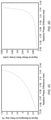
- FIG. 2B is a plot of simulated signal intensity as a function of the relative phase difference between a pair of interfering beams.
- FIG. 2C is a plot of simulated signal-to-background ratio (SBR) as a function of the relative phase difference between a pair of interfering beams.
- SBR signal-to-background ratio
- FIG. 2D is a plot of simulated signal-to-noise ratio (SNR) as a function of the relative phase difference between a pair of interfering beams.
- FIGS. 3A and 3B show a high-sensitivity phase cancellation microscope suitable for single-shot or real-time imaging of a neuronal action potential.
- FIG. 4A shows a high-sensitivity phase cancellation microscope suitable for single-shot or real-time imaging of a neuronal action potential.
- FIG. 4B shows a high-sensitivity phase cancellation microscope with a beam splitter-based interferometer.
- FIG. 4C shows a high-sensitivity phase cancellation microscope with a diffractive optical element (DOE)-based interferometer.
- DOE diffractive optical element
- FIG. 5 illustrates a process for imaging the phase of a neuronal action potential in a single-shot.
- Action potentials are generated in excitable cells. Neural cells produce propagating action potentials to transmit information. At rest, a neuron typically has a cell membrane potential of about ⁇ 70 mV.
- An action potential (a ‘spike’) is a temporary change in the neuron's membrane potential. If the neuron's membrane potential rises to a certain threshold, typically about ⁇ 55 mV, voltage-gated ion channels in the cell membrane open, causing positively charged ions to flow into the neuron and flipping the neuron's membrane potential from negative to positive. The membrane potential usually peaks at around +40 mV. Then these voltage-gated ion channels close and another type of ion channel opens, causing the membrane potential to decrease as positive ions leave the neuron. The membrane potential dips below its resting value for a brief (e.g., about 1 ms to 2 ms) refractory period, then returns to its resting value until a next triggering event occurs.
- a brief e.g.
- Our phase-cancellation microscope is sensitive enough for single-shot optical imaging of an action potential. It uses a laser or other coherent light source to illuminate a neuron with a beam of coherent light. As this beam propagates through the neuron, its optical wavefront undergoes an amplitude and spatial phase modulation. The beam exits the neuron and is split into first and second beams that propagate through first and second arms of an interferometer. The first and second beams interfere at the output of the interferometer to produce a spatial interference pattern whose amplitude encodes the spatial phase modulation imparted by the neuron. This spatial phase modulation is specific to each neuron and varies depending on the neuron's state, i.e., whether the neuron is spiking or not.
- Our phase-cancellation microscope measures the spatial phase modulation elicited by an action potential by canceling the background spatial phase modulation attributable to the resting (non-spiking) neuron. This is done by first measuring the spatial phase modulation that the resting neuron imparts on the optical wavefront of a coherent light beam.
- a spatial light modulator (SLM), deformable mirror, or other phase cancellation device in the microscope applies a complementary spatial phase modulation to the coherent beam that passed through the neuron, canceling the spatial phase imparted by the resting neuron and thereby generating a flat optical wavefront.
- SLM spatial light modulator
- the microscope measures only the spatial phase modulation attributable to the action potential on the otherwise flattened wavefront.
- the flattened field arrives at an interferometer, which can be a Mach-Zehnder or a Michelson interferometer, where a beam splitter or other component splits the incoming flattened field into two beams. Additional phase control is implemented to modify the relative phase, ⁇ , between these two beams using phase modulators placed in the two paths. Modulating the relative phase between the two beams changes the bias or DC offset of the interference signal at the output of the interferometer.
- the spatial filter can be, e.g., a pinhole placed in the Fourier plane of the interferometer, a suitably actuated digital micromirror device (DMD), spatial light modulator (SLM) or other spatial filter arrangement which enables us to implement a low-pass filter of desired cut-off frequency for one beam while letting the other beam pass.
- DMD digital micromirror device
- SLM spatial light modulator
- E ( x,y )
- (x, y) are the transverse axes of the detector
- and ⁇ 1,2 are the amplitudes and phases, respectively, of the first and second beams
- a represents the spatial frequency shift induced by the spatial filter arrangement to the first beam.
- ⁇ off is from about 10 ⁇ rad to about 10 mrad (e.g., about 10 ⁇ rad, 25 ⁇ rad, 50 ⁇ rad, 100 ⁇ rad (0.1 mrad), 0.2 mrad, 0.3 mrad, 0.4 mrad, 0.5 mrad, 1.0 mrad, 2.0 mrad, 3.0 mrad, 4.0 mrad, 5.0 mrad, 6.0 mrad, 7.0 mrad, 8.0 mrad, 9.0 mrad, or 10 mrad or any range between any of these values, e.g., 0.1-5 mrad), the camera operates in a low photon count regime in the absence of an optical signal related to the action potential. In other words, when the phase difference between the beams is shifted from ⁇ by at least ⁇ 0.1 mrad and by at most ⁇ 5 mrad, the camera operates in a sensitive regime.
- FIGS. 1A-1C illustrate the cancellation of phase modulation from a resting neuron.
- FIG. 1A shows a side view of a neuron (left), which is depicted as an oblate spheroid for simplicity.
- the neuron has a refractive index that is greater than the refractive index of the surrounding medium, which may be an extracellular matrix (e.g., a macromolecular network composed of proteins and polysaccharides); as a result, light propagating through the neuron travels along a longer optical path than light propagating through only the surrounding medium.
- extracellular matrix e.g., a macromolecular network composed of proteins and polysaccharides
- FIG. 1A shows the optical path length mismatch
- FIG. 1B shows the complementary spatial phase modulation ⁇ (x,y) that can be modulated on a beam propagating through the neuron with a deformable mirror, SLM or other suitable spatial phase modulator. If the neuron is at rest, this produces a flat optical wavefront shown in FIG. 1C .
- Exciting the neuron causes the neuron's shape and/or refractive index to change. This changes the optical path length mismatch between the neuron and the surrounding medium, so a beam propagating through the neuron experiences a spatial phase modulation ⁇ (x,y)+ ⁇ (x,y). Modulating this beam with the complementary spatial phase modulation ⁇ (x,y) cancels the static phase modulation associated with the resting neuron and leaves the phase modulation due to the excitation, ⁇ (x,y). This phase modulation due to the action potential can be detected by interfering the phase-modulated beam with a reference beam at a camera or detector array with a high dynamic range and low noise.
- FIG. 2A shows schematically the intensity, given in number of photons, of an interferometric signal as a function of the relative phase, ⁇ , between interfering beams as measured by one pixel or detector element of a camera or detector array.
- the interfering beams In a common path interferometer, the interfering beams have the same intensity, and interfere to produce a signal whose intensity varies as the cosine of the relative phase between the beams as shown in FIG. 2A .
- FIGS. 2B-2D show different simulated measures of the detected intensity as a function of the relative phase between the beams.
- FIGS. 2C and 2B show the base 10 logarithm of the signal-to-background ratio (SBR) and signal-to-noise ratio (SNR) in linear units, respectively, where the background and noise are given as, respectively:
- SBR signal-to-background ratio
- SNR signal-to-noise ratio
- FIGS. 3A and 3B illustrate an example of our high-sensitivity phase cancellation microscope 300 .
- the microscope 300 includes a coherent light source (here, a laser 310 ), an objective lens 316 , a phase cancellation module 320 , a common-path interferometer 330 with phase control between its arms, and a camera 340 .
- the laser 310 illuminates a sample neuron 314 with a beam of collimated, coherent light. This beam propagates through the sample neuron 314 , accumulating a spatially varying phase and amplitude modulation representing the sample neuron 314 and the surrounding medium.
- the objective lens 316 directs the transmitted beam to the phase cancellation module 320 , which flattens the phase of the beam's optical wavefront as discussed above with respect to FIGS. 1A-1C .
- the phase cancellation module 320 cancels substantially all of the spatial phase modulation picked up by the beam as it propagates through the sample 314 .
- the phase cancellation module 320 cancels substantially all of the spatial phase modulation associated with the resting neuron, leaving the beam's optical wavefront with the spatial phase modulation due to the action potential.
- the phase cancellation module 320 can also be placed elsewhere, e.g., between the laser 310 and neuron 314 and actuated in a similar fashion.
- a beam splitter 322 and lens 324 direct the flattened wavefront to the common-path interferometer 330 , which splits the beam into two beams and introduces a phase delay between the two beams. These two beams propagate back through the lens 324 , beam splitter 322 , and another lens 326 to the camera 340 , where they interfere to produce a spatial intensity pattern whose period depends on the spatially varying phase modulation that the beam accumulated while propagating through the sample 314 .
- FIG. 4A is a more detailed diagram of a high-sensitivity interferometric microscope 400 .
- a half-wave plate, linear polarizer assembly ⁇ /2 generates a 450 polarized beam from a laser 410 to illuminate a sample neuron S, which can be stimulated optically or electrically with a probe 452 .
- the probe 452 delivers this stimulation via a thin electrical lead or optical fiber that is in electromagnetic communication with the neuron S as shown in FIG. 4A .
- the laser wavelength can be 532 nm or longer, with longer wavelengths allowing for higher laser power due to lower absorption by the sample.
- the laser 410 can be a continuous-wave (cw) laser that illuminates the neuron S continuously or a pulsed laser that illuminates the neuron S with pulses of light in synchronization with stimulation of the neuron S by the probe 452 .
- cw continuous-wave
- An objective Obj collects the transmitted light and projects it onto a deformable mirror DM (SLM), placed in the conjugate image plane via a tube lens TL and a first beam splitter BS 1 .
- SLM deformable mirror DM
- the first beam splitter BS 1 and the deformable mirror DM form a phase cancellation module 420 that is controlled by a controller 450 , such as a computer or other processor.
- the controller 450 can determine the spatial phase profile of the resting neuron from a phase measurement by the microscope when the deformable mirror DM is flat (i.e., not actuated) and use that measurement to determine the complementary phase profile to impart with the deformable mirror DM (SLM) in order to cancel the resting neuron's spatial profile from a beam.
- the controller 450 actuates the deformable mirror DM (SLM) to reflect a beam with a flatter phase profile, thereby increasing the dynamic range of detection.
- the first beam splitter BS 1 directs the reflected beam to a second beam splitter BS 2 in a 4-f system including lenses L 1 and L 2 .
- Lens L 2 images the deformable mirror plane onto a Wollaston prism WP in a common path interferometer 430 a .
- the Wollaston prism WP splits the incoming light into two orthogonally polarized beams (vertical and horizontal polarizations).
- the two beams pass through respective phase modulators PM and through another lens L 3 .
- Each phase modulator PM may be, e.g., a glass plate that can be twisted or rotated to change the optical path length of the corresponding interferometer arm.
- the phase-delayed beams reflect off a reflective spatial filter M (e.g., a suitably actuated spatial light modulator) in the Fourier plane of lens L 3 .
- the spatial filter M removes high spatial frequencies from one of the beams in order to generate a plane wave for the transmitted spatial frequency portion at the camera detection plane for interference.
- the phase modulators PM allow control of the relative phase, ⁇ , between the two beams. These beams recombine in the Wollaston prism WP conjugate plane and travel collinearly through another 4-f system formed by lenses L 2 and L 4 onto a camera 440 (e.g., a 1.6-million-electron well-depth camera). Since the two beams are orthogonally polarized, an analyzer A oriented at 450 is placed before the camera 440 for interferometric detection. (The controller 450 uses the camera output to generate a single-shot phase image of the action potential.)
- FIGS. 4B and 4C show alternative versions of the microscope 400 a in FIG. 4A .
- the Wollaston prism WP is replaced by a simple beam splitter BS 3 in the common-path interferometer 430 b . While the beam splitter BS 3 could lead to a loss of 75% of the light, it would make it possible to eliminate the analyzer A before the camera 440 .
- the Wollaston prism WP is replaced by a diffractive optical element DOE in the common-path interferometer 430 c .
- the diffractive optical element DOE generates two beams (going from left to right in FIG. 4C ) and combines two beams into a single beam (from the right). Any analyzer can be eliminated from this microscope 400 c since both the beams coming back from the interferometer 430 c can have the same polarization.
- FIG. 5 shows a process 500 for acquiring a phase image of an action potential in a single shot using the microscope 400 shown in FIG. 4 or another similar microscope.
- the process 500 begins with adjusting the phase modulators PM in the interferometer arms so that the interferometric signal sensed by the camera is biased at the desired point (e.g., at a null or quadrature point as shown in FIG. 2A ) ( 502 ).
- the microscope acquires the spatial phase profile of the resting neuron ( 502 ). This can be done using the microscope 400 with the deformable mirror DM in a flat, unactuated state or another known state ( 504 ).
- the controller 450 or another suitable processor computes the complement of the spatial phase profile of the resting neuron from the measurement ( 506 ).
- Neurons can produce an action potential (‘spike’) spontaneously or can be stimulated to spike. Stimulated spiking allows for temporal onset control of the spiking and can be achieved, e.g., via electrical stimulation or optical stimulation (for optogenetically modified neurons) by the stimulation probe 452 .
- the controller 450 can command the probe 452 to stimulate the neuron, causing the neuron to spike.
- the laser 410 illuminates the spiking neuron with coherent light ( 508 ) to produce a beam whose wavefront has been spatially phase (and amplitude) modulated by the neuron ( 508 ).
- the controller 450 actuates the deformable mirror DM (SLM) to cancel the spatial profile of the resting neuron from this modulated wavefront ( 510 ), which is then subject to an interferometric measurement using the common-path interferometer 430 and the detector 440 ( 512 ) in a single shot. (The controller 450 uses this measurement to generate a phase image of the action potential ( 514 ).)
- SLM deformable mirror DM
- the camera 440 can run continuously or in a triggered mode.
- the laser 410 illuminates the neuron with a cw beam and the camera 440 records images of the neuron while it is resting and spiking as the spiking occurs, either spontaneously or in response to electrical or optical stimulation with the probe 452 .
- the camera 440 captures frames in synchronization with electrical or optical stimulation by the probe 452 , e.g., right before stimulation (while the neuron is resting) and right after stimulation (while the neuron is spiking).
- the laser 410 can illuminate the neuron with a cw beam or with pulses that are synchronized with the stimulation by the probe 452 , e.g., in response to control signals or pulses from the controller 450 .
- the camera frame rate can be 1 kHz or higher (e.g., 5 kHz, 10 kHz, 15 kHz, or 20 kHz).
- the steps of the process 500 can be performed in different orders.
- the relative phase difference between the interferometer arms ( 502 ) can be set or adjusted during or after measuring the resting neuron's phase profile ( 504 ).
- the resting neuron's phase profile can be canceled from the coherent beam ( 508 ) before the coherent beam illuminates the neuron ( 506 ) instead of after.
- inventive embodiments are presented by way of example only and that, within the scope of the appended claims and equivalents thereto, inventive embodiments may be practiced otherwise than as specifically described and claimed.
- inventive embodiments of the present disclosure are directed to each individual feature, system, article, material, kit, and/or method described herein.
- embodiments of designing and making the technology disclosed herein may be implemented using hardware, software or a combination thereof.
- the software code can be executed on any suitable processor or collection of processors, whether provided in a single computer or distributed among multiple computers.
- inventive concepts may be embodied as one or more methods, of which an example has been provided.
- the acts performed as part of the method may be ordered in any suitable way. Accordingly, embodiments may be constructed in which acts are performed in an order different than illustrated, which may include performing some acts simultaneously, even though shown as sequential acts in illustrative embodiments.
- a reference to “A and/or B”, when used in conjunction with open-ended language such as “comprising” can refer, in one embodiment, to A only (optionally including elements other than B); in another embodiment, to B only (optionally including elements other than A); in yet another embodiment, to both A and B (optionally including other elements); etc.
- the phrase “at least one,” in reference to a list of one or more elements, should be understood to mean at least one element selected from any one or more of the elements in the list of elements, but not necessarily including at least one of each and every element specifically listed within the list of elements and not excluding any combinations of elements in the list of elements.
- This definition also allows that elements may optionally be present other than the elements specifically identified within the list of elements to which the phrase “at least one” refers, whether related or unrelated to those elements specifically identified.
- “at least one of A and B” can refer, in one embodiment, to at least one, optionally including more than one, A, with no B present (and optionally including elements other than B); in another embodiment, to at least one, optionally including more than one, B, with no A present (and optionally including elements other than A); in yet another embodiment, to at least one, optionally including more than one, A, and at least one, optionally including more than one, B (and optionally including other elements); etc.
Landscapes
- Physics & Mathematics (AREA)
- General Physics & Mathematics (AREA)
- Engineering & Computer Science (AREA)
- Optics & Photonics (AREA)
- Chemical & Material Sciences (AREA)
- Analytical Chemistry (AREA)
- Theoretical Computer Science (AREA)
- Health & Medical Sciences (AREA)
- Life Sciences & Earth Sciences (AREA)
- Biomedical Technology (AREA)
- Biophysics (AREA)
- Artificial Intelligence (AREA)
- Computing Systems (AREA)
- Computational Linguistics (AREA)
- Data Mining & Analysis (AREA)
- Evolutionary Computation (AREA)
- General Health & Medical Sciences (AREA)
- Molecular Biology (AREA)
- Neurology (AREA)
- General Engineering & Computer Science (AREA)
- Mathematical Physics (AREA)
- Software Systems (AREA)
- Automation & Control Theory (AREA)
- Multimedia (AREA)
- Microscoopes, Condenser (AREA)
Abstract
Description
E(x,y)=|E 1 |e i[ϕ
where (x, y) are the transverse axes of the detector; |E1,2| and ϕ1,2 are the amplitudes and phases, respectively, of the first and second beams; and a represents the spatial frequency shift induced by the spatial filter arrangement to the first beam.
S=(E 1 +E 2)2=2E 0 2[1+cos(δϕ+Δϕ)]
B=2E 0 2[1+cos(Δϕ)]
N=√{square root over (2)}E 0√{square root over (1+cos(δϕ+Δϕ))}.
Claims (20)
Priority Applications (1)
| Application Number | Priority Date | Filing Date | Title |
|---|---|---|---|
| US17/140,558 US11255656B2 (en) | 2020-03-02 | 2021-01-04 | Phase cancellation microscopy |
Applications Claiming Priority (2)
| Application Number | Priority Date | Filing Date | Title |
|---|---|---|---|
| US202062983800P | 2020-03-02 | 2020-03-02 | |
| US17/140,558 US11255656B2 (en) | 2020-03-02 | 2021-01-04 | Phase cancellation microscopy |
Publications (2)
| Publication Number | Publication Date |
|---|---|
| US20210270595A1 US20210270595A1 (en) | 2021-09-02 |
| US11255656B2 true US11255656B2 (en) | 2022-02-22 |
Family
ID=77463076
Family Applications (1)
| Application Number | Title | Priority Date | Filing Date |
|---|---|---|---|
| US17/140,558 Active US11255656B2 (en) | 2020-03-02 | 2021-01-04 | Phase cancellation microscopy |
Country Status (2)
| Country | Link |
|---|---|
| US (1) | US11255656B2 (en) |
| WO (1) | WO2021178041A1 (en) |
Cited By (1)
| Publication number | Priority date | Publication date | Assignee | Title |
|---|---|---|---|---|
| US20190318233A1 (en) * | 2018-04-14 | 2019-10-17 | International Business Machines Corporation | Optical synapse |
Citations (8)
| Publication number | Priority date | Publication date | Assignee | Title |
|---|---|---|---|---|
| US20130181143A1 (en) | 2011-07-14 | 2013-07-18 | Howard Hughes Medical Institute | Microscopy with adaptive optics |
| US20150004637A1 (en) * | 2011-11-23 | 2015-01-01 | President And Fellows Of Harvard College | Systems and methods for imaging at high spatial and/or temporal precision |
| US20150233820A1 (en) * | 2012-07-17 | 2015-08-20 | École Polytechnique Fédérale de Lausanne | Device and method for measuring and imaging second harmonic and multi-photon generation scattered radiation |
| US20150330892A1 (en) * | 2012-12-14 | 2015-11-19 | Vala Sciences, Inc. | Analysis of Action Potentials, Transients, and Ion Flux in Excitable Cells |
| US20180224644A1 (en) | 2017-02-09 | 2018-08-09 | Howard Hughes Medical Institute | Video-rate volumetric functional imaging of the brain at synaptic resolution |
| US10564042B1 (en) | 2016-04-18 | 2020-02-18 | The Government Of The United States Of America, As Represented By The Secretary Of The Navy | Advantages of spatial demodulation in interferometric optical sensing applications |
| US20200069233A1 (en) * | 2016-11-15 | 2020-03-05 | Cornell University | Adaptive illumination apparatus, method, and applications |
| US20200342205A1 (en) * | 2018-01-26 | 2020-10-29 | Massachusetts Institute Of Technology | Systems and methods to reduce scattering in temporal focusing multiphoton microscopy |
-
2021
- 2021-01-04 US US17/140,558 patent/US11255656B2/en active Active
- 2021-01-04 WO PCT/US2021/012058 patent/WO2021178041A1/en not_active Ceased
Patent Citations (8)
| Publication number | Priority date | Publication date | Assignee | Title |
|---|---|---|---|---|
| US20130181143A1 (en) | 2011-07-14 | 2013-07-18 | Howard Hughes Medical Institute | Microscopy with adaptive optics |
| US20150004637A1 (en) * | 2011-11-23 | 2015-01-01 | President And Fellows Of Harvard College | Systems and methods for imaging at high spatial and/or temporal precision |
| US20150233820A1 (en) * | 2012-07-17 | 2015-08-20 | École Polytechnique Fédérale de Lausanne | Device and method for measuring and imaging second harmonic and multi-photon generation scattered radiation |
| US20150330892A1 (en) * | 2012-12-14 | 2015-11-19 | Vala Sciences, Inc. | Analysis of Action Potentials, Transients, and Ion Flux in Excitable Cells |
| US10564042B1 (en) | 2016-04-18 | 2020-02-18 | The Government Of The United States Of America, As Represented By The Secretary Of The Navy | Advantages of spatial demodulation in interferometric optical sensing applications |
| US20200069233A1 (en) * | 2016-11-15 | 2020-03-05 | Cornell University | Adaptive illumination apparatus, method, and applications |
| US20180224644A1 (en) | 2017-02-09 | 2018-08-09 | Howard Hughes Medical Institute | Video-rate volumetric functional imaging of the brain at synaptic resolution |
| US20200342205A1 (en) * | 2018-01-26 | 2020-10-29 | Massachusetts Institute Of Technology | Systems and methods to reduce scattering in temporal focusing multiphoton microscopy |
Non-Patent Citations (12)
| Title |
|---|
| Akkin et al., "Detection of neural action potentials using optical coherence tomography: intensity and phase measurements with and without dyes." Frontiers in Neuroenergetics 2 (2010): 22. 10 pages. |
| Batabyal et al., "Label-free optical detection of action potential in mammalian neurons." Biomedical Optics Express 8.8 (2017): 3700-3713. |
| Cohen et al., "Light scattering and birefringence changes during nerve activity." Nature 218.5140 (1968): 438-441. |
| Cohen, "Changes in neuron structure during action potential propagation and synaptic transmission." Physiological Reviews 53.2 (1973): 373-418. |
| Hosseini et al., "Pushing phase and amplitude sensitivity limits in interferometric microscopy." Optics Letters 41.7 (2016): 1656-1659. |
| International Search Report and Written Opinion in International Patent Application No. PCT/US2021/012058 dated Mar. 23, 2021, 16 pages. |
| Ling et al., "Full-field interferometric imaging of propagating action potentials." Light: Science & Applications 7.1 (2018): 1-11. |
| Ling et al., "High-speed interferometric imaging reveals dynamics of neuronal deformation during the action potential", Proceedings of the National Academy of Sciences, 0027-8424 (2020). 8 pages. |
| Nikolenko, Volodymyr et al. "Spatial Light Modulator Microscopy". Cold Spring Harb Protoc; 2013; doi: 10.1101/pdb.top079517, pp. 1132-1141. (Year: 2013). * |
| Packer, Adam M. et al. "Simultaneous all-optical manipulation and recording of neural circuit activity with cellular resolution in vivo". Nature Methods, vol. 12, No. 2, Feb. 2015, pp. 140-146. (Year: 2015). * |
| Popescu et al., "Diffraction phase microscopy for quantifying cell structure and dynamics", Optics Letters, 31(6), pp. 775-777 (2006). |
| Shtrahman, Matthew et al. "Multifocal Fluorescence Microscope for Fast Optical Recordings of Neuronal Action Potentials". Biophysical Journal, vol. 108, No. 3, Feb. 2015, pp. 520-529. (Year: 2015). * |
Cited By (2)
| Publication number | Priority date | Publication date | Assignee | Title |
|---|---|---|---|---|
| US20190318233A1 (en) * | 2018-04-14 | 2019-10-17 | International Business Machines Corporation | Optical synapse |
| US11521055B2 (en) * | 2018-04-14 | 2022-12-06 | International Business Machines Corporation | Optical synapse |
Also Published As
| Publication number | Publication date |
|---|---|
| US20210270595A1 (en) | 2021-09-02 |
| WO2021178041A1 (en) | 2021-09-10 |
Similar Documents
| Publication | Publication Date | Title |
|---|---|---|
| JP5306075B2 (en) | Imaging apparatus and imaging method using optical coherence tomography | |
| Müller et al. | Dispersion pre‐compensation of 15 femtosecond optical pulses for high‐numerical‐aperture objectives | |
| US8334982B2 (en) | Systems and methods for phase measurements | |
| CN100590421C (en) | System and method for phase measurement | |
| US7365858B2 (en) | Systems and methods for phase measurements | |
| US8830573B2 (en) | Optical phase conjugation 4Pi microscope | |
| US9164479B2 (en) | Systems and methods of dual-plane digital holographic microscopy | |
| Liu et al. | Quantum enhancement of phase sensitivity for the bright-seeded SU (1, 1) interferometer with direct intensity detection | |
| US20060033933A1 (en) | Method and device for wave-front sensing | |
| CA2529942A1 (en) | Systems and methods for phase measurements | |
| Hu et al. | Optical excitation and detection of neuronal activity | |
| Yepiz-Graciano et al. | Quantum optical coherence microscopy for bioimaging applications | |
| CN107037031A (en) | The confocal CARS micro-spectrometers method and device of reflection type differential | |
| CN106990095B (en) | Reflection-type confocal CARS micro-spectrometer method and apparatus | |
| US11255656B2 (en) | Phase cancellation microscopy | |
| CN112595699B (en) | An ultrafast dynamic imaging system and method based on single molecular quantum coherence | |
| US11221293B2 (en) | Two-dimensional second harmonic dispersion interferometer | |
| CN110873956B (en) | An ultra-high-speed orthogonal polarization imaging device and method | |
| US8502987B1 (en) | Method and apparatus for measuring near-angle scattering of mirror coatings | |
| Brakenhoff et al. | Femtosecond pulse width control in microscopy by two‐photon absorption autocorrelation | |
| JPH1123372A (en) | Light wave coherence imaging method and apparatus | |
| JP2004150965A (en) | Disturbance measuring device and high-precision optical interferometer in optical interferometer | |
| Lyzwa et al. | High-Sensitivity Phase Microscopy for Neural Activity | |
| WO2009106358A1 (en) | Method and apparatus for spectral optical coherence tomography | |
| Akcay et al. | Dispersion manipulation in optical coherence tomography with Fourier-domain optical delay line |
Legal Events
| Date | Code | Title | Description |
|---|---|---|---|
| FEPP | Fee payment procedure |
Free format text: ENTITY STATUS SET TO UNDISCOUNTED (ORIGINAL EVENT CODE: BIG.); ENTITY STATUS OF PATENT OWNER: SMALL ENTITY |
|
| FEPP | Fee payment procedure |
Free format text: ENTITY STATUS SET TO SMALL (ORIGINAL EVENT CODE: SMAL); ENTITY STATUS OF PATENT OWNER: SMALL ENTITY |
|
| STPP | Information on status: patent application and granting procedure in general |
Free format text: DOCKETED NEW CASE - READY FOR EXAMINATION |
|
| AS | Assignment |
Owner name: MASSACHUSETTS INSTITUTE OF TECHNOLOGY, MASSACHUSETTS Free format text: ASSIGNMENT OF ASSIGNORS INTEREST;ASSIGNORS:SO, PETER T. C.;YAQOOB, ZAHID;LYZWA, DOMINIKA;AND OTHERS;SIGNING DATES FROM 20210208 TO 20210819;REEL/FRAME:057410/0105 |
|
| STPP | Information on status: patent application and granting procedure in general |
Free format text: NOTICE OF ALLOWANCE MAILED -- APPLICATION RECEIVED IN OFFICE OF PUBLICATIONS |
|
| STPP | Information on status: patent application and granting procedure in general |
Free format text: PUBLICATIONS -- ISSUE FEE PAYMENT VERIFIED |
|
| STCF | Information on status: patent grant |
Free format text: PATENTED CASE |
|
| AS | Assignment |
Owner name: NATIONAL INSTITUTES OF HEALTH (NIH), U.S. DEPT. OF HEALTH AND HUMAN SERVICES (DHHS), U.S. GOVERNMENT, MARYLAND Free format text: CONFIRMATORY LICENSE;ASSIGNOR:MASSACHUSETTS INSTITUTE OF TECHNOLOGY;REEL/FRAME:065380/0431 Effective date: 20210218 |
|
| MAFP | Maintenance fee payment |
Free format text: PAYMENT OF MAINTENANCE FEE, 4TH YR, SMALL ENTITY (ORIGINAL EVENT CODE: M2551); ENTITY STATUS OF PATENT OWNER: SMALL ENTITY Year of fee payment: 4 |