US11253284B2 - Instrument with a detachable motor drive assembly, telescope and cutter tube assembly - Google Patents
Instrument with a detachable motor drive assembly, telescope and cutter tube assembly Download PDFInfo
- Publication number
- US11253284B2 US11253284B2 US16/464,420 US201716464420A US11253284B2 US 11253284 B2 US11253284 B2 US 11253284B2 US 201716464420 A US201716464420 A US 201716464420A US 11253284 B2 US11253284 B2 US 11253284B2
- Authority
- US
- United States
- Prior art keywords
- assembly
- cutter
- instrument
- gear
- tube
- Prior art date
- Legal status (The legal status is an assumption and is not a legal conclusion. Google has not performed a legal analysis and makes no representation as to the accuracy of the status listed.)
- Active, expires
Links
Images


Classifications
-
- A—HUMAN NECESSITIES
- A61—MEDICAL OR VETERINARY SCIENCE; HYGIENE
- A61B—DIAGNOSIS; SURGERY; IDENTIFICATION
- A61B17/00—Surgical instruments, devices or methods
- A61B17/32—Surgical cutting instruments
- A61B17/320016—Endoscopic cutting instruments, e.g. arthroscopes, resectoscopes
- A61B17/32002—Endoscopic cutting instruments, e.g. arthroscopes, resectoscopes with continuously rotating, oscillating or reciprocating cutting instruments
-
- A—HUMAN NECESSITIES
- A61—MEDICAL OR VETERINARY SCIENCE; HYGIENE
- A61B—DIAGNOSIS; SURGERY; IDENTIFICATION
- A61B17/00—Surgical instruments, devices or methods
- A61B17/00234—Surgical instruments, devices or methods for minimally invasive surgery
- A61B2017/00238—Type of minimally invasive operation
- A61B2017/00274—Prostate operation, e.g. prostatectomy, turp, bhp treatment
-
- A—HUMAN NECESSITIES
- A61—MEDICAL OR VETERINARY SCIENCE; HYGIENE
- A61B—DIAGNOSIS; SURGERY; IDENTIFICATION
- A61B17/00—Surgical instruments, devices or methods
- A61B2017/0046—Surgical instruments, devices or methods with a releasable handle; with handle and operating part separable
-
- A—HUMAN NECESSITIES
- A61—MEDICAL OR VETERINARY SCIENCE; HYGIENE
- A61B—DIAGNOSIS; SURGERY; IDENTIFICATION
- A61B17/00—Surgical instruments, devices or methods
- A61B2017/00477—Coupling
-
- A—HUMAN NECESSITIES
- A61—MEDICAL OR VETERINARY SCIENCE; HYGIENE
- A61B—DIAGNOSIS; SURGERY; IDENTIFICATION
- A61B17/00—Surgical instruments, devices or methods
- A61B17/32—Surgical cutting instruments
- A61B17/320016—Endoscopic cutting instruments, e.g. arthroscopes, resectoscopes
- A61B17/32002—Endoscopic cutting instruments, e.g. arthroscopes, resectoscopes with continuously rotating, oscillating or reciprocating cutting instruments
- A61B2017/320024—Morcellators, e.g. having a hollow cutting tube with an annular cutter for morcellating and removing tissue
-
- A—HUMAN NECESSITIES
- A61—MEDICAL OR VETERINARY SCIENCE; HYGIENE
- A61B—DIAGNOSIS; SURGERY; IDENTIFICATION
- A61B90/00—Instruments, implements or accessories specially adapted for surgery or diagnosis and not covered by any of the groups A61B1/00 - A61B50/00, e.g. for luxation treatment or for protecting wound edges
- A61B90/08—Accessories or related features not otherwise provided for
- A61B2090/0813—Accessories designed for easy sterilising, i.e. re-usable
Definitions
- the present invention relates, in general, to an instrument and more particularly, to a medical instrument comprising of a motor drive assembly detachable from a handle assembly and detachable from a gear assembly.
- the gear assembly of the medical instrument is inside the handle assembly and further the medical instrument includes a standard telescope which is detachable from the instrument and a cutter/blade assembly detachable from an outer sheath. Further, outer sheath can be detached from handle assembly.
- BPH benign prostatic hyperplasia
- the instrument shall also allow cleaning and/or sterilizing and/or autoclaving of the handle assembly and/or the gear assembly after the motor assembly is detached.
- the object of the invention is to provide a motor drive assembly that is detachable from a handle assembly of an instrument and also detachable from a gear assembly of the instrument for the purpose of replacing a motor drive assembly with a new motor drive assembly when the motor drive assembly is damaged due to multiple uses.
- Another object of the invention is to provide a detachable motor drive assembly from the handle assembly and the gear assembly for the purpose of reusing the motor drive assembly after cleaning and/or sterilizing and/or autoclaving it such that it is clean of all contaminants before use.
- Yet another object of the invention is to enable cleaning and/or sterilizing and/or autoclaving the handle assembly and/or the gear assembly which can get contaminated by contaminants and/or blood and/or tissue due to multiple use and such that it can be reused.
- Yet another object of the invention is that, if the handle assembly wears, then the handle assembly can be replaced with a new handle assembly.
- Yet another object of the invention is to enable detachment of the blade or cutter tube from an outer tube of the instrument, replace either of them or both with a new one if it wears due to multiple uses.
- Another object of the invention is to enable detachment of the cutter/blade tube from outer tube to clean and/or sterilize and/or autoclave the blade/cutter tube and/or outer tube so that it is clean of all contaminants and/or blood and/or tissue so that it can be reused after cleaning and/or sterilizing and/or autoclaving.
- Another object of the invention is to provide a telescope which is in a straight alignment with the blade/cutter tube assembly and that can be detached from the instrument and replaced with a new one.
- Any standard telescope can be used as a replacement to older one. In case of damage or if the telescope wears out there is no need to replace complete device. It therefore allows replacement of only the telescope rather than discarding the whole device.
- Yet another object of the invention is to provide the telescope which is in a straight alignment with the blade/cutter tube assembly that can also be cleaned and/or sterilized and/or autoclaved and reused so that it is clean of all contaminants and also provides a clear vision.
- This invention discloses an instrument 1 , which is a morcellator, particularly a urological morcellator with a motor drive assembly 2 that is detachable from a handle assembly 3 and detachable from a gear assembly 5 for the purpose of reusing or replacing the motor drive assembly.
- a telescope 17 is provided in a straight alignment to a cutter/blade tube assembly 19 .
- a button 23 is rotated the telescope 17 is detachable from the instrument. This telescope is in straight alignment to the cutter/blade tube assembly 19 .
- This provides an advantage to detach the blade/cutter tube from the outer tube, replace both or either one with a new one if it wears due to multiple use or to detach the cutter/blade tube and outer tube, clean and/or sterilize and/or autoclave it so that it is clean of all contaminants and/or blood and/or tissue so that it can be reused after sterilizing and/or cleaning and/or autoclaving.
- FIG. 12 illustrates a sectional view of the gear assembly 5 along the line B-B shown in FIG. 11 that is present inside a gear box casing 7 with internal parts comprising of an at least one first bevel gear 8 and an at least one second bevel gear 9 , an at least one first spur/helical gear 10 and an at least one second spur/helical gear 11 . Any combination of the gear can be used to achieve the motion.
- the gear assembly 5 further comprises of an at least one first bearing-bush 13 , an at least one second bearing/bush 14 in alignment with at least one first gear shaft 15 .
- An at least one third bearing/bush 16 holds the second spur/helical gear 11 . This motion can also be achieved by worm wheel mechanism.
- FIG. 1 illustrates the top view of the instrument.
- FIG. 2 illustrates the bottom view of the instrument.
- FIG. 3 illustrates the left hand view of the instrument.
- FIG. 4 illustrates the right hand view of the instrument.
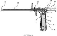
- FIG. 6 illustrates the sectional view of the instrument along the line A-A displayed in FIG. 5 .
- FIG. 7 illustrates a button when pressed the outer sheath can be detached which can be removed out completely.
- FIG. 8 illustrates cutter/blade tube inside the cutter/blade tube assembly.
- FIG. 9 illustrates button for detaching the motor drive assembly present inside the casing from the gear assembly and the handle assembly.
- FIG. 10 illustrates a gear assembly inside a gear box casing.
- FIG. 12 illustrates a sectional view of the gear assembly along the line B-B shown in FIG. 11 .
- FIG. 13 illustrates exploded view of handle assembly with cutter/blade tube with at least one second gear shaft that connects with the at least one square connector of cutter/blade tube.
- FIG. 14 illustrates the detail view of the gear assembly where the at least one square connector of the cutter/blade tube couples with at least one second gear shaft.
- FIG. 15 illustrates a top view of the cutter/blade part of the cutter/blade tube displaying sharp teeth like projections 20 in the central oval region for cutting purpose of the tissue.
- FIG. 16 illustrates a front view of the cutter/blade part of the cutter/blade tube displaying a concave region 21 on both top and bottom side.
- FIG. 17 illustrates a top view of another embodiment of the cutter/blade part of the cutter/blade tube displaying the sharp edges 22 at the sides.
- FIG. 18 illustrates a front view of FIG. 17 of the cutter/blade part with sharp edges on a rectangular area on the cutter part.
- FIG. 1 illustrates the top view of the instrument.
- FIG. 2 illustrates the bottom view of the instrument.
- FIG. 3 illustrates the left hand view of the instrument.
- FIG. 4 illustrates the right hand view of the instrument.
- FIG. 6 illustrates the sectional view of the instrument along the line A-A displayed in FIG. 5 .
- the invention discloses a medical instrument 1 which is a morcellator, particularly a urological morcellator, with a motor drive assembly 2 that is detachable from a handle assembly 3 and detachable from a gear assembly 5 for the purpose of reusing or replacing the motor drive assembly.
- FIG. 6 illustrates a motor drive assembly 2 with an integrated square connector 4 inside a casing 25 of the instrument giving it mechanical advantage of direct drive leading to lesser mechanical loss. Wire cable can be used instead of gear mechanism.
- the purpose of the invention is to provide a motor drive assembly that is detachable from the handle assembly and also detachable from the gear assembly for the purpose of replacing the motor drive assembly with a new motor drive assembly when the motor drive assembly damages due to multiple uses.
- Another purpose of the invention is to provide a detachable motor drive assembly from the handle assembly and the gear assembly for the purpose of reusing the motor drive assembly after cleaning and/or sterilizing and/or autoclaving it such that it is clean of all contaminants before use.
- a telescope 17 is provided in straight alignment to a cutter/blade tube assembly 19 of the instrument.
- a button 23 is rotated the telescope 17 is detachable from the instrument.
- This telescope is provided in straight alignment to the cutter/blade tube assembly 19 .
- the telescope can be in any other angle to the instrument.
- the present invention provides a telescope which is in a straight alignment with the cutter tube and that can be detached from the instrument and replaced with a new one. Any standard telescope can be used as a replacement to older one.
- the telescope can also be cleaned and/or sterilized and/or autoclaved and reused so that it is clean of all contaminants and also provides a clear vision.
- This provides the advantage to detach the blade/cutter tube from the outer tube, replace both or either one with a new one if it wears due to multiple use or to detach the cutter/blade tube and outer tube, clean and/or sterilize and/or autoclave it so that it is clean of all contaminants and/or blood and/or tissue so that it can be reused after sterilizing and/or cleaning and/or autoclaving.
- FIG. 8 illustrates a cutter/blade tube 31 inside the cutter/blade tube assembly 19 where the cutter/blade tube 31 rotates inside the outer tube 30 and a tissue shears/cuts between sharp edge of cutter/blade part of the cutter/blade tube 31 and front concave part of an outer tube 30 .
- Front concave part of outer tube 30 is shown in detail view 32 .
- Front cutter/blade part of inner cutter/blade tube 31 is shown in detail view 28 .
- Back square part of inner cutter/blade tube 31 is shown in detail view 29 .
- FIG. 9 illustrates a button 6 for detaching the motor drive assembly 2 present inside the casing 25 from the gear assembly 5 and the handle assembly 3 (as illustrated in FIG. 06 ).
- the detachable motor drive assembly provides the advantage of replacing the old motor drive assembly with a new motor drive assembly when it gets damaged after multiple uses.
- the motor drive assembly after detachment can be cleaned and/or sterilized and/or autoclaved such that it is clean of all the contaminants and can be reused.
- the handle assembly and/or the gear assembly can be cleaned and/or sterilized and/or autoclaved and reused such that it is clear of contaminants and/or blood and/or tissue.
- FIG. 10 illustrates a gear assembly 5 inside a gear box casing 7 .
- FIG. 12 illustrates a sectional view of the gear assembly 5 along the line B-B shown in FIG. 11 that is present inside the gear box casing 7 with internal parts comprising of an at least one first bevel gear 8 and an at least one second bevel gear 9 , an at least one first spur/helical gear 10 and an at least one second spur/helical gear 11 . Any combination of the gear can be used to achieve the motion.
- the gear assembly 5 further comprises of at least one first bearing/bush 13 and at least one second bearing/bush 14 in alignment with at least one first gear shaft 15 . Further, at least one third bearing/bush 16 holds the second spur/helical gear 11 . This motion can also be achieved by worm wheel mechanism.
- the opening 12 may be square or any other shape.
- the integrated square connector 4 (shown in FIG. 6 ) is connected to an opening 12 in the first bevel gear 8 which can be detached by pressing button 6 to detach the motor drive assembly 2 .
- the flexible shaft can be attached to rotate the cutter.
- FIG. 13 illustrates an exploded view of handle assembly with cutter/blade tube with at least one second gear shaft 35 .
- At least one square connector 39 of cutter/blade tube, shown in detail view 29 of FIG. 8 couples with an at least one square cavity 38 of second gear shaft 35 .
- At least one fourth bearing 34 connects with the at least one second gear shaft 35 of assembly.
- FIG. 14 illustrates the detail view of the gear assembly where the at least one square connector 39 of the cutter/blade tube couples with at least one second gear shaft 35 due to its square profile and positively engages with each other for rotational motion of the cutter/blade tube about its axis.
- FIG. 15 illustrates a top view of the cutter/blade part of the cutter/blade tube displaying sharp teeth like projections 20 in the central oval region for cutting purpose of the tissue.
- FIG. 16 illustrates a front view of the cutter/blade part of the cutter/blade tube displaying a concave region 21 on both top and bottom side.
- FIG. 17 illustrates a top view of another embodiment of the cutter/blade part of the cutter/blade tube displaying the sharp edges 22 at the sides.
- FIG. 18 illustrates a front view of FIG. 17 of the cutter/blade part with sharp edges on a rectangular area on the cutter part.
- the instrument can be used without limitation in gynecological surgeries, laparoscopic surgeries, hysterectomy surgeries, benign prostatic hyperplasia (BPH) surgeries and other similar such surgeries.
Landscapes
- Health & Medical Sciences (AREA)
- Surgery (AREA)
- Life Sciences & Earth Sciences (AREA)
- Biomedical Technology (AREA)
- Nuclear Medicine, Radiotherapy & Molecular Imaging (AREA)
- Engineering & Computer Science (AREA)
- Orthopedic Medicine & Surgery (AREA)
- Heart & Thoracic Surgery (AREA)
- Medical Informatics (AREA)
- Molecular Biology (AREA)
- Animal Behavior & Ethology (AREA)
- General Health & Medical Sciences (AREA)
- Public Health (AREA)
- Veterinary Medicine (AREA)
- Surgical Instruments (AREA)
Abstract
Description
Claims (7)
Applications Claiming Priority (3)
| Application Number | Priority Date | Filing Date | Title |
|---|---|---|---|
| IN201621042633 | 2016-12-14 | ||
| IN201621042633 | 2016-12-14 | ||
| PCT/IN2017/050584 WO2018109783A1 (en) | 2016-12-14 | 2017-12-10 | Instrument with a detachable motor drive assembly, telescope and cutter tube assembly |
Publications (2)
| Publication Number | Publication Date |
|---|---|
| US20210113233A1 US20210113233A1 (en) | 2021-04-22 |
| US11253284B2 true US11253284B2 (en) | 2022-02-22 |
Family
ID=62558133
Family Applications (1)
| Application Number | Title | Priority Date | Filing Date |
|---|---|---|---|
| US16/464,420 Active 2038-04-15 US11253284B2 (en) | 2016-12-14 | 2017-12-10 | Instrument with a detachable motor drive assembly, telescope and cutter tube assembly |
Country Status (2)
| Country | Link |
|---|---|
| US (1) | US11253284B2 (en) |
| WO (1) | WO2018109783A1 (en) |
Citations (3)
| Publication number | Priority date | Publication date | Assignee | Title |
|---|---|---|---|---|
| US8100928B2 (en) * | 2006-08-10 | 2012-01-24 | Ethicon, Inc. | Morcellator with detachable handle |
| US20130324882A1 (en) * | 2012-05-30 | 2013-12-05 | Devicor Medical Products, Inc. | Control for biopsy device |
| US20150305772A1 (en) * | 2014-04-25 | 2015-10-29 | Womens Health and Wellness, PLLC. | Morcellation containment system |
Family Cites Families (2)
| Publication number | Priority date | Publication date | Assignee | Title |
|---|---|---|---|---|
| US6156049A (en) * | 1997-04-11 | 2000-12-05 | Coherent Inc. | Method and apparatus for transurethral resection of the prostate |
| DE102010020927A1 (en) * | 2010-05-10 | 2011-11-10 | Karl Storz Gmbh & Co. Kg | Medical instrument with removable handle |
-
2017
- 2017-12-10 US US16/464,420 patent/US11253284B2/en active Active
- 2017-12-10 WO PCT/IN2017/050584 patent/WO2018109783A1/en not_active Ceased
Patent Citations (3)
| Publication number | Priority date | Publication date | Assignee | Title |
|---|---|---|---|---|
| US8100928B2 (en) * | 2006-08-10 | 2012-01-24 | Ethicon, Inc. | Morcellator with detachable handle |
| US20130324882A1 (en) * | 2012-05-30 | 2013-12-05 | Devicor Medical Products, Inc. | Control for biopsy device |
| US20150305772A1 (en) * | 2014-04-25 | 2015-10-29 | Womens Health and Wellness, PLLC. | Morcellation containment system |
Also Published As
| Publication number | Publication date |
|---|---|
| US20210113233A1 (en) | 2021-04-22 |
| WO2018109783A1 (en) | 2018-06-21 |
Similar Documents
| Publication | Publication Date | Title |
|---|---|---|
| US5681262A (en) | Endoscope and tool therefore | |
| EP2883508B1 (en) | Tissue shaving device having a fluid removal path | |
| CN106999297B (en) | Internally illuminated surgical probe | |
| Badr-El-Dine et al. | Instrumentation and technologies in endoscopic ear surgery | |
| US20190150902A1 (en) | Invasive instrument for treating vessels | |
| EP3773235A1 (en) | Fully integrated endoscope with biopsy capabilities and methods of use | |
| US20240315722A1 (en) | Rotary instruments and methods for intrauterine tissue resection | |
| WO2014048149A1 (en) | Disposable endoscope sheath | |
| US20100121141A1 (en) | Endoscopic cutting and debriding device mounted on a flexible and maneuverable tube employing a fluid-driven turbine | |
| US8840595B2 (en) | Removable suction assembly for medical handpieces | |
| HK1231362A1 (en) | Surgical instrument | |
| US8840596B2 (en) | Removable suction assembly for medical handpieces | |
| TW201601678A (en) | OCT transparent surgical instruments and methods | |
| CN109620358A (en) | Device for cutting tissue | |
| JP2023063277A (en) | Embedded laser fiber for aspiration lithorectomy | |
| JPS60142842A (en) | Surgical incision instrument | |
| US11253284B2 (en) | Instrument with a detachable motor drive assembly, telescope and cutter tube assembly | |
| US20160166433A1 (en) | Surgical instrument | |
| US12496737B2 (en) | Rotary trimmer | |
| JP2018122096A (en) | Surgical cutting instrument having an extended blade | |
| KR20180092322A (en) | Portable surgical device with constriction | |
| CN204618403U (en) | Tissue cutting and reducing mechanism and operation mirror | |
| JPH05103756A (en) | Endoscope | |
| Geisthoff | Technology of sialendoscopy | |
| JPH0243501B2 (en) |
Legal Events
| Date | Code | Title | Description |
|---|---|---|---|
| AS | Assignment |
Owner name: XCELLANCE MEDICAL TECHNOLOGIES PVT. LTD, INDIA Free format text: ASSIGNMENT OF ASSIGNORS INTEREST;ASSIGNOR:NARKHEDE, PRADIP BARSU;REEL/FRAME:049292/0720 Effective date: 20190525 |
|
| FEPP | Fee payment procedure |
Free format text: ENTITY STATUS SET TO UNDISCOUNTED (ORIGINAL EVENT CODE: BIG.); ENTITY STATUS OF PATENT OWNER: SMALL ENTITY |
|
| FEPP | Fee payment procedure |
Free format text: ENTITY STATUS SET TO SMALL (ORIGINAL EVENT CODE: SMAL); ENTITY STATUS OF PATENT OWNER: SMALL ENTITY |
|
| STPP | Information on status: patent application and granting procedure in general |
Free format text: RESPONSE TO NON-FINAL OFFICE ACTION ENTERED AND FORWARDED TO EXAMINER |
|
| STPP | Information on status: patent application and granting procedure in general |
Free format text: FINAL REJECTION MAILED |
|
| STPP | Information on status: patent application and granting procedure in general |
Free format text: RESPONSE AFTER FINAL ACTION FORWARDED TO EXAMINER |
|
| STPP | Information on status: patent application and granting procedure in general |
Free format text: NOTICE OF ALLOWANCE MAILED -- APPLICATION RECEIVED IN OFFICE OF PUBLICATIONS |
|
| STPP | Information on status: patent application and granting procedure in general |
Free format text: PUBLICATIONS -- ISSUE FEE PAYMENT VERIFIED |
|
| STCF | Information on status: patent grant |
Free format text: PATENTED CASE |
|
| MAFP | Maintenance fee payment |
Free format text: PAYMENT OF MAINTENANCE FEE, 4TH YR, SMALL ENTITY (ORIGINAL EVENT CODE: M2551); ENTITY STATUS OF PATENT OWNER: SMALL ENTITY Year of fee payment: 4 |