US11252855B2 - Agricultural seed treatment control system for liquid agrochemicals - Google Patents
Agricultural seed treatment control system for liquid agrochemicals Download PDFInfo
- Publication number
- US11252855B2 US11252855B2 US16/110,944 US201816110944A US11252855B2 US 11252855 B2 US11252855 B2 US 11252855B2 US 201816110944 A US201816110944 A US 201816110944A US 11252855 B2 US11252855 B2 US 11252855B2
- Authority
- US
- United States
- Prior art keywords
- liquid
- seed treatment
- mass flow
- signal
- treatment
- Prior art date
- Legal status (The legal status is an assumption and is not a legal conclusion. Google has not performed a legal analysis and makes no representation as to the accuracy of the status listed.)
- Active, expires
Links
Images


Classifications
-
- A—HUMAN NECESSITIES
- A01—AGRICULTURE; FORESTRY; ANIMAL HUSBANDRY; HUNTING; TRAPPING; FISHING
- A01C—PLANTING; SOWING; FERTILISING
- A01C1/00—Apparatus, or methods of use thereof, for testing or treating seed, roots, or the like, prior to sowing or planting
- A01C1/06—Coating or dressing seed
-
- B—PERFORMING OPERATIONS; TRANSPORTING
- B05—SPRAYING OR ATOMISING IN GENERAL; APPLYING FLUENT MATERIALS TO SURFACES, IN GENERAL
- B05C—APPARATUS FOR APPLYING FLUENT MATERIALS TO SURFACES, IN GENERAL
- B05C3/00—Apparatus in which the work is brought into contact with a bulk quantity of liquid or other fluent material
Definitions
- the present disclosure relates to the technical field of treating agricultural seed commodities.
- an electric control system for accurately and precisely controlling the application of liquid agrochemicals from one or more supply tanks.
- Agricultural seeds are often treated with agrochemicals such as insecticides, fungicides, inoculants, and other compositions before planting. Seed dealers must quickly treat and deliver a high volume of seed to farmers who are ready to plant their fields. These seed treatments are commonly applied to the surface of the agricultural seed by spraying a liquid composition to the seed surface. This requires a smaller quantity of seed treatment composition than the traditional field application of treatment fluids.
- agrochemicals such as insecticides, fungicides, inoculants, and other compositions before planting.
- agrochemical In treating agricultural seed with agrochemicals, it is important that the proper amount of liquid agrochemical is applied to each seed. Under-application of the seed treatment agrochemical results in an ineffective insecticide, fungicide, or inoculant. Over-application of the seed treatment agrochemical wastes expensive agrochemical material. Metering is currently accomplished with one of the following: volumetric flow meter, mass flow meter, or rate-of-change using a scale. In these systems, the flow rate is changed by altering the speed of a variable speed pump.
- the seed treatment system comprises an air diaphragm pump to pressurize the seed treatment fluid.
- the air diaphragm pump provides a flow of liquid agrochemicals at a constant pressure.
- the air diaphragm pump could be substituted by several different types of liquid pumps such as centrifugal, diaphragm, gear, lobe, peristaltic, progressive cavity, screw, or submersible.
- the pump could also be substituted by pressurizing the liquid in the supply tank, making the supply tank a pressure can.
- One advantage to the use of the diaphragm pump is the improved negative pressure.
- the diaphragm pump allows the source of product to be placed further away from liquid stand pumping system. This allows much more flexibility for equipment placement.
- a Coriolis mass flow meter provides real-time density measurements and mass flow rate of liquid agrochemical to the control system.
- the Coriolis mass flow meter also provides real time temperature measurements of the liquid agrochemical.
- the density calculation and calibration step was a common source for introducing error into the seed treatment system.
- the density calculation and calibration step also increased the amount of time for starting up a seed treatment system.
- density changes based on temperature. During the seed-treating season, the temperatures can be cold in the morning but quite warm in the afternoon. It is inconvenient for the user to manually recalculate density for accurate application of seed treatment agrochemicals to the agricultural seed multiple times per day. Further, existing seed treatment systems are configured to measure atmospheric conditions.
- the seed treatment agrochemical warms and cools differently depending on the size of the container and the location of the temperature measuring instruments.
- a Coriolis mass flow meter allows the system to measure the real-time temperature and density of the actual liquid agrochemical flowing to the seed treatment system. This allows the control system to alter the seed treatment application and mixing, polishing, and drying parameters based on the temperature of the seed treatment agrochemical applied to that seed without requiring time-intensive measurements, calculations, and calibrations.
- a flow regulator regulates the flow of liquid as defined by the controller in response to a user selected seed treatment recipe.
- the flow regulator such as pneumatically or electronically controlled proportional valves-allows for the control of the flow rate of a respective liquid agrochemical.
- incorporating a flow regulator removes the requirement for a variable rate pump.
- One advantage to the use of flow regulators is placement of the flow-regulating device nearer the point of mixing and delivery. This is advantageous over the use of variable rate pumps, since variable rate pumps generally need to be located nearer the liquid source.
- a control system provides a closed loop, PID control of the pump, meter and regulator to achieve a set point of liquid.
- the set point of each liquid agrochemical is entered into the control system either directly or by accessing a stored recipe.
- the control system activates the pump.
- the control system receives the real-time measured mass flow rate from the Coriolis mass flow meter and commands a respective flow control signal to each of the flow regulators.
- the control system may be configured to automatically switch between multiple sources of the same agrochemical. For example, when a first agrochemical source is emptied—or close to emptied—then the system switches a multi-port valve to draw from a second agrochemical source containing the same agrochemical.
- the system can be configured with a certain flow rate tolerance. When the flow rate signal generated by the mass flow meter fluctuates in excess of the determined flow rate tolerance, then the system activates a multi-port valve to select a second fluid source. The user is notified to check the first agrochemical source.
- the control system may be configured to verify seed treatment agrochemicals based on a known characteristic of the selected seed treatment agrochemical. For example, if the density of the seed treatment agrochemical is known, then the system compares whether the measured density deviates from the known reference density value of the selected seed treatment agrochemical. If the measured density is greater or less than the known density—within a given tolerance—then the system can generate an alert to the user. The control system can also pause the seed treatment application until the user verifies that the correct seed treatment agrochemical is fluidly connected.
- the control system of this current disclosure may be configured to change seed treatment application based on the real-time temperature of the liquid agrochemical.
- the control system can be configured to calculate adjustments to parameters related to the liquid seed treatment agrochemical application as well as the mixing, polishing, and drying stages.
- the mass flow meter generates a first temperature signal corresponding to the temperature of the first agrochemical.
- the control system receives and monitors the first temperature signal. Based on the first temperature signal, the control system calculates adjustments to change one or more of the seed treatment parameters.
- the seed treatment parameters comprise: seed flow rate, drying drum retention time, drying drum rotation speed, conditioned air flow rate, conditioned air temperature, conditioned air humidity, rotation speed of the atomizing disk, heating elements disposed in the supply tank, or application rates of dry products such as increasing the talc applied.
- a fluid pump, flow meter, and liquid flow regulator are connected to each liquid source.
- a fluid pump, flow meter, and liquid flow regulator are connected to a plurality of liquid sources through a multi-port valve. The multi-port valve can be switched between each of the liquid sources.
- multiple agrochemicals are combined at a fluid manifold 32 .
- the fluid manifold 32 is connected to a static mixer 54 , where the various liquids are blended together.
- the fluid manifold 32 is connected to a delivery coupling, for dispensing the blended liquid into a receptacle.
- a control system is electrically coupled to the mass flow meter, static pumps, and liquid flow regulators.
- the control system is configured to receive an electrical signal generated by each flow meter.
- the control system is also configured to generate an electric control signal to control the respective flow regulators in response to a recipe.
- this control system produces accurately blended product at high flow rates with minimal amounts of waste product.
- the automated liquid blend system disclosed utilizes flow regulators to control the rate of liquid flow near the point of delivery, which allows the system to rapidly react to changes in liquid flow.
- the system is also capable of simultaneously delivering individual liquids at full speed into a mixing point, thereby reducing the processing time.
- Another advantage of the current disclosure is the elimination of a separate mixing tank, which saves time, expense, and waste.
- the seed treatment system can pull seed treatment formulas from any type of source without manual density calibrations.
- One limitation to the use of scales in loss-in-weight systems is that the size of the seed treatment formula source tanks must fit on the scale surface. Users are limited to using seed treatment kegs that are small and manually handleable or their site must accommodate proper machinery to move larger kegs on and off of the scale. The driver of the machinery is required to carefully position the seed treatment keg on top of the scale surface. With these small keg sizes, the user likely replaces the seed treatment keg over 20 times. That results in 20 different downtimes for each seed treatment formulation.
- the Coriolis mass flow meter allows the seed treatment system to pull from any size seed treatment keg, shuttle (such as a 200 gallon shuttle), or tank (such as a 300 gallon stainless steel tank).
- fluid sources can be more quickly switched.
- the empty container must be removed from the scale before a new container can be placed on top of the scale. Then the scale has to be zeroed before treating can resume.
- two fluid sources can be positioned adjacent to each other. As soon as the first source is emptied, the fluid connection to the tank can be switched to the second source without moving the tanks or zeroing a scale. This reduces downtime of the seed treatment system when one of the agrochemical source containers is emptied or otherwise needs to be switched.
- the system can be automated to switch from an empty source keg without interruption by using a multi-port valve.
- This disclosure is also specifically useful when one or more of the seed treatment liquids contains a controlled or hazardous substance, such as a pesticide, herbicide, or fertilizer.
- a controlled or hazardous substance such as a pesticide, herbicide, or fertilizer.
- the user is not required to lift the tanks into place on an elevated scale.
- the tanks can be placed directly on the ground or in a chemical containment device.
- a mixing device to maintain proper mixing of the seed treatment fluid.
- a stinger mixer can be inserted into the shuttle or tank to maintain consistent concentration of the seed treatment chemical or inoculant.
- FIG. 1 depicts a schematic view of an embodiment of the seed treatment control system for liquid agrochemicals.
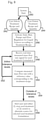
- FIG. 2 shows a flow chart of an embodiment of Automated Switching of Chemical Sources.
- FIG. 3 shows a flow chart of an embodiment of Detecting Product Change by Change in Density.
- FIG. 4 shows a flow chart of an embodiment of Storing Agrochemical Data to Database.
- FIG. 5 shows a flow chart of an embodiment of Changing Seed Treatment Application Based on Temperature of Liquid Agrochemical.
- FIG. 6 shows a flow chart of a method for adjusting the flow rates based on the measured mass flow signal.
- FIG. 7 shows a flow chart of a method for alerting the user to verify appropriate seed treatment formulation and stop treatment based on density range being out of tolerance.
- FIG. 8 shows a flow chart of a method for stopping seed treatment or switching to an alternate source for selected seed treatment formulation upon a measured flow rate being out of tolerance.
- FIG. 9 an embodiment of a seed treatment applicator system showing multiple liquid sources and a pair of modular control sticks, each control stick containing the respective mass flow meters and flow regulators.
- FIG. 10 is an enlarged front view of the modular control sticks of the embodiment of FIG. 9 .
- FIG. 11 is an enlarged side view of the modular control sticks of the embodiment of FIG. 9 .
- this seed treatment control system for liquid agrochemicals overcomes numerous problems, such as required user calibrations, external interference with scale systems, liquid source changes without interruption, and broader equipment size and placement restrictions.
- a mass flow meter 24 is in fluid communication with each liquid source 2 , 4 .
- the mass flow meter 24 is fluidly connected downstream of the liquid pump 20 through fluid connection 22 .
- the mass flow meter 24 generates an electric signal relative to the mass of the liquid flow.
- the liquid source 4 is fluidly connected to the multi-port valve 16 by a fluid connection 14 , such as a tube.
- a pump 20 is in fluid communication with the liquid source via fluid connection 18 .
- the pump is preferably an air operated, double diaphragm pump.
- the double diaphragm air pump may be advantageous because it can hold a constant pressure on the fluid line without compromising the pump 20 .
- the pump 20 slows down until the liquid pressure drops.
- the pump 20 remains energized and the fluid remains pressurized.
- the pump 20 can maintain a potential liquid flow rate without negatively affecting pump 20 .
- the pump 20 must have sufficient pressure capabilities to satisfy the plumbing requirements of the system.
- the pressure requirements are based on the plumbing arrangement.
- the pressure drops through tubing, check valves, and across the static mixer 54 .
- a flow meter is in fluid communication with each liquid source.
- the flow meter could be a volumetric flow meter or a mass flow meter 24 .
- An example of a volumetric flow meter is a magnetic flow meter. Volumetric flow meters must be calibrated for each product that is put through it.
- the flow meter provides an individual flow rate signal corresponding to the flow rate for each product.
- the control system is configured to receive each individual flow rate signal.
- the flow meter generates a flow rate signal for each liquid source product.
- the flow meter generates an analog electric signal corresponding to the flow rate for each product.
- the flow meter is in electric communication with the control system.
- the flow meter is a mass flow meter 24 , such as a Corilios mass flow meter.
- the mass flow meter 24 would be advantageous to eliminate the calibration step for the volumetric flow meter.
- the mass flow meter 24 provides electronic signals corresponding to the real-time mass flow rate, density, and temperature of the fluid using direct inline measurement.
- the mass flow meter 24 is configured to calculate a volumetric flow rate and a totalized fluid ounces per operation cycle.
- a proportional-integral-derivative (“PID”) control loop determines whether the measured mass rate deviates from the programmed desired mass rate reference value. The operator or programmer can affect the compensation value to tune flow rate adjustments. Tuning of the flow rate adjustment may depend on the viscosity of the fluid and the desired mass rate.
- the meter used to generate the flow signal is a mass meter—such as a scale with a load cell—that receives the fluid source container.
- the mass meter generates a mass flow signal.
- the control system is configured to calculate a flow rate based on a loss-in-weight calculation of the change in mass signal over a time interval.
- a liquid flow regulator 28 is in fluid communication with the liquid source downstream of the mass flow meter 24 and connected to the mass flow meter by a fluid connection 26 .
- the liquid flow regulator 28 provides control over the flow rate of the product.
- the control system sends an analog control signal that is received by the liquid flow regulator 28 .
- the liquid flow regulator 28 responds proportionately.
- the liquid flow regulator 28 can comprise an electro-pneumatic valve, which converts analog electric signal to pneumatic control over the valve, thereby affecting the flow rate.
- the liquid flow regulator 28 is positioned downstream from flow meter because the regulator 28 causes the flow of the liquid to be turbulent.
- the liquid flow regulator 28 is comprised of Teflon to increase compatibility with a variety of products.
- liquid sources can be fluidly connected with a pump 20 , mass flow meter 24 , and fluid regulator 28 .
- the first seed treatment fluid source #1 and the first seed treatment fluid source #2 are connected to a single pump 20 , mass flow meter 24 , and liquid flow regulator 28 through a three-way valve.
- the agricultural seed treatment control system for liquid agrochemicals can be described as having respective fluid handling assemblies for each seed treatment fluid.
- Each fluid handling assembly comprises a static-rate pump for each fluid source.
- Each fluid handling assembly has at least one inlet fluid connection for connecting to a respective fluid source and an outlet fluid connection for directing a first pressurized fluid.
- Each fluid handling assembly comprises a meter that generates a fluid signal in relation to the amount of the fluid flowing from the fluid source.
- Each fluid handling assembly also comprises a proportional valve fluidly connected downstream of the meter, the proportional valve biased in a closed position.
- Each proportional valve receives the respective control signal; and each proportional valve opens in response to the respective control signal whereby a desired flow rate of each fluid is continuously delivered to a downstream mixing assembly.
- a liquid manifold 32 is in fluid communication with each fluid handling assembly.
- the flow regulator 28 is shown connected to a first port 34 of the liquid manifold 32 through fluid connection 30 .
- the liquid manifold 32 is a chamber for receiving multiple liquid source connections.
- the liquid manifold 32 could be an aluminum manifold 32 with multiple ports 34 , 36 , 38 , 40 , 42 .
- a third liquid source 44 is directly connected via fluid connection 46 to port 40 on the manifold.
- a forth liquid source 48 is connected via fluid connection 50 to port 42 .
- the function of the liquid manifold 32 is to combine the multiple fluid sources into a single output.
- the liquid manifold 32 has a plurality of inlet ports to allow connections from a plurality of liquid sources.
- the liquid manifold 32 discharges the single output into the inlet for the liquid atomizer within the seed treatment chamber 66 .
- the liquid manifold 32 is oriented vertically, with output flow out the top.
- the higher rate sources are connected into bottom, lower rate product in through the top.
- the higher rate liquid connections are located furthest from the discharge point and the lower rate liquid connections are located closer to the discharge point. This allows the higher rate liquid product flow to carry the lower rate liquid through the liquid manifold 32 .
- a one-way check valve is in fluid communication with each port of the manifold 32 .
- the check valves prevent liquid back-flow. This allows the system to avoid cross contamination from one recipe to another.
- the check valves are self-sealing, non-reactant and not dependent on gravity, mounting position, or reverse flow.
- a mixing assembly having a static mixer 54 is in fluid communication with the liquid manifold 32 via fluid connection 52 .
- the static mixer 54 can be an inline static mixer, which creates a mixing action as the liquid moves through the static mixer 54 .
- the static mixer 54 incorporates a turbulence-inducing mixing element in the liquid flow path. These turbulence-inducing mixing elements can have specific shapes and sizes—such as a blade, helix, or wafer—to efficiently cause the liquids to blend.
- the specific design of the static mixer 54 would depend on the characteristics of the liquids to be blended in a specific application.
- the static mixer 54 is oriented vertically. Liquid flows up through the static mixer 54 .
- the vertical orientation is advantageous because the liquid flow can vary. It is important that the liquid does not merely trickle through the static mixer 54 .
- the static mixer 54 is fluidly connected with a seed treatment applicator 60 via fluid connection 56 .
- the seed treatment applicator atomizes the seed treatment fluid upon a seed flow according to a recipe.
- the seed treatment liquids are delivered into a delivery shuttle.
- the delivery shuttle is a liquid container that receives the blended liquid.
- the delivery shuttle is a one-time use receptacle.
- the delivery shuttle can be sized as appropriate for the quantity of liquid desired by the customer.
- the delivery shuttle is a 260-gallon container.
- the delivery shuttle can be a standard 5-gallon bucket.
- the delivery shuttle is positioned on a scale for measuring the mass of blended liquid delivered into the delivery shuttle.
- An air purge valve may connected to the liquid manifold 32 .
- the air purge valve can be opened to provide a flow of compressed air from a compressed air source to purge residual fluid at the end of the blending delivery cycle. Substantially all liquid product needs to be removed from the manifold 32 and downstream of the manifold 32 .
- the air purge forces liquid through liquid connections into the shuttle or through a discharge fluid connection. This provides the customer with a complete delivery of product and also provides an initial cleaning of the blended product.
- the air purge provides a medium that naturally separates from the blended liquid product.
- the control system can be programmed to automatically trigger the air purge at the end of blending delivery cycle.
- a solvent purge valve is also connected to the liquid manifold 32 .
- the solvent purge valve can be opened to provide a flow of pressurized solvent from a pressurized solvent source to purge residual fluid at the end of the blending delivery cycle and after the air purge.
- the solvent purge flushes residual fluid from the system. Generally, this waste solvent mixture must be collected and disposed of.
- the air purge step minimizes the amount of solvent necessary to clear the system of residual liquid.
- the solvent used is water.
- the control system can be programmed to automatically trigger the solvent purge at the end of blending delivery cycle and after the air purge.
- a pneumatic source may be connected to the air-in port 80 of the control stick 70 to operated the flow regulator 28 .
- the pneumatic source may also be connected to each of the pumps, valves, and regulating proportional valves.
- the control system receives each fluid signal each mass flow signal.
- the control system is in electric communication with the various air valves, liquid flow regulators (proportional valves), and each of the static-rate fluid pumps.
- the control system generates a control signal for each proportional valve based on the respective fluid signal and a treatment recipe.
- Each proportional flow regulating valve receives the respective control signal opens in response to the respective control signal whereby a desired flow rate of each fluid is continuously delivered to a downstream mixing assembly.
- the modular system is designed to accommodate multiple liquid sources, in some embodiments of the modular system there are between 2 to 20 liquid sources. Additional capacity can be added to the system by adding additional control sticks 70 , 72 . Modular control sticks 70 , 72 may also provide the advantage of continued operation in case of equipment failure. For example, if a component within the control stick would fail during the seed treatment season, a replacement control stick could be quickly and easily swapped for the faulty control stick.
- the modularity of the control sticks also provide easy opportunity for the User to add capacity to their seed treatment system. For example, if a User desires to add additional fluid sources, then an additional modular control stick can be added to the seed treatment system and connected in series alongside the other modular control sticks.
- certain embodiments may incorporate a density meter such as a Berthold Technologies SmartSeries LB 414 Gamma Densitometer.
- the Gamma Densitometer utilizes a radiometric detector to generate respective signals relative to the liquid's density, concentration and solids content measurements.
- the seed treatment applicator can comprise one or more modular control sticks 70 , 72 .
- the first liquid source 2 and second liquid source 3 are fluidly connected to the first liquid pump 20 through a multi-port valve 16 .
- Fluid connection 18 fluidly connects the output of the first liquid pump 20 with a fluid-in port 87 on the first modular control stick 70 .
- a third liquid source 44 is fluidly connected to a second liquid pump 21 directly.
- the second liquid pump 21 is fluidly connected to a second modular control stick 72 .
- the modular control sticks 70 , 72 are swappable units for controlling the flow of the liquid from the respective liquid source and for generating signals corresponding to the mass flow rates, density, and temperature of the liquid seed treatment.
- the modular control sticks are shown in FIG. 9 as mounted to the treatment chamber 66 .
- the modular control sticks 70 , 72 measure the liquid seed treatment at a point in the fluid system physically near the point of use.
- Use of the modular control sticks 70 , 72 allows the seed treatment applicator to utilize static rate pumps that maintain a constant positive pressure over long distances.
- the fluid sources 1 , 2 , 4 and the pumps 20 , 21 may be located up to 20′ from the modular control sticks 70 , 72 .
- the fluid sources 1 , 2 , 4 and the pumps 20 , 21 may be located up to 100′ from the modular control sticks 70 , 72 .
- Another advantage to moving the fluid sources 1 , 2 , 4 at a greater distance from the modular control sticks 70 , 72 is to facilitate the replacement or filling of the liquid sources in a more readily accessible portion of the seed treatment facility.
- the fluid sources 1 , 2 , 4 may also be kept in a controlled environment apart from the other equipment.
- the modular control sticks 70 , 72 comprise a frame 99 upon which a variety of ports are mounted on the front surface 98 .
- the front surface 98 comprises an air-in port 80 , a power in port 82 , an Ethernet out port 83 , an Ethernet in port 85 , a fluid out port 84 , a fluid in port 87 , and an exhaust port 86 .
- the fluid out port 84 is fluidly connected to the atomizer inlet port 64 .
- a power button 81 is also mounted on the front surface 98 .
- An elongated frame portion 97 is perpendicular to the front portion 98 of the frame 99 .
- the mass flow meter 24 , flow meter transmitter 92 , flow regulator 28 , flow regulator controller 88 , and central processing unit (“CPU”) box 90 are mounted to the elongated frame portion 97 .
- a first internal fluid connection 23 connects the fluid in port 87 to the mass flow meter 24 downstream of the fluid in port.
- a second internal fluid connection 25 connects the mass flow meter 24 to the flow regulator 28 downstream of the mass flow meter.
- the flow regulator 28 is fluidly connected to the fluid out port 84 through a third internal fluid connection 29 .
- the flow meter transmitter 92 is electrically coupled to the flow meter 24 to communicate flow value data to the monitoring system, such as the CPU box 90 and the main applicator control system with user interface.
- the fluid source of the liquid seed treatment can be automatically changed.
- the controller accesses a seed treatment recipe comprising a first agrochemical, as shown in Step 102 .
- the controller accesses a tolerance level for the first flow signal related to changes in flow rate, as shown in Step 104 .
- the user initiates seed treatment according to the seed treatment recipe, as shown in Step 106 .
- the controller generates a first source select signal and a first flow signal from a mass flow meter, as shown in Step 108 .
- the controller monitors the first measured mass flow signal, as shown in Step 110 .
- the flow regulator receives the first flow signal, as shown in Step 120 .
- the flow regulator opens in response to the first flow signal, as shown in Step 122 .
- the multi-port valve receives a first source select signal, as shown in Step 126 .
- the multi-port valve opens the valve to select the first agrochemical source 128 .
- the mass flow meter then generates a first measured mass flow signal corresponding to the flow rate of the first agrochemical flow, as shown in Step 136 .
- the controller monitors the first measured mass flow signal.
- the controller compares the first measured mass flow signal with the desired rate according to the seed treatment recipe and the tolerance level, as shown in Step 112 .
- the controller generates a source change signal if the measured flow signal deviates from the first flow signal, as shown in Step 114 .
- the multi-port valve 16 receives the source change signal, as shown in Step 130 , and then closes the valve for the first agrochemical source, as shown in Step 132 , and opens the valve for the second agrochemical source, as shown in Step 134 .
- the system generates an alert, such as a user error message, to notify the user to check and replace the first fluid source, as shown in Step 116 .
- the user error message can be displayed upon the user interface of the controller.
- the multi-port valve 16 can be manually operated or an electro-pneumatic valve.
- an agrochemical product change can be automatically detected by a change in in the direct inline measurement of the density of the liquid seed treatment.
- the controller accesses a seed treatment recipe comprising a first agrochemical, as shown in Step 150 .
- the controller accesses a database having a list of agrochemicals and corresponding density ranges, as shown in Step 152 .
- the user can manually input the density range of the selected agrochemical or the user may automatically input the density range into the controller by scanning a bottle or a product information sheet.
- the user initiates seed treatment through the controller, as shown in Step 154 .
- the controller generates a first source select signal and a first flow signal, as shown in Step 156 .
- the flow regulator receives the first flow signal, as shown in Step 166 .
- the flow regulator proportionally opens in response to the first flow signal, as shown in Step 168 .
- the multi-port valve if present, receives the first source select signal, as shown in Step 176 , and opens the valve to select the first agrochemical source, as shown in Step 178 .
- the mass flow meter generates a first density signal corresponding to the direct inline measurement of the density of the first agrochemical, as shown in Step 180 .
- the controller monitors the first density signal, as shown in Step 158 .
- the controller generates a stop flow signal if the density signal exceeds the density range for the selected agrochemical, as shown in Step 160 .
- the flow regulator receives the stop flow signal, as shown in Step 170 , and closes the flow regulator to stop the flow of the first liquid seed treatment, as shown in Step 172 .
- the controller may then generate an alert to notify the user to confirm the first fluid source contains the proper chemical composition, as shown in Step 162 .
- agrochemical data can be stored to a database manually or directly.
- a first supply tank of a first agrochemical is positioned near a first pump station, as shown in Step 200 .
- the first supply tank is fluidly connected to a first port of a multi-port valve, as shown in Step 202 .
- Agrochemical data is transferred from a first supply tank to the control system, as shown in Step 204 .
- the agrochemical data may include: chemical name, batch number, density, or safety and handling information.
- the user enters the pump station identification and multi-port valve number corresponding to the fluid connection 206 .
- a second supply tank of the first agrochemical is positioned near the first pump station, as shown in Step 212 .
- the second supply tank is fluidly connected to a second port of the multi-port valve, as shown in Step 214 .
- Agrochemical data is transferred from a second supply tank to the control system, as shown in Step 216 .
- the agrochemical data may include: chemical name, batch number, density, or safety and handling information.
- the user enters the pump station identification and multi-port valve number corresponding to the fluid connection 218 .
- the system stores data to a database having a list of agrochemicals and corresponding density ranges, as shown in Step 208 .
- parameters of the seed treatment application can be changed in real time based on inline direct measurement of the liquid agrochemical.
- the controller accesses a seed treatment recipe comprising a first agrochemical, as shown in Step 230 .
- the User initiates seed treatment through the controller, as shown in Step 232 .
- the controller generates a first flow signal, as shown in Step 234 .
- the flow regulator receives the first flow signal, as shown in Step 248 , and the flow regulator opens in response to the first flow signal, as shown in Step 250 .
- the controller may generate a first source select signal, as shown in Step 236 .
- the multi-port valve receives a first source select signal, as shown in Step 252 , and opens the valve for the first agrochemical, as shown in Step 254 .
- the Mass Flow Meter generates a first flow rate signal corresponding to the flow rate of the first agrochemical, as shown in Step 256 .
- the controller monitors the first flow rate signal, as shown in Step 238 .
- the mass flow meter also generates a first temperature signal corresponding to the temperature of the first agrochemical, as shown in Step 258 .
- the controller monitors the first temperature signal, as shown in Step 240 .
- the controller calculates the adjustments based on the first temperature signal to change one of more of the following treatment parameters: seed flow rate, drying drum retention time, drying drum rotation speed, conditioned air flow rate, conditioned air temperature, conditioned air humidity, or rotation speed of the atomizing disk, as shown in Step 242 . Additionally, the controller may regulate the admission of supplemental water into the manifold 32 from a separate water source based on the direct inline measured temperature of the first agrochemical. The controller records the first temperature signal with the operational data of the seed treatment application, as shown in Step 244 .
- the seed flow rates can be adjusted based on the measured mass flow signal of a liquid seed treatment formulation.
- the User selects the treatment recipe and quantity, as shown in Step 304 .
- the User may enter the treatment recipe and quantity, as shown in Step 306 .
- the static flow rate pumps are activated for appropriate fluid sources according to the treatment recipe, as shown in Step 308 .
- the flow regulators are proportionately opened for appropriate fluid sources according to the treatment recipe.
- the mass flow meter generates a real-time measured mass flow rate, which is received by the controller, as shown in Step 310 .
- the seed flow rate is adjusted based on a measured mass flow rate of the seed treatment formulation, as shown in Step 312 .
- the user can be alerted to verify appropriate seed treatment formulation and stop treatment based on a measured density range being out of tolerance.
- the User selects the treatment recipe and quantity, as shown in Step 322 .
- the User may enter the treatment recipe and quantity, as shown in Step 324 .
- the static-rate pump is activated for appropriate liquid sources according to the treatment recipe, as shown in Step 326 .
- the flow regulators are proportionately opened for appropriate fluid sources according to the treatment recipe.
- the mass flow meter generates real-time measured density signal for the seed treatment formulation, as shown in Step 328 .
- the controller compares the measured seed treatment formulation density with the reference density value for the seed treatment formulation, as shown in Step 330 .
- Step 332 If the comparison is within tolerance levels, then the system continues to operate and receive the measured density signal, as shown in Step 332 . If the comparison is outside of tolerance levels 334 , then the system alerts the User to verify appropriate seed treatment formulation and stop seed treatment, as shown in Step 336 .
- the seed treatment system can stop treating seed or switching to an alternate source for selected seed treatment formulation upon a measured flow rate being out of tolerance.
- the User selects the treatment recipe and quantity, as shown in Step 342 .
- the User may enter the treatment recipe and quantity, as shown in Step 344 .
- the static-rate pumps are activated for appropriate fluid sources according to the treatment recipe, as shown in Step 346 .
- the flow regulators are proportionately opened for appropriate fluid sources according to the treatment recipe.
- the mass flow meter generates a real-time measured mass flow rate, which is received by the controller, as shown in Step 348 .
- the controller compares the measured mass flow rate with a reference mass flow rate value corresponding to the selected treatment recipe, as shown in Step 350 . If the comparison is within tolerance levels, then the system continues to operate and receive the measured density signal, as shown in Step 352 . If the comparison is outside of tolerance levels 354 , then the system may stop treatment and alert the User to switch to an alternate source for the selected seed treatment formulation, as shown in Step 356 . If the system is configured with an electro-pneumatic multi-port valve, then the system generates a fluid source change signal to automatically switch from a first fluid source having the desired liquid seed treatment to a second fluid source having the desired liquid seed treatment.
- One advantage of the current disclosure is that the system can compensate for a change in density between a first liquid source containing a first treatment mixture of a liquid seed treatment having a first density and a second liquid source containing a second treatment mixture of the liquid seed treatment having a second density, where the first density is different than the second density.
- Existing systems would have to be recalibrated to compensate for the difference in density. This may be particularly advantageous when Users make their own seed treatment mixtures from solids or concentrate.
- the first liquid source 2 is disposed upon a first scale 8 and the second liquid source 4 is disposed upon a second scale 10 .
- the first scale 8 and second scale 10 are operably connected to the controller to generate a weight signal corresponding to the real time weight of the respective liquid source and its contents.
- the weight signal can be converted to a loss-in-weight calculation to verify the mass flow meter.
- a first set of liquid sources may be metered using the mass flow meter and a second set of liquid sources may be metered using loss-in-weight calculation.
Landscapes
- Life Sciences & Earth Sciences (AREA)
- Soil Sciences (AREA)
- Environmental Sciences (AREA)
- Accessories For Mixers (AREA)
Abstract
Description
- a) Capable of legal-for-trade transaction for liquid dispensed;
- b) Receives real-time density to verify product being applied;
- c) Unlike rate-of-change or scale system, there will be no external influence—such as wind, rain, hail, debris, or vibration from nearby equipment—that could affect the application rate or amount;
- d) Ability to add or change out liquid on the fly—the user cannot add liquid to a rate-of-change system with a scale without compromising the application rate calculation;
- e) Real-time density measurement removes all calibration and density calculation processes, removing an error-prone step essential for the application rate calculation in other application methods.
Claims (18)
Priority Applications (1)
| Application Number | Priority Date | Filing Date | Title |
|---|---|---|---|
| US16/110,944 US11252855B2 (en) | 2017-08-23 | 2018-08-23 | Agricultural seed treatment control system for liquid agrochemicals |
Applications Claiming Priority (2)
| Application Number | Priority Date | Filing Date | Title |
|---|---|---|---|
| US201762549006P | 2017-08-23 | 2017-08-23 | |
| US16/110,944 US11252855B2 (en) | 2017-08-23 | 2018-08-23 | Agricultural seed treatment control system for liquid agrochemicals |
Publications (2)
| Publication Number | Publication Date |
|---|---|
| US20190059205A1 US20190059205A1 (en) | 2019-02-28 |
| US11252855B2 true US11252855B2 (en) | 2022-02-22 |
Family
ID=65433935
Family Applications (1)
| Application Number | Title | Priority Date | Filing Date |
|---|---|---|---|
| US16/110,944 Active 2039-10-31 US11252855B2 (en) | 2017-08-23 | 2018-08-23 | Agricultural seed treatment control system for liquid agrochemicals |
Country Status (1)
| Country | Link |
|---|---|
| US (1) | US11252855B2 (en) |
Cited By (1)
| Publication number | Priority date | Publication date | Assignee | Title |
|---|---|---|---|---|
| WO2024015230A1 (en) * | 2022-07-13 | 2024-01-18 | Pivot Bio, Inc. | Seed treatment systems, methods, and agricultural compositions |
Families Citing this family (2)
| Publication number | Priority date | Publication date | Assignee | Title |
|---|---|---|---|---|
| US11968919B2 (en) | 2021-02-26 | 2024-04-30 | D. Landon Smith | Seed treater |
| US12433188B2 (en) | 2023-01-16 | 2025-10-07 | KSi Conveyor, Inc. | Seed metering and discharge system with adjustable gate control |
Citations (14)
| Publication number | Priority date | Publication date | Assignee | Title |
|---|---|---|---|---|
| US5537914A (en) * | 1989-10-04 | 1996-07-23 | Micro-Blend, Inc. | Beverage blending and proportioning |
| US6186193B1 (en) * | 1996-11-15 | 2001-02-13 | Oden Corporation | Continuous liquid stream digital blending system |
| US20040057334A1 (en) | 2001-07-31 | 2004-03-25 | Wilmer Jeffrey Alexander | Method and apparatus for blending process materials |
| US20060255060A1 (en) * | 2005-05-12 | 2006-11-16 | Mark Miller | Method and apparatus for dispensing liquid at a desired flow rate |
| WO2008016368A1 (en) | 2006-08-01 | 2008-02-07 | Syngenta Participations Ag | Apparatus and method for treating seeds |
| US20110027479A1 (en) | 2009-08-03 | 2011-02-03 | Greg Reineccius | Seed Treatment Apparatus |
| US20120189762A1 (en) * | 2010-12-08 | 2012-07-26 | Bayer Cropscience Lp | Seed treatment facilities, methods and apparatus |
| US20130292407A1 (en) | 2007-09-06 | 2013-11-07 | Deka Products Limited Partnership | Product Dispensing System |
| US8644993B1 (en) | 2013-03-14 | 2014-02-04 | Usc, L.L.C. | Method of controlling the flow rate of the liquid by controlling operation of the pump |
| US9510584B2 (en) | 2007-05-11 | 2016-12-06 | Syngenta Crop Protection Llc | Systems, components and methods for delivering liquid substances |
| US9658624B2 (en) | 2010-11-09 | 2017-05-23 | Agrilead, Inc. | Seed index system for treating agricultural seeds |
| US20170189868A1 (en) | 2016-01-06 | 2017-07-06 | KSi Conveyor, Inc. | Automated Liquid Blending System |
| US20170274331A1 (en) | 2016-03-23 | 2017-09-28 | KSi Conveyor, Inc. | Horizontal Fluent Material Dispenser |
| US20180352720A1 (en) * | 2015-11-24 | 2018-12-13 | Rhodia Operations | Seed treatment method |
-
2018
- 2018-08-23 US US16/110,944 patent/US11252855B2/en active Active
Patent Citations (15)
| Publication number | Priority date | Publication date | Assignee | Title |
|---|---|---|---|---|
| US5537914A (en) * | 1989-10-04 | 1996-07-23 | Micro-Blend, Inc. | Beverage blending and proportioning |
| US6186193B1 (en) * | 1996-11-15 | 2001-02-13 | Oden Corporation | Continuous liquid stream digital blending system |
| US20040057334A1 (en) | 2001-07-31 | 2004-03-25 | Wilmer Jeffrey Alexander | Method and apparatus for blending process materials |
| US20060255060A1 (en) * | 2005-05-12 | 2006-11-16 | Mark Miller | Method and apparatus for dispensing liquid at a desired flow rate |
| WO2008016368A1 (en) | 2006-08-01 | 2008-02-07 | Syngenta Participations Ag | Apparatus and method for treating seeds |
| US9510584B2 (en) | 2007-05-11 | 2016-12-06 | Syngenta Crop Protection Llc | Systems, components and methods for delivering liquid substances |
| US20130292407A1 (en) | 2007-09-06 | 2013-11-07 | Deka Products Limited Partnership | Product Dispensing System |
| US20110027479A1 (en) | 2009-08-03 | 2011-02-03 | Greg Reineccius | Seed Treatment Apparatus |
| US9658624B2 (en) | 2010-11-09 | 2017-05-23 | Agrilead, Inc. | Seed index system for treating agricultural seeds |
| US20120189762A1 (en) * | 2010-12-08 | 2012-07-26 | Bayer Cropscience Lp | Seed treatment facilities, methods and apparatus |
| US20170215331A1 (en) | 2010-12-08 | 2017-08-03 | Bayer Cropscience Lp | Seed treatment facilities, methods, and apparatus |
| US8644993B1 (en) | 2013-03-14 | 2014-02-04 | Usc, L.L.C. | Method of controlling the flow rate of the liquid by controlling operation of the pump |
| US20180352720A1 (en) * | 2015-11-24 | 2018-12-13 | Rhodia Operations | Seed treatment method |
| US20170189868A1 (en) | 2016-01-06 | 2017-07-06 | KSi Conveyor, Inc. | Automated Liquid Blending System |
| US20170274331A1 (en) | 2016-03-23 | 2017-09-28 | KSi Conveyor, Inc. | Horizontal Fluent Material Dispenser |
Non-Patent Citations (2)
| Title |
|---|
| ASCO, Air and Water Solenoid Valves, 3/2 Series 8316, Feb. 1, 2001, pp. 49-52. |
| USC, LPX Mass Flow Meter Rev B Manual Pumpstand, Operators Manual, May 7, 2015, 28 pages. |
Cited By (1)
| Publication number | Priority date | Publication date | Assignee | Title |
|---|---|---|---|---|
| WO2024015230A1 (en) * | 2022-07-13 | 2024-01-18 | Pivot Bio, Inc. | Seed treatment systems, methods, and agricultural compositions |
Also Published As
| Publication number | Publication date |
|---|---|
| US20190059205A1 (en) | 2019-02-28 |
Similar Documents
| Publication | Publication Date | Title |
|---|---|---|
| US20150306555A1 (en) | Methods and apparatus for mixing dairy animal treatment chemicals | |
| US8744633B2 (en) | Input dispenser and recorder | |
| US20170189868A1 (en) | Automated Liquid Blending System | |
| AU618043B2 (en) | Postmix juice dispensing system | |
| JP7051802B2 (en) | Atomizer with replaceable cartridge | |
| US20210007267A1 (en) | Seed treatment facilities, methods and apparatus | |
| US6253959B1 (en) | Measuring and dispensing system for solid dry flowable materials | |
| US11252855B2 (en) | Agricultural seed treatment control system for liquid agrochemicals | |
| EP1378293A1 (en) | Method and system for the direct injection and dosing of active materials intended for phytosanitary product applicators | |
| BR112013013940B1 (en) | AUTOMATED SEED TREATMENT SYSTEM ADAPTED FOR OPERATION ON THE SITE IN A RETAIL DISTRIBUTOR | |
| PL196346B1 (en) | Precision dispenser for liquids | |
| ES2887379T3 (en) | Production system to elaborate formulations | |
| US8504211B2 (en) | Input dispenser and recorder | |
| US20190155244A1 (en) | Retail point seed treatment systems and methods | |
| WO1997002898A1 (en) | Comprehensive product delivery system | |
| US20060255060A1 (en) | Method and apparatus for dispensing liquid at a desired flow rate | |
| US20220400601A1 (en) | Agricultural Seed Conveyor with Low Pressure Liquid Treatment System | |
| CN105492112A (en) | Agrochemicals pre-dilution unit | |
| BR102018069017A2 (en) | FULL AUTOMATED ELECTRONIC CONTROL AGROTOXIC MIXING SYSTEM | |
| EP0003184A1 (en) | Apparatus for injecting metered quantities of fluid into a flowing stream of liquid | |
| CN207213649U (en) | Solution feeding system | |
| US20260002597A1 (en) | Mixing device | |
| US20210291130A1 (en) | Fluid Injection System | |
| BR112013013937B1 (en) | seed treatment apparatus, methods and facilities | |
| AU8322598A (en) | Mixing and dispensing system |
Legal Events
| Date | Code | Title | Description |
|---|---|---|---|
| FEPP | Fee payment procedure |
Free format text: ENTITY STATUS SET TO UNDISCOUNTED (ORIGINAL EVENT CODE: BIG.); ENTITY STATUS OF PATENT OWNER: SMALL ENTITY |
|
| AS | Assignment |
Owner name: KSI CONVEYOR, INC., KANSAS Free format text: ASSIGNMENT OF ASSIGNORS INTEREST;ASSIGNORS:MEYER, DOMINIC E;KAEB, JASON P;REEL/FRAME:046788/0441 Effective date: 20180831 |
|
| FEPP | Fee payment procedure |
Free format text: ENTITY STATUS SET TO SMALL (ORIGINAL EVENT CODE: SMAL); ENTITY STATUS OF PATENT OWNER: SMALL ENTITY |
|
| STPP | Information on status: patent application and granting procedure in general |
Free format text: DOCKETED NEW CASE - READY FOR EXAMINATION |
|
| STPP | Information on status: patent application and granting procedure in general |
Free format text: NON FINAL ACTION MAILED |
|
| STPP | Information on status: patent application and granting procedure in general |
Free format text: RESPONSE TO NON-FINAL OFFICE ACTION ENTERED AND FORWARDED TO EXAMINER |
|
| STPP | Information on status: patent application and granting procedure in general |
Free format text: FINAL REJECTION MAILED |
|
| STPP | Information on status: patent application and granting procedure in general |
Free format text: RESPONSE AFTER FINAL ACTION FORWARDED TO EXAMINER |
|
| STPP | Information on status: patent application and granting procedure in general |
Free format text: NOTICE OF ALLOWANCE MAILED -- APPLICATION RECEIVED IN OFFICE OF PUBLICATIONS |
|
| STCF | Information on status: patent grant |
Free format text: PATENTED CASE |
|
| MAFP | Maintenance fee payment |
Free format text: PAYMENT OF MAINTENANCE FEE, 4TH YR, SMALL ENTITY (ORIGINAL EVENT CODE: M2551); ENTITY STATUS OF PATENT OWNER: SMALL ENTITY Year of fee payment: 4 |