US11247526B2 - Roll stabilizer and use of a roll stabilizer in a motor vehicle - Google Patents
Roll stabilizer and use of a roll stabilizer in a motor vehicle Download PDFInfo
- Publication number
- US11247526B2 US11247526B2 US16/608,250 US201816608250A US11247526B2 US 11247526 B2 US11247526 B2 US 11247526B2 US 201816608250 A US201816608250 A US 201816608250A US 11247526 B2 US11247526 B2 US 11247526B2
- Authority
- US
- United States
- Prior art keywords
- housing
- transmission
- electric motor
- stabilizer
- roll stabilizer
- Prior art date
- Legal status (The legal status is an assumption and is not a legal conclusion. Google has not performed a legal analysis and makes no representation as to the accuracy of the status listed.)
- Expired - Fee Related, expires
Links
Images


Classifications
-
- B—PERFORMING OPERATIONS; TRANSPORTING
- B60—VEHICLES IN GENERAL
- B60G—VEHICLE SUSPENSION ARRANGEMENTS
- B60G21/00—Interconnection systems for two or more resiliently-suspended wheels, e.g. for stabilising a vehicle body with respect to acceleration, deceleration or centrifugal forces
- B60G21/02—Interconnection systems for two or more resiliently-suspended wheels, e.g. for stabilising a vehicle body with respect to acceleration, deceleration or centrifugal forces permanently interconnected
- B60G21/04—Interconnection systems for two or more resiliently-suspended wheels, e.g. for stabilising a vehicle body with respect to acceleration, deceleration or centrifugal forces permanently interconnected mechanically
- B60G21/05—Interconnection systems for two or more resiliently-suspended wheels, e.g. for stabilising a vehicle body with respect to acceleration, deceleration or centrifugal forces permanently interconnected mechanically between wheels on the same axle but on different sides of the vehicle, i.e. the left and right wheel suspensions being interconnected
- B60G21/055—Stabiliser bars
- B60G21/0551—Mounting means therefor
- B60G21/0553—Mounting means therefor adjustable
- B60G21/0555—Mounting means therefor adjustable including an actuator inducing vehicle roll
-
- B—PERFORMING OPERATIONS; TRANSPORTING
- B60—VEHICLES IN GENERAL
- B60G—VEHICLE SUSPENSION ARRANGEMENTS
- B60G21/00—Interconnection systems for two or more resiliently-suspended wheels, e.g. for stabilising a vehicle body with respect to acceleration, deceleration or centrifugal forces
- B60G21/02—Interconnection systems for two or more resiliently-suspended wheels, e.g. for stabilising a vehicle body with respect to acceleration, deceleration or centrifugal forces permanently interconnected
- B60G21/04—Interconnection systems for two or more resiliently-suspended wheels, e.g. for stabilising a vehicle body with respect to acceleration, deceleration or centrifugal forces permanently interconnected mechanically
- B60G21/05—Interconnection systems for two or more resiliently-suspended wheels, e.g. for stabilising a vehicle body with respect to acceleration, deceleration or centrifugal forces permanently interconnected mechanically between wheels on the same axle but on different sides of the vehicle, i.e. the left and right wheel suspensions being interconnected
- B60G21/055—Stabiliser bars
-
- B—PERFORMING OPERATIONS; TRANSPORTING
- B60—VEHICLES IN GENERAL
- B60G—VEHICLE SUSPENSION ARRANGEMENTS
- B60G21/00—Interconnection systems for two or more resiliently-suspended wheels, e.g. for stabilising a vehicle body with respect to acceleration, deceleration or centrifugal forces
- B60G21/10—Interconnection systems for two or more resiliently-suspended wheels, e.g. for stabilising a vehicle body with respect to acceleration, deceleration or centrifugal forces not permanently interconnected, e.g. operative only on acceleration, only on deceleration or only at off-straight position of steering
-
- H—ELECTRICITY
- H02—GENERATION; CONVERSION OR DISTRIBUTION OF ELECTRIC POWER
- H02K—DYNAMO-ELECTRIC MACHINES
- H02K5/00—Casings; Enclosures; Supports
- H02K5/24—Casings; Enclosures; Supports specially adapted for suppression or reduction of noise or vibrations
-
- H—ELECTRICITY
- H02—GENERATION; CONVERSION OR DISTRIBUTION OF ELECTRIC POWER
- H02K—DYNAMO-ELECTRIC MACHINES
- H02K7/00—Arrangements for handling mechanical energy structurally associated with dynamo-electric machines, e.g. structural association with mechanical driving motors or auxiliary dynamo-electric machines
- H02K7/10—Structural association with clutches, brakes, gears, pulleys or mechanical starters
- H02K7/116—Structural association with clutches, brakes, gears, pulleys or mechanical starters with gears
-
- B—PERFORMING OPERATIONS; TRANSPORTING
- B60—VEHICLES IN GENERAL
- B60G—VEHICLE SUSPENSION ARRANGEMENTS
- B60G2202/00—Indexing codes relating to the type of spring, damper or actuator
- B60G2202/40—Type of actuator
- B60G2202/42—Electric actuator
-
- B—PERFORMING OPERATIONS; TRANSPORTING
- B60—VEHICLES IN GENERAL
- B60G—VEHICLE SUSPENSION ARRANGEMENTS
- B60G2204/00—Indexing codes related to suspensions per se or to auxiliary parts
- B60G2204/40—Auxiliary suspension parts; Adjustment of suspensions
- B60G2204/419—Gears
- B60G2204/4191—Planetary or epicyclic gears
-
- B—PERFORMING OPERATIONS; TRANSPORTING
- B60—VEHICLES IN GENERAL
- B60G—VEHICLE SUSPENSION ARRANGEMENTS
- B60G2206/00—Indexing codes related to the manufacturing of suspensions: constructional features, the materials used, procedures or tools
- B60G2206/01—Constructional features of suspension elements, e.g. arms, dampers, springs
- B60G2206/40—Constructional features of dampers and/or springs
- B60G2206/42—Springs
- B60G2206/427—Stabiliser bars or tubes
-
- F—MECHANICAL ENGINEERING; LIGHTING; HEATING; WEAPONS; BLASTING
- F16—ENGINEERING ELEMENTS AND UNITS; GENERAL MEASURES FOR PRODUCING AND MAINTAINING EFFECTIVE FUNCTIONING OF MACHINES OR INSTALLATIONS; THERMAL INSULATION IN GENERAL
- F16H—GEARING
- F16H1/00—Toothed gearings for conveying rotary motion
- F16H1/28—Toothed gearings for conveying rotary motion with gears having orbital motion
- F16H1/36—Toothed gearings for conveying rotary motion with gears having orbital motion with two central gears coupled by intermeshing orbital gears
-
- F—MECHANICAL ENGINEERING; LIGHTING; HEATING; WEAPONS; BLASTING
- F16—ENGINEERING ELEMENTS AND UNITS; GENERAL MEASURES FOR PRODUCING AND MAINTAINING EFFECTIVE FUNCTIONING OF MACHINES OR INSTALLATIONS; THERMAL INSULATION IN GENERAL
- F16H—GEARING
- F16H49/00—Other gearings
- F16H49/001—Wave gearings, e.g. harmonic drive transmissions
-
- F—MECHANICAL ENGINEERING; LIGHTING; HEATING; WEAPONS; BLASTING
- F16—ENGINEERING ELEMENTS AND UNITS; GENERAL MEASURES FOR PRODUCING AND MAINTAINING EFFECTIVE FUNCTIONING OF MACHINES OR INSTALLATIONS; THERMAL INSULATION IN GENERAL
- F16H—GEARING
- F16H57/00—General details of gearing
- F16H57/0006—Vibration-damping or noise reducing means specially adapted for gearings
Definitions
- the invention concerns a roll stabilizer and its application in a motor vehicle.
- Active roll stabilizers with a hydraulic or an electric motor actuator are known.
- a passive roll stabilizer is separated and an actuator comprising of a motor and a transmission is positioned between the stabilizer elements.
- the actuator can twist the two stabilizer elements against each other to minimize the rolling of the motor vehicle due to impulses of the roadway or during swerving or driving around curves.
- large actuating power is required so that, due to the limited assembly space, the motor and a transmission are positioned at the respective vehicle axle and axially next to each other.
- An actuator is known through the EP 1 820 675 A1 for an active roll stabilizer whereby the actuator has an electric motor with a downstream three-stage planetary transmission which generates the output drive at the output side through its last planetary carrier.
- the electric motor and the planetary transmission are installed next to each other in a common enclosure of the actuator, whereby one side of the housing is connected in a rotationally fixed manner with its first stabilizer element.
- the second stabilizer element is connected in a rotationally fixed manner with the planetary carrier at the output side of the planetary transmission.
- the two stabilizer elements are twisted against each other to controllably counteract rolling movement of the vehicle's chassis.
- the object of the invention is improving an active roll stabilizer in terms of the available assembly space, as well as the optimization of the drive.
- the invention includes the characteristics of the independent claims of the invention. Advantageous further embodiments result from the dependent claims.
- the invention concerns a roll stabilizer for a motor vehicle comprising an actuator with a housing, connected to the housing in a rotationally fixed manner is a first stabilizer element, and an electric motor installed and positioned in the housing.
- the transmission is connected on the drive side with an electric motor and on the output drive side with a second stabilizer element so that the stabilizer elements can be twisted against each other electro-mechanically.
- the invention is characterized by an electric motor which is designed as a Vernier motor and is connected, as a drive, to the transmission.
- a control unit captures the current driving situation and sends signals to electronics of the actuator, so that the motor rotates the transmission in one of the possible directions of rotation and thereby, depending on the drive situation, causes opposite rotation of the stabilizer elements.
- the inclination of the vehicle in a direction outside the curve can thus be changed or minimized, respectively.
- the roll of the vehicle due to an unevenness of the road, can be compensated for so that the impulse leads in the ideal case to no rolling movement of the vehicle.
- the electric motor is preferably designed as a brushless Vernier motor.
- This kind of E-Motor represents a highly efficient electric motor which, in comparison to conventional electric motors, has an improved volume efficiency.
- a Vernier motor can generate a high torque with less volume than a conventional E-Motor with a correspondingly larger volume.
- an E-motor can be made smaller and can at the same time generate at least the same or even higher power.
- the size can be reduced in comparison to the E-motor conventionally used in roll stabilizers, so that either the installation space for further components required within the actuator is available. Or rather, the size of the actuator can be reduced as a whole.
- a very compact roll stabilizer can be provided for each respective axle of the chassis so that the required assembly space, for instance for the steering, in particular the rear axle steering, or preferably an electric axle drive can be applied.
- the Vernier motor is not only smaller than a comparable electric motor. It is also lower in weight and more power efficient than a comparable conventional E-Motor and has sufficient torque to effect rotation of the stabilizer elements against each other by means of the transmission. Through this construction, the size and therefore also the weight of the magnets can be reduced. Thus, less rare-earth needs to be used for the manufacture of the magnets which significantly reduces the cost of the Vernier motor as compared to a conventional E-Motor with the same power.
- the Vernier motor is positioned with its longitudinal axis parallel to the longitudinal axis of the transmission.
- the transmission is preferably positioned axially parallel to the longitudinal axis of the actuator housing so that also the longitudinal axis of the ends of the stabilizer elements is positioned axially parallel.
- the longitudinal axes are positioned on top of each other which results in a common longitudinal axis.
- the coaxial construction can provide a more compact construction of the actuator and the roll stabilizer. This results in total, through the use of the Vernier motor, in an advantageous reduction in the assembly space.
- the transmission is mainly, in particular completely, integrated within the E-Motor.
- the transmission is regarding its axial length substantially positioned within the rotor and/or stator. This results therefore in a compact drive unit, because the E-Motor and the transmission do not need to be positioned axially next to each other in the housing of the actuator. Therefore, the axial length of the actuator can clearly be reduced.
- the axial length (width of the actuator) is reduced by half, and highly preferably by a third of the comparable actuator.
- the transmission is designed in a preferred construction as in a wave transmission whereby the rotor of the Vernier motor is connected with the elliptic disc of the wave transmission.
- Wave transmissions have a low number of construction parts and can transfer large torques. Same applies with so-called voltage wave transmissions or harmonic drive transmissions, in English characterized as strain wave gear (SWG), it is a transmission with an elastic transmission element which is characterized by a high gear ratio and stiffness. It has mainly three components. Required is an elliptic steel disc with a shrunken roller bearing and a thin race (also called wave generator), whereby the elliptic disc causes the drive of the transmission.
- SWG strain wave gear
- a deformable, cylindrical steel sleeve with outer gearing the so-called flex-spline is required whereby the steel sleeve creates the output drive.
- a stiff cylindrical outer ring with inner gearing the circular spline, is required.
- the outer gear ring of the steel sleeve has lesser teeth than the gearing of the outer ring. Preferably, that difference is two teeth. Flexspline and Circular spline have with each rotation a relative movement by two teeth, so that a rotational movement is created at a high gear ratio.
- the transmission is designed as rotational impeller transmission, preferably a planetary transmission with at least one stage, or also as a Wolfram transmission.
- Rotational impeller transmissions can also transfer large torques and have for instance, in form of a planetary transmission, an advantageous quiet running.
- the Vernier motor drives the sun gear (in a multi-stage planetary transmission, the first sun gear) and the torque is transferred to the second stabilizer element via (with multi-stages, the last) the planetary carrier. It is rotatable relative to the housing and thus with respect to the first stabilizer element.
- the planetary carrier has at least three planetary gear which mesh with a ring gear which is positioned in the housing.
- the ring gear is introduced into the housing so that the ring gear and the housing are designed as one-piece part.
- the Vernier motor has relative to the housing of the actuator a rotationally fixed stator, wherein inside of the stator is a rotatably mounted rotor connected with the transmission.
- magnets are arranged on the outside of the stator, but they are much smaller in size than conventional electric motors.
- the required space of the Vernier electric motor is reduced overall.
- the outer diameter of the actuator, without power loss, can be comparatively smaller and thus the space of the roll stabilizer can be reduced.
- At least one means preferably a spring, for minimizing noise is provided in the at least one-stage planetary gear.
- the means may cause a bias of one or more of the gears or planetary carrier, so that it can not, especially when changing direction, come to a flank impact within the transmission. This is here important, because the operation noise of the actuator can be transferred through the stabilizer elements directly to the chassis and are audible by the passenger.
- one or more decoupling elements can be provided outside of the transmission, for instance between the transmission and the second stabilizer element. These decoupling elements can be integrated both inside the housing of the actuator or outside in the stabilizer elements themselves.
- the planetary transmission has, at least in each planetary stage, at least a two-part planetary gear whereby the two partial planetary gears are, preferably identical in construction and preloaded with a spring.
- the spring acts in the sense of a torsion spring so that flank impact is effectively avoided, since the partial planet gears are supported against the teeth of the ring gear.
- a preload in the axial direction can be provided so that movement and striking of the planetary gears in the axial direction can be avoided.
- the previously mentioned springs can be made of spring steel or an elastomer, or other suited elastic material, and can be designed in the form of a ring or in the form of disks.
- an application of the roll stabilizer according to the invention is provided in a chassis of a motor vehicle is provided.
- the active roll stabilizer can be positioned on the front axle and/or on the rear axle. Due to the low energy consumption of the Vernier electric motor according to the invention, less energy is withdrawn from the electrical system of the motor vehicle for roll stabilization than when using an actuator with a conventional E-Motor, Beside the lower energy consumption during rotation, lower operating noise for the actuator occurs through the decoupling or preload, respectively. In addition, a weight reduction occurs in the sense of the economy of the vehicle with an active roll stabilizer.
- the previously mentioned drive by means of a Vernier motor, is also suitable for other applications, such as window lifters in vehicle doors, or similar actuating drives.
- a compact, energy efficient and high-torque drive are required.
- FIG. 1 is a schematic view of a vehicle axis with an active roll stabilizer
- FIG. 2 is a detailed view of an embodiment of the roll stabilizer
- FIG. 3 is a detailed view of an embodiment of a roll stabilizer according to the invention.
- FIG. 1 shows a schematic representation of a vehicle 100 having a roll stabilizer 105 according to an embodiment of the present invention.
- the roll stabilizer 105 is realized as a two-part torsion rod with a first stabilizer element 110 and a second stabilizer element 115 .
- one end of the first stabilizer element 110 is connected with a first wheel suspension element 120 of the vehicle 100
- one end of the second stabilizer element 115 is connected with a second wheel suspension element 125 of the vehicle 100 .
- the ends of the stabilizer elements 110 , 115 are connected with pivotally mounted hinge supports 120 a , 125 a , which are connected with the chassis.
- the wheel suspension elements 120 , 125 are, for instance, pivoted opposite and each assigned to a wheel control arm of the vehicle 100 .
- the stabilizer elements 110 , 115 are each installed by means of a chassis-solid construction bearing 130 , pivotable around a common rotational axis D-D, at the chassis of the vehicle 100 .
- the rotational axis D-D corresponds hereby in this example to a transverse axis of the vehicle 100 .
- the stabilizer elements 100 , 115 can be rotated against each other by means of an actuator 135 when the control unit 140 senses for instance an uneven road and this impulse is compensated for by a targeted rotational movement so that the chassis does not experience rolling movement, as it would be the case due to the copy effect of a passive roll stabilizer.
- FIG. 2 shows the construction of an actuator 135 of a conventional active roll stabilizer 105 in accordance with the state of the technology.
- the roll stabilizer 105 has an actuator 135 with a housing 137 .
- Positioned in the housing 137 is an E-Motor 150 with a housing-mounted stator 155 , as well as a rotor 152 which is rotatably positioned in the housing 137 .
- a control unit or electronics 140 respectively for operating the actuator 135 is housed in the housing 137 in the direction of the E-Motor end.
- a transmission 160 is positioned in the form of a planetary transmission.
- the E-Motor 150 is operationally connected with the first sun gear 162 a of the first planetary stage 161 a .
- the planetary transmission has a total of three planetary stages 161 a , 161 b , 161 c with three planetary carriers 164 a , 164 b , 164 c .
- the planetary gears of the respective planetary carriers 164 a , 164 b , 164 c mesh with a ring gear 166 which is positioned on the inner side of the housing.
- a first stabilizer element 110 is integrally connected to the E-Motor end of the actuator 135 .
- the second stabilizer element 115 is operationally connected with the last planetary carrier 164 c .
- the torque of the E-Motor 150 is transmitted via the transmission 160 to the stabilizer element 115 , so that there is rotation of the stabilizer element 115 relative to the housing 137 and ultimately with respect to the stabilizer element 110 .
- the housing has an axial extent L 1 , which results from the arrangement of the E-Motor 150 next to the transmission 160 . It can clearly be seen that the E-Motor 150 and the transmission 160 each occupy about one half of the width of the actuators as installation space of the actuator.
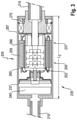
- FIG. 3 shows an embodiment according to the invention, in which a much more compact construction of the actuator can clearly be seen.
- the planetary transmission 260 is designed analogously to the transmission in FIG. 2 and is disposed here within the E-Motor 250 .
- the control unit or electronics 240 , respectively, of the actuator 235 is accommodated analogously to the arrangement according to FIG. 2 .
- the transmission does not axially extend substantially beyond the Vernier motor.
- the ring gear 256 is positioned inside of the rotor 252 and supported on the housing 235 via a support member 267 .
- the width of the actuator 235 can be reduced to L 2 by approximately 2 ⁇ 3 to 1 ⁇ 2 the width L 1 of the actuator 135 of FIG. 2 (in accordance with the state of the technology). This is especially possible because the Vernier motor, in this case with a hollow rotor, takes up less space and can accommodate the transmission in its interior. It is obvious, in accordance with FIG. 2 , that in a conventional E-Motor a transmission cannot be integrated in the E-Motor.
Landscapes
- Engineering & Computer Science (AREA)
- Mechanical Engineering (AREA)
- Power Engineering (AREA)
- Vehicle Body Suspensions (AREA)
Abstract
Description
- 100 Vehicle
- 105, 205 Roll Stabilizer
- 110, 210 first Stabilizer Element
- 115, 215 second Stabilizer Element
- 120 first Wheel Suspension Element
- 120 a first Hinged Support
- 125 second Wheel Suspension Element
- 125 a second Hinged Support
- 130 Structure Bearing
- 135, 235 Actuator
- 137, 237 Housing
- 140, 240 Control Unit, Electronics
- 150, 250 Electric Motor
- 152, 252 Rotor
- 155, 255 Stator
- 160, 260 Transmission
- 161 a,b,c Planetary Stage
- 162 a,b,c Sun Gear
- 164 a,b,c Planetary Carrier
- 166, 266 Ring Gear
- 170, 270 Output Drive
Claims (10)
Applications Claiming Priority (3)
| Application Number | Priority Date | Filing Date | Title |
|---|---|---|---|
| DE102017207116.8A DE102017207116A1 (en) | 2017-04-27 | 2017-04-27 | Anti-roll stabilizer and use of a roll stabilizer in a motor vehicle |
| DE102017207116.8 | 2017-04-27 | ||
| PCT/EP2018/057695 WO2018197137A1 (en) | 2017-04-27 | 2018-03-27 | Roll stabilizer and use of a roll stabilizer in a motor vehicle |
Publications (2)
| Publication Number | Publication Date |
|---|---|
| US20200198434A1 US20200198434A1 (en) | 2020-06-25 |
| US11247526B2 true US11247526B2 (en) | 2022-02-15 |
Family
ID=61911543
Family Applications (1)
| Application Number | Title | Priority Date | Filing Date |
|---|---|---|---|
| US16/608,250 Expired - Fee Related US11247526B2 (en) | 2017-04-27 | 2018-03-27 | Roll stabilizer and use of a roll stabilizer in a motor vehicle |
Country Status (4)
| Country | Link |
|---|---|
| US (1) | US11247526B2 (en) |
| EP (1) | EP3615360A1 (en) |
| DE (1) | DE102017207116A1 (en) |
| WO (1) | WO2018197137A1 (en) |
Cited By (2)
| Publication number | Priority date | Publication date | Assignee | Title |
|---|---|---|---|---|
| US20210394579A1 (en) * | 2019-01-26 | 2021-12-23 | Soon Gil Jang | Stabilizer for vehicle |
| US20230027163A1 (en) * | 2021-07-20 | 2023-01-26 | Hyundai Mobis Co., Ltd. | Steering reaction force apparatus for vehicle |
Families Citing this family (1)
| Publication number | Priority date | Publication date | Assignee | Title |
|---|---|---|---|---|
| KR102184282B1 (en) * | 2020-08-13 | 2020-11-30 | 권정우 | Electric motor with integral gearbox |
Citations (17)
| Publication number | Priority date | Publication date | Assignee | Title |
|---|---|---|---|---|
| US2931248A (en) * | 1959-03-23 | 1960-04-05 | United Shoe Machinery Corp | Strain wave gearing-strain inducer species |
| US4757220A (en) | 1984-02-29 | 1988-07-12 | Alsthom | Electrodynamic vernier machine |
| EP1187302A2 (en) * | 2000-07-28 | 2002-03-13 | Japan Servo Co. Ltd. | Motor-driven system with toothed stator poles |
| DE10243809A1 (en) | 2002-03-13 | 2004-05-19 | Robert Bosch Gmbh | actuator |
| US20040245887A1 (en) | 2001-08-08 | 2004-12-09 | Hiroyasu Fujinaka | Brush-less motor using vernier structure |
| US20050236793A1 (en) * | 2003-03-28 | 2005-10-27 | Aisin Seiki Kabushiki Kaisha | Stabilizer control device for vehicle |
| WO2006135088A1 (en) | 2005-06-16 | 2006-12-21 | Toyota Jidosha Kabushiki Kaisha | Vehicle stabilizer system |
| EP1820675A1 (en) | 2006-02-21 | 2007-08-22 | Zf Friedrichshafen Ag | Stabiliser assembly |
| DE102006058133A1 (en) | 2006-12-09 | 2008-06-19 | Zf Friedrichshafen Ag | Actuator for roll stabilization |
| DE102008041415A1 (en) | 2008-08-21 | 2010-02-25 | Zf Lenksysteme Gmbh | Electrical power steering system i.e. servo steering system, for vehicle, has servo-motor arranged in rack, and electrical rolling stabilizer assigned to rack and forming part of rolling stabilization system for axle of vehicle |
| WO2013189649A1 (en) | 2012-06-18 | 2013-12-27 | Robert Bosch Gmbh | Electric motor with planetary gear unit |
| US20150069875A1 (en) | 2013-09-09 | 2015-03-12 | Wisconsin Alumni Research Foundation | Double air gap, spoke type vernier machine |
| DE102015206064A1 (en) | 2015-04-02 | 2016-10-06 | Schaeffler Technologies AG & Co. KG | Roll stabilizer for a multi-track motor vehicle |
| WO2016155715A1 (en) | 2015-04-02 | 2016-10-06 | Schaeffler Technologies AG & Co. KG | Gear for a gear train |
| US20180056172A1 (en) | 2013-04-12 | 2018-03-01 | Angel Playing Cards Co., Ltd. | Card game system and method of a table game |
| WO2018197134A1 (en) * | 2017-04-27 | 2018-11-01 | Zf Friedrichshafen Ag | Roll stabiliser and use of a roll stabiliser in a motor vehicle |
| US20210009190A1 (en) * | 2019-07-11 | 2021-01-14 | Jilin University | Dual-mode active rear-wheel steering device |
-
2017
- 2017-04-27 DE DE102017207116.8A patent/DE102017207116A1/en not_active Ceased
-
2018
- 2018-03-27 EP EP18716150.0A patent/EP3615360A1/en not_active Withdrawn
- 2018-03-27 US US16/608,250 patent/US11247526B2/en not_active Expired - Fee Related
- 2018-03-27 WO PCT/EP2018/057695 patent/WO2018197137A1/en not_active Ceased
Patent Citations (19)
| Publication number | Priority date | Publication date | Assignee | Title |
|---|---|---|---|---|
| US2931248A (en) * | 1959-03-23 | 1960-04-05 | United Shoe Machinery Corp | Strain wave gearing-strain inducer species |
| US4757220A (en) | 1984-02-29 | 1988-07-12 | Alsthom | Electrodynamic vernier machine |
| EP1187302A2 (en) * | 2000-07-28 | 2002-03-13 | Japan Servo Co. Ltd. | Motor-driven system with toothed stator poles |
| US20040245887A1 (en) | 2001-08-08 | 2004-12-09 | Hiroyasu Fujinaka | Brush-less motor using vernier structure |
| DE10243809A1 (en) | 2002-03-13 | 2004-05-19 | Robert Bosch Gmbh | actuator |
| US20050236793A1 (en) * | 2003-03-28 | 2005-10-27 | Aisin Seiki Kabushiki Kaisha | Stabilizer control device for vehicle |
| WO2006135088A1 (en) | 2005-06-16 | 2006-12-21 | Toyota Jidosha Kabushiki Kaisha | Vehicle stabilizer system |
| EP1820675A1 (en) | 2006-02-21 | 2007-08-22 | Zf Friedrichshafen Ag | Stabiliser assembly |
| DE102006058133A1 (en) | 2006-12-09 | 2008-06-19 | Zf Friedrichshafen Ag | Actuator for roll stabilization |
| US20100072725A1 (en) | 2006-12-09 | 2010-03-25 | Zf Friedrichshafen Ag | Actuator for generating a rotational positioning movement |
| DE102008041415A1 (en) | 2008-08-21 | 2010-02-25 | Zf Lenksysteme Gmbh | Electrical power steering system i.e. servo steering system, for vehicle, has servo-motor arranged in rack, and electrical rolling stabilizer assigned to rack and forming part of rolling stabilization system for axle of vehicle |
| WO2013189649A1 (en) | 2012-06-18 | 2013-12-27 | Robert Bosch Gmbh | Electric motor with planetary gear unit |
| US20180056172A1 (en) | 2013-04-12 | 2018-03-01 | Angel Playing Cards Co., Ltd. | Card game system and method of a table game |
| US20150069875A1 (en) | 2013-09-09 | 2015-03-12 | Wisconsin Alumni Research Foundation | Double air gap, spoke type vernier machine |
| DE102015206064A1 (en) | 2015-04-02 | 2016-10-06 | Schaeffler Technologies AG & Co. KG | Roll stabilizer for a multi-track motor vehicle |
| WO2016155715A1 (en) | 2015-04-02 | 2016-10-06 | Schaeffler Technologies AG & Co. KG | Gear for a gear train |
| US10330188B2 (en) | 2015-04-02 | 2019-06-25 | Schaeffler Technologies AG & Co. KG | Gear for a gear train |
| WO2018197134A1 (en) * | 2017-04-27 | 2018-11-01 | Zf Friedrichshafen Ag | Roll stabiliser and use of a roll stabiliser in a motor vehicle |
| US20210009190A1 (en) * | 2019-07-11 | 2021-01-14 | Jilin University | Dual-mode active rear-wheel steering device |
Non-Patent Citations (6)
| Title |
|---|
| Description Translation for EP 1820675 from Espacenet (Year: 2007). * |
| Description Translation for WO 2013/189649 from Espacenet (Year: 2013). * |
| Description Translation for WO 2016/155715 from Espacenet (Year: 2016). * |
| German Office Action Corresponding to 10 2017 207 116.8 dated Mar. 21, 2018. |
| International Search Report Corresponding to PCT/EP2018/057695 dated Jul. 19, 2018. |
| Written Opinion Corresponding to PCT/EP2018/057695 dated Jul. 19, 2018. |
Cited By (5)
| Publication number | Priority date | Publication date | Assignee | Title |
|---|---|---|---|---|
| US20210394579A1 (en) * | 2019-01-26 | 2021-12-23 | Soon Gil Jang | Stabilizer for vehicle |
| US11731481B2 (en) * | 2019-01-26 | 2023-08-22 | Soon Gil Jang | Stabilizer for vehicle |
| US20230347704A1 (en) * | 2019-01-26 | 2023-11-02 | Soon Gil Jang | Stabilizer for vehicle |
| US20230027163A1 (en) * | 2021-07-20 | 2023-01-26 | Hyundai Mobis Co., Ltd. | Steering reaction force apparatus for vehicle |
| US11724731B2 (en) * | 2021-07-20 | 2023-08-15 | Hyundai Mobis Co., Ltd. | Steering reaction force apparatus for vehicle |
Also Published As
| Publication number | Publication date |
|---|---|
| WO2018197137A1 (en) | 2018-11-01 |
| US20200198434A1 (en) | 2020-06-25 |
| DE102017207116A1 (en) | 2018-10-31 |
| EP3615360A1 (en) | 2020-03-04 |
Similar Documents
| Publication | Publication Date | Title |
|---|---|---|
| US8573604B2 (en) | Wheel suspension for a motor vehicle | |
| US11247526B2 (en) | Roll stabilizer and use of a roll stabilizer in a motor vehicle | |
| EP1733912B1 (en) | Vehicle having in-wheel motor | |
| JP5945287B2 (en) | Wheel drive device for vehicle capable of electric drive | |
| US6550788B2 (en) | Electromechanical stabilizer for a vehicle chassis | |
| CN104033534B (en) | Electromechanical vibroshock | |
| JP5207067B2 (en) | Variable stiffness stabilizer | |
| CN103097153B (en) | For the electric shock absorber of self-propelled vehicle | |
| DE102007031203A1 (en) | stabilizer assembly | |
| CN104955665A (en) | Gearbox for an adjustable vehicle stabilizer, and vehicle stabilizer | |
| CN107636347A (en) | Swing stabilizing device for multi-train wheeled motor vehicle | |
| US20120309578A1 (en) | Arrangement For Driving A Vehicle Wheel With A Drive Motor | |
| US20160089951A1 (en) | Active rotary stabilizer and stabilizer bar link assembly for vehicle | |
| CN103582578A (en) | Wheel Suspension Structure with Rotational Damper | |
| CN107683380A (en) | Gear for a gear transmission | |
| US7413196B2 (en) | Stabilizer assembly unit | |
| KR20170121520A (en) | Reducer for active stabilizer | |
| US7841602B2 (en) | Active, divided motor vehicle stabilizer having installed electric pivot motor | |
| KR20170000150A (en) | Ars system enhancing the damping structure | |
| KR20190141723A (en) | Uses of roll stabilizers for use in roll stabilizers and automobiles | |
| CN111347857A (en) | Electric drive axle and vehicle | |
| CN208558999U (en) | A kind of electricity drives axle assembly and vehicle | |
| CN112855862A (en) | Speed reducer | |
| CN110901358B (en) | Electric bridge drive system and vehicle | |
| CN217294507U (en) | Novel electric flat carriage transmission system and novel electric flat carriage |
Legal Events
| Date | Code | Title | Description |
|---|---|---|---|
| AS | Assignment |
Owner name: ZF FRIEDRICHSHAFEN AG, GERMANY Free format text: ASSIGNMENT OF ASSIGNORS INTEREST;ASSIGNORS:KLANK, MICHAEL;ELBERS, CHRISTOPH;HAEGELE, ALEXANDER;AND OTHERS;REEL/FRAME:050823/0459 Effective date: 20191008 |
|
| FEPP | Fee payment procedure |
Free format text: ENTITY STATUS SET TO UNDISCOUNTED (ORIGINAL EVENT CODE: BIG.); ENTITY STATUS OF PATENT OWNER: LARGE ENTITY |
|
| STPP | Information on status: patent application and granting procedure in general |
Free format text: DOCKETED NEW CASE - READY FOR EXAMINATION |
|
| STPP | Information on status: patent application and granting procedure in general |
Free format text: NON FINAL ACTION MAILED |
|
| STPP | Information on status: patent application and granting procedure in general |
Free format text: RESPONSE TO NON-FINAL OFFICE ACTION ENTERED AND FORWARDED TO EXAMINER |
|
| STPP | Information on status: patent application and granting procedure in general |
Free format text: FINAL REJECTION MAILED |
|
| STPP | Information on status: patent application and granting procedure in general |
Free format text: RESPONSE AFTER FINAL ACTION FORWARDED TO EXAMINER |
|
| STPP | Information on status: patent application and granting procedure in general |
Free format text: NOTICE OF ALLOWANCE MAILED -- APPLICATION RECEIVED IN OFFICE OF PUBLICATIONS |
|
| STPP | Information on status: patent application and granting procedure in general |
Free format text: AWAITING TC RESP., ISSUE FEE NOT PAID |
|
| STPP | Information on status: patent application and granting procedure in general |
Free format text: NOTICE OF ALLOWANCE MAILED -- APPLICATION RECEIVED IN OFFICE OF PUBLICATIONS |
|
| STPP | Information on status: patent application and granting procedure in general |
Free format text: PUBLICATIONS -- ISSUE FEE PAYMENT VERIFIED |
|
| STCF | Information on status: patent grant |
Free format text: PATENTED CASE |
|
| FEPP | Fee payment procedure |
Free format text: MAINTENANCE FEE REMINDER MAILED (ORIGINAL EVENT CODE: REM.); ENTITY STATUS OF PATENT OWNER: LARGE ENTITY |
|
| LAPS | Lapse for failure to pay maintenance fees |
Free format text: PATENT EXPIRED FOR FAILURE TO PAY MAINTENANCE FEES (ORIGINAL EVENT CODE: EXP.); ENTITY STATUS OF PATENT OWNER: LARGE ENTITY |
|
| STCH | Information on status: patent discontinuation |
Free format text: PATENT EXPIRED DUE TO NONPAYMENT OF MAINTENANCE FEES UNDER 37 CFR 1.362 |
|
| FP | Lapsed due to failure to pay maintenance fee |
Effective date: 20260215 |