US1124635A - Lighting means for motion-picture auditoriums. - Google Patents
Lighting means for motion-picture auditoriums. Download PDFInfo
- Publication number
- US1124635A US1124635A US82959614A US1914829596A US1124635A US 1124635 A US1124635 A US 1124635A US 82959614 A US82959614 A US 82959614A US 1914829596 A US1914829596 A US 1914829596A US 1124635 A US1124635 A US 1124635A
- Authority
- US
- United States
- Prior art keywords
- box
- light
- auditorium
- screen
- audience
- Prior art date
- Legal status (The legal status is an assumption and is not a legal conclusion. Google has not performed a legal analysis and makes no representation as to the accuracy of the status listed.)
- Expired - Lifetime
Links
- 239000000463 material Substances 0.000 description 8
- 230000000694 effects Effects 0.000 description 2
- 238000005286 illumination Methods 0.000 description 2
- 229910052751 metal Inorganic materials 0.000 description 2
- 239000002184 metal Substances 0.000 description 2
- 239000003921 oil Substances 0.000 description 2
- 201000004569 Blindness Diseases 0.000 description 1
- 241000499489 Castor canadensis Species 0.000 description 1
- 235000011779 Menyanthes trifoliata Nutrition 0.000 description 1
- 229910052782 aluminium Inorganic materials 0.000 description 1
- XAGFODPZIPBFFR-UHFFFAOYSA-N aluminium Chemical compound [Al] XAGFODPZIPBFFR-UHFFFAOYSA-N 0.000 description 1
- 239000010425 asbestos Substances 0.000 description 1
- 230000000052 comparative effect Effects 0.000 description 1
- 238000010276 construction Methods 0.000 description 1
- 230000014509 gene expression Effects 0.000 description 1
- 238000004519 manufacturing process Methods 0.000 description 1
- 229910052895 riebeckite Inorganic materials 0.000 description 1
Images

Classifications
-
- F—MECHANICAL ENGINEERING; LIGHTING; HEATING; WEAPONS; BLASTING
- F21—LIGHTING
- F21S—NON-PORTABLE LIGHTING DEVICES; SYSTEMS THEREOF; VEHICLE LIGHTING DEVICES SPECIALLY ADAPTED FOR VEHICLE EXTERIORS
- F21S41/00—Illuminating devices specially adapted for vehicle exteriors, e.g. headlamps
Definitions
- FRANK G MCPEERSON, E BEAVER FALLS, PENllSYLVANIA, ASSIGNOR TO SHADO- LITE MANUFACTURING 00., INC, BEAVER FALLS, PENNSYLVANIA, it S33E30- RATIOIQ' L DELAWARE.
- This invention has reference to improvements in lighting means for motion picture 1 auditoriurns, and its object is to provide lighting means whereby that part of the auditorium occupied by the audience is well lighted while the screen upon which the pictures are exhibited is shielded from the light source, and the eyes of the audience are also shielded from the light source.
- lighting units with reflecting shields so arranged that beams of light'areprojected forwardly or screenward and also downwardly upon the audience from that portion of the auditorium. distant from the screen, whereby the auditorium in that part occupied by the audience is sufficiently well lighted so that any one can see distinctly about the auditorium, but the ceiling and a portion of the side walls, and particularly the screen, are
- a1 is the shade.
- Such light .8 isaproiected toward the screen is projected against the backs of the people making up the audience and occupying the seats provided, wherefore the eyes of the audience are directed away from the source of light when looking upon the screen, and hence the audience is in no wise distracted by any lights in the line of vision except those upon the screen itself.
- the result is that the pictures upon the screen become sensibly intensified in brilliancy, while at the same time the audience portion of the auditorium is bathed in light which may be brilliant enough to perreading, wherefore the light be termed a reading light.
- Fig. 3 is a longitudinal section of a lighting unit at .pted for the lighting of motion picture auditoriunis.
- Fig. 4 is a. top plan viewthereof.
- Fig. 5 is a bottom plan view of the structure of Figs. 3 and 4.
- Fig. 6 is a section on the line 6-6 of Fig. 5.
- Fig. 7 is a side elevation with some-parts in section showing anattech ment to the structure of Fig. can asshciated figures.
- FIG. 3 there is shown an elongated rectangle box 1 comprising a top member 2, side members 3, and end members 4, 5, respectively, while the part which would .c0nstitute the bottom of the box is omitted: ex cept that there is a short section 6' at the end 5 of the box and extending for a distance toward the end 4, but the remainder of whatconstitutes the bottom of the box is open. It will be understood that the expressions of position have to do with the manner in which the box is mounted when in use.
- plane reflecting plates 7 diverging toward the open bottom of the box, and of substantially the length of the box, except that at the end 4' there is provided a concave reflecting surface 8 curving from the bottom portion of the end 4: of the box in an upward direction toward the top 2 of the box, so that the upper end' of the curved surface 8 is closer to the end 5 of the box than the lower end of this reflecting surface.
- a socket 9 Opening into the interior of the box and arranged to receive an electric lamp 10 which in most cases may be a forty watt or a sixty watt Mazda lamp, but the size and style of the lamp are not essential to the present invention.
- the short bottom length of the box is suiliciently long to coact with the top, sides and end 5 of the box to house the lamp .0, so that any one directly under the box 1 and'looking upwardly would have the lamp hidden from view.
- a slide 11 is sometimes provided with the edges of this slide moving in side channels 12 of the short bottom .portion of the box, so that the hiding portion may be elongated by pulling out the slide 11.
- any suitable holder may be provided.
- a rod 13 is secured to the top of the box by clips 14, so that this rod extends for a considerable distance beyond what may be termed the back end 5 of the box.
- the rear end of the rod 13 extends through a sleeve I5 in which it is held by a set screw 16.
- the sleeve may be rotated upon an axialholder 17' and clamped in any suitable position of adjustment by a set screw 18.
- the holder 17 is carried by a'rod 19 which at the end remote from the holder 17 is lodged in a block 20, being made fast therein by a set screw 21.
- the block 20 is secured by a set screw 22 to a bracket 23 fast onv a wall plate 2% which in turn may be secured in any suitable manner to a supporting wall.
- the supporting structures 'described permit, the universal movement of the box 1 for-its adjustment for a purpose which Will hereinafter appear.
- the reflecting surfaces 7 have plane bottom marginal portions or edges 25 parallel with the sides 3 of the box,and the curved reflector 8 has a lower marginal portion 26 parallel with the front at of it produced, are light unit the box, and
- these particular portions serve as cut oils for the light directed toward them from the lamp 10 and in a manner accentuate the shadow line cast by the box itself, this box being of opaque material and therefore acting as a shield for the lamp.
- the box may be provided with an additional shield 27 con siderably wider than the width of the box, and considerably shorter than the length of the box, the shield 27 being curved away from the back end 5 of the frontend 4 thereof and dropping for a considerable distance below the open bottom of the box, wherefore when the lighting unit represented by the box 1 with its lamp and box toward the reflectors is placed in a position more or less 7 in front of a portion of the audience when parts of the unit liable to direct light to ward the eyes of the audience are shielded by the shield 27.
- This shield is an attachment for the light unit of Fig. 3 and associated figures, and is used only under certain conditions.
- an auditorium 28 is more or less schematically indicated, such auditorium being intended for the exhibition of motion pictures.
- the light'emitted from the lamp 10 passes out from the box directly through the open bottom thereof and is also directed by the reflectors 7,'
- the top and sides of the box or boxes 1 cast 7 shadows against theceilingbi theauditorium and portions of the. side walls, while the front 4 of the box shades the screen.
- the reflectors ,7 and S. as well as direct rays of light from the lamp 10 light up the portion of the auditorium occupied by the seats for the audience. :xctual tests masses 3 have shown that this lighting is suificient h is for ordinary reading, so that it may he termed reading lighting, but the screen is located in a marked shadow.
- lhe source of light is back of most of'the audience and the source of light is therefore 'far removed from the eyes of the audience,
- the general illumination of the auditorium is such as to make the audience clearly visible, and this to an extent permittin i the people entering the theater from a light street to find their way to seats without diiiiculty and without the temporary blindness so noticeable upon entering man motion picture theaters from a street in daylight or brilliantly lighted'et night
- the comparativelj, dense shadow at the screenend of the auditorium serves to terially accentuate the pictures on the screen, so that the pictures become sensibly more brilliant.
- the eyes of the audience do not become in any manner fatigued or distracted from the presence of the'sources of light more or less in the line of vision even though these sources of light be in part shielded, for even with indirect lighting ceiling of the auditorium is lighted up and that portion near the screen becomes risible to the audience, and especially those more remote from the screen.
- the lighting units 1 are so arranged that their front portions I ⁇ throw the screen into the shadow the same as in the arrangement of F ig. 1.
- the more forward lighting: unit or units 1 of Fig. 2 might prove ootrusive to thoseof the audience near the back of the auditorium and in such case the shields 27 are applied, so that the light units evexi in the arrangement of. F ig. 2 are not actually obtrusirely visible to any person in the audience, but they serve to compensate for the great distance which the rearmost' light units 1 are from the front or screen end of the auditorium when placed against the rear wall of the room.
- the arrangement of Fig. l is found to he ample, but in some of the more elongated ones the 3.1 'angement of Fig. 2 is advisable.
- box l has been described as of elongated rectangular shape, it will be understood that this box performs the otfice of a casing for protecting the light giving and reflecting elements, and hence; its shape and construction are not particularly essen tial to the present invention and under some circumstances might even be omitted in part, especially when the reflectors are made of opaque material such as polished aluminum pr nickle plated and polished cop- ,prising a source of light, reflectors asse ciated therewith, and light shielding means" mfich, asbestos board, and the like
- the rear shade which may be employed as an attachment to the lighting unit when the latter is used in a more forward position, that'is, nearer the screen than thoselightgiving elements stationed close to the operators booth, may be made of sheet metal or other suitable material either entirely impervious to light, or may be constructed so as to give an ornamental effect, in which case other materials than metal may be employed.
- the prime purpose of the additional shade is merely to shut; oil any light spots from the View of those persons in the audience sitting to the rear of the shaded light, so that even though the lighting unit be otherwise within their range of vision it presents no distracting view preventing the concentration of attendon upon the picture production.
- the lighting fixture or unit is so located in the auditorium as to leave nothing visible to the eye except that the audience is located ice outlines apparent to the audience, Where- 1G5 fore because of the possibility of full unob- Y structed concentration the picture being exhibited upon the screen appears more real and life like than is the case with the lighting systems in use in practically all motion 11G picture auditcriuzns.
- the cost of illuminating the auditorium is reduced because of the fewer lamps necessary and. since the screen is subjected to far less foreign 115 light than ordinar even in poorly lighted auditoriums when illuminated by the systems now in general use, the screen becomes hotter illuminated and more satisfactorilyilluminated so far as the audience is con cerned than heretofore, with respect to the sharp projected picture effect.
- a motion plcture auditorium provided with a picture-exhibiting screen at one end,
- illuminating means for the auditorium in elevated position therein and distant from. the screen, said illuminating means com inclosing the source of light and the reflectors and open on the under side in the directiontoward thescreen end of the auditorium to cause the direct and reflected light rays from the source of light to be projected toward the floor and toward the screen end of the auditorium, with the screen and the ceiling of the auditorium in the shadow produced by the light shielding means 2.
- a motion picture auditorium provided with a picture-exhibiting screen at one end, illuminating means for the auditorium in elevated position thereinand distant fromv the screen, said illuminating means comprising a source of light, reflectors associated therewith, and light shielding means inclosing the'source of light and the reflectors and open on the under side in the direction toward the screen end of the auditorium to cause the direct and reflected light rays from the source of light to be projected toward the floor and toward the screen end of the auditorium, with the screen and the ceiling of the auditorium in the shadow 25 produced by the light shielding means, said illuminating means with the reflecting means being elongated in the direction of the length of the auditorium toward the screen end thereof with the source of light at the end of the illuminating means distant from the screen.
- a motion picture auditorium provided with a screen at one end, and illuminating means therefor in elevated position in the auditorium and distant from the screen and comprising a plurality of elements located at the end of the auditorium remote from the screen and at points less remote from the screen, each element including a source of light, light reflecting means, and light shielding means in position one with relatlon to the other to project the light forwardly and downwardly toward the screen end of the auditorium with the screen and the ceiling of the auditorium in' the shadow produced by the light shielding means, and the illun'iinating elements being situated in the auditorium to be, out of the range of vision oi an audience facing the'screen,
- a motion picture auditorium provided with a screenat one enchand illuminating means therefor inclevated position in the auditorium and distant from the screenand comprising a plurality of elements located at the end of the auditorium remote from the screen and at points less remote from the screen, each element including a source of light, light reflectingmeans, and light.
- shielding means in position one with relationto the other to'project the light forwardly and d iwnward1y toward the screen end of the auditorium, with the screen and the ceiling of the auditorium in the shadow produced by the light shielding means, and
- the illuminating elements being situated in the auditorium to be out of the range of vision of an audience facing the screen, those illuminating elements nearer to the screen having shielding means of a size to be wholly interposed between the light emitting and reflecting means of said illuminating elements and the eyes of those members of the audience more distant from the screen than the said illuminating elements.
- An illuminating element for a motion picture auditorium comprising an elongated box of opaque material closed at the top, sides and ends and having a closed bottom extending for a fractional portion of the length of the box from one end thereof, a light giving means lodged in that portion of the box defined by the closed bottom part, divergent reflectors extending lengthwise of the box and having their reflecting surfaces directed toward the open portion of the bottom of the box, and, means for supporting the box'in position to light up the floor of the auditorium and to place the screen and ceiling of the auditorium in the shadow produced by the opaque top, sides and end of the'box remote from the light givin means.
- illuminating element for a, motion picture auditorium comprising an elem gated box of opaque material closed at the top, sides and ends and having a closed bottom extending for a fractional portion of the length of the box from one end thereof, a light giving meanslodged in that portion of the box defined by the closed bottom part, divergent reflectors extending lengthwise of the box and having their reflecting surfaces directed toward the open portion of the bottom of the box, and means for supporting the box in position to light up the floor ofthe auditorium and to place the screen and ceiling of the auditorium inthe shadow produced by the opaque top, sides and end of-the box remote from the light giving means, said box having within it at the end distant from the light giving means a reflecting means curved from the bottom of the box upwagdly and toward the other end ofthe box.
- An illuminating means for motion picture auditoriums comprising an elongated box having a top, sides and ends of opaque material with the bottom closed for a free tional portion of its lengthQand the remainder of the bottom open, said closed portion being provided with an opaque slide movable 'le'ngthwise'of the box for increasing the efiective length ofvthe closed portioirof the bottom of the.box, light giving means in that end of the box defined by the closed bottom, and reflecting means in the box' for projecting light out through the open portionof the bottom of the box in a. directionlengthwise of the bottom of the box and away from the source'of light.
Landscapes
- Engineering & Computer Science (AREA)
- General Engineering & Computer Science (AREA)
- Non-Portable Lighting Devices Or Systems Thereof (AREA)
Description
F, G. MQPHERSON. LIGHTING MEANS FOR MOTION PICTURE AUDITORIUMS.
APPLICATION FILED APR. 4, I914.
Patented Jan. 12, 1915.
2 SHEETS-SHEET 1.
8% W .MP/zenrbm WENT) WITNESSES ATTORNEY APPLICATION FILED APR. 4, 1914.
Patented Jan. 12, 1915.
2 SHEBTSSHEBT 2.
WITNESSES ATTORN E UjillTED eras earnnr coerce.
FRANK G. MCPEERSON, E BEAVER FALLS, PENllSYLVANIA, ASSIGNOR TO SHADO- LITE MANUFACTURING 00., INC, BEAVER FALLS, PENNSYLVANIA, it S33E30- RATIOIQ' L DELAWARE.
icense.
Specification of Iiettez's E'atent.
.Application filed April 4-, 1914.. Serial No. 829,596.
7 To all whom it may call-067m:
Be it known that l, FRANK G. MGPHER- sox, a citizen of the United States, residing at Beaver Falls, in the county of Beaver and State of Pennsylvania. have invented a new and useful Lighting Means for Motion- Picture Auditoriums, of which the following is a specification. 1
This invention has reference to improvements in lighting means for motion picture 1 auditoriurns, and its object is to provide lighting means whereby that part of the auditorium occupied by the audience is well lighted while the screen upon which the pictures are exhibited is shielded from the light source, and the eyes of the audience are also shielded from the light source.
There is a continually increasing urgent demand for ample lighting of the auditoriums of motion picture theaters, but because of the interference of auditorium light with the efi'ect of the picture thrown upon the? screen diiliculty has been experienced in obtaining the desirable lighting of the auditorium without at the same time in teriering to a material extent with the exhibition of the pictures. The customary practice is to employ shielded side lights or indirect ceiling lighting, or a combination of the two, but such lighting schemes, although largely used, are objectionable in that the screen is noticeably lighted by the auditorium illumination and the eyes of the beholders are more or less disagreeably affected by those lighting units which are placed toward the screen end of'the audi-' toriuni.
By the present invention. ample lighting is provided for that part of the auditorium occupied by the audience, while the screen is in the shade and the lightin unit or units are so located as to be invisi le 'to the'au- LllnCB as seated and gazing upon the screen.
This is accomplished by providing lighting units with reflecting shields so arranged that beams of light'areprojected forwardly or screenward and also downwardly upon the audience from that portion of the auditorium. distant from the screen, whereby the auditorium in that part occupied by the audience is sufficiently well lighted so that any one can see distinctly about the auditorium, but the ceiling and a portion of the side walls, and particularly the screen, are
a1 is the shade. Such light .8 isaproiected toward the screen is projected against the backs of the people making up the audience and occupying the seats provided, wherefore the eyes of the audience are directed away from the source of light when looking upon the screen, and hence the audience is in no wise distracted by any lights in the line of vision except those upon the screen itself. The result is that the pictures upon the screen become sensibly intensified in brilliancy, while at the same time the audience portion of the auditorium is bathed in light which may be brilliant enough to perreading, wherefore the light be termed a reading light.
"The invention will be best understood them a. consideration of the following detailed description, taken in connection with Patented Jan. 12, 1915.
the accompanying drawings forming a part scheme of Fi 1. Fig. 3 is a longitudinal section of a lighting unit at .pted for the lighting of motion picture auditoriunis. Fig. 4 is a. top plan viewthereof. Fig. 5 is a bottom plan view of the structure of Figs. 3 and 4. Fig. 6 is a section on the line 6-6 of Fig. 5. Fig; 7 is a side elevation with some-parts in section showing anattech ment to the structure of Fig. can asshciated figures. Fig.3 is a section =-on"the line 8-8 of Fig. 7. v N
Referring first-to Fig. 3 and associated figures, there is shown an elongated rectangle box 1 comprising a top member 2, side members 3, and end members 4, 5, respectively, while the part which would .c0nstitute the bottom of the box is omitted: ex cept that there is a short section 6' at the end 5 of the box and extending for a distance toward the end 4, but the remainder of whatconstitutes the bottom of the box is open. It will be understood that the expressions of position have to do with the manner in which the box is mounted when in use.
Extending from the center line of the inner face of the top 2 of the box toward the lower edges of the sides 3 are plane reflecting plates 7 diverging toward the open bottom of the box, and of substantially the length of the box, except that at the end 4' there is provided a concave reflecting surface 8 curving from the bottom portion of the end 4: of the box in an upward direction toward the top 2 of the box, so that the upper end' of the curved surface 8 is closer to the end 5 of the box than the lower end of this reflecting surface.
Carried by the end 5 of the box is a socket 9 opening into the interior of the box and arranged to receive an electric lamp 10 which in most cases may be a forty watt or a sixty watt Mazda lamp, but the size and style of the lamp are not essential to the present invention. The short bottom length of the box is suiliciently long to coact with the top, sides and end 5 of the box to house the lamp .0, so that any one directly under the box 1 and'looking upwardly would have the lamp hidden from view. To increase the extent of hiding from VlCW of the lamp, a slide 11 is sometimes provided with the edges of this slide moving in side channels 12 of the short bottom .portion of the box, so that the hiding portion may be elongated by pulling out the slide 11.
In order to support the box in the mannor to be described, any suitable holder may be provided. n'the particular showing of the drawings a rod 13 is secured to the top of the box by clips 14, so that this rod extends for a considerable distance beyond what may be termed the back end 5 of the box. The rear end of the rod 13 extends through a sleeve I5 in which it is held by a set screw 16. The sleeve may be rotated upon an axialholder 17' and clamped in any suitable position of adjustment by a set screw 18. The holder 17 is carried by a'rod 19 which at the end remote from the holder 17 is lodged in a block 20, being made fast therein by a set screw 21. The block 20 is secured by a set screw 22 to a bracket 23 fast onv a wall plate 2% which in turn may be secured in any suitable manner to a supporting wall. The supporting structures 'described permit, the universal movement of the box 1 for-its adjustment for a purpose which Will hereinafter appear.
The reflecting surfaces 7 have plane bottom marginal portions or edges 25 parallel with the sides 3 of the box,and the curved reflector 8 has a lower marginal portion 26 parallel with the front at of it produced, are light unit the box, and
these particular portions serve as cut oils for the light directed toward them from the lamp 10 and in a manner accentuate the shadow line cast by the box itself, this box being of opaque material and therefore acting as a shield for the lamp.
T o prevent back reflections the box may be provided with an additional shield 27 con siderably wider than the width of the box, and considerably shorter than the length of the box, the shield 27 being curved away from the back end 5 of the frontend 4 thereof and dropping for a considerable distance below the open bottom of the box, wherefore when the lighting unit represented by the box 1 with its lamp and box toward the reflectors is placed in a position more or less 7 in front of a portion of the audience when parts of the unit liable to direct light to ward the eyes of the audience are shielded by the shield 27. This shield is an attachment for the light unit of Fig. 3 and associated figures, and is used only under certain conditions.
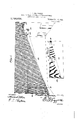
In Fig. 1 an auditorium 28 is more or less schematically indicated, such auditorium being intended for the exhibition of motion pictures. There is a screen 29 shown at one and of the auditorium, while the light emitting opening 30 of the operators booth is allso shown in Fig. 1. Near the ceiling of the auditorium and in most cases made fast to that wall through which the opening 30 found adrisabl to employ two such light units arranged on opposite sides of the openlng 30 and placed quite close to the boxes 1, it being ceiling of the auditorium. The light'emitted from the lamp 10 passes out from the box directly through the open bottom thereof and is also directed by the reflectors 7,'
and 8 in sidewise directions. The front 4 of the box with; the lower margin 26 of the reflector 8 casts a shadow in the direction of the length of the box and toward the screen 29 and by properly adjusting the box 1 where oneis'used, or the boxes 1 where more than oneis used, there isxproduced below the lower margin of the screen 291a shadow line indicated at 31, and all ofgth'e,
screen end of the auditorium above the'shoiyf line is in comparative darkness orishade while the side walls of the-auditorium ares,
lighted to progressively higher extentsfromr the shadow line 21 toward that end ofrthew,
auditorium adjacent to the operators booth. I
The top and sides of the box or boxes 1 cast 7 shadows against theceilingbi theauditorium and portions of the. side walls, while the front 4 of the box shades the screen. However, the reflectors ,7 and S. as well as direct rays of light from the lamp 10 light up the portion of the auditorium occupied by the seats for the audience. :xctual tests masses 3 have shown that this lighting is suificient h is for ordinary reading, so that it may he termed reading lighting, but the screen is located in a marked shadow. lhe source of light, however, is back of most of'the audience and the source of light is therefore 'far removed from the eyes of the audience,
although the general illumination of the auditorium is such as to make the audience clearly visible, and this to an extent permittin i the people entering the theater from a light street to find their way to seats without diiiiculty and without the temporary blindness so noticeable upon entering man motion picture theaters from a street in daylight or brilliantly lighted'et night The comparativelj, dense shadow at the screenend of the auditorium serves to terially accentuate the pictures on the screen, so that the pictures become sensibly more brilliant. lll'oreover, the eyes of the audience do not become in any manner fatigued or distracted from the presence of the'sources of light more or less in the line of vision even though these sources of light be in part shielded, for even with indirect lighting ceiling of the auditorium is lighted up and that portion near the screen becomes risible to the audience, and especially those more remote from the screen.
With the present invention it is possible .in elongated auditoriums to place one or more units 1 closer to the screen than in the arrangement shown in Fig. 1, this second arrangement being illustrated in Fig. 2, but
the lighting units 1 are so arranged that their front portions I} throw the screen into the shadow the same as in the arrangement of F ig. 1. The more forward lighting: unit or units 1 of Fig. 2 might prove ootrusive to thoseof the audience near the back of the auditorium and in such case the shields 27 are applied, so that the light units evexi in the arrangement of. F ig. 2 are not actually obtrusirely visible to any person in the audience, but they serve to compensate for the great distance which the rearmost' light units 1 are from the front or screen end of the auditorium when placed against the rear wall of the room. in many motion picture auditoriums the arrangement of Fig. l is found to he ample, but in some of the more elongated ones the 3.1 'angement of Fig. 2 is advisable.
While the box l has been described as of elongated rectangular shape, it will be understood that this box performs the otfice of a casing for protecting the light giving and reflecting elements, and hence; its shape and construction are not particularly essen tial to the present invention and under some circumstances might even be omitted in part, especially when the reflectors are made of opaque material such as polished aluminum pr nickle plated and polished cop- ,prising a source of light, reflectors asse ciated therewith, and light shielding means" mfich, asbestos board, and the like The rear shade which may be employed as an attachment to the lighting unit when the latter is used in a more forward position, that'is, nearer the screen than thoselightgiving elements stationed close to the operators booth, may be made of sheet metal or other suitable material either entirely impervious to light, or may be constructed so as to give an ornamental effect, in which case other materials than metal may be employed. The prime purpose of the additional shade is merely to shut; oil any light spots from the View of those persons in the audience sitting to the rear of the shaded light, so that even though the lighting unit be otherwise within their range of vision it presents no distracting view preventing the concentration of attendon upon the picture production.
= The lighting fixture or unit is so located in the auditorium as to leave nothing visible to the eye except that the audience is located ice outlines apparent to the audience, Where- 1G5 fore because of the possibility of full unob- Y structed concentration the picture being exhibited upon the screen appears more real and life like than is the case with the lighting systems in use in practically all motion 11G picture auditcriuzns.
Wlth the present invention the cost of illuminating the auditorium is reduced because of the fewer lamps necessary and. since the screen is subjected to far less foreign 115 light than ordinar even in poorly lighted auditoriums when illuminated by the systems now in general use, the screen becomes hotter illuminated and more satisfactorilyilluminated so far as the audience is con cerned than heretofore, with respect to the sharp projected picture effect.
What is claimed is i 1. A motion plcture auditorium provided with a picture-exhibiting screen at one end,
illuminating means for the auditorium in elevated position therein and distant from. the screen, said illuminating means com inclosing the source of light and the reflectors and open on the under side in the directiontoward thescreen end of the auditorium to cause the direct and reflected light rays from the source of light to be projected toward the floor and toward the screen end of the auditorium, with the screen and the ceiling of the auditorium in the shadow produced by the light shielding means 2. A motion picture auditorium provided with a picture-exhibiting screen at one end, illuminating means for the auditorium in elevated position thereinand distant fromv the screen, said illuminating means comprising a source of light, reflectors associated therewith, and light shielding means inclosing the'source of light and the reflectors and open on the under side in the direction toward the screen end of the auditorium to cause the direct and reflected light rays from the source of light to be projected toward the floor and toward the screen end of the auditorium, with the screen and the ceiling of the auditorium in the shadow 25 produced by the light shielding means, said illuminating means with the reflecting means being elongated in the direction of the length of the auditorium toward the screen end thereof with the source of light at the end of the illuminating means distant from the screen.
3. A motion picture auditorium provided with a screen at one end, and illuminating means therefor in elevated position in the auditorium and distant from the screen and comprising a plurality of elements located at the end of the auditorium remote from the screen and at points less remote from the screen, each element including a source of light, light reflecting means, and light shielding means in position one with relatlon to the other to project the light forwardly and downwardly toward the screen end of the auditorium with the screen and the ceiling of the auditorium in' the shadow produced by the light shielding means, and the illun'iinating elements being situated in the auditorium to be, out of the range of vision oi an audience facing the'screen,
at. A motion picture auditorium provided with a screenat one enchand illuminating means therefor inclevated position in the auditorium and distant from the screenand comprising a plurality of elements located at the end of the auditorium remote from the screen and at points less remote from the screen, each element including a source of light, light reflectingmeans, and light. shielding means in position one with relationto the other to'project the light forwardly and d iwnward1y toward the screen end of the auditorium, with the screen and the ceiling of the auditorium in the shadow produced by the light shielding means, and
i the illuminating elements being situated in the auditorium to be out of the range of vision of an audience facing the screen, those illuminating elements nearer to the screen having shielding means of a size to be wholly interposed between the light emitting and reflecting means of said illuminating elements and the eyes of those members of the audience more distant from the screen than the said illuminating elements.
5. An illuminating element for a motion picture auditorium, comprising an elongated box of opaque material closed at the top, sides and ends and having a closed bottom extending for a fractional portion of the length of the box from one end thereof, a light giving means lodged in that portion of the box defined by the closed bottom part, divergent reflectors extending lengthwise of the box and having their reflecting surfaces directed toward the open portion of the bottom of the box, and, means for supporting the box'in position to light up the floor of the auditorium and to place the screen and ceiling of the auditorium in the shadow produced by the opaque top, sides and end of the'box remote from the light givin means. I
6. illuminating element for a, motion picture auditorium, comprising an elem gated box of opaque material closed at the top, sides and ends and having a closed bottom extending for a fractional portion of the length of the box from one end thereof, a light giving meanslodged in that portion of the box defined by the closed bottom part, divergent reflectors extending lengthwise of the box and having their reflecting surfaces directed toward the open portion of the bottom of the box, and means for supporting the box in position to light up the floor ofthe auditorium and to place the screen and ceiling of the auditorium inthe shadow produced by the opaque top, sides and end of-the box remote from the light giving means, said box having within it at the end distant from the light giving means a reflecting means curved from the bottom of the box upwagdly and toward the other end ofthe box.
4 7. An illuminating means for motion picture auditoriums comprising an elongated box having a top, sides and ends of opaque material with the bottom closed for a free tional portion of its lengthQand the remainder of the bottom open, said closed portion being provided with an opaque slide movable 'le'ngthwise'of the box for increasing the efiective length ofvthe closed portioirof the bottom of the.box, light giving means in that end of the box defined by the closed bottom, and reflecting means in the box' for projecting light out through the open portionof the bottom of the box in a. directionlengthwise of the bottom of the box and away from the source'of light.
Priority Applications (1)
| Application Number | Priority Date | Filing Date | Title |
|---|---|---|---|
| US82959614A US1124635A (en) | 1914-04-04 | 1914-04-04 | Lighting means for motion-picture auditoriums. |
Applications Claiming Priority (1)
| Application Number | Priority Date | Filing Date | Title |
|---|---|---|---|
| US82959614A US1124635A (en) | 1914-04-04 | 1914-04-04 | Lighting means for motion-picture auditoriums. |
Publications (1)
| Publication Number | Publication Date |
|---|---|
| US1124635A true US1124635A (en) | 1915-01-12 |
Family
ID=3192792
Family Applications (1)
| Application Number | Title | Priority Date | Filing Date |
|---|---|---|---|
| US82959614A Expired - Lifetime US1124635A (en) | 1914-04-04 | 1914-04-04 | Lighting means for motion-picture auditoriums. |
Country Status (1)
| Country | Link |
|---|---|
| US (1) | US1124635A (en) |
-
1914
- 1914-04-04 US US82959614A patent/US1124635A/en not_active Expired - Lifetime
Similar Documents
| Publication | Publication Date | Title |
|---|---|---|
| US2247969A (en) | Edge glow lighting system | |
| US2170377A (en) | Picture illumination | |
| US2556690A (en) | Lighting fixture for elongated tubular lamps having means to shield the lamps | |
| US2280534A (en) | Lighting fixture | |
| US2031361A (en) | Projection apparatus | |
| US1124635A (en) | Lighting means for motion-picture auditoriums. | |
| US1262394A (en) | Vehicle-lamp. | |
| US1683599A (en) | Luminair | |
| US2313838A (en) | Mirror illumination | |
| US1357034A (en) | Electric-light fixture | |
| US1598106A (en) | Automobile headlight | |
| US2124417A (en) | Lighting fixture | |
| US1326393A (en) | Electric-light fixture. | |
| US1480904A (en) | Highway illuminator | |
| US1007498A (en) | Illuminating device. | |
| US1626615A (en) | Illuminating means | |
| US1176475A (en) | Lighting means for auditoriums and other places. | |
| US1793200A (en) | Aisle light | |
| US2642523A (en) | Luminaire of the wall mounted type | |
| US2189577A (en) | Episcope | |
| USRE15624E (en) | Illuminating device | |
| US2183462A (en) | Lighting system | |
| US1141718A (en) | Screen for headlights and other lamps. | |
| US1127504A (en) | Apparatus for projecting images of transparent and opaque objects. | |
| US1459440A (en) | Aisle light |