US11245122B2 - Fuel cell system - Google Patents
Fuel cell system Download PDFInfo
- Publication number
- US11245122B2 US11245122B2 US15/662,533 US201715662533A US11245122B2 US 11245122 B2 US11245122 B2 US 11245122B2 US 201715662533 A US201715662533 A US 201715662533A US 11245122 B2 US11245122 B2 US 11245122B2
- Authority
- US
- United States
- Prior art keywords
- purging
- fuel cell
- control device
- amount
- electrolyte membrane
- Prior art date
- Legal status (The legal status is an assumption and is not a legal conclusion. Google has not performed a legal analysis and makes no representation as to the accuracy of the status listed.)
- Active, expires
Links
Images


Classifications
-
- H—ELECTRICITY
- H01—ELECTRIC ELEMENTS
- H01M—PROCESSES OR MEANS, e.g. BATTERIES, FOR THE DIRECT CONVERSION OF CHEMICAL ENERGY INTO ELECTRICAL ENERGY
- H01M8/00—Fuel cells; Manufacture thereof
- H01M8/04—Auxiliary arrangements, e.g. for control of pressure or for circulation of fluids
- H01M8/04223—Auxiliary arrangements, e.g. for control of pressure or for circulation of fluids during start-up or shut-down; Depolarisation or activation, e.g. purging; Means for short-circuiting defective fuel cells
- H01M8/04228—Auxiliary arrangements, e.g. for control of pressure or for circulation of fluids during start-up or shut-down; Depolarisation or activation, e.g. purging; Means for short-circuiting defective fuel cells during shut-down
-
- H—ELECTRICITY
- H01—ELECTRIC ELEMENTS
- H01M—PROCESSES OR MEANS, e.g. BATTERIES, FOR THE DIRECT CONVERSION OF CHEMICAL ENERGY INTO ELECTRICAL ENERGY
- H01M8/00—Fuel cells; Manufacture thereof
- H01M8/04—Auxiliary arrangements, e.g. for control of pressure or for circulation of fluids
- H01M8/04223—Auxiliary arrangements, e.g. for control of pressure or for circulation of fluids during start-up or shut-down; Depolarisation or activation, e.g. purging; Means for short-circuiting defective fuel cells
- H01M8/04231—Purging of the reactants
-
- H—ELECTRICITY
- H01—ELECTRIC ELEMENTS
- H01M—PROCESSES OR MEANS, e.g. BATTERIES, FOR THE DIRECT CONVERSION OF CHEMICAL ENERGY INTO ELECTRICAL ENERGY
- H01M8/00—Fuel cells; Manufacture thereof
- H01M8/02—Details
- H01M8/0289—Means for holding the electrolyte
-
- H—ELECTRICITY
- H01—ELECTRIC ELEMENTS
- H01M—PROCESSES OR MEANS, e.g. BATTERIES, FOR THE DIRECT CONVERSION OF CHEMICAL ENERGY INTO ELECTRICAL ENERGY
- H01M8/00—Fuel cells; Manufacture thereof
- H01M8/04—Auxiliary arrangements, e.g. for control of pressure or for circulation of fluids
- H01M8/04082—Arrangements for control of reactant parameters, e.g. pressure or concentration
-
- H—ELECTRICITY
- H01—ELECTRIC ELEMENTS
- H01M—PROCESSES OR MEANS, e.g. BATTERIES, FOR THE DIRECT CONVERSION OF CHEMICAL ENERGY INTO ELECTRICAL ENERGY
- H01M8/00—Fuel cells; Manufacture thereof
- H01M8/10—Fuel cells with solid electrolytes
- H01M8/1016—Fuel cells with solid electrolytes characterised by the electrolyte material
- H01M8/1018—Polymeric electrolyte materials
- H01M8/1041—Polymer electrolyte composites, mixtures or blends
- H01M8/1046—Mixtures of at least one polymer and at least one additive
-
- H—ELECTRICITY
- H01—ELECTRIC ELEMENTS
- H01M—PROCESSES OR MEANS, e.g. BATTERIES, FOR THE DIRECT CONVERSION OF CHEMICAL ENERGY INTO ELECTRICAL ENERGY
- H01M8/00—Fuel cells; Manufacture thereof
- H01M8/10—Fuel cells with solid electrolytes
- H01M2008/1095—Fuel cells with polymeric electrolytes
-
- Y—GENERAL TAGGING OF NEW TECHNOLOGICAL DEVELOPMENTS; GENERAL TAGGING OF CROSS-SECTIONAL TECHNOLOGIES SPANNING OVER SEVERAL SECTIONS OF THE IPC; TECHNICAL SUBJECTS COVERED BY FORMER USPC CROSS-REFERENCE ART COLLECTIONS [XRACs] AND DIGESTS
- Y02—TECHNOLOGIES OR APPLICATIONS FOR MITIGATION OR ADAPTATION AGAINST CLIMATE CHANGE
- Y02E—REDUCTION OF GREENHOUSE GAS [GHG] EMISSIONS, RELATED TO ENERGY GENERATION, TRANSMISSION OR DISTRIBUTION
- Y02E60/00—Enabling technologies; Technologies with a potential or indirect contribution to GHG emissions mitigation
- Y02E60/30—Hydrogen technology
- Y02E60/50—Fuel cells
Definitions
- the present disclosure relates to a fuel cell system.
- a fuel cell In a fuel cell, hydrogen peroxide is produced at a catalyst layer in an electrochemical reaction, and hydroxyl radicals are produced from the hydrogen peroxide.
- the hydroxyl radicals cause a reduction in the thickness of an electrolyte membrane and decrease the performance. Therefore, a fuel cell in which a radical inhibitor for inhibition of hydroxyl radicals is contained in a catalyst layer is known (for example, refer to Japanese Patent Application Publication No. 2006-244782).
- the radical inhibitor is eluted in water in the fuel cell, is accumulated in the electrolyte membrane, and is thus able to inhibit hydroxyl radicals even in the electrolyte membrane.
- the amount of the radical inhibitor accumulated in the electrolyte membrane increases.
- the proton transfer resistance of the electrolyte membrane increases, possibly leading to the degradation in the performance of the electrolyte membrane.
- the present disclosure provides a fuel cell system capable of maintaining the amount of a radical inhibitor accumulated in an electrolyte membrane at an appropriate amount.
- a first aspect of the present disclosure relates to a fuel cell system including: a fuel cell in which at least one of an anode electrode and a cathode electrode with an electrolyte membrane interposed therebetween from both sides contains a radical inhibitor; a purging device which performs a scavenging process of purging water in the fuel cell by supplying a purging gas into the fuel cell after a power generation stop request of the fuel cell is issued; and a purging control unit which sets a purging condition of the purging process so as to increase a purging power in stages or continuously as a correlation value correlated with the amount of the radical inhibitor accumulated in the electrolyte membrane changes with an increase in the accumulated amount.
- the purging power is increased compared to a case where the accumulated amount is small, and the amount of residual water in the fuel cell after power generation is stopped can be sufficiently reduced. Accordingly, elution of the radical inhibitor can be inhibited, and an increase in the amount of the radical inhibitor accumulated in the electrolyte membrane can be suppressed. Contrary to this, in the case where the accumulated amount of the radical inhibitor is small, compared to the case where the accumulated amount is large, the amount of the residual water in the fuel cell after the power generation is stopped can be maintained at an appropriate amount.
- elution of the radical inhibitor can be promoted to be accumulated in the electrolyte membrane, and thus hydroxyl radical can be inhibited.
- the amount of the radical inhibitor accumulated in the electrolyte membrane can be maintained at an appropriate amount.
- the purging control unit may increase the purging power by performing at least one of increasing a purging time, increasing a supply amount of the purging gas, decreasing a backpressure of the fuel cell, increasing an amplitude of pulsation of the purging gas, shortening a period of the pulsation of the purging gas, and raising a temperature of the fuel cell.
- the correlation value may be any one of an elapsed time from start of use of the fuel cell, a cumulative stop time which is a cumulative value of an operation stop time after the start of the use of the fuel cell, and the amount of cation impurities in the electrolyte membrane.
- a second aspect of the present disclosure relates to a fuel cell system including: a fuel cell in which at least one of an anode electrode and a cathode electrode with an electrolyte membrane interposed therebetween from both sides contains a radical inhibitor; a purging device which discharges water in the fuel cell by supplying a purging gas into the fuel cell after a power generation stop request of the fuel cell is issued; and an electronic control unit which is programmed to control the purging device so as to increase the amount of the discharged water as the amount of the radical inhibitor accumulated in the electrolyte membrane, which is indicated by a correlation value correlated with the amount of the radical inhibitor accumulated, increases.
- FIG. 1 is a schematic view of a fuel cell system mounted in a vehicle
- FIG. 2 is a sectional view illustrating a cell of a fuel cell
- FIG. 3A is a graph showing the relationship between the amount of Ce 3+ accumulated in an electrolyte membrane, the decomposition rate of the electrolyte membrane by hydroxyl radicals, and the proton transfer resistance of the electrolyte membrane;
- FIG. 3B is a graph showing the relationship between the amount of Ce 3+ accumulated in the electrolyte membrane and the proton transfer resistance of the electrolyte membrane;
- FIG. 4A is a flowchart showing an example of purging control performed by a control device
- FIG. 4B is a graph showing a purging time set on the basis of an elapsed time
- FIG. 5 is a flowchart showing a first modification example of the purging control performed by the control device
- FIG. 6 is a flowchart showing a second modification example of the purging control performed by the control device
- FIG. 7A is a flowchart showing a third modification example of the purging control performed by the control device.
- FIG. 7B is a graph showing changes in pressure in a cathode gas passage during a normal purging process and a pulsation purging process
- FIG. 8A is a flowchart showing a fourth modification example of the purging control performed by the control device.
- FIG. 8B is an example of a map defining the relationship between the elapsed time and the purging time
- FIG. 9 is a flowchart showing a fifth modification example of the purging control performed by the control device.
- FIG. 10A is a flowchart showing a sixth modification example of the purging control performed by the control device.
- FIG. 10B is a graph showing the purging time set on the basis of the amount of cation impurities
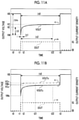
- FIG. 11A is a diagram for explaining a method of estimating the amount of cation impurities
- FIG. 11B is a diagram showing the difference between an output voltage in a case where the amount of cation impurities in the electrolyte membrane is small and the output voltage in a case where the amount of impurities is large;
- FIG. 12 is a partial enlarged view of FIG. 11B ;
- FIG. 13 is a graph showing an example of the relationship between the amount of cation impurities and a voltage drop amount
- FIG. 14 is a map defining the relationship between the proton transfer resistance and the amount of cation impurities at each relative humidity in the fuel cell.
- FIG. 1 is a schematic view of a fuel cell system 1 mounted in a vehicle.
- the vehicle is a fuel cell vehicle, an electric vehicle, a hybrid vehicle, or the like.
- the fuel cell system 1 can also be applied to various moving bodies (for example, ships, airplanes, and robots) other than vehicles and stationary power supplies.
- the fuel cell system 1 includes a fuel cell 20 , a control device 30 , a hydrogen gas supply system 120 , an air supply system 140 , and a cooling system 160 .
- the fuel cell system 1 supplies electrical power generated by the fuel cell 20 to a motor or the like for driving the vehicle.
- the control device 30 is a computer including a central processing unit (CPU), a read-only memory (ROM), a random-access memory (RAM), and the like and performs various types of control on the fuel cell system 1 by receiving sensor inputs from an ignition switch 101 , an accelerator pedal AP, and the like. In addition, the control device 30 performs purging control, which will be described later in detail.
- CPU central processing unit
- ROM read-only memory
- RAM random-access memory
- the fuel cell 20 is of a solid polymer electrolyte type in which a large number of unit cells (cells) are stacked, and is supplied with a fuel gas (for example, hydrogen) as a reaction gas and an oxidant gas (for example, air) to generate power.
- a fuel gas for example, hydrogen
- an oxidant gas for example, air
- the hydrogen gas supply system 120 supplies hydrogen to be supplied for power generation to the fuel cell 20 .
- the hydrogen gas supply system 120 includes a tank 110 , a hydrogen supply path 121 , a circulation path 122 , an emission path 123 , a tank valve 124 , a pressure regulating valve 125 , an injection valve 126 , a circulation pump 127 , a gas-liquid separator 128 , and an on/off valve 129 .
- Hydrogen gas is supplied from the tank 110 to the fuel cell 20 via the hydrogen supply path 121 .
- the tank valve 124 , the pressure regulating valve 125 , and the injection valve 126 are provided in order from the upstream side of the hydrogen supply path 121 .
- the circulation path 122 circulates anode off-gas discharged from the fuel cell 20 to the hydrogen supply path 121 .
- the amount of the hydrogen gas supplied is adjusted by controlling opening and closing of various valves by the control device 30 on the basis of the operation of the accelerator pedal AP.
- the circulation pump 127 and the gas-liquid separator 128 are provided on the circulation path 122 , and the circulation pump 127 circulates the anode off-gas separated by the gas-liquid separator 128 to the hydrogen supply path 121 .
- the water separated by the gas-liquid separator 128 and a portion of the anode off-gas are emitted to the emission path 142 via the emission path 123 branched from the gas-liquid separator 128 and the on/off valve 129 .
- the air supply system 140 supplies air to the fuel cell 20 .
- the air supply system 140 includes an air compressor 130 , an air supply path 141 , an emission path 142 , a bypass valve 145 , a muffler 146 , an intercooler 147 , and a bypass path 148 .
- the air taken in from the outside via an air cleaner 144 is compressed by the air compressor 130 via the air supply path 141 , is cooled by the intercooler 147 , and is supplied to the fuel cell 20 .
- the bypass valve 145 is provided at a branch point where the bypass path 148 branches from the air supply path 141 .
- the bypass valve 145 adjusts the flow rate of air supplied to the fuel cell 20 and the flow rate of air bypassing the fuel cell 20 via the bypass path 148 .
- the emission path 142 emits cathode off-gas discharged from the fuel cell 20 to the atmosphere, and is connected to an air outlet through which air is discharged from the fuel cell 20 .
- a pressure regulating valve 143 adjusts the flow rate of the cathode off-gas and backpressure on the cathode side.
- the amount of air supplied to the fuel cell 20 is adjusted by controlling various devices by the control device 30 on the basis of the operation of the accelerator pedal AP like the hydrogen gas.
- the muffler 146 is provided on the emission path 142 and reduces sound generated by the air passing through the emission path 142 .
- the cooling system 160 cools the fuel cell 20 by circulating a refrigerant through a predetermined path.
- the cooling system 160 includes a radiator 150 , a fan 152 , a circulation path 161 , a bypass path 162 , a three-way valve 163 , a circulation pump 164 , an ion exchanger 165 , a temperature sensor 168 , and a distribution path 169 .
- the refrigerant pumped by the circulation pump 164 flows through the circulation path 161 and transfers heat to the radiator 150 by the air blown by the fan 152 such that the refrigerant is cooled.
- the cooled refrigerant is supplied to the fuel cell 20 such that the fuel cell 20 is cooled.
- the temperature sensor 168 detects the temperature of the refrigerant discharged from the fuel cell 20 .
- the bypass path 162 branches from the circulation path 161 to bypass the radiator 150 , and the three-way valve 163 adjusts the flow rate of the refrigerant flowing through the bypass path 162 .
- the ion exchanger 165 is provided on the bypass path 162 to cause a portion of the refrigerant flowing through the bypass path 162 to flow therethrough.
- the distribution path 169 branches off from the circulation path 161 , is connected to the intercooler 147 , and is connected to the circulation path 161 again. Accordingly, the refrigerant is supplied to the intercooler 147 via the distribution path 169 , and the air passing through the intercooler 147 is cooled by the refrigerant.
- the control device 30 After a power generation stop request of the fuel cell 20 , the control device 30 performs purging control to discharge water in the fuel cell 20 by supplying purging gas into the fuel cell 20 .
- the purging control is realized by a purging device and a purging control unit, which are functionally realized by the CPU, the ROM, and the RAM of the control device 30 . Details will be described later.
- FIG. 2 is a sectional view illustrating the cell 10 of the fuel cell 20 .
- the cell 10 includes a membrane electrode assembly (MEA) 11 having an anode catalyst layer 14 a formed on one surface of an electrolyte membrane 12 and a cathode catalyst layer 14 c formed on the other surface thereof.
- MEA membrane electrode assembly
- the electrolyte membrane 12 is a solid polymer membrane formed of a fluorine-based resin material or a carbon-based resin material and has good proton conductivity in a wet state.
- the anode catalyst layer 14 a and the cathode catalyst layer 14 c include carbon particles (for example, carbon black) supporting a catalyst (for example, platinum or a platinum-cobalt alloy) that causes an electrochemical reaction to proceed, and an ionomer having proton conductivity.
- an anode side water-repellent layer 16 a a cathode side water-repellent layer 16 c forming a pair of water-repellent layers, and an anode gas diffusion layer 17 a and a cathode gas diffusion layer 17 c forming a pair of diffusion layers are disposed on both sides of the MEA 11 .
- the pair of water-repellent layers is provided to maintain the water contained in the MEA 11 at an appropriate amount.
- the MEA 11 , the pair of water-repellent layers, and the pair of gas diffusion layers are collectively referred to as a membrane electrode gas diffusion layer assembly (MEGA) 15 .
- MEGA membrane electrode gas diffusion layer assembly
- the anode side water-repellent layer 16 a , the cathode side water-repellent layer 16 c , the anode gas diffusion layer 17 a , and the cathode gas diffusion layer 17 c are formed of a member having gas permeability and electron conductivity, for example, a porous carbon member such as carbon cloth or carbon paper.
- an anode side separator 18 a and a cathode side separator 18 c forming a pair of separators with the MEGA 15 interposed therebetween are disposed on both sides of the MEGA 15 .
- the anode side separator 18 a and the cathode side separator 18 c are formed of a member having gas barrier properties and electronic conductivity, for example, a carbon member such as dense carbon formed by compressing carbon so as not to cause gas to permeate therethrough, or a metal member such as press-formed stainless steel.
- the anode side separator 18 a and the cathode side separator 18 c have uneven portions on the surfaces for forming gas passages through which gas flow.
- An anode gas passage 19 a is formed between the anode side separator 18 a and the anode gas diffusion layer 17 a .
- a cathode gas passage 19 c is formed between the cathode side separator 18 c and the cathode gas diffusion layer 17 c .
- the fuel gas flows through the anode gas passage 19 a
- the oxidant gas flows through the cathode gas passage 19 c .
- the anode catalyst layer 14 a , the anode side water-repellent layer 16 a , and the anode gas diffusion layer 17 a correspond to an anode electrode.
- the cathode catalyst layer 14 c , the cathode side water-repellent layer 16 c , and the cathode gas diffusion layer 17 c correspond to a cathode electrode.
- the gas diffusion layer is not limited thereto.
- One or both of the anode and the cathode may not be provided with the gas diffusion layer.
- gas is supplied from the anode gas passage or the cathode gas passage directly to the catalyst layer via the water-repellent layer.
- a sheet member having functions of water repellency, gas permeation, and conductivity may be used as the water-repellent layer.
- the anode side water-repellent layer 16 a and the cathode side water-repellent layer 16 c contain a radical inhibitor that inhibits the production of hydroxyl radicals.
- the radical inhibitor is a cerium-containing oxide, specifically CeO 2 .
- CeO 2 The principle that the production of radicals is inhibited by CeO 2 is as follows. During power generation by the fuel cell 20 , there may be cases where a portion of oxygen in the oxidant gas supplied to the fuel cell 20 permeates through the electrolyte membrane 12 and reaches the anode catalyst layer 14 a . When this oxygen is reduced in the anode catalyst layer 14 a , hydrogen peroxide is produced, and due to the hydrogen peroxide, hydroxyl radicals are generated.
- CeO 2 which is the radical inhibitor contained in the anode side water-repellent layer 16 a and the cathode side water-repellent layer 16 c is eluted as Ce 3+ in the water in the fuel cell 20 , and the hydroxyl radicals are consumed by the reaction of Formula (1). This inhibits the hydroxyl radicals. ⁇ OH+Ce 3+ +H + ⁇ Ce 4+ +H 2 O (1)
- ⁇ OH represents a hydroxyl radical
- the eluted Ce 3+ is gradually accumulated in the electrolyte membrane 12 with the usage time of the fuel cell 20 . Therefore, when more amount of Ce 3+ than necessary for inhibiting hydroxyl radicals is accumulated in the electrolyte membrane 12 , Ce 3+ increases the proton transfer resistance of the electrolyte membrane 12 as a cation impurity.
- FIG. 3A is a graph showing the relationship between the amount of Ce 3+ accumulated in the electrolyte membrane 12 , the decomposition rate of the electrolyte membrane 12 by the hydroxyl radicals, and the proton transfer resistance of the electrolyte membrane 12 .
- the amount of Ce 3+ accumulated in the electrolyte membrane 12 is too small, the decomposition rate of the electrolyte membrane 12 by the hydroxyl radicals increases.
- the amount of Ce 3+ accumulated in the electrolyte membrane 12 is too large, the proton transfer resistance increases.
- 3B is a graph showing the relationship between the amount of Ce 3+ accumulated in the electrolyte membrane 12 and the proton transfer resistance of the electrolyte membrane 12 and shows the relationship between the accumulated amount of Ce 3+ and the proton transfer resistance in a case where the relative humidity is 30 percent and 80 percent.
- the proton transfer resistance significantly increases as the relative humidity decreases. Therefore, in a case where the accumulated amount of Ce 3+ is more than an appropriate amount, the performance of the electrolyte membrane 12 is greatly degraded in a low wet state.
- the control device 30 of this example maintains the accumulated amount of Ce 3+ at an appropriate amount so as to suppress an increase in the proton transfer resistance while suppressing the decomposition rate of the electrolyte membrane 12 by the hydroxyl radicals.
- the amount of Ce 3+ eluted from the anode side water-repellent layer 16 a and the cathode side water-repellent layer 16 c increases in an environment with a large amount of liquid water in the fuel cell 20 , and increases as the time for which the anode side water-repellent layer 16 a and the cathode side water-repellent layer 16 c are exposed to the liquid water becomes longer.
- the anode side water-repellent layer 16 a and the cathode side water-repellent layer 16 c are exposed not only to the water produced during the power generation of the fuel cell 20 but also to the residual water in the fuel cell 20 after the power generation is stopped. Therefore, as the elapsed time from the start of operation of the fuel cell 20 (hereinafter, simply referred to as elapsed time) becomes longer, the cumulative value of the amount of Ce 3+ eluted from the anode side water-repellent layer 16 a and the cathode side water-repellent layer 16 c also increases, and accordingly the amount of Ce 3+ accumulated in the electrolyte membrane 12 also increases.
- the elapsed time of the fuel cell 20 is a correlation value correlated with the amount of Ce 3+ accumulated in the electrolyte membrane 12 .
- the elapsed time is the elapsed time from the start of initial use of the fuel cell 20 in the fuel cell system 1 , and is the sum of a cumulative operation time which is the cumulative value of the operation time of the fuel cell 20 from the start of use and a cumulative stop time which is the cumulative value of an operation stop time.
- the control device 30 performs a purging process under a first purging condition, and in a case where the elapsed time becomes longer than or equal to the threshold ⁇ , the control device 30 performs the purging process under a second purging condition in which the purging power is higher than that in the first purging condition.
- the purging condition is a condition when the purging process is performed, and includes, for example, a purging time which is the duration of the purging process, the amount of the purging gas supplied, the backpressure of the fuel cell 20 , the temperature of the fuel cell 20 , and the like.
- the second purging condition refers to a case where the purging time is longer than that in the first purging condition.
- the purging process is a process of supplying the purging gas to the fuel cell 20 at the time of stopping power generation by the fuel cell 20 to discharge the residual water in the fuel cell 20 to the outside.
- the oxidant gas and the fuel gas are used as the purging gas.
- the control device 30 controls the bypass valve 145 , the pressure regulating valve 143 , and the air compressor 130 to supply the oxidant gas to the cathode gas passage 19 c of the fuel cell 20 such that the residual water in the cathode gas passage 19 c is discharged to the emission path 142 .
- control device 30 controls the tank valve 124 , the pressure regulating valve 125 , and the injection valve 126 to supply the fuel gas to the anode gas passage 19 a of the fuel cell 20 such that the residual water in the anode gas passage 19 a is discharged to the gas-liquid separator 128 .
- the anode off-gas may be used as the purging gas by driving the circulation pump 127 .
- purging of the anode gas passage 19 a is started after purging of the cathode gas passage 19 c is completed.
- the purging process is not limited thereto, and purging of the cathode gas passage 19 c and the anode gas passage 19 a may be started substantially simultaneously, or purging of the cathode gas passage 19 c may be started after purging of the anode gas passage 19 a is completed.
- the purging control performed by the control device 30 will be specifically described.
- FIG. 4A is a flowchart showing an example of the purging control performed by the control device 30 .
- the control device 30 determines whether or not there is a power generation stop request of the fuel cell 20 (Step S 1 ).
- the power generation stop request of the fuel cell 20 is requested to the control device 30 , for example, in a case where the ignition switch 101 is switched from ON to OFF. In a case of a negative determination, this control is ended.
- the control device 30 determines whether or not the elapsed time is less than the threshold ⁇ (step S 2 ).
- the control device 30 constantly counts the operation time during the operation of the fuel cell 20 and constantly calculates the elapsed time.
- the threshold ⁇ is stored in advance in the ROM of the control device 30 .
- the threshold ⁇ is a value for determining whether or not to perform a purging power increasing process, which will be described later.
- the control device 30 sets a purging time A (Step S 3 a ) and performs the purging process for the purging time A (Step S 4 ).
- the control device 30 sets a purging time B longer than the purging time A (Step S 3 b ) and performs the purging process for the purging time B (Step S 4 ).
- the purging times A and B are stored in advance in the ROM of the control device 30 .
- FIG. 4B is a graph showing the purging time set on the basis of the elapsed time.
- the process of Step S 4 is an example of a process performed by the purging device which performs the purging process of supplying the purging gas into the fuel cell 20 after the power generation by the fuel cell 20 is stopped so as to push out the water in the fuel cell 20 .
- the process of Steps S 3 a and S 3 b is an example of a process performed by the purging control unit which sets the purging condition of the purging process so as to increase the purging power in stages or continuously as the correlation value correlated with the amount of the radical inhibitor accumulated in the electrolyte membrane 12 changes with an increase in the accumulated amount.
- the control device 30 stops supplying the oxidant gas and the fuel gas to the fuel cell 20 and ends the purging process.
- the control device 30 stops the power generation by the fuel cell 20 (Step S 5 ).
- the air supply path 141 and the emission path 142 are respectively closed by the bypass valve 145 and the pressure regulating valve 143 to seal the cathode gas passage 19 c .
- the tank valve 124 , the pressure regulating valve 125 , and the on/off valve 129 are closed to seal the anode gas passage 19 a .
- the fuel cell 20 is disconnected from the other devices. In this manner, the power generation by the fuel cell 20 is stopped.
- the purging time is increased and thus the purging power is increased compared to a case where the elapsed time is less than the threshold ⁇ . Accordingly, in the case where the elapsed time is less than the threshold ⁇ , the purging time is set to a relatively short time to suppress the purging power, and an appropriate amount of the residual water in the fuel cell 20 after the power generation is stopped can be secured. Therefore, elution of Ce 3+ is promoted by the residual water in the fuel cell 20 , and the amount of Ce 3+ accumulated in the electrolyte membrane 12 can be increased.
- the purging time is set to a relatively long time to increase the purging power, and the water can be sufficiently drained from the fuel cell 20 and the amount of the residual water is decreased. Therefore, further elution of Ce 3+ is suppressed, and an increase in the amount of Ce 3+ accumulated in the electrolyte membrane 12 can be suppressed. As described above, the accumulated amount of Ce 3+ is maintained at an appropriate amount. Therefore, while suppressing the decomposition rate of the electrolyte membrane 12 by the hydroxyl radicals, it is also possible to suppress an increase in the proton transfer resistance, and it is possible to suppress the degradation in the performance of the electrolyte membrane 12 .
- the purging time in the cathode gas passage 19 c and the purging time in the anode gas passage 19 a are the same time. Therefore, in a case where the purging time A is set, the purging process is performed for the purging time A on each of the cathode gas passage 19 c and the anode gas passage 19 a .
- the purging time for the cathode gas passage 19 c and the purging time in the anode gas passage 19 a are not limited to the same time, and one purging time may be longer than the other purging time.
- one of the cathode gas passage 19 c and the anode gas passage 19 a is subjected to purging for the purging time A, and the other is subjected to purging for a time obtained by adding or subtracting a predetermined time to or from the purging time A.
- FIG. 5 is a flowchart showing a first modification example of the purging control performed by the control device 30 .
- the purging power is increased by increasing the amount of the purging gas per unit time (that is, flow rate, and hereinafter simply referred to as supply amount) instead of the purging time compared to the first purging condition.
- Step S 3 c the supply amount of the purging gas is set to an oxidant gas supply amount C and a fuel gas supply amount E.
- Step S 3 d the supply amount of the purging gas is set to an oxidant gas supply amount D and a fuel gas supply amount F, which are more than the oxidant gas supply amount C and the fuel gas supply amount E, respectively.
- the process of Step S 3 d is an example of the process performed by the purging control unit described above.
- the purging power can also be increased by increasing the supply amount of the purging gas, and the accumulated amount of Ce 3+ can be maintained at an appropriate amount.
- the oxidant gas supply amount may be increased, for example, by increasing the ratio of the amount of the oxidant gas flowing to the fuel cell 20 with respect to the bypass path 148 by controlling the opening degree of the bypass valve 145 , by increasing the rotation speed of the motor of the air compressor 130 , or by both.
- the fuel gas supply amount may be increased by increasing the injection time of the injection valve 126 , by increasing the rotation speed of the motor of the circulation pump 127 , or by both.
- FIG. 6 is a flowchart showing a second modification example of the purging control performed by the control device 30 .
- the purging power is increased compared to the first purging condition by decreasing the backpressure of the fuel cell 20 .
- the pressure regulating valve 143 for adjusting the backpressure of the fuel cell 20 is set to an opening degree G (Step S 3 g )
- the pressure regulating valve 143 is set to an opening degree H which is larger than the opening degree G (Step S 3 h ).
- Step S 3 h is an example of the process performed by the purging control unit described above.
- the pressure regulating valve 143 By setting the pressure regulating valve 143 to the opening degree the backpressure of the fuel cell 20 becomes lower than in the case where the pressure regulating valve 143 is set to the opening degree H. Accordingly, the volumetric flow rate of the oxidant gas passing through the fuel cell 20 per unit time increases and the purging power increases, so that the accumulated amount of Ce 3+ can be maintained at an appropriate amount.
- FIG. 7A is a flowchart showing a third modification example of the purging control performed by the control device 30 .
- the purging power is increased by generating pulsation of the purging gas compared to the first purging condition.
- the control device 30 performs a normal purging process (Step S 4 a ), and in the case where the elapsed time is more than or equal to the threshold ⁇ , the control device 30 performs a pulsation purging process (Step S 4 b ).
- the pulsation purging process is a process of periodically or randomly changing the rotation speed of the motor of the air compressor 130 and intermittently injecting the fuel gas from the injection valve 126 so as to generate pulsation of the oxidant gas and the fuel gas as the purging gas, thereby performing purging. Contrary to this, in the normal purging process, the rotation speed of the motor of the air compressor 130 is maintained constant and the amount of the fuel gas injected from the injection valve 126 is also maintained constant so as not to generate such pulsation.
- the process of Step S 4 b is an example of the process performed by the purging control unit described above.
- FIG. 7B is a graph showing changes in pressure in the cathode gas passage 19 c during the normal purging process and the pulsation purging process. While intentional changes in pressure in the cathode gas passage 19 c do not occur during the normal purging process, the pulsation purging process is a process of intentionally changing the pressure in the cathode gas passage 19 c . By the pulsation purging process, the residual water in the fuel cell 20 can be effectively discharged, and thus the purging power is increased. The pressure in the anode gas passage 19 a is changed in the same manner.
- the pulsation of the oxidant gas may be generated by periodically or randomly changing the rotation speed of the motor of the air compressor 130 as described above, by periodically or randomly changing the opening degree of the pressure regulating valve 143 , or by both.
- the pulsation of the fuel gas may be generated by intermittently injecting the fuel gas from the injection valve 126 as described above, by periodically or randomly changing the rotation speed of the motor of the circulation pump 127 , or by both. Also, even in the case where the elapsed time is less than the threshold ⁇ , the pulsation purging process is performed.
- the amplitude of the pulsation may be increased, the period of the pulsation may be shortened, or both may be performed. Even in this case, the purging power is increased.
- FIG. 8A is a flowchart showing a fourth modification example of the purging control performed by the control device 30 .
- the control device 30 calculates the elapsed time (Step S 2 a ), and sets a purging time corresponding to the calculated elapsed time (Step S 3 k ).
- FIG. 8B is an example of a map defining the relationship between the elapsed time and the purging time. This map is stored in the ROM of the control device 30 . As the elapsed time becomes longer, the purging time is continuously set to be longer. Accordingly, the purging power is continuously increased as the elapsed time increases.
- the process of Step S 3 k is an example of the process performed by the purging control unit described above.
- the relationship between the elapsed time and the purging time is not limited to the relationship represented by a linear curve as shown in FIG. 8B , and may also be a relationship represented by a quadratic curve or a higher order curve as long as the purging time increases as the elapsed time increases.
- the control device 30 may also calculate the purging time corresponding to the elapsed time according to a calculation formula.
- the supply amount of the purging gas may be increased as the elapsed time becomes longer. Specifically, as the elapsed time becomes longer, the ratio of the amount of the oxidant gas flowing to the fuel cell 20 with respect to the bypass path 148 may be increased, the rotation speed of the motor of the air compressor 130 may be increased, or both may be performed. In addition, as the elapsed time becomes longer, the injection time of the injection valve 126 may be increased, the rotation speed of the motor of the circulation pump 127 may be increased, or both may be performed. Even in the second modification example, the opening degree of the pressure regulating valve 143 may be increased as the elapsed time becomes longer. Also in the third modification example, as the elapsed time becomes longer, the amplitude of the pulsation of the purging gas may be increased, the period thereof may be shortened, or both may be performed.
- the purging power may be increased in a plurality of stages as the elapsed time increases.
- a plurality of thresholds for example, a first threshold and a second threshold higher than the first threshold may be provided, in a case where the elapsed time is more than or equal to the first threshold, to increase the purging power to be higher than that in the case where the elapsed time is less than the first threshold, and in a case where the elapsed time is more than or equal to the second threshold, to increase the purging power to be higher than that in the case where the elapsed time is more than or equal to the first threshold and less than the second threshold.
- FIG. 9 is a flowchart showing a fifth modification example of the purging control performed by the control device 30 .
- the control device 30 sets the target temperature of the fuel cell 20 immediately before the purging process to a temperature M (Step S 3 m ), and in a case where the elapsed time is more than or equal to the threshold ⁇ , the control device 30 sets the target temperature of the fuel cell 20 immediately before the purging process to a temperature N higher than the temperature M (Step S 3 n ).
- the control device 30 compares the current temperature of the fuel cell 20 to the set temperature of the temperatures M and N and determines whether or not it is necessary to raise the temperature of the fuel cell 20 (Step S 11 ). In a case where the current temperature of the fuel cell 20 is higher than or equal to the set temperature, a negative determination is made, so that the control device 30 performs the purging process (Step S 14 ) and stops the power generation by the fuel cell 20 (Step S 15 ).
- Step S 12 In a case where the current temperature of the fuel cell 20 is lower than the set temperature, an affirmative determination is made, so that the control device 30 performs a temperature raising process of raising the temperature of the fuel cell 20 (Step S 12 ).
- the temperature raising process is a process of raising the temperature of the fuel cell 20 , for example, by stopping the driving of the circulation pump 164 .
- the control device 30 determines whether or not the temperature of the fuel cell 20 has reached the set target temperature (Step S 13 ), and in a case of a negative determination, the control device 30 continues to perform the temperature raising process of the fuel cell 20 (Step S 12 ). In a case of an affirmative determination, the control device 30 performs the purging process (Step S 14 ) and stops the power generation by the fuel cell 20 (Step S 15 ).
- Step S 12 is an example of the process performed by the purging control unit described above.
- the temperature of the fuel cell 20 is estimated on the basis of the output value of the temperature sensor 168 that detects the temperature of cooling water, but is not limited thereto.
- the temperature may be detected by a sensor that directly detects the temperature of the fuel cell 20 .
- the target temperature of the fuel cell 20 immediately before the purging process may be set to be higher as the elapsed time becomes longer.
- the elapsed time is used for setting the first and second purging conditions in the examples and modification examples described above, for example, the cumulative stop time of the fuel cell 20 may be used. This is because the amount of Ce 3+ eluted due to the residual water in the fuel cell 20 while the power generation is stopped increases as the cumulative stop time becomes longer.
- FIG. 10A is a flowchart showing a sixth modification example of the purging control performed by the control device 30 .
- the control device 30 performs a process of estimating the amount of cation impurities in the electrolyte membrane 12 (Step S 1 a ). The process of estimating the amount of cation impurities will be described later in detail.
- the control device 30 determines whether or not the amount of cation impurities is less than a threshold ⁇ (Step S 2 b ).
- the control device 30 sets the purging time A (Step S 3 a ), performs the purging processing for the purging time A (Step S 4 ), and stops the power generation by the fuel cell 20 (Step S 5 ).
- the control device 30 sets the purging time B longer than the purging time A (Step S 3 b ), performs the purging process for the purging time B (Step S 4 ), and stops the power generation by the fuel cell 20 (Step S 5 ).
- FIG. 10B is a graph showing the purging time set on the basis of the amount of cation impurities.
- the cation impurities include not only Ce 3+ , which is the radical inhibitor, but also cations contained in the air as the oxidant gas and cations contained in the components of the fuel cell 20 .
- Ce 3+ which is the radical inhibitor
- the amount of cation impurities increases as the time from the start of use of the fuel cell 20 becomes longer, and the amount of Ce 3+ accumulated in the electrolyte membrane 12 also increases as the amount of cation impurities increases. Therefore, the amount of cation impurities in the electrolyte membrane 12 correlates with the amount of Ce 3+ accumulated in the electrolyte membrane 12 .
- the amount of cation impurities in the electrolyte membrane 12 is used as the correlation value of the accumulated amount of Ce 3+ .
- a method of estimating the amount of cation impurities there is a method of measuring the behavior of the output voltage of the cell 10 when the output current of the cell 10 is increased stepwise and held during the operation of the fuel cell system 1 . This is based on the fact that the behavior of the output voltage of the cell 10 when the output current of the cell 10 is increased stepwise and held during the operation of the fuel cell system 1 has a correlation with the amount of cation impurities in the electrolyte membrane 12 .
- FIG. 11A is a diagram for explaining a method of estimating the amount of cation impurities.
- This diagram schematically shows the behavior of the output voltage VOUT when the output current IOUT is increased stepwise in the cell 10 .
- the left vertical axis represents the output voltage VOUT of the cell 10
- the right vertical axis represents the output current IOUT (represented as current density) of the cell 10
- the horizontal axis represents time.
- the solid line curve shows the output voltage VOUT of the cell 10
- the broken line curve shows the output current IOUT of the cell 10 .
- FIG. 11A shows a case where the amount of cation impurities is estimated by controlling the output current of the cell 10 according to a predetermined pattern. That is, FIG. 11A shows a case where, when the fuel cell 20 is operated with a base output current IB and a base output voltage VB at a time t 0 , the output current IOUT of the cell 10 increases from the base output current IB to a predetermined increase current IG at a time t 1 and the increase current IG is held over an increase time ⁇ t 0 until a time t 3 .
- the base output current IB is the target current value of the fuel cell 20 during the normal operation during which the method of estimating the amount of cation impurities is not performed.
- FIG. 11A shows a case where the amount of cation impurities is estimated by controlling the output current of the cell 10 according to a predetermined pattern. That is, FIG. 11A shows a case where, when the fuel cell 20 is operated with a base output current IB and a
- the base output current IB is an output current lower than a predetermined threshold current, for example, the output current IOUT of the fuel cell 20 in a no-load state.
- the base output current IB corresponds to an idle output current IA 0
- the base output voltage VB corresponds to an idle output voltage VA 0 .
- the output voltage VOUT decreases stepwise from the base output voltage VB to a local minimum voltage VM at the time t 1 , thereafter turns to increase, and increases to a steady state voltage VC lower than the base output voltage VB at a time t 3 after the increase time ⁇ t 0 .
- the increase time ⁇ t 0 is set to a stationarization time which is a time sufficient to cause the output voltage VOUT to become a steady state voltage, and after the increase time ⁇ t 0 has elapsed, the output current IOUT is returned to the original base output current IB.
- at least the following three values related to the behavior of the output voltage VOUT have a correlation with the amount of cation impurities in the electrolyte membrane 12 . That is,
- FIG. 11B the difference between the output voltage VOUTn in the case where the amount of cation impurities in the electrolyte membrane 12 is small and the output voltage VOUTc in the case where the amount of impurities is large is shown in FIG. 11B , and a partial enlarged view thereof is shown in FIG. 12 .
- the right and left vertical axes and the horizontal axis are similar to those in the case of FIG. 11B .
- the increase current IG is held over the increase time ⁇ t 0 until the time t 3 .
- the output voltage VOUTn in the case where the amount of cation impurities in the electrolyte membrane 12 is small decreases stepwise from the base output voltage VB to the local minimum voltage VMn as shown by the one-dot chain line in FIG. 12 , thereafter turns to increase, and increases to a steady state voltage VCn lower than the base output voltage VB at a time t 21 after the time t 2 .
- the output voltage VOUTc in the case where the amount of Ce 3+ accumulated in the electrolyte membrane 12 is large decreases stepwise from the base output voltage VB to a local minimum voltage VMc, thereafter turns to increase, and increases to a steady state voltage VCc lower than base output voltage VB at the time t 22 after the time t 2 .
- the voltage drop amount ⁇ V which is the difference between the local minimum voltage VM and the output voltage VE at the time t 2 after the set time ⁇ t 1 from the time t 1 increases.
- the set time ⁇ t 1 is an arbitrary value smaller than the increase time ⁇ t 0 . For example, as shown in FIG.
- the voltage drop amount ⁇ Vc which is the difference between the local minimum voltage VMc and the output voltage VEc in the case where the amount of cation impurities in the electrolyte membrane 12 is large, becomes larger than the voltage drop amount ⁇ Vn, which is the difference between the local minimum voltage VMn and the output voltage VEn in the case where the amount of cation impurities in the electrolyte membrane 12 is small.
- FIG. 13 shows an example of the relationship between the amount of cation impurities and the voltage drop amount ⁇ V.
- the horizontal axis represents the amount of cation impurities.
- the vertical axis represents the voltage drop amount ⁇ V.
- the voltage drop amount ⁇ V increases as the amount of cation impurities in the electrolyte membrane 12 increases. Therefore, when the data shown in FIG. 13 is measured in advance regarding the predetermined increase current IG and the increase time ⁇ t 0 , the amount of cation impurities can be estimated by measuring the voltage drop amount ⁇ V and referring to the data.
- the data showing the graph of FIG. 13 is obtained in advance by experiments or the like, and is stored in advance in the ROM of the control device 30 .
- the purging process may be performed on the basis of the amount of cation impurities. Even in the first to fifth modification examples described above, the amount of cation impurities may be used instead of the elapsed time. Also in the sixth modification example, the purging time may be set to be longer as the amount of cation impurities increases.
- the method of estimating the amount of cation impurities is not limited to the above description, and for example, the amount of cation impurities may be estimated by calculating the proton transfer resistance of the electrolyte membrane 12 of the fuel cell 20 and referring to the proton transfer resistance and the relative humidity in the fuel cell 20 at the time of calculating the proton transfer resistance.
- FIG. 14 is a map in which the relationship between the proton transfer resistance and the amount of cation impurities is defined for each relative humidity in the fuel cell 20 .
- the relationship between the proton transfer resistance and the amount of cation impurities in a case of a relative humidity of 30, 50, and 80 percent is defined.
- the relationship between the proton transfer resistance and the amount of cation impurities at other relative humidities is also defined.
- this map is stored in advance in the ROM of the control device 30 .
- the control device 30 can estimate the amount of cation impurities by calculating the proton transfer resistance of the fuel cell 20 , obtaining the relative humidity in the fuel cell 20 at the time of calculating the proton transfer resistance, and referring to the map of FIG. 14 .
- the proton transfer resistance is calculated to be high regardless of the amount of cation impurities. Therefore, it is preferable that the estimation of the amount of cation impurities according to the above-described method is performed in a case where the relative humidity in the fuel cell 20 is higher than or equal to a predetermined humidity.
- the proton transfer resistance is an infinite frequency component of the impedance when an alternating current is applied to the fuel cell 20 while varying the frequency, and the control device 30 can calculate the proton transfer resistance on the basis of the detection values of the current sensor 106 and the voltage sensor 107 .
- the relative humidity in the fuel cell 20 may be acquired with reference to a map that defines the relative humidity on the basis of the amount of power generated by the fuel cell 20 and the temperature thereof, or the relative humidity may be acquired by providing a humidity sensor in the fuel cell 20 .
- the temperature of the fuel cell 20 may be estimated on the basis of the temperature of the cooling water for cooling the fuel cell 20 or may be measured by providing a temperature sensor in the fuel cell 20 .
- the purging power may be increased on the basis of a plurality of increasing the purging time, increasing the supply amount of the purging gas, decreasing the backpressure of the fuel cell 20 , increasing the amplitude of the pulsation of the purging gas, shortening the period of pulsation of the purging gas, and raising the temperature of the fuel cell 20 .
- the purging process is performed on both the anode gas passage 19 a side and the cathode gas passage 19 c side, but may be performed only on either one.
- the oxidant gas and the fuel gas as the reaction gases are used.
- the purging gas is not limited thereto, and an inert gas such as nitrogen gas may be used as the purging gas.
- the radical inhibitor is contained in the anode side water-repellent layer 16 a and the cathode side water-repellent layer 16 c , but is not limited thereto.
- the radical inhibitor may be contained in at least one of the anode catalyst layer 14 a , the cathode catalyst layer 14 c , the anode side water-repellent layer 16 a , the cathode side water-repellent layer 16 c , the anode gas diffusion layer 17 a , and the cathode gas diffusion layer 17 c.
- the radical inhibitor is not particularly limited as long as the radical inhibitor is a metal simple substance and/or a metal compound containing the metal element.
- Specific examples of the radical inhibitor other than Ce include simple substances such as Mn, Fe, Pt, Pd, Ni, Cr, Cu, Rb, Co, Ir, Ag, Au, Rh, Ti, Zr, Al, Hf, Ta, Nb, and Os and/or a compound containing the elements mentioned above.
Abstract
Description
⋅OH+Ce3++H+→Ce4++H2O (1)
Claims (8)
Applications Claiming Priority (3)
| Application Number | Priority Date | Filing Date | Title |
|---|---|---|---|
| JPJP2016-151557 | 2016-08-01 | ||
| JP2016-151557 | 2016-08-01 | ||
| JP2016151557A JP6465083B2 (en) | 2016-08-01 | 2016-08-01 | Fuel cell system |
Publications (2)
| Publication Number | Publication Date |
|---|---|
| US20180034083A1 US20180034083A1 (en) | 2018-02-01 |
| US11245122B2 true US11245122B2 (en) | 2022-02-08 |
Family
ID=61010641
Family Applications (1)
| Application Number | Title | Priority Date | Filing Date |
|---|---|---|---|
| US15/662,533 Active 2038-05-16 US11245122B2 (en) | 2016-08-01 | 2017-07-28 | Fuel cell system |
Country Status (2)
| Country | Link |
|---|---|
| US (1) | US11245122B2 (en) |
| JP (1) | JP6465083B2 (en) |
Families Citing this family (5)
| Publication number | Priority date | Publication date | Assignee | Title |
|---|---|---|---|---|
| JP7120939B2 (en) * | 2019-02-08 | 2022-08-17 | 本田技研工業株式会社 | FUEL CELL SYSTEM AND METHOD OF CONTROLLING FUEL CELL SYSTEM |
| CA3134302C (en) * | 2020-10-17 | 2023-09-26 | Indian Oil Corporation Limited | Polymet plates with enhanced electrically conductive pathway and lower corrosion for fuel cell |
| CN112490472B (en) * | 2020-10-27 | 2023-05-23 | 广西玉柴机器股份有限公司 | Shutdown purging mode for low-temperature operation of fuel cell |
| DE102021124176B3 (en) | 2021-09-20 | 2022-12-08 | Audi Aktiengesellschaft | Method for operating a fuel cell device, fuel cell device and motor vehicle with a fuel cell device |
| CN114050295B (en) * | 2021-11-11 | 2022-04-29 | 金华氢途科技有限公司 | Quick low-temperature shutdown method for fuel cell engine |
Citations (7)
| Publication number | Priority date | Publication date | Assignee | Title |
|---|---|---|---|---|
| JP2003100308A (en) * | 2001-09-21 | 2003-04-04 | Mitsubishi Heavy Ind Ltd | Cathode electrode catalyst for fuel cell and method of manufacturing the same |
| WO2004023576A2 (en) | 2002-09-04 | 2004-03-18 | Utc Fuel Cells, L.L.C. | Membrane electrode assemblies with hydrogen peroxide decomposition catalyst |
| JP2006244782A (en) | 2005-03-01 | 2006-09-14 | Toyota Motor Corp | Fuel cell |
| JP2008010347A (en) | 2006-06-30 | 2008-01-17 | Honda Motor Co Ltd | Fuel cell system |
| JP2012054110A (en) | 2010-09-01 | 2012-03-15 | Honda Motor Co Ltd | Fuel cell system |
| JP2012054082A (en) | 2010-09-01 | 2012-03-15 | Toyota Motor Corp | Fuel cell system and mobile body incorporating the same |
| US20140141345A1 (en) * | 2012-11-21 | 2014-05-22 | Honda Motor Co., Ltd. | Fuel cell system |
Family Cites Families (2)
| Publication number | Priority date | Publication date | Assignee | Title |
|---|---|---|---|---|
| JP2009176483A (en) * | 2008-01-22 | 2009-08-06 | Toshiba Corp | Fuel cell system |
| JP2010010085A (en) * | 2008-06-30 | 2010-01-14 | Toshiba Corp | Fuel cell system |
-
2016
- 2016-08-01 JP JP2016151557A patent/JP6465083B2/en active Active
-
2017
- 2017-07-28 US US15/662,533 patent/US11245122B2/en active Active
Patent Citations (8)
| Publication number | Priority date | Publication date | Assignee | Title |
|---|---|---|---|---|
| JP2003100308A (en) * | 2001-09-21 | 2003-04-04 | Mitsubishi Heavy Ind Ltd | Cathode electrode catalyst for fuel cell and method of manufacturing the same |
| WO2004023576A2 (en) | 2002-09-04 | 2004-03-18 | Utc Fuel Cells, L.L.C. | Membrane electrode assemblies with hydrogen peroxide decomposition catalyst |
| JP2005538508A (en) | 2002-09-04 | 2005-12-15 | ユーティーシー フューエル セルズ,エルエルシー | Membrane electrode assembly using peroxide decomposition catalyst |
| JP2006244782A (en) | 2005-03-01 | 2006-09-14 | Toyota Motor Corp | Fuel cell |
| JP2008010347A (en) | 2006-06-30 | 2008-01-17 | Honda Motor Co Ltd | Fuel cell system |
| JP2012054110A (en) | 2010-09-01 | 2012-03-15 | Honda Motor Co Ltd | Fuel cell system |
| JP2012054082A (en) | 2010-09-01 | 2012-03-15 | Toyota Motor Corp | Fuel cell system and mobile body incorporating the same |
| US20140141345A1 (en) * | 2012-11-21 | 2014-05-22 | Honda Motor Co., Ltd. | Fuel cell system |
Also Published As
| Publication number | Publication date |
|---|---|
| US20180034083A1 (en) | 2018-02-01 |
| JP6465083B2 (en) | 2019-02-06 |
| JP2018022571A (en) | 2018-02-08 |
Similar Documents
| Publication | Publication Date | Title |
|---|---|---|
| US11245122B2 (en) | Fuel cell system | |
| US8492037B2 (en) | Fuel cell system having wet-state determination | |
| CN106159298B (en) | Apparatus and method for controlling purge valve of fuel cell vehicle | |
| US10199668B2 (en) | Fuel cell system and performance improvement method of fuel cell system | |
| US8580447B2 (en) | Fuel cell system and control method for the same | |
| JP2008140734A (en) | Fuel cell system | |
| JP5521909B2 (en) | FUEL CELL SYSTEM AND MOBILE BODY MOUNTING THE FUEL CELL SYSTEM | |
| JP6325013B2 (en) | Low temperature startup method for fuel cell system | |
| US10461349B2 (en) | Method for controlling fuel cell system | |
| JP6313347B2 (en) | Control method of fuel cell system | |
| JP5665628B2 (en) | Start-up control method for fuel cell system | |
| US20170250426A1 (en) | Power generation stopping method for fuel cell system and fuel cell system | |
| US10290888B2 (en) | Method of operating fuel cell system with performance recovery control | |
| JP5066358B2 (en) | Fuel cell system and scavenging method thereof | |
| JP6520803B2 (en) | Fuel cell system and method of improving performance of fuel cell system | |
| JP2009076261A (en) | Fuel cell system and its starting method | |
| JP7211400B2 (en) | fuel cell system | |
| KR20220124104A (en) | Fuel cell system | |
| JP2008021448A (en) | Fuel cell system and fuel cell control method | |
| JP6256270B2 (en) | Fuel cell system | |
| JP6389835B2 (en) | Pressure control method during output acceleration of fuel cell system | |
| JP6308140B2 (en) | Method for estimating the amount of cationic impurities and apparatus for estimating the amount of cationic impurities in a fuel cell system | |
| JP2020035644A (en) | Fuel cell system | |
| JP2012129081A (en) | Operational method of fuel cell system | |
| JP7441870B2 (en) | Fuel cell system and valve control method for fuel cell system |
Legal Events
| Date | Code | Title | Description |
|---|---|---|---|
| AS | Assignment |
Owner name: TOYOTA JIDOSHA KABUSHIKI KAISHA, JAPAN Free format text: ASSIGNMENT OF ASSIGNORS INTEREST;ASSIGNORS:JOMORI, SHINJI;ARAKI, YASUSHI;REEL/FRAME:043367/0798 Effective date: 20170613 |
|
| STPP | Information on status: patent application and granting procedure in general |
Free format text: RESPONSE TO NON-FINAL OFFICE ACTION ENTERED AND FORWARDED TO EXAMINER |
|
| STPP | Information on status: patent application and granting procedure in general |
Free format text: NON FINAL ACTION MAILED |
|
| STPP | Information on status: patent application and granting procedure in general |
Free format text: RESPONSE TO NON-FINAL OFFICE ACTION ENTERED AND FORWARDED TO EXAMINER |
|
| STPP | Information on status: patent application and granting procedure in general |
Free format text: FINAL REJECTION MAILED |
|
| STPP | Information on status: patent application and granting procedure in general |
Free format text: RESPONSE AFTER FINAL ACTION FORWARDED TO EXAMINER |
|
| STPP | Information on status: patent application and granting procedure in general |
Free format text: DOCKETED NEW CASE - READY FOR EXAMINATION |
|
| STPP | Information on status: patent application and granting procedure in general |
Free format text: NON FINAL ACTION MAILED |
|
| STPP | Information on status: patent application and granting procedure in general |
Free format text: RESPONSE TO NON-FINAL OFFICE ACTION ENTERED AND FORWARDED TO EXAMINER |
|
| STPP | Information on status: patent application and granting procedure in general |
Free format text: NOTICE OF ALLOWANCE MAILED -- APPLICATION RECEIVED IN OFFICE OF PUBLICATIONS |
|
| STPP | Information on status: patent application and granting procedure in general |
Free format text: PUBLICATIONS -- ISSUE FEE PAYMENT VERIFIED |
|
| STCF | Information on status: patent grant |
Free format text: PATENTED CASE |