US11242793B2 - Muffler assembly unit - Google Patents
Muffler assembly unit Download PDFInfo
- Publication number
- US11242793B2 US11242793B2 US16/249,258 US201916249258A US11242793B2 US 11242793 B2 US11242793 B2 US 11242793B2 US 201916249258 A US201916249258 A US 201916249258A US 11242793 B2 US11242793 B2 US 11242793B2
- Authority
- US
- United States
- Prior art keywords
- housing
- muffler
- jacket
- assembly unit
- accordance
- Prior art date
- Legal status (The legal status is an assumption and is not a legal conclusion. Google has not performed a legal analysis and makes no representation as to the accuracy of the status listed.)
- Active, expires
Links
Images


Classifications
-
- F—MECHANICAL ENGINEERING; LIGHTING; HEATING; WEAPONS; BLASTING
- F01—MACHINES OR ENGINES IN GENERAL; ENGINE PLANTS IN GENERAL; STEAM ENGINES
- F01N—GAS-FLOW SILENCERS OR EXHAUST APPARATUS FOR MACHINES OR ENGINES IN GENERAL; GAS-FLOW SILENCERS OR EXHAUST APPARATUS FOR INTERNAL COMBUSTION ENGINES
- F01N13/00—Exhaust or silencing apparatus characterised by constructional features ; Exhaust or silencing apparatus, or parts thereof, having pertinent characteristics not provided for in, or of interest apart from, groups F01N1/00 - F01N5/00, F01N9/00, F01N11/00
- F01N13/14—Exhaust or silencing apparatus characterised by constructional features ; Exhaust or silencing apparatus, or parts thereof, having pertinent characteristics not provided for in, or of interest apart from, groups F01N1/00 - F01N5/00, F01N9/00, F01N11/00 having thermal insulation
- F01N13/141—Double-walled exhaust pipes or housings
-
- F—MECHANICAL ENGINEERING; LIGHTING; HEATING; WEAPONS; BLASTING
- F01—MACHINES OR ENGINES IN GENERAL; ENGINE PLANTS IN GENERAL; STEAM ENGINES
- F01N—GAS-FLOW SILENCERS OR EXHAUST APPARATUS FOR MACHINES OR ENGINES IN GENERAL; GAS-FLOW SILENCERS OR EXHAUST APPARATUS FOR INTERNAL COMBUSTION ENGINES
- F01N1/00—Silencing apparatus characterised by method of silencing
- F01N1/08—Silencing apparatus characterised by method of silencing by reducing exhaust energy by throttling or whirling
- F01N1/10—Silencing apparatus characterised by method of silencing by reducing exhaust energy by throttling or whirling in combination with sound-absorbing materials
-
- F—MECHANICAL ENGINEERING; LIGHTING; HEATING; WEAPONS; BLASTING
- F01—MACHINES OR ENGINES IN GENERAL; ENGINE PLANTS IN GENERAL; STEAM ENGINES
- F01N—GAS-FLOW SILENCERS OR EXHAUST APPARATUS FOR MACHINES OR ENGINES IN GENERAL; GAS-FLOW SILENCERS OR EXHAUST APPARATUS FOR INTERNAL COMBUSTION ENGINES
- F01N13/00—Exhaust or silencing apparatus characterised by constructional features ; Exhaust or silencing apparatus, or parts thereof, having pertinent characteristics not provided for in, or of interest apart from, groups F01N1/00 - F01N5/00, F01N9/00, F01N11/00
- F01N13/007—Apparatus used as intake or exhaust silencer
-
- F—MECHANICAL ENGINEERING; LIGHTING; HEATING; WEAPONS; BLASTING
- F01—MACHINES OR ENGINES IN GENERAL; ENGINE PLANTS IN GENERAL; STEAM ENGINES
- F01N—GAS-FLOW SILENCERS OR EXHAUST APPARATUS FOR MACHINES OR ENGINES IN GENERAL; GAS-FLOW SILENCERS OR EXHAUST APPARATUS FOR INTERNAL COMBUSTION ENGINES
- F01N13/00—Exhaust or silencing apparatus characterised by constructional features ; Exhaust or silencing apparatus, or parts thereof, having pertinent characteristics not provided for in, or of interest apart from, groups F01N1/00 - F01N5/00, F01N9/00, F01N11/00
- F01N13/14—Exhaust or silencing apparatus characterised by constructional features ; Exhaust or silencing apparatus, or parts thereof, having pertinent characteristics not provided for in, or of interest apart from, groups F01N1/00 - F01N5/00, F01N9/00, F01N11/00 having thermal insulation
- F01N13/141—Double-walled exhaust pipes or housings
- F01N13/143—Double-walled exhaust pipes or housings with air filling the space between both walls
-
- F—MECHANICAL ENGINEERING; LIGHTING; HEATING; WEAPONS; BLASTING
- F01—MACHINES OR ENGINES IN GENERAL; ENGINE PLANTS IN GENERAL; STEAM ENGINES
- F01N—GAS-FLOW SILENCERS OR EXHAUST APPARATUS FOR MACHINES OR ENGINES IN GENERAL; GAS-FLOW SILENCERS OR EXHAUST APPARATUS FOR INTERNAL COMBUSTION ENGINES
- F01N13/00—Exhaust or silencing apparatus characterised by constructional features ; Exhaust or silencing apparatus, or parts thereof, having pertinent characteristics not provided for in, or of interest apart from, groups F01N1/00 - F01N5/00, F01N9/00, F01N11/00
- F01N13/18—Construction facilitating manufacture, assembly, or disassembly
- F01N13/1872—Construction facilitating manufacture, assembly, or disassembly the assembly using stamp-formed parts or otherwise deformed sheet-metal
- F01N13/1877—Construction facilitating manufacture, assembly, or disassembly the assembly using stamp-formed parts or otherwise deformed sheet-metal the channels or tubes thereof being made integrally with the housing
-
- F—MECHANICAL ENGINEERING; LIGHTING; HEATING; WEAPONS; BLASTING
- F01—MACHINES OR ENGINES IN GENERAL; ENGINE PLANTS IN GENERAL; STEAM ENGINES
- F01N—GAS-FLOW SILENCERS OR EXHAUST APPARATUS FOR MACHINES OR ENGINES IN GENERAL; GAS-FLOW SILENCERS OR EXHAUST APPARATUS FOR INTERNAL COMBUSTION ENGINES
- F01N13/00—Exhaust or silencing apparatus characterised by constructional features ; Exhaust or silencing apparatus, or parts thereof, having pertinent characteristics not provided for in, or of interest apart from, groups F01N1/00 - F01N5/00, F01N9/00, F01N11/00
- F01N13/18—Construction facilitating manufacture, assembly, or disassembly
- F01N13/1888—Construction facilitating manufacture, assembly, or disassembly the housing of the assembly consisting of two or more parts, e.g. two half-shells
-
- F—MECHANICAL ENGINEERING; LIGHTING; HEATING; WEAPONS; BLASTING
- F01—MACHINES OR ENGINES IN GENERAL; ENGINE PLANTS IN GENERAL; STEAM ENGINES
- F01N—GAS-FLOW SILENCERS OR EXHAUST APPARATUS FOR MACHINES OR ENGINES IN GENERAL; GAS-FLOW SILENCERS OR EXHAUST APPARATUS FOR INTERNAL COMBUSTION ENGINES
- F01N1/00—Silencing apparatus characterised by method of silencing
- F01N1/24—Silencing apparatus characterised by method of silencing by using sound-absorbing materials
-
- F—MECHANICAL ENGINEERING; LIGHTING; HEATING; WEAPONS; BLASTING
- F01—MACHINES OR ENGINES IN GENERAL; ENGINE PLANTS IN GENERAL; STEAM ENGINES
- F01N—GAS-FLOW SILENCERS OR EXHAUST APPARATUS FOR MACHINES OR ENGINES IN GENERAL; GAS-FLOW SILENCERS OR EXHAUST APPARATUS FOR INTERNAL COMBUSTION ENGINES
- F01N13/00—Exhaust or silencing apparatus characterised by constructional features ; Exhaust or silencing apparatus, or parts thereof, having pertinent characteristics not provided for in, or of interest apart from, groups F01N1/00 - F01N5/00, F01N9/00, F01N11/00
- F01N13/08—Other arrangements or adaptations of exhaust conduits
-
- F—MECHANICAL ENGINEERING; LIGHTING; HEATING; WEAPONS; BLASTING
- F01—MACHINES OR ENGINES IN GENERAL; ENGINE PLANTS IN GENERAL; STEAM ENGINES
- F01N—GAS-FLOW SILENCERS OR EXHAUST APPARATUS FOR MACHINES OR ENGINES IN GENERAL; GAS-FLOW SILENCERS OR EXHAUST APPARATUS FOR INTERNAL COMBUSTION ENGINES
- F01N2260/00—Exhaust treating devices having provisions not otherwise provided for
- F01N2260/02—Exhaust treating devices having provisions not otherwise provided for for cooling the device
- F01N2260/022—Exhaust treating devices having provisions not otherwise provided for for cooling the device using air
-
- F—MECHANICAL ENGINEERING; LIGHTING; HEATING; WEAPONS; BLASTING
- F01—MACHINES OR ENGINES IN GENERAL; ENGINE PLANTS IN GENERAL; STEAM ENGINES
- F01N—GAS-FLOW SILENCERS OR EXHAUST APPARATUS FOR MACHINES OR ENGINES IN GENERAL; GAS-FLOW SILENCERS OR EXHAUST APPARATUS FOR INTERNAL COMBUSTION ENGINES
- F01N2260/00—Exhaust treating devices having provisions not otherwise provided for
- F01N2260/20—Exhaust treating devices having provisions not otherwise provided for for heat or sound protection, e.g. using a shield or specially shaped outer surface of exhaust device
-
- G—PHYSICS
- G10—MUSICAL INSTRUMENTS; ACOUSTICS
- G10K—SOUND-PRODUCING DEVICES; METHODS OR DEVICES FOR PROTECTING AGAINST, OR FOR DAMPING, NOISE OR OTHER ACOUSTIC WAVES IN GENERAL; ACOUSTICS NOT OTHERWISE PROVIDED FOR
- G10K11/00—Methods or devices for transmitting, conducting or directing sound in general; Methods or devices for protecting against, or for damping, noise or other acoustic waves in general
- G10K11/16—Methods or devices for protecting against, or for damping, noise or other acoustic waves in general
- G10K11/162—Selection of materials
Definitions
- the invention pertains to a muffler assembly unit for an exhaust system of an internal combustion engine, especially in a vehicle.
- a muffler housing 10 shown in FIGS. 1-3 which comprises a circumferential wall 12 elongated in the direction of a housing longitudinal axis L and a front wall 18 , 20 each at both axial end areas 14 , 16 of the circumferential wall 12 , is known from DE 10 2016 113 301 A1.
- a separate body 21 providing an air guiding bulge 34 is connected to the circumferential wall 12 in the embodiment shown in FIG. 1 .
- the circumferential wall 12 is formed by a sheet metal body 22 wound into a roll.
- a circumferential end area 24 of the sheet metal body 22 is connected to the length area 26 of the sheet metal body 22 , overlapping this sheet metal body, by means of a weld seam 28 extending in the direction of the housing longitudinal axis L where the roll is closed in the circumferential direction.
- the sheet metal body 22 extends with this length area 26 in the circumferential direction beyond the weld seam 28 and is, as shown in FIG.
- a muffler configured with such a muffler housing 10 is used in an exhaust system running under a vehicle underbody, then the air guiding bulge can establish a connection to adjacent assembly units of a vehicle, so that air flowing around the exhaust system is guided along the underside of a vehicle defined by the air guiding action of such an air guiding bulge and thus, on the one hand, the generation of air flow noises can be avoided and, on the other hand, improved aerodynamic conditions can be achieved in the area of the underbody.
- This effect then especially clearly comes into play when a muffler which is configured with such a muffler housing is installed as a rear muffler in the end area of an exhaust system with the housing longitudinal axis obliquely to the longitudinal direction of the vehicle.
- An object of the present invention is to provide a muffler assembly unit for an exhaust system of an internal combustion engine, with which an improved air guiding characteristic can be achieved by a configuration that is simple to achieve.
- a muffler assembly unit for an exhaust system of an internal combustion engine, especially in a vehicle comprising:
- the present invention provides a structural separation of the muffler configured with the muffler housing, on the one hand, and of the housing jacket provided for providing at least one air guiding bulge, on the other hand.
- Both the muffler or muffler housing, on the one hand, and the housing jacket, on the other hand can thus essentially be provided regardless of the configuration of each other component with regard to the functionalities to be fulfilled by these two essential components of the muffler assembly unit according to the present invention.
- a robust design is obtained with the configuration according to the present invention, in which stability problems triggered especially in the area of an air guiding bulge, e.g., also due to corrosion, as they may occur in the state of the art especially where the length area of the sheet metal body forming the air guiding bulge is welded onto the circumferential wall, are avoided.
- the muffler housing may comprise a circumferential wall elongated in the direction of the longitudinal axis of the housing and a front wall at both axial end areas of the circumferential wall and that the housing jacket fully enclose the circumferential wall in at least one length area of same for an especially stable configuration.
- the housing jacket may fully enclose the circumferential wall essentially in its entire length area, or/and that the housing jacket overlap at least one front wall, preferably both front walls.
- the housing jacket comprise at least two jacket shells connected to one another, wherein at least one air guiding bulge is provided on at least one jacket shell.
- the jacket shells may be connected to one another preferably by positive locking or/and by connection in substance in connecting edge areas adjoining one another, or/and at least one jacket shell may be connected, preferably by connection in substance, to the muffler housing.
- the housing jacket be permanently connected to the muffler housing only in one connecting length area, preferably essentially in the area of a longitudinal center in the direction of the housing longitudinal axis of the muffler housing and not be permanently connected to the muffler housing starting from the connecting length area in the direction towards the axial end areas of same.
- the housing jacket can be supported on the muffler housing in at least one, preferably rib-like (rib) support area. It should be pointed out that the housing jacket is not fixed on the muffler housing against relative movement especially in the direction of the housing longitudinal axis in such a support area.
- the muffler housing have at least one housing bulge, and that the housing jacket have a receiving opening or/and a receiving bulge receiving this housing bulge in at least some areas in association with at least one housing bulge.
- the flow of exhaust gas through the muffler can be guaranteed in an especially simple manner by at least one exhaust gas pipe projecting from the muffler housing, and by the housing jacket having an exhaust gas pipe passage opening in the area of at least one exhaust gas pipe, and preferably in the adjoining area of two jacket shells. A mutual interference of the jacket shells with one or more such exhaust gas pipes can thus be avoided.
- the jacket shells may be configured as shaped sheet metal parts.
- the jacket shells configured as shaped sheet metal parts it is possible in an especially simple manner to provide the at least one air guiding bulge by integration into at least one jacket shell.
- At least one air guiding bulge be closed in the direction of the housing longitudinal axis.
- At least one air guiding bulge may extend in the direction of the housing longitudinal axis essentially along the entire muffler housing.
- a muffling effect generated by the enclosing of the muffler housing with the housing jacket can be used in an intensified manner when the housing jacket encloses the muffler housing with insertion of a layer of insulating material or/and with formation of a gap-like (gap) intermediate space.
- the housing jacket have a greater distance to the muffler housing in the area of the at least one air guiding bulge than in areas adjacent to the at least one air guiding bulge, preferably such that the distance between the housing jacket and the muffler housing increases up to a maximum distance in the area of the at least one air guiding bulge, starting from the areas adjacent to the at least one air guiding bulge.
- the present invention further pertains to a housing jacket for enclosing a muffler, preferably for a muffler assembly unit having the configuration according to the present invention, comprising at least two jacket shells to be connected to one another in connecting edge areas to be positioned adjacent to one another, and at least one air guiding bulge is provided on at least one jacket shell.
- housing jacket may be configured with individual features, a plurality of features or all features described above in reference to a muffler assembly unit, specific for the housing jacket thereof.
- FIG. 1 is a perspective view showing a muffler housing known from the state of the art
- FIG. 2 is a perspective view showing a circumferential wall for a muffler housing, which circumferential wall is formed by rolling a sheet metal body, known from the state of the art;
- FIG. 3 is a perspective view showing the circumferential wall from FIG. 2 configured with an air guiding bulge as an integral component of same;
- FIG. 4 is cross sectional view of a muffler assembly unit configured according to the principles of the present invention.
- FIG. 5 is another cross-sectional view of the muffler assembly unit from FIG. 4 , cut in a longitudinal central area;
- FIG. 6 is another cross-sectional view of the muffler assembly unit from FIG. 4 .
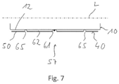
- FIG. 7 is a principal longitudinal sectional view of the muffler assembly unit along a plane VII-VII shown in FIGS. 4 to 6 .
- FIGS. 4-6 show in various section planes cross-sectional views of a muffler assembly unit 38 with a muffler 42 enclosed by a housing jacket 40 .
- the muffler 42 may be, in principle, configured as described above with reference to FIGS. 1-3 .
- the muffler 42 may thus have a muffler housing, which is generally designated by 10 , with a circumferential wall 12 formed, for example, by rolling a sheet metal body and with a front wall each at both axial ends of same.
- One or more intermediate walls, which form chambers communicating with one another or possibly also separated from one another, may be provided in the interior of the muffler housing 10 .
- Exhaust gas can be introduced into the muffler 42 via an exhaust gas pipe 44 protruding through the circumferential wall 12 , which exhaust gas pipe may form, for example, an inlet pipe.
- exhaust gas pipe 44 may form, for example, an inlet pipe.
- two or more exhaust gas pipes 44 forming such inlet pipes may be provided at a distance from one another in the direction of the housing longitudinal axis L of the muffler housing 10 , which housing longitudinal axis is at right angles to the drawing plane of FIG. 4 .
- the exhaust gas can be discharged to the surrounding area or into parts of an exhaust system following downstream via an exhaust gas pipe 46 traversing one of the front walls and, if present, one or more of the intermediate walls, which exhaust gas pipe may then form, for example, an outlet pipe.
- the housing jacket 40 encloses the muffler 10 in an entire circumferential area.
- the housing jacket 40 is configured with two jacket shells 48 , 50 . Where the two jacket shells 48 , 50 adjoin one another, these jacket shells 48 , 50 , which are provided as shaped sheet metal parts, are arranged adjoining one another with a connecting edge area 52 , 54 , which is, for example, bent outwards and, e.g., permanently connected to one another by crimping or/and welding.
- the jacket shells 48 , 50 are, in principle, adapted in their shape to the outer contour of the muffler housing 10 .
- the jacket shells 48 , 50 enclosing the muffler housing 10 in this area form a corresponding receiving opening 58 .
- a receiving bulge overlapping the muffler housing and receiving the housing bulge 56 thereof in this area could be formed in the housing jacket 40 .
- an exhaust gas pipe passage opening 60 allowing the passage of the exhaust gas pipe 44 , for example, adapted to the circumferential contour thereof, is provided in the housing jacket 40 in the area in which the two jacket shells 48 , 50 adjoin one another.
- the exhaust pipe 44 has a circular configuration, a semicircular part of this exhaust gas pipe passage opening 60 can be formed in each of the two jacket shells 48 , 50 .
- the housing jacket 40 may be configured, for example, such that the housing jacket 40 encloses the muffler housing 10 essentially only in the area of the circumferential wall 12 thereof, so that this muffler housing 10 is exposed outwards in the axial end areas, especially in the area of the front walls of the muffler housing 10 .
- the jacket shells 48 , 50 may, however, also be shaped such that they overlap this muffler housing at the axial end areas of the muffler housing 10 and thus also fully overlap the front walls.
- the connecting edge areas 52 , 54 in case of such a configuration are configured as essentially all-around edge areas, which are possibly only interrupted where an exhaust gas pipe passage opening or a receiving opening is formed.
- the housing jacket 40 is connected, e.g., by spot welding, to the muffler housing 10 , especially to the circumferential wall 12 at some connection areas 55 , 57 .
- the housing jacket 40 may be configured in some areas of the jacket shells 48 , 50 with base-like or arch-like bulges 59 , 61 , protruding inwards, i.e., in the direction towards the muffler housing 10 , which bulges are present on the outer surface of the muffler housing 10 and are connected in substance there to this muffler housing.
- a gap-like (gap) intermediate space 62 which generates an additional muffling effect, can thus be provided between the muffler housing 10 and the housing jacket 40 .
- This intermediate space 62 may be filled with a layer of insulating material 64 enclosing the muffler housing 10 on its outer side, which insulating material may lead to a further improvement of the muffling characteristic or/and to a thermal insulation.
- insulating material 64 enclosing the muffler housing 10 on its outer side, which insulating material may lead to a further improvement of the muffling characteristic or/and to a thermal insulation.
- Such fibrous or foam-like insulating material may be used here, as is also used in the interior of mufflers for lining chambers formed in same.
- such insulating material 64 is essentially provided only between the housing shell 48 and the muffler housing 10 , while the gap-like intermediate space 62 between the housing shell 50 and the muffler housing 10 is not filled with insulating material.
- the housing jacket 40 is fixed to the muffler housing 10 only in the area of the housing shell 50 in the connection areas 55 , 57 or by rib-like support areas 63 , 65 , which can be seen in FIG. 4 , supported on the outer side of the muffler housing 10 , but without being fixed there.
- a support of the housing jacket 40 in relation to the muffler housing may take place where an exhaust gas pipe passage opening is provided for guiding through an exhaust gas pipe or a receiving opening for receiving a bulge of the muffler housing 10 .
- insulating material 64 may, in addition or as an alternative, be provided in the area between the jacket shell 50 and the muffler housing 10 , or/and that, as an alternative or in addition, the jacket shell 48 may also be permanently connected to the muffler housing 10 or/and be supported in additional support areas in relation to this muffler housing 10 .
- connection areas 59 , 61 are preferably arranged in a connecting length area V, i.e., in the same length area in the direction of the housing longitudinal axis L, while the housing jacket 40 is not permanently connected to the muffler housing and thus can expand from this muffler housing 12 when heated, starting from this connecting length area V, in the direction towards the axial ends.
- the length area, in which the housing jacket 40 is fixed to the muffler housing 10 may be, for example, a longitudinal central area of the housing jacket 40 or of the muffler housing 10 , in order to provide sections of the housing jacket 40 of approximately the same length at both end areas, which sections are not fixed to the muffler housing 10 .
- an air guiding bulge 34 extending, for example, essentially over the entire axial length of the muffler housing 10 is formed in a circumferential area of the jacket shell 50 of the housing jacket 40 .
- the air guiding bulge 34 is integrated into the jacket shell 50 and provides in its circumferential expansion area an outer contour of the muffler assembly unit 38 , which outer contour deviates from the circumferential contour of the muffler housing 10 and provides a defined air guiding.
- the housing jacket 40 has a distance to the muffler housing 10 that is essentially uniform over the circumference in the areas 68 , 70 adjacent to the air guiding bulge 34 , except for the connection areas 55 , 57 or/and the support areas 63 , 65 , the distance of the jacket shell 50 from the muffler housing 10 , especially from the circumferential wall 12 of same, increases up to a maximum value M in the area of the air guiding bulge 34 , so that where, for example, the circumferential wall 12 has a circumferential contour curved with a greater radius of curvature, the air guiding opening 34 provides a circumferential contour that is approximately angular or is curved with a markedly smaller radius of curvature.
- the air guiding bulge 34 may, as this is shown in FIGS. 1-3 with reference to the state of the art, extend in the direction of the housing longitudinal axis L essentially along the entire circumferential wall 12 or of the entire muffler 42 .
- the air guiding bulge 34 could also be interrupted in the direction of the housing longitudinal axis, or/and a plurality of air guiding bulges following one another in the circumferential direction could be provided. Since the air guiding bulge 34 is integrated into the housing jacket 40 , this housing jacket 12 may be configured as closed in its axial end areas or at least in one axial end area, so that essentially a duct extending along the outer side of the muffler housing 10 and through which air can flow is not formed.
- Such a shape, for example, of the jacket shell 50 can be achieved by deep-drawing of a plate-like sheet metal blank in a correspondingly shaped deep-drawing mold and can also especially be provided if the housing jacket 40 overlaps the muffler 42 even at its axial end areas, i.e., in the area of its front walls.
- the duct formed by the provision of the air guiding bulge 34 could be produced by closing elements inserted into the air guiding bulge 34 and fixed, for example, by soldering or welding in axial end areas of the jacket shell 50 on the inner side.
- housing jacket 40 could have a one-piece configuration and, fully enclosing the circumferential wall of the muffler housing, have connecting edge areas that are positioned adjoining one another in a circumferential area and are to be connected to one another.
- the housing jacket 40 provides, furthermore, the possibility to introduce an additional thermal or/and acoustic insulation, and can especially expand uncoupled from the muffler itself in case of thermal load, so that there is no risk of a deformation or an excessive load in the areas, in which the formation provided for the defined guiding of air is fixed to the muffler housing 12 .
Abstract
Description
-
- a muffler with a muffler housing elongated along a housing longitudinal axis,
- a housing jacket enclosing the muffler housing, wherein at least one air guiding bulge is provided on the housing jacket.
Claims (18)
Applications Claiming Priority (2)
| Application Number | Priority Date | Filing Date | Title |
|---|---|---|---|
| DE102018101139.3 | 2018-01-19 | ||
| DE102018101139.3A DE102018101139A1 (en) | 2018-01-19 | 2018-01-19 | muffler assembly |
Publications (2)
| Publication Number | Publication Date |
|---|---|
| US20190226384A1 US20190226384A1 (en) | 2019-07-25 |
| US11242793B2 true US11242793B2 (en) | 2022-02-08 |
Family
ID=65023732
Family Applications (1)
| Application Number | Title | Priority Date | Filing Date |
|---|---|---|---|
| US16/249,258 Active 2040-03-15 US11242793B2 (en) | 2018-01-19 | 2019-01-16 | Muffler assembly unit |
Country Status (4)
| Country | Link |
|---|---|
| US (1) | US11242793B2 (en) |
| EP (1) | EP3514345B1 (en) |
| CN (1) | CN110056419B (en) |
| DE (1) | DE102018101139A1 (en) |
Families Citing this family (1)
| Publication number | Priority date | Publication date | Assignee | Title |
|---|---|---|---|---|
| FR3077094B1 (en) * | 2018-01-22 | 2021-01-08 | Renault Sas | DEVICE INCLUDING A SILENCER AND AN AERODYNAMIC DEFLECTOR |
Citations (18)
| Publication number | Priority date | Publication date | Assignee | Title |
|---|---|---|---|---|
| US4029167A (en) * | 1975-04-11 | 1977-06-14 | Massey-Ferguson Inc. | Exhaust system |
| US4265332A (en) * | 1979-06-21 | 1981-05-05 | Fmc Corporation | Heat extracting muffler system |
| US4609067A (en) | 1985-05-08 | 1986-09-02 | Maremont Corporation | Heat shield for a vehicular muffler |
| DE3625814A1 (en) | 1986-07-30 | 1988-02-18 | Bayerische Motoren Werke Ag | MOTOR VEHICLE, PARTICULARLY PERSONAL VEHICLES |
| US5183130A (en) | 1989-07-25 | 1993-02-02 | Honda Giken Kogyo Kabushiki Kaisha | Muffler device for motorcycle |
| US5482681A (en) | 1985-09-20 | 1996-01-09 | Tennessee Gas Pipeline Company | Catalytic converter for motor vehicles |
| WO2001031176A1 (en) | 1999-10-26 | 2001-05-03 | Timothy Simon Lyons | Vehicle exhaust assemblies |
| US6435272B1 (en) | 1998-12-31 | 2002-08-20 | Randy E. Voss | Exhaust cooling system vehicles |
| US20100176573A1 (en) * | 2008-12-31 | 2010-07-15 | Darrick Corneiius Melton | Muffler insulator for motorcycles |
| CN102191983A (en) | 2010-03-12 | 2011-09-21 | 王根良 | Automobile silencer |
| EP2573339A1 (en) | 2011-09-21 | 2013-03-27 | Honda Motor Co., Ltd. | Muffler system with protector for small-sized vehicle |
| CN203604012U (en) | 2013-11-19 | 2014-05-21 | 浙江吉利汽车研究院有限公司 | Automobile muffler |
| CN205225380U (en) | 2015-11-05 | 2016-05-11 | 陈培安 | Automobile silencer |
| US20160233739A1 (en) * | 2015-02-06 | 2016-08-11 | Champion Engine Technology, LLC | Electrical generator heat management system |
| DE102016113301A1 (en) | 2015-07-24 | 2017-01-26 | Ford Global Technologies, Llc | Silencer housing base with integral aerodynamic shielding |
| CN106917656A (en) | 2015-12-07 | 2017-07-04 | 埃贝斯佩歇废气技术合资公司 | Muffler and manufacture method |
| CN107060971A (en) | 2017-05-08 | 2017-08-18 | 浙江天泰机械有限公司 | Silencer and sound-attenuating system |
| CN107109980A (en) | 2015-03-24 | 2017-08-29 | 宝马股份公司 | The silencer of air gap isolation |
Family Cites Families (2)
| Publication number | Priority date | Publication date | Assignee | Title |
|---|---|---|---|---|
| CN2352680Y (en) * | 1998-07-23 | 1999-12-08 | 李国民 | Exhaust gases silencing apparatus for diesel engine |
| US9464557B2 (en) * | 2014-11-20 | 2016-10-11 | Ford Global Technologies, Llc | Muffler shield and muffler assembly employing the same |
-
2018
- 2018-01-19 DE DE102018101139.3A patent/DE102018101139A1/en active Pending
-
2019
- 2019-01-11 CN CN201910024917.8A patent/CN110056419B/en active Active
- 2019-01-14 EP EP19151538.6A patent/EP3514345B1/en active Active
- 2019-01-16 US US16/249,258 patent/US11242793B2/en active Active
Patent Citations (19)
| Publication number | Priority date | Publication date | Assignee | Title |
|---|---|---|---|---|
| US4029167A (en) * | 1975-04-11 | 1977-06-14 | Massey-Ferguson Inc. | Exhaust system |
| US4265332A (en) * | 1979-06-21 | 1981-05-05 | Fmc Corporation | Heat extracting muffler system |
| US4609067A (en) | 1985-05-08 | 1986-09-02 | Maremont Corporation | Heat shield for a vehicular muffler |
| US5482681A (en) | 1985-09-20 | 1996-01-09 | Tennessee Gas Pipeline Company | Catalytic converter for motor vehicles |
| DE3625814A1 (en) | 1986-07-30 | 1988-02-18 | Bayerische Motoren Werke Ag | MOTOR VEHICLE, PARTICULARLY PERSONAL VEHICLES |
| US5183130A (en) | 1989-07-25 | 1993-02-02 | Honda Giken Kogyo Kabushiki Kaisha | Muffler device for motorcycle |
| US6435272B1 (en) | 1998-12-31 | 2002-08-20 | Randy E. Voss | Exhaust cooling system vehicles |
| WO2001031176A1 (en) | 1999-10-26 | 2001-05-03 | Timothy Simon Lyons | Vehicle exhaust assemblies |
| US20100176573A1 (en) * | 2008-12-31 | 2010-07-15 | Darrick Corneiius Melton | Muffler insulator for motorcycles |
| CN102191983A (en) | 2010-03-12 | 2011-09-21 | 王根良 | Automobile silencer |
| EP2573339A1 (en) | 2011-09-21 | 2013-03-27 | Honda Motor Co., Ltd. | Muffler system with protector for small-sized vehicle |
| CN203604012U (en) | 2013-11-19 | 2014-05-21 | 浙江吉利汽车研究院有限公司 | Automobile muffler |
| US20160233739A1 (en) * | 2015-02-06 | 2016-08-11 | Champion Engine Technology, LLC | Electrical generator heat management system |
| CN107109980A (en) | 2015-03-24 | 2017-08-29 | 宝马股份公司 | The silencer of air gap isolation |
| DE102016113301A1 (en) | 2015-07-24 | 2017-01-26 | Ford Global Technologies, Llc | Silencer housing base with integral aerodynamic shielding |
| CN106368786A (en) | 2015-07-24 | 2017-02-01 | 福特环球技术公司 | Muffler shell body with integral aerodynamic shield |
| CN205225380U (en) | 2015-11-05 | 2016-05-11 | 陈培安 | Automobile silencer |
| CN106917656A (en) | 2015-12-07 | 2017-07-04 | 埃贝斯佩歇废气技术合资公司 | Muffler and manufacture method |
| CN107060971A (en) | 2017-05-08 | 2017-08-18 | 浙江天泰机械有限公司 | Silencer and sound-attenuating system |
Also Published As
| Publication number | Publication date |
|---|---|
| US20190226384A1 (en) | 2019-07-25 |
| EP3514345A1 (en) | 2019-07-24 |
| EP3514345B1 (en) | 2023-04-12 |
| CN110056419A (en) | 2019-07-26 |
| CN110056419B (en) | 2022-04-15 |
| DE102018101139A1 (en) | 2019-07-25 |
Similar Documents
| Publication | Publication Date | Title |
|---|---|---|
| US8292026B2 (en) | Silencer | |
| US6702062B2 (en) | Exhaust system for automobile engine | |
| EP0696677B1 (en) | An exhaust system for an engine | |
| US5581056A (en) | Muffler | |
| US4290501A (en) | Exhaust silencer, especially for small vehicles | |
| EP1775436B1 (en) | Exhaust system | |
| US3523590A (en) | Simplified muffler shell construction | |
| EP1091101B1 (en) | Exhaust pipe assembly of two-passage construction | |
| US9546581B2 (en) | Muffler for an exhaust system | |
| US5014510A (en) | Exhaust system, particularly for two-stroke cycle internal combustion engines | |
| US11242793B2 (en) | Muffler assembly unit | |
| RU2669074C1 (en) | System comprising heater and exhaust pipe with the built-in silencer and the method of its manufacture | |
| JP6757944B2 (en) | Engine exhaust silencer | |
| ES2644396T3 (en) | Exhaust manifold for an exhaust system of an internal combustion engine | |
| JPWO2006046375A1 (en) | Exhaust cylinder for exhaust system parts | |
| US8939254B2 (en) | Muffler unit | |
| EP3623598B1 (en) | Turbine housing | |
| US11377990B2 (en) | Exhaust pipe | |
| US20230024144A1 (en) | Muffler | |
| JPH0742547A (en) | Double pipe for exhaust system for vehicle | |
| US9689302B2 (en) | Exhaust manifold | |
| JP2006336587A (en) | Flexible tube for exhaust system of automobile | |
| US11181031B2 (en) | Muffler | |
| JP7364549B2 (en) | Exhaust pipe | |
| US20180230889A1 (en) | Inlet Device for a Catalytic Converter |
Legal Events
| Date | Code | Title | Description |
|---|---|---|---|
| FEPP | Fee payment procedure |
Free format text: ENTITY STATUS SET TO UNDISCOUNTED (ORIGINAL EVENT CODE: BIG.); ENTITY STATUS OF PATENT OWNER: LARGE ENTITY |
|
| STPP | Information on status: patent application and granting procedure in general |
Free format text: NON FINAL ACTION MAILED |
|
| STPP | Information on status: patent application and granting procedure in general |
Free format text: RESPONSE TO NON-FINAL OFFICE ACTION ENTERED AND FORWARDED TO EXAMINER |
|
| STPP | Information on status: patent application and granting procedure in general |
Free format text: FINAL REJECTION MAILED |
|
| AS | Assignment |
Owner name: PUREM GMBH, FORMERLY, EBERSPAECHER EXHAUST TECHNOLOGY GMBH, GERMANY Free format text: CHANGE OF NAME;ASSIGNOR:EBERSPAECHER EXHAUST TECHNOLOGY GMBH & CO. KG;REEL/FRAME:056969/0564 Effective date: 20210615 |
|
| STPP | Information on status: patent application and granting procedure in general |
Free format text: DOCKETED NEW CASE - READY FOR EXAMINATION |
|
| STPP | Information on status: patent application and granting procedure in general |
Free format text: NOTICE OF ALLOWANCE MAILED -- APPLICATION RECEIVED IN OFFICE OF PUBLICATIONS |
|
| STPP | Information on status: patent application and granting procedure in general |
Free format text: PUBLICATIONS -- ISSUE FEE PAYMENT VERIFIED |
|
| STCF | Information on status: patent grant |
Free format text: PATENTED CASE |