US11241807B2 - Molded article and manufacturing method for same - Google Patents
Molded article and manufacturing method for same Download PDFInfo
- Publication number
- US11241807B2 US11241807B2 US16/337,311 US201716337311A US11241807B2 US 11241807 B2 US11241807 B2 US 11241807B2 US 201716337311 A US201716337311 A US 201716337311A US 11241807 B2 US11241807 B2 US 11241807B2
- Authority
- US
- United States
- Prior art keywords
- molded article
- disposed
- duct
- rib
- tubular
- Prior art date
- Legal status (The legal status is an assumption and is not a legal conclusion. Google has not performed a legal analysis and makes no representation as to the accuracy of the status listed.)
- Active, expires
Links
Images


Classifications
-
- B—PERFORMING OPERATIONS; TRANSPORTING
- B29—WORKING OF PLASTICS; WORKING OF SUBSTANCES IN A PLASTIC STATE IN GENERAL
- B29C—SHAPING OR JOINING OF PLASTICS; SHAPING OF MATERIAL IN A PLASTIC STATE, NOT OTHERWISE PROVIDED FOR; AFTER-TREATMENT OF THE SHAPED PRODUCTS, e.g. REPAIRING
- B29C49/00—Blow-moulding, i.e. blowing a preform or parison to a desired shape within a mould; Apparatus therefor
- B29C49/42—Component parts, details or accessories; Auxiliary operations
- B29C49/4273—Auxiliary operations after the blow-moulding operation not otherwise provided for
-
- B—PERFORMING OPERATIONS; TRANSPORTING
- B29—WORKING OF PLASTICS; WORKING OF SUBSTANCES IN A PLASTIC STATE IN GENERAL
- B29D—PRODUCING PARTICULAR ARTICLES FROM PLASTICS OR FROM SUBSTANCES IN A PLASTIC STATE
- B29D23/00—Producing tubular articles
- B29D23/001—Pipes; Pipe joints
-
- B—PERFORMING OPERATIONS; TRANSPORTING
- B26—HAND CUTTING TOOLS; CUTTING; SEVERING
- B26F—PERFORATING; PUNCHING; CUTTING-OUT; STAMPING-OUT; SEVERING BY MEANS OTHER THAN CUTTING
- B26F1/00—Perforating; Punching; Cutting-out; Stamping-out; Apparatus therefor
- B26F1/0015—Perforating; Punching; Cutting-out; Stamping-out; Apparatus therefor specially adapted for perforating tubes
- B26F1/0053—Perforating; Punching; Cutting-out; Stamping-out; Apparatus therefor specially adapted for perforating tubes by machining, e.g. cutting, grinding, projections on the tube wall
-
- B—PERFORMING OPERATIONS; TRANSPORTING
- B29—WORKING OF PLASTICS; WORKING OF SUBSTANCES IN A PLASTIC STATE IN GENERAL
- B29C—SHAPING OR JOINING OF PLASTICS; SHAPING OF MATERIAL IN A PLASTIC STATE, NOT OTHERWISE PROVIDED FOR; AFTER-TREATMENT OF THE SHAPED PRODUCTS, e.g. REPAIRING
- B29C44/00—Shaping by internal pressure generated in the material, e.g. swelling or foaming ; Producing porous or cellular expanded plastics articles
- B29C44/02—Shaping by internal pressure generated in the material, e.g. swelling or foaming ; Producing porous or cellular expanded plastics articles for articles of definite length, i.e. discrete articles
-
- B—PERFORMING OPERATIONS; TRANSPORTING
- B29—WORKING OF PLASTICS; WORKING OF SUBSTANCES IN A PLASTIC STATE IN GENERAL
- B29C—SHAPING OR JOINING OF PLASTICS; SHAPING OF MATERIAL IN A PLASTIC STATE, NOT OTHERWISE PROVIDED FOR; AFTER-TREATMENT OF THE SHAPED PRODUCTS, e.g. REPAIRING
- B29C44/00—Shaping by internal pressure generated in the material, e.g. swelling or foaming ; Producing porous or cellular expanded plastics articles
- B29C44/34—Auxiliary operations
- B29C44/56—After-treatment of articles, e.g. for altering the shape
-
- B—PERFORMING OPERATIONS; TRANSPORTING
- B29—WORKING OF PLASTICS; WORKING OF SUBSTANCES IN A PLASTIC STATE IN GENERAL
- B29C—SHAPING OR JOINING OF PLASTICS; SHAPING OF MATERIAL IN A PLASTIC STATE, NOT OTHERWISE PROVIDED FOR; AFTER-TREATMENT OF THE SHAPED PRODUCTS, e.g. REPAIRING
- B29C49/00—Blow-moulding, i.e. blowing a preform or parison to a desired shape within a mould; Apparatus therefor
- B29C49/02—Combined blow-moulding and manufacture of the preform or the parison
- B29C49/04—Extrusion blow-moulding
- B29C49/0411—Means for defining the wall or layer thickness
- B29C49/04112—Means for defining the wall or layer thickness for varying the thickness
-
- B—PERFORMING OPERATIONS; TRANSPORTING
- B29—WORKING OF PLASTICS; WORKING OF SUBSTANCES IN A PLASTIC STATE IN GENERAL
- B29C—SHAPING OR JOINING OF PLASTICS; SHAPING OF MATERIAL IN A PLASTIC STATE, NOT OTHERWISE PROVIDED FOR; AFTER-TREATMENT OF THE SHAPED PRODUCTS, e.g. REPAIRING
- B29C49/00—Blow-moulding, i.e. blowing a preform or parison to a desired shape within a mould; Apparatus therefor
- B29C49/42—Component parts, details or accessories; Auxiliary operations
- B29C49/42394—Providing specific wall thickness
-
- B—PERFORMING OPERATIONS; TRANSPORTING
- B29—WORKING OF PLASTICS; WORKING OF SUBSTANCES IN A PLASTIC STATE IN GENERAL
- B29C—SHAPING OR JOINING OF PLASTICS; SHAPING OF MATERIAL IN A PLASTIC STATE, NOT OTHERWISE PROVIDED FOR; AFTER-TREATMENT OF THE SHAPED PRODUCTS, e.g. REPAIRING
- B29C49/00—Blow-moulding, i.e. blowing a preform or parison to a desired shape within a mould; Apparatus therefor
- B29C49/42—Component parts, details or accessories; Auxiliary operations
- B29C49/4273—Auxiliary operations after the blow-moulding operation not otherwise provided for
- B29C49/4278—Cutting
-
- B—PERFORMING OPERATIONS; TRANSPORTING
- B60—VEHICLES IN GENERAL
- B60H—ARRANGEMENTS OF HEATING, COOLING, VENTILATING OR OTHER AIR-TREATING DEVICES SPECIALLY ADAPTED FOR PASSENGER OR GOODS SPACES OF VEHICLES
- B60H1/00—Heating, cooling or ventilating devices
- B60H1/00507—Details, e.g. mounting arrangements, desaeration devices
- B60H1/00557—Details of ducts or cables
- B60H1/00564—Details of ducts or cables of air ducts
-
- B—PERFORMING OPERATIONS; TRANSPORTING
- B29—WORKING OF PLASTICS; WORKING OF SUBSTANCES IN A PLASTIC STATE IN GENERAL
- B29C—SHAPING OR JOINING OF PLASTICS; SHAPING OF MATERIAL IN A PLASTIC STATE, NOT OTHERWISE PROVIDED FOR; AFTER-TREATMENT OF THE SHAPED PRODUCTS, e.g. REPAIRING
- B29C2793/00—Shaping techniques involving a cutting or machining operation
- B29C2793/0009—Cutting out
- B29C2793/0018—Cutting out for making a hole
-
- B—PERFORMING OPERATIONS; TRANSPORTING
- B29—WORKING OF PLASTICS; WORKING OF SUBSTANCES IN A PLASTIC STATE IN GENERAL
- B29C—SHAPING OR JOINING OF PLASTICS; SHAPING OF MATERIAL IN A PLASTIC STATE, NOT OTHERWISE PROVIDED FOR; AFTER-TREATMENT OF THE SHAPED PRODUCTS, e.g. REPAIRING
- B29C48/00—Extrusion moulding, i.e. expressing the moulding material through a die or nozzle which imparts the desired form; Apparatus therefor
- B29C48/001—Combinations of extrusion moulding with other shaping operations
- B29C48/0017—Combinations of extrusion moulding with other shaping operations combined with blow-moulding or thermoforming
-
- B—PERFORMING OPERATIONS; TRANSPORTING
- B29—WORKING OF PLASTICS; WORKING OF SUBSTANCES IN A PLASTIC STATE IN GENERAL
- B29C—SHAPING OR JOINING OF PLASTICS; SHAPING OF MATERIAL IN A PLASTIC STATE, NOT OTHERWISE PROVIDED FOR; AFTER-TREATMENT OF THE SHAPED PRODUCTS, e.g. REPAIRING
- B29C48/00—Extrusion moulding, i.e. expressing the moulding material through a die or nozzle which imparts the desired form; Apparatus therefor
- B29C48/03—Extrusion moulding, i.e. expressing the moulding material through a die or nozzle which imparts the desired form; Apparatus therefor characterised by the shape of the extruded material at extrusion
- B29C48/09—Articles with cross-sections having partially or fully enclosed cavities, e.g. pipes or channels
-
- B—PERFORMING OPERATIONS; TRANSPORTING
- B29—WORKING OF PLASTICS; WORKING OF SUBSTANCES IN A PLASTIC STATE IN GENERAL
- B29C—SHAPING OR JOINING OF PLASTICS; SHAPING OF MATERIAL IN A PLASTIC STATE, NOT OTHERWISE PROVIDED FOR; AFTER-TREATMENT OF THE SHAPED PRODUCTS, e.g. REPAIRING
- B29C48/00—Extrusion moulding, i.e. expressing the moulding material through a die or nozzle which imparts the desired form; Apparatus therefor
- B29C48/25—Component parts, details or accessories; Auxiliary operations
- B29C48/36—Means for plasticising or homogenising the moulding material or forcing it through the nozzle or die
- B29C48/375—Plasticisers, homogenisers or feeders comprising two or more stages
- B29C48/388—Plasticisers, homogenisers or feeders comprising two or more stages using a screw extruder and a ram or piston
-
- B—PERFORMING OPERATIONS; TRANSPORTING
- B29—WORKING OF PLASTICS; WORKING OF SUBSTANCES IN A PLASTIC STATE IN GENERAL
- B29C—SHAPING OR JOINING OF PLASTICS; SHAPING OF MATERIAL IN A PLASTIC STATE, NOT OTHERWISE PROVIDED FOR; AFTER-TREATMENT OF THE SHAPED PRODUCTS, e.g. REPAIRING
- B29C49/00—Blow-moulding, i.e. blowing a preform or parison to a desired shape within a mould; Apparatus therefor
- B29C49/02—Combined blow-moulding and manufacture of the preform or the parison
- B29C49/04—Extrusion blow-moulding
-
- B—PERFORMING OPERATIONS; TRANSPORTING
- B29—WORKING OF PLASTICS; WORKING OF SUBSTANCES IN A PLASTIC STATE IN GENERAL
- B29K—INDEXING SCHEME ASSOCIATED WITH SUBCLASSES B29B, B29C OR B29D, RELATING TO MOULDING MATERIALS OR TO MATERIALS FOR MOULDS, REINFORCEMENTS, FILLERS OR PREFORMED PARTS, e.g. INSERTS
- B29K2105/00—Condition, form or state of moulded material or of the material to be shaped
- B29K2105/04—Condition, form or state of moulded material or of the material to be shaped cellular or porous
-
- B—PERFORMING OPERATIONS; TRANSPORTING
- B29—WORKING OF PLASTICS; WORKING OF SUBSTANCES IN A PLASTIC STATE IN GENERAL
- B29L—INDEXING SCHEME ASSOCIATED WITH SUBCLASS B29C, RELATING TO PARTICULAR ARTICLES
- B29L2023/00—Tubular articles
-
- B—PERFORMING OPERATIONS; TRANSPORTING
- B29—WORKING OF PLASTICS; WORKING OF SUBSTANCES IN A PLASTIC STATE IN GENERAL
- B29L—INDEXING SCHEME ASSOCIATED WITH SUBCLASS B29C, RELATING TO PARTICULAR ARTICLES
- B29L2023/00—Tubular articles
- B29L2023/22—Tubes or pipes, i.e. rigid
Definitions
- the present application relates to a molded article and a manufacturing method for the same.
- a tube-shaped air-conditioning duct for circulating air is used.
- the opening portion is formed by forming a part called a disposal bag which is constituted by providing a closure portion at one end of a tubular portion, and cutting to remove the closure portion.
- a disposal bag which is constituted by providing a closure portion at one end of a tubular portion, and cutting to remove the closure portion.
- residual stress is present in the tubular portion constituting the disposal bag, and the balance of the residual stress is maintained in a state in which the closure portion is provided, so that the shape of the disposal bag is maintained. Therefore, if the closure portion is cut off (removed by cutting), sometimes, the opening portion may be deformed in a narrowed manner, or the cut end of the tubular portion may be deformed in a direction perpendicular to the opening surface, due to the fact that the balance of the residual stress is broken. If the opening portion is deformed, problems such as poor joining with other members may occur.
- the present application has been made in view of such circumstances, and provides a molded article capable of suppressing deformation of an opening portion.
- a molded article comprising a tubular base portion and an opening portion disposed in the base portion, wherein a rib is disposed at a position adjacent to the opening portion.
- a rib is disposed at a position adjacent to a peripheral edge of the opening portion, and the peripheral edge is reinforced by the rib, therefore deformation of the opening portion is suppressed.
- the rib is disposed between a parting line of the molded article and the opening portion.
- a distance between the parting line of the molded article and the opening portion is set to be L1 and a length of a side wall of the rib is set to be L2, L2/L1 is 0.5 or more.
- the side wall of the rib is disposed to be connected to the parting line.
- the rib is disposed such that its depth increases as it extends away from the opening portion.
- the molded article comprises a beam rib disposed along a peripheral edge of the opening portion, and the beam rib is disposed between the parting line of the molded article and the opening portion.
- the rib is disposed to be connected to the beam rib.
- a plurality of the ribs are disposed to be connected to the beam rib.
- the beam rib is constituted by a groove-shaped concave portion disposed along the peripheral edge.
- the rib is disposed within the groove-shaped concave portion.
- a peripheral edge of the opening portion has a pair of long-side portions opposite to each other and a pair of short-side portions disposed to be connected to the pair of long-side portions.
- the rib is disposed at a center of the long-side portion.
- the molded article is a foamed molded article.
- a method of manufacturing a molded article comprising a molded body formation step and a cut-off step, wherein in the molded body formation step, a molded body is formed by molding a molten resin, wherein the molded body comprises a tubular base portion, a tubular portion disposed to be erected from the base portion, and a rib located at a position adjacent to the tubular portion, a closure portion is disposed at one end of the tubular portion, and in the cut-off step, the closure portion is removed by cutting the tubular portion to form an opening portion.
- a method of manufacturing a molded article comprising: a molded body formation step of forming a molded body by molding a molten resin, the molded body having a tubular portion which has one end provided with a closure portion; and a cut-off step of cutting off the closure portion by cutting the tubular portion, wherein in the cut-off step, the cutting is performed in a state in which a side wall of the tubular portion, in a plane, is warped by an external force.
- the closure portion is cut off without warping the side wall of the tubular portion in a plane, there is a case where a force enabling the side wall of the tubular portion to be warped in a plane is applied to the side wall of the tubular portion due to residual stress which is present on the side wall of the tubular portion due to the cross-sectional shape of the tubular portion.
- a force enabling the side wall of the tubular portion to be warped in a plane is applied to the side wall of the tubular portion due to residual stress which is present on the side wall of the tubular portion due to the cross-sectional shape of the tubular portion.
- the side wall of the tubular portion, in a plane is warped by an external force, a restoring force in the in-plane direction is generated on the side wall of the tubular portion.
- the closure portion is cut off in a state in which the side wall of the tubular portion, in a plane, is warped by an external force so as to generate a restoring force counteracting the residual stress, the residual stress and the restoring force counteract each other such that the deformation of the cut end of the tubular portion is suppressed.
- the side wall of the tubular portion has a cross-sectional shape including a pair of corner portions, and in the cut-off step, the side wall of the tubular portion is warped in a plane in such a manner that a center of the pair of corner portions is made to face a direction away from the closure portion.
- the side wall of the tubular portion has a pair of long-side portions opposite to each other and a pair of short-side portions disposed to be connected with the pair of long-side portions, and in the cut-off step, the long-side portion is warped in the plane in such a manner that a center of the long-side portion is made to face a direction away from the closure portion.
- the molded body comprises a base portion, and the tubular portion is disposed in such a manner as to be erected from the base portion.
- the base portion has a peripheral edge portion disposed at a peripheral edge of the tubular portion and an adjacent wall disposed adjacent to the peripheral edge portion, wherein the adjacent wall has an angle of 75 degrees or less with respect to the peripheral edge portion.
- the side wall of the tubular portion, in a plane is warped by pressing the base portion.
- the base portion has a peripheral edge portion provided at a peripheral edge of the tubular portion, the peripheral edge portion is bent so as to bulge in a direction in which the tubular portion is erected, and in the cut-off step, the side wall of the tubular portion, in a plane, is warped by pressing the peripheral edge portion.
- the cut-off step includes a step of disposing the molded body in a cutting jig and cutting off the closure portion in this state, wherein the cutting jig has a jig opening portion capable of accommodating the tubular portion, the molded body is disposed such that the tubular portion is accommodated in the jig opening portion and the peripheral edge portion abuts against the cutting jig, and the closure portion is removed by cutting, in a state in which the peripheral edge portion is deformed by being pressed against the cutting jig.
- the molded body is cut linearly.
- the molded body is formed by blow molding.
- the molten resin contains a foaming agent, and the molded body is a foamed molded body.
- FIG. 1 is an example of a molding machine 1 that can be used in a manufacturing method according to an embodiment of the present application.
- FIG. 2 is a perspective view showing a molded body 10 used for manufacturing a molded article 5 of a first embodiment of the present application.
- FIG. 3 shows a molded article 5 obtained by removing closure portions 3 a and 4 a from the molded body 10 of FIG. 2 .
- FIG. 4 is a sectional perspective view taken through the center of a rib 9 of the molded article 5 of FIG. 3 .
- FIG. 5 is a sectional view in which the vicinity of the section in the sectional perspective view of FIG. 4 is enlarged.
- FIG. 6 is a perspective view showing a molded body 10 used for manufacturing a molded article 5 of a second embodiment of the present application.
- FIG. 7 shows a molded article 5 obtained by removing the closure portions 3 a and 4 a from the molded body 10 of FIG. 6 .
- FIG. 8 is a sectional perspective view taken through the center of the molded article 5 of FIG. 7 .
- FIG. 9 is a sectional view in which the vicinity of the section in the sectional perspective view of FIG. 4 is enlarged.
- FIG. 10 shows a molded body 110 for manufacturing an air-conditioning duct
- (a) in FIG. 10 is a plan view when viewed from the side where a tubular portion 104 is located, and (b) in FIG. 10 is a right side view.
- FIG. 11 is an enlarged view of a region A in (a) of FIG. 10
- (b) in FIG. 11 is an enlarged view of a region B in (b) of FIG. 10 .
- FIG. 12 shows a molded article 105 obtained by removing closure portions 103 a and 104 a from the molded body 110 of FIG. 10 , (a) in FIG. 12 is a plan view when viewed from the side where the tubular portion 104 is located, and (b) in FIG. 12 is a right side view.
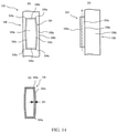
- FIG. 13 is an enlarged view of a region A in (a) of FIG. 12
- (b) in FIG. 13 is an enlarged view of a region B in (b) of FIG. 12 .
- FIG. 14 shows a molded body 110 in a state in which a long-side portion 104 c is bent in a direction in which the center of the long-side portion 104 c of the tubular portion 104 is away from an opening portion 104 b
- (a) and (b) in FIG. 14 are enlarged views of parts respectively corresponding to the region A of (a) in FIG. 10 and the region B of (b) in FIG. 10
- (c) in FIG. 14 is an end view along a cutting line S in (b) of FIG. 14 .
- FIG. 15 shows a molded article 105 obtained by removing a closure portion 104 a from the molded body 110 of FIG. 14
- (a) and (b) in FIG. 15 are enlarged views of parts corresponding to the region A of (a) in FIG. 11 and the region B of (b) in FIG. 11 , respectively.
- FIG. 16 shows a molded body 110 formed such that a closure portion 104 a and a peripheral edge portion 106 a are bent to bulge in a direction in which the tubular portion 104 is erected
- (a) and (b) in FIG. 16 are enlarged views of parts respectively corresponding to the region A of (a) in FIG. 10 and the region B of (b) in FIG. 10
- (c) in FIG. 16 is a G-G sectional view of (a) in FIG. 16 .
- FIG. 17 shows a molded article 105 obtained by removing the closure portion 104 a from the molded body 110 of FIG. 16
- (a) and (b) in FIG. 17 are enlarged views of parts corresponding to the region A of (a) in FIG. 11 and the region B of (b) in FIG. 11 , respectively.
- FIG. 18 are right side views showing a step of pressing the peripheral edge portion 106 a by an external force F and cutting the tubular portion 104 .
- FIG. 19 is a plan view of a cutting jig 107 .
- FIG. 20 shows a state in which the molded body 110 is disposed on the cutting jig 107 , and (a) and (b) in FIG. 20 are sectional views corresponding to the X-X section and the Y-Y section in FIG. 19 , respectively.
- FIG. 21 shows a state in which the peripheral edge portion 106 a is pressed to abut against the cutting jig 107 by an external force F from the state of FIG. 20
- (a) and (b) in FIG. 21 are sectional views corresponding to the X-X section and the Y-Y section in FIG. 19 , respectively.
- FIG. 22 are right side views showing a molded body 110 , with the molded body 110 being formed such that the closure portion 104 a is flat and the peripheral edge portion 106 a is bent to bulge in the direction in which the tubular portion 104 is erected, (a) in FIG. 22 shows a state before an external force F is applied, and (b) in FIG. 22 shows a state in which the external force F is applied to the peripheral edge portion 106 a.
- FIG. 23 are right side views showing a molded body 110 , with the molded body 110 being formed such that the closure portion 104 a and the peripheral edge portion 106 a are bent to bulge in the direction in which the tubular portion 104 is erected, (a) in FIG. 23 shows a state before an external force F is applied, and (b) in FIG. 23 shows a state in which the external force F is applied to the closure portion 106 a.
- FIG. 24 are right side views showing a molded body 110 , with the molded body 110 being formed such that the closure portion 104 a and the peripheral edge portion 106 a are bent to bulge in the direction in which the tubular portion 104 is erected, (a) in FIG. 24 shows a state before an external force F is applied, and (b) in FIG. 24 shows a state in which the external force F is applied in such a manner that the entire molded body 110 is bent.
- FIG. 25 is a C-C sectional view of (a) in FIG. 18
- (b) in FIG. 25 is a D-D sectional view of (c) in FIG. 18 .
- FIG. 26 respectively show a molded body 110 and a molded article 105 in which an adjacent wall 106 b has an angle of 75 degrees or less with respect to the peripheral edge portion 106 a
- FIG. 26 are sectional views corresponding to (a) and (b) in FIG. 25 , respectively.
- FIG. 27 is a sectional view corresponding to (b) in FIG. 25 , showing a molded article 105 formed by cutting off the entire tubular portion 104 .
- FIG. 28 is a schematic plan view showing a state before ducts are connected.
- FIG. 29 is a schematic plan view showing a state after the ducts are connected.
- FIG. 30 is a schematic plan view for illustrating a position at which the duct is to be cut.
- FIG. 31 is a schematic plan view in a case where the direction of a positioning mark coincides with an insertion direction.
- FIG. 32 is a schematic plan view showing another example of the positioning mark, (A) in FIG. 32 shows a view prior to insertion, and (B) in FIG. 32 shows a view after insertion.
- FIG. 33 is a view showing a state in which the positioning marks are formed on both front and back surfaces, (A) in FIG. 33 is a schematic plan view of the front surface, and (B) in FIG. 33 is a schematic plan view of the back surface.
- FIG. 34 is a schematic perspective view showing an example of a foamed duct.
- FIG. 35 is a view showing an example of a cross-sectional shape of a foamed duct.
- FIG. 36 is a view showing the vicinity of a parting line of the foamed duct of FIG. 34 in an enlarged manner.
- FIG. 37 is a view for illustrating a cross-sectional shape of the foamed duct shown in FIGS. 34 and 35 .
- FIG. 38 is a view schematically showing another example of the cross-sectional shape of the foamed duct.
- FIG. 39 is a view showing an example of a metal mold for molding a foamed duct.
- FIG. 40 shows a process of forming a cross-sectional shape of a prior foamed duct
- A in FIG. 40 is a view showing a state in which a parison is supplied
- B in FIG. 40 is a view showing a state in which mold closing is started
- C in FIG. 40 is a view showing a state in which the mold is closed
- D in FIG. 40 is a view showing a cross-sectional shape of a foamed duct in which a thicker portion is formed.
- FIG. 41 shows another example of a cross-sectional shape of a prior foamed duct, and is a view showing a cross-sectional shape of a foamed duct having an inner surface provided with a groove portion.
- the molding machine 1 has a resin supply device 2 , a head 18 , and split molds 19 .
- the resin supply device 2 has a hopper 12 , an extruder 13 , an injector 16 , and an accumulator 17 .
- the extruder 13 and the accumulator 17 are connected via a connecting pipe 25 .
- the accumulator 17 and the head 18 are connected via a connecting pipe 27 .
- each structure will be described in detail.
- the hopper 12 is used for introducing a raw material resin 11 into a cylinder 13 a of the extruder 13 .
- the form of the raw material resin 11 is not particularly limited, but is usually pellet-shaped.
- the raw material resin 11 is, for example, a thermoplastic resin such as polyolefin, and examples of the polyolefin may include low-density polyethylene, linear low-density polyethylene, high-density polyethylene, polypropylene, an ethylene-propylene copolymer, a mixture thereof, and so on.
- the screw which is arranged in the cylinder 13 a is rotated to simultaneously mix and convey the molten resin.
- a gear device is disposed at a base end of the screw, and the screw is rotationally driven by the gear device.
- the number of the screws arranged in the cylinder 13 a may be one, or may also be two or more.
- An injector 16 for injecting a foaming agent into the cylinder 13 a is disposed in the cylinder 13 a .
- the injector 16 can be omitted.
- the foaming agent injected from the injector 16 may include a physical foaming agent, a chemical foaming agent, and a mixture thereof, but a physical foaming agent is preferred.
- a physical foaming agent an inorganic physical foaming agent such as air, carbon dioxide gas, nitrogen gas, water, etc. and an organic physical foaming agent such as butane, pentane, hexane, dichloromethane, dichloroethane, etc. and further a supercritical fluid thereof may be used.
- the supercritical fluid is preferably produced by using carbon dioxide, nitrogen or the like.
- the supercritical fluid is obtained at a critical temperature of ⁇ 149.1° C. and at a critical pressure of 3.4 MPa or more
- the supercritical fluid is obtained at a critical temperature of 31° C. and at a critical pressure of 7.4 MPa or more.
- the chemical foaming agent may include a chemical foaming agent which generates carbon dioxide gas by a chemical reaction between an acid (e.g., citric acid or salt thereof) and an alkali (e.g., sodium bicarbonate).
- the chemical foaming agent may also be introduced from the hopper 12 , instead of being injected from the injector 16 .
- the molten resin 11 a to which the foaming agent is added or the foaming agent is not added, is extruded from a resin extrusion port of the cylinder 13 a and injected into the accumulator 17 through the connecting pipe 25 .
- the accumulator 17 has a cylinder 17 a and a piston 17 b slidable inside the cylinder 17 a , wherein the molten resin 11 a can be stored in the cylinder 17 a .
- the piston 17 b is moved so that the molten resin 11 a is extruded out and hung down, through the connecting pipe 27 , from a die slit disposed in the head 18 so as to form a parison 23 .
- the shape of the parison 23 is not specifically limited, and may be a cylindrical shape, or may be a sheet shape.
- the parison 23 is guided between a pair of split molds 19 .
- the molding of the parison 23 is performed using the split molds 19 , whereby a molded body 10 as shown in FIG. 2 is obtained.
- the molding method in which the split mold 19 is used is not particularly limited, and may be blow molding in which molding is performed by blowing air into a cavity defined by the split molds 19 , or may be vacuum molding in which the molding of the parison 23 is performed by reducing the pressure in the cavity from an inner surface of the cavity of the split molds 19 , or may be a combination thereof.
- the parison 23 becomes a foamed parison
- the molded body 10 becomes a foamed molded body.
- FIG. 2 shows a molded body 10 for manufacturing an air-conditioning duct.
- the molded body 10 has tubular portions 3 and 4 having one ends provided with closure portions 3 a and 4 a respectively.
- the tubular portion 4 is disposed to be erected from a tubular base portion 6 .
- the tubular portions 3 are disposed at two ends of the base portion 6 .
- the molded body 10 does not have a branched structure, but the tubular portion 3 may be branched so that the number of the tubular portions 3 is three, four, or more.
- FIGS. 1 to 6 A molded article of the first embodiment of the present application and a method of manufacturing the same will be described by using FIGS. 1 to 6 .
- the method of the present embodiment comprises a molded body formation step and a cut-off step. The details will be described below.
- a molded body 10 is formed by molding a molten resin 11 a , wherein the molded body 10 comprises tubular portions 3 and 4 having one ends provided with closure portions 3 a and 4 a respectively.
- This step can be carried out using the molding machine 1 described above.
- the effect of the present application can be obtained no matter whether the molded body 10 is a solid molded article or a foamed molded article. But when the molded body 10 is a foamed molded article, the shapes of opening portions 3 b and 4 b will be remarkably changed by removing the closure portions 3 a and 4 a through cutting, therefore use of the present application is of particularly great technical significance when the molded body 10 is a foamed molded article.
- the expansion ratio of the foamed molded article is, for example, 1.5 to 5, preferably 2 to 4, and specifically, for example, 1.5, 2, 2.5, 3, 3.5, 4, 4.5, or 5, or may be within a range between any two of the numerical values exemplified herein.
- the thickness of the foamed molded article is, for example, 1 to 7 mm, preferably 1.5 to 5 mm, and specifically, for example, 1, 1.5, 2, 2.5, 3, 3.5, 4, 4.5, 5, 5.5, 6, 6.5, or 7 mm, or may be within a range between any two of the numerical values exemplified herein.
- closure portions 3 a and 4 a are removed by cutting the tubular portions 3 and 4 along cutting lines S indicated by dot-and-dash lines.
- opening portions 3 b and 4 b are formed in the tubular portions 3 and 4 to obtain a molded article 5 .
- the tubular portion 4 and the opening portion 4 b are in a rectangular shape. Therefore, the side wall of the tubular portion 4 and the peripheral edge of the opening portion 4 b have a pair of long-side portions 4 c opposite to each other and a pair of short-side portions 4 d disposed to be connected with the pair of long-side portions 4 c .
- the long-side portion 4 c and the short-side portion 4 d are connected at a corner portion 4 e .
- the length of the long-side portion 4 c is, for example, 100 to 500 mm, and specifically, for example, 100, 150, 200, 250, 300, 350, 400, 450, or 500 mm, or may be within a range between any two of the numerical values exemplified herein.
- the length of the short-side portion 4 d is, for example, 50 to 250 mm, and specifically, for example, 50, 100, 150, 200, or 250 mm, or may be within a range between any two of the numerical values exemplified herein.
- the ratio of the length of the long-side portion 4 c to the length of the short-side portion 4 d is, for example, 1.5-5, and specifically, for example, 1.5, 2, 2.5, 3, 3.5, 4, 4.5, or 5 mm, or may be within a range between any two of the numerical values exemplified herein.
- the radius of curvature of the corner portion 4 e is, for example, 1 to 30 mm, and specifically, for example, 1, 5, 10, 15, 20, 25, or 30 mm, or may be within a range between any two of the numerical values exemplified herein.
- the tubular portion 4 is disposed to be erected from the base portion 6 .
- the height of the tubular portion 4 is, for example, 10 to 50 mm, and specifically, for example, 10, 15, 20, 25, 30, 35, 40, 45, or 50 mm, or may be within a range between any two of the numerical values exemplified herein.
- the base portion 6 is in a tubular shape.
- the base portion 6 has a base wall 6 a , side walls 6 b and 6 c , and an opposite wall 6 d .
- the tubular portion 4 and the opening portion 4 b are formed on the base wall 6 a .
- the side walls 6 b and 6 c are substantially parallel to each other.
- the opening portion 4 b is disposed between the side walls 6 b and 6 c .
- the opposite wall 6 d is opposite to the opening portion 4 b .
- the side walls 6 b and 6 c are connected by the opposite wall 6 d . As shown in FIG.
- an angle ⁇ between an opening surface (a surface formed by the peripheral edge of the opening portion 4 b ) P and the side wall 6 b is preferably 20 to 80 degrees, preferably 30 to 60 degrees, and preferably 40 to 50 degrees.
- the rib 8 is a V-groove-shaped rib, and multiple ribs are disposed along the long-side portion 4 c on the side of the side wall 6 b and along the pair of short-side portions 4 d .
- the rigidity of the peripheral edge of the opening portion 4 b is reinforced by the ribs 8 .
- a parting line PL is disposed along the long-side portion 4 c
- a beam portion 28 is disposed along the parting line PL to improve the strength.
- the rib 9 is disposed in the center of the long-side portion 4 c at the side wall 6 b side between the parting line PL and the opening portion 4 b .
- the vicinity of the center of the long-side portion 4 c is most likely to be largely deformed, and the deformation of the long-side portion 4 c is suppressed by the rib 9 .
- the rib 9 is disposed to extend from the parting line PL to the opening portion 4 b .
- the thickness of the molded article 5 becomes larger as it extends closer to the parting line PL, therefore the deformation of the opening portion 4 b is suppressed by disposing the rib 9 extending from the parting line PL to the opening portion 4 b.
- the rib 9 is in a groove shape and has a pair of side walls 9 a , a bottom wall 9 b , and an end wall 9 c .
- the bottom wall 9 b is disposed between the pair of side walls 9 a .
- the end wall 9 c is connected to the side walls 9 a and the bottom wall 9 b .
- the end wall 9 c is disposed on the parting line PL.
- the end wall 9 c is formed by compressing the parison 23 by split molds 19 during the molding, and thus has high strength.
- L2/L1 is preferably 0.5 or more, and L2/L1 is, for example, 0.5-1, and specifically, for example, 0.5, 0.6, 0.7, 0.8, 0.9, 0.95, or 1, or may be within a range between any two of the numerical values exemplified herein.
- the side walls 9 a are connected to the parting line PL. The deformation of the opening portion 4 b is particularly suppressed by connecting the side walls 9 a and the parting line PL.
- H2/H1 is preferably 0.7 or less, and further preferably 0.5 or less.
- the H2/H1 is, for example, 0 to 0.7, and specifically, for example, 0, 0.1, 0.2, 0.3, 0.4, 0.5, 0.6, or 0.7, or may be within a range between any two of the numerical values exemplified herein.
- the rib 9 is disposed such that its depth increases as it extends away from the opening portion 4 b . If the depth at the deepest portion of the rib 9 is set to be D and the thickness of the bottom wall 9 b of the rib 9 is set to be T, D/T is preferably 2 or more.
- the D/T is, for example, 2 to 20, and specifically, for example, 2, 3, 4, 5, 6, 7, 8, 9, 10, 15, or 20, or may be within a range between any two of the numerical values exemplified herein.
- the parting line PL on the side of the side wall 6 c is disposed along the long-side portion 4 c at a position adjacent to the long-side portion 4 c .
- a beam portion 28 protruding from the side wall 6 c is disposed on the parting line PL.
- the beam portion 28 is disposed along the long-side portion 4 c , and the deformation of the long-side portion 4 c is suppressed by the beam portion 28 .
- FIGS. 6 and 7 A molded article of the second embodiment of the present application and a method of manufacturing the same will be described by using FIGS. 6 and 7 .
- the present embodiment is similar to the first embodiment, and the main difference is that the shapes of the ribs are different. Hereinafter, the description will be centered around the difference.
- a molded body 10 is formed by molding a molten resin 11 a , wherein the molded body has tubular portions 3 and 4 having one ends provided with closure portions 3 a and 4 a respectively.
- the closure portions 3 a and 4 a are removed by cutting the tubular portions 3 and 4 along cutting lines S indicated by dot-and-dash lines.
- opening portions 3 b and 4 b are formed in the tubular portions 3 and 4 to obtain a molded article 5 .
- a force enabling the opening portion 4 b to deform will be generated when cutting to remove the closing position 4 a , but in the present embodiment, the deformation of the opening portion 4 b is suppressed by disposing a beam rib 31 and a rib 32 at positions adjacent to the tubular portion 4 and the opening portion 4 b.
- the base structure of the base portion 6 is the same as that of the first embodiment, but in the present embodiment, as shown in FIGS. 8 and 9 , the side wall 6 b is constituted by an upright wall 6 b 1 and an inclined wall 6 b 2 .
- the upright wall 6 b 1 is disposed upright substantially perpendicularly to the opening surface P.
- the inclined wall 6 b 2 is inclined with respect to the upright wall 6 b 1 .
- An angle ⁇ between the opening surface P and the inclined wall 6 b 2 is preferably 5 to 70 degrees, and further preferably 10 to 45 degrees.
- the angle ⁇ is specifically, for example, 5, 10, 15, 20, 25, 30, 35, 40, 45, 50, 55, 60, 65, or 70 degrees, or may be within a range between any two of the numerical values exemplified herein.
- the beam rib 31 is disposed between the parting line PL and the opening portion 4 b .
- the beam ribs 31 are each constituted by a groove-shaped concave portion, and are disposed along the long-side portion 4 c on the side of the side wall 6 b and along the pair of short-side portions 4 d .
- the rigidity of the peripheral edge of the opening portion 4 b is reinforced by the beam ribs 31 .
- a parting line PL is disposed along the long-side portion 4 c
- a beam portion 28 is disposed along the parting line PL so as to improve the rigidity.
- the beam rib 31 is disposed at the inclined wall 6 b 2 .
- the beam rib 31 is formed in such a manner that a bottom wall 31 a and a side wall 31 b are formed at the inclined wall 6 b 1 .
- the inclined wall 6 b 1 , the bottom wall 31 a , and the side wall 31 b form a substantially triangular shape.
- the bottom wall 31 a is substantially parallel to the opening surface P.
- An angle between the bottom wall 31 a and the opening surface P is preferably 0 to ⁇ 30 degrees.
- the angle is specifically, for example, ⁇ 30, ⁇ 20, ⁇ 10, 0, 10, 20, or 30 degrees, or may be within a range between any two of the numerical values exemplified herein.
- An angle ⁇ between the side wall 31 b and the opening surface P is preferably 60 to 120 degrees, and further preferably 75 to 105 degrees.
- the angle ⁇ is specifically, for example, 60, 65, 70, 75, 80, 85, 90, 95, 100, 105, 110, 115, or 120 degrees, or may be within a range between any two of the numerical values exemplified herein.
- a plurality of ribs 32 are connected to the beam rib 31 .
- the ribs 32 are disposed to extend from the beam rib 31 toward the opening portion 4 b .
- the ribs 32 are disposed to connect the bottom wall 31 a and the side wall 31 b of the beam rib 31 .
- the ribs 32 are disposed in the groove-shaped concave portion constituting the beam rib 31 .
- the rigidity of the peripheral edge of the opening portion 4 b is further improved by the ribs 32 .
- H2/H1 is preferably 0.7 or less, and further preferably 0.5 or less.
- the H2/H1 is, for example, 0 to 0.7, and specifically, for example, 0, 0.1, 0.2, 0.3, 0.4, 0.5, 0.6, or 0.7, or may be within a range between any two of the numerical values exemplified herein.
- FIG. 10 shows a molded body 110 for manufacturing an air-conditioning duct.
- the molded body 110 includes tubular portions 103 and 104 provided with closure portions 103 a and 104 a at one ends thereof respectively.
- the tubular portion 104 is disposed to be erected from a tubular base portion 106 .
- the tubular portion 103 is branched from the base portion 106 .
- FIGS. 10 to 27 a method of manufacturing the molded article of the third embodiment of the present application will be described by FIGS. 10 to 27 .
- the method of the present embodiment comprises a molded body formation step and a cut-off step. The details will be described below.
- the structure of the molding machine is the same as the preceding embodiment, as shown in FIG. 1 .
- a molded body 110 which comprises tubular portions 103 and 104 having one ends provided with closure portions 103 a and 104 a respectively, is formed by molding a molten resin 11 a .
- This step can be carried out using the molding machine 1 described above. The effect of the present application can be obtained no matter whether the molded body 110 is a solid molded body or a foamed molded body.
- the expansion ratio of the foamed molded body is, for example, 1.5 to 5, preferably 2 to 4, and specifically, for example, 1.5, 2, 2.5, 3, 3.5, 4, 4.5, or 5, or may be within a range between any two of the numerical values exemplified herein.
- the thickness of the foamed molded body is, for example, 1 to 7 mm, preferably 1.5 to 5 mm, and specifically, for example, 1, 1.5, 2, 2.5, 3, 3.5, 4, 4.5, 5, 5.5, 6, 6.5, or 7 mm, or may be within a range between any two of the numerical values exemplified herein.
- closure portions 103 a and 104 a are removed by cutting the tubular portions 103 and 104 along linear cutting lines S indicated by dot-and-dash lines.
- opening portions 103 b and 104 b are formed in the tubular portions 103 and 104 to obtain a molded article 105 .
- the shape of the opening portion 104 b of the tubular portion 104 is a rectangular shape. Therefore, the side wall of the tubular portion 104 has a pair of long-side portions 104 c opposite to each other and a pair of short-side portions 104 d disposed to connect the pair of long-side portions 104 c .
- the long-side portion 104 c and the short-side portion 104 d are connected at a corner portion 104 e .
- the length of the long-side portion 104 c is, for example, 100 to 500 mm, and specifically, for example, 100, 150, 200, 250, 300, 350, 400, 450, or 500 mm, or may be within a range between any two of the numerical values exemplified herein.
- the length of the short-side portion 104 d is, for example, 50 to 250 mm, and specifically, for example, 50, 100, 150, 200, or 250 mm, or may be within a range between any two of the numerical values exemplified herein.
- the ratio of the length of the long-side portion 104 c to the length of the short-side portion 104 d is, for example, 1.5 to 5, and specifically, for example, 1.5, 2, 2.5, 3, 3.5, 4, 4.5, or 5 mm, or may be within a range between any two of the numerical values exemplified herein.
- the radius of curvature of the corner portion 104 e is, for example, 1 to 30 mm, and specifically, for example, 1, 5, 10, 15, 20, 25, or 30 mm, or may be within a range between any two of the numerical values exemplified herein.
- the tubular portion 104 is disposed to be erected from the base portion 6 .
- the height of the tubular portion 104 is, for example, 10 to 50 mm, and specifically, for example, 10, 15, 20, 25, 30, 35, 40, 45, or 50 mm, or may be within a range between any two of the numerical values exemplified herein.
- the base portion 106 is tubular. Furthermore, the base portion 106 is flat at the peripheral edge portion 106 a of the peripheral edge of the tubular portion 104 . Further, an adjacent wall 106 b adjacent to the peripheral edge portion 106 a is disposed at a substantially right angle with respect to the peripheral edge portion 106 a.
- the opening portion 104 b is exposed as shown in FIGS. 12 and 13 .
- the shape of the opening portion 104 b should be a rectangle, but actually, the balance of the residual stress is broken by removing the closure portion 104 a , so that the shapes of the tubular portion 104 and the peripheral edge portion 106 a are changed.
- the shape of the tubular portion 104 and the peripheral edge portion 106 a are changed.
- the long-side portion 104 c is bent in such a manner that the center of the long-side portion 104 c of the tubular portion 104 faces the opening portion 104 b ; or as shown in (b) in FIG. 13 , at the center of the long-side portion 104 c , the cut end 104 f of the tubular portion 104 and the peripheral edge portion 106 a are bent in a recessed manner.
- the molded body 110 can be formed in such a manner that the long-side portion 104 c is bent in a direction in which the center of the long-side portion 104 c of the tubular portion 104 is away from the opening portion 104 b . As shown in (C) in FIG.
- the long-side portion 104 c is bent into a shape, such that the long-side portion 104 c has a deformation amount E1 of 1 to 5 mm at the center thereof and has a deformation amount of 0 mm at the corner portion 104 e , and that the deformation amount gradually decreases as being closer to the corner portion 104 e from the center.
- the deformation amount E1 is specifically, for example, 1, 1.5, 2, 2.5, 3, 3.5, 4, 4.5, or 5 mm, or may be within a range between any two of the numerical values exemplified herein. If the closure portion 104 a is cut off along the cutting line S in this state, as shown in (a) in FIG.
- the long-side portion 104 c is deformed in such a manner that the center of the long-side portion 104 c is made to face the opening portion 104 b , so that the long-side portion 104 c becomes linear, and the problem that the opening portion 104 b does not have a rectangular shape is solved.
- the cut end 104 f of the tubular portion 104 and the peripheral edge portion 106 a are bent in a recessed manner.
- the molded body 110 can be formed in such a manner that the closure portion 104 a and the peripheral edge portion 106 a are bent so as to bulge in the direction in which the tubular portion 104 is erected (more specifically, the closure portion 104 a and the peripheral edge portion 106 a are bent to bulge most at the center of the long-side portion 104 c in the direction in which the tubular portion 104 is erected). As shown in (c) of FIG.
- the peripheral edge portion 106 a is bent into a shape, such that the peripheral edge portion has a deformation amount E2 of 1 to 5 mm at the center of the long-side portion 104 c and has a deformation amount of 0 mm at the corner portion 104 e , and that the deformation amount gradually decreases as being closer to the corner portion 104 e from the center.
- the deformation amount E2 is specifically, for example, 1, 1.5, 2, 2.5, 3, 3.5, 4, 4.5, or 5 mm, or may be within a range between any two of the numerical values exemplified herein. If the closure portion 104 a of the molded body 110 is cut off along the cutting line S, as shown in FIG.
- the recess of the peripheral edge portion 106 a is eliminated so that it is flattened, but the cut end 104 f is still bent in a recessed manner. If the cut end 104 f is bent, there is a problem such as poor joining of the molded article 105 with other members.
- the tubular portion 104 is cut in a state in which the side wall (long-side portion 104 c ) of the tubular portion 104 is made to be warped in a plane (in-plane) by an external force. If the side wall of the tubular portion 104 is warped in a plane by an external force, a restoring force in the in-plane direction is generated at the side wall of the tubular portion 104 .
- the closure portion 104 a is cut off in a state in which the side wall of the tubular portion 104 is warped in a plane by an external force so as to generate a restoring force counteracting the residual stress, the residual stress and the restoring force counteract each other, such that the deformation of the cut end 104 f of the tubular portion 104 is suppressed.
- the term “in a plane (in-plane)” means “in a plane perpendicular to the opening portion 104 b ”, when expressed in another way.
- FIG. 18 shows a molded body 110 the same as that of FIG. 16 , and the closure portion 104 a and the peripheral edge portion 106 a are bent to bulge in a direction in which the tubular portion 104 is erected.
- the base portion 106 has a base wall 106 d provided with the tubular portion 104 and an opposite wall 106 c opposite thereto, and the molded body 110 is placed on a placement surface such that the opposite wall 106 c abuts against the placement surface.
- the present application can also be implemented in the following manner.
- the closure portion 104 a can be removed using a cutting jig 107 shown in FIG. 19 .
- the cutting jig 107 has a jig opening portion 107 a , wherein the jig opening portion 107 a is configured to be capable of accommodating the tubular portion 104 .
- the jig opening portion 107 a has a shape slightly larger than the outer shape of the tubular portion 104 . Therefore, as shown in (a) in FIG. 20 , if the molded body 110 is disposed on the cutting jig 107 in such a manner that the tubular portion 104 is accommodated in the jig opening portion 107 a , as shown in (b) in FIG.
- the peripheral edge portion 106 a abuts against the cutting jig 107 .
- an external force F is applied to the opposite wall 106 c , to make the peripheral edge portion 106 a pressed against the cutting jig 107 so that the peripheral edge portion 106 a is deformed so as to be flattened
- the long-side portion 104 c is also deformed similarly so that the closure portion 104 a is flattened.
- the closure portion 104 a is in a curved shape, but as shown in (a) in FIG. 22 , the closure portion 104 a may be flat. Even in this case, as shown in (b) in FIG. 22 , the same function and effect as those of the embodiment of FIG. 18 can be obtained by cutting the tubular portion 104 along the cutting line S in a state in which an external force F is applied to the peripheral edge portion 106 a such that the peripheral edge portion 106 a is warped so as to be flattened.
- a method of applying an external force F to the closure portion 104 a may also be employed. Even in this case, the same function and effect as those of the embodiment of FIG. 18 can be obtained by removing the closure portion 104 a along the cutting line S in a state in which an external force F is applied to the closure portion 104 a.
- the cross-sectional shape of the base portion 106 is a substantially square shape, and an adjacent wall 106 b disposed adjacent to the peripheral edge portion 106 a has an angle ⁇ of about 90 degrees with respect to the peripheral edge portion 106 a . Therefore, the peripheral edge portion 106 a is supported by the adjacent wall 106 b , and thus the peripheral edge portion 106 a is less likely to be recessed.
- the embodiment shown in FIG. 25 in the embodiment shown in FIG.
- the adjacent wall 106 b has an angle ⁇ of about 75 degrees or less (specifically, 45 degrees) with respect to the peripheral edge portion 106 a , and in such a configuration, the peripheral edge portion 106 a can hardly be supported by the adjacent wall 106 b , and therefore the peripheral edge portion 106 a tends to be recessed. In such a configuration, use of the present application is of particularly great technical significance.
- the angle ⁇ is specifically, for example, 5, 10, 15, 20, 25, 30, 35, 40, 45, 50, 55, 60, 65, 70, or 75 degrees, or may be within a range between any two of the numerical values exemplified herein.
- the tubular portion 104 is cut in such a manner that a part (the long-side portion 104 c ) of the tubular portion 104 is retained, however, as shown in FIG. 27 , the tubular portion 104 may also be cut without retaining the tubular portion 104 .
- blow-molded duct often has a deviation in thickness, for example, an inner surface of a duct to be inserted externally (a duct inserted in such a manner that an open end thereof is located on the outer side) is often not constant (uniform). Furthermore, since the ends of the respective ducts become open ends with burrs being cut off therefrom, a deviation in length easily occurs. Therefore, it is very difficult to perform positioning by abutting an inner circumferential surface of an outer duct, an outer circumferential surface of an inner duct and end surfaces thereof or the like.
- An object of the present embodiment is to provide a duct connection structure and connection method, by which positional alignment of ducts can be performed simply and highly-accurately even for, for example, blow-molded ducts.
- the duct connection structure of the present embodiment is a duct connection structure formed by inserting and connecting an open end of a second duct into an open end of a first duct, which is characterized in that positioning marks having inclined lines inclined with respect to the insertion direction are formed on the first duct and the second duct respectively, and the ducts are connected in a state of being aligned with each other by aligning these positioning marks.
- the duct connection method of the present embodiment is a duct connection method, in which an open end of a second duct is inserted and connected into an open end of a first duct, which is characterized in that positioning marks having inclined lines inclined with respect to the insertion direction are formed on the first duct and the second duct respectively, and the ducts are connected in a state of being aligned with each other by aligning these positioning marks.
- the positioning marks having inclined lines inclined with respect to the insertion direction are used and the positioning marks formed on the respective ducts are made coincident with each other, the first duct and the second duct are reliably aligned and connected with each other. Furthermore, for example, in the cutting for forming the open end of the first duct, even if a deviation occurs in the cutting position, the positional alignment of the positioning marks having inclined lines is not adversely affected.
- a ducting structure with high reliability can be provided, in which positional alignment of ducts can be performed simply and highly-accurately even for, for example, blow-molded ducts.
- connection is performed by inserting the open end of the second duct into the open end of the first duct.
- each duct is, for example, a foamed duct having a circular cross section, and is a lightweight automotive duct for circulating cold and warm air supplied from an air conditioner unit to a desired location.
- a foamed duct is molded, for example, by performing mold closing through split molds on a thermoplastic resin mixed with a foaming agent and performing blow molding.
- thermoplastic resin used may include, for example, a polypropylene resin or the like.
- a blended resin mixed with 1 to 20% by mass of a polyolefin-based polymer or 5 to 40% by mass of a hydrogenated styrene-type thermoplastic elastomer, or the like may be used.
- the foaming agent may include a physical foaming agent, a chemical foaming agent, and a mixture thereof.
- a physical foaming agent an inorganic physical foaming agent such as air, carbon dioxide gas, nitrogen gas, water, etc. and an organic physical foaming agent such as butane, pentane, hexane, dichloromethane, dichloroethane, etc. and further a supercritical fluid thereof may be used.
- the supercritical fluid is preferably produced by using carbon dioxide, nitrogen or the like. In the case of using nitrogen, the supercritical fluid is produced at a critical temperature of ⁇ 149.1° C. and at a critical pressure of 3.4 MPa or more, and in the case of using carbon dioxide, the supercritical fluid is produced at a critical temperature of 31° C. and at a critical pressure of 7.4 MPa or more.
- the foamed duct formed by blow molding has an expansion ratio of for example 2.5 or more, and is constituted by an independent bubble structure (having an independent bubble ratio of 70% or more) having a plurality of bubble cells.
- the present application can effectively form a tube-shaped foamed molded body with a high expansion ratio, and from this point of view, the effect is excellent when the expansion ratio is 3 or more.
- An average bubble diameter of the bubble cells in the thickness direction is, for example, less than 300 ⁇ m, and preferably less than 100 ⁇ m.
- FIGS. 28 and 29 show a step of connecting a first duct 201 and a second duct 202 , wherein an open end 202 a of the second duct 202 is inserted into and connected to an inner diameter enlarged portion 201 b of an open end 201 a of the first duct 201 , to make the first duct 201 communicate with the second duct 202 .
- FIG. 28 shows a state before the connection
- FIG. 29 shows a state after the connection.
- positioning marks for positional alignment are formed on the first duct 201 and the second duct 202 respectively, and these positioning marks are aligned such that the ducts are aligned with each other and connected.
- Each positioning mark may have at least one inclined line inclined with respect to the insertion direction, but if there is only one inclined line, it is difficult to recognize a slight angular deviation or the like when aligning them, therefore, it is preferable that the positioning mark is formed by combining two or more inclined lines.
- positioning marks formed by two inclined lines orthogonal to each other are formed on the respective ducts 201 and 202 , respectively. That is to say, a positioning mark 210 formed by two inclined lines 211 and 212 orthogonal to each other is formed in a region on the open end 201 a side (a side where the open end is located) of the first duct 201 , and a positioning mark 220 formed by two inclined lines 221 and 222 orthogonal to each other is formed in a region on the open end 202 a side of the first duct 202 .
- the positioning marks 210 and 220 formed on the respective ducts 201 and 202 have the same shape (X shape), and the respective inclined lines 211 , 212 , 221 and 222 are formed to be inclined at an inclination angle of 45° with respect to the insertion direction respectively.
- the positioning marks 210 , 220 are formed at the time of blow molding.
- an X-shaped groove portion is formed in a metal mold used at the time of blow molding, and then blow molding of the respective ducts 201 , 202 is performed.
- the positioning marks 210 , 220 are each formed as a ridge portion.
- each of the positioning marks 210 , 220 are arbitrary, but for example, when the ducts 201 , 202 are foamed ducts, each of the positioning marks 210 , 220 which have excellent visibility and which can be easily aligned can be formed by being formed as a ridge portion having a width of about 0.5 mm to 2 mm (for example, 1 mm) and a height of about 0.5 mm to 2 mm (for example, 1 mm).
- each positioning mark 210 , 220 having excellent visibility can be formed even if the line width and height thereof are smaller than the above-mentioned line width and height, and in this case, for example, each positioning mark may be formed as a ridge portion having a width of about 0.2 mm to 0.5 mm (for example, 0.3 mm) and a height of about 0.2 mm to 0.5 mm (for example, 0.3 mm).
- the formation of the positioning mark 210 , 220 at the time of blow molding of the respective duct 201 , 202 is also advantageous in ensuring a position at which the positioning mark 210 , 220 is to be formed. If a groove portion is formed in the metal mold to form the positioning mark 210 , 220 , the position at which the positioning mark 210 , 220 is to be formed in the respective duct 201 , 202 is determined by the metal mold. If the molding is performed using the same metal mold, in the molded ducts 201 and 202 , there is no inconsistency between in the positions at which the individual positioning marks 210 and 220 are to be formed.
- the positioning mark 210 , 220 is formed in a groove shape, but in this case, it is necessary to dispose a ridge portion corresponding to the positioning mark 210 , 220 on the metal mold.
- a groove portion is formed in the metal mold and the positioning mark 210 , 220 is formed as a ridge portion.
- each of the inclined lines 211 , 212 , 221 and 222 constituting the respective positioning marks 210 and 220 is formed in a line shape, but may also be formed intermittently in a broken line shape, for example.
- a mounting hole 213 , 223 is formed at an intersection of the two inclined lines 211 and 212 of the positioning mark 210 or an intersection of the two inclined lines 221 and 222 of the positioning mark 220 , respectively.
- These mounting holes 213 and 223 are, for example, holes for allowing a rivet or clip or the like made of resin to be inserted, and these mounting holes 213 and 223 are made coincident with each other and fixed by the rivet or the like. Therefore, when connecting the first duct 201 with the second duct 202 , the positions of these mounting holes 213 and 223 are aligned using these positioning marks 210 and 220 .
- the first duct 201 and the second duct 202 are molded by blow molding.
- the blow molding since it is necessary to blow air, the molding is performed in a state in which the open ends of the respective ducts are closed. Since the closure portion is retained as a burr, the burrs of the respective ducts 201 and 202 are cut off and the open ends are formed, before the connection.
- the first duct 201 to be externally inserted is cut in such a manner as to traverse the two inclined lines 211 and 212 of the positioning mark 210 formed toward the open end side. End portions 211 A and 212 A of the inclined lines 211 and 212 formed by the cutting become reference points for positional alignment.
- the second duct 202 to be internally inserted does not necessarily have to be cut transversely to go across the positioning mark 220 , but may also be cut in such a manner as to traverse the two inclined lines 221 and 222 of the positioning mark 220 , similarly to the first duct 201 .
- the cutting position may be inconsistent during the cutting of the first duct 201 . If the cutting position is inconsistent, the length of the first duct 201 may be inconsistent. For example, in the case of cutting along a line A-A and in the case of cutting along a line B-B in FIG. 30 , the lengths of the cut first duct 201 are different. However, since the position of the mounting hole 213 is determined by the positioning mark 210 , the inconsistency in the length of the first duct 201 does not affect the positional alignment.
- an open end 202 a of the second duct 202 is inserted into an open end 201 a of the first duct 201 provided with an inner diameter enlarged portion 201 b .
- the positional alignment is performed in such a manner that the inclined lines 221 and 222 of the positioning mark 220 of the second duct 202 respectively coincide with the end portions 211 A and 212 A of the inclined lines 211 and 212 of the positioning mark 210 of the first duct 201 (the inclined line 211 coincides with the inclined line 221 and the inclined line 212 coincides with the inclined line 222 ).
- the positional alignment is performed in such a manner that the X-shaped positioning mark 210 of the first duct 201 completely overlaps with the X-shaped positioning mark 220 of the second duct 202 .
- Such positional alignment is easy, and the first duct 201 and the second duct 202 can be simply aligned with high accuracy, without proficiency.
- the positions of the mounting hole 213 of the first duct 201 and the mounting hole 223 of the second duct 202 coincide with each other and overlap so as to be in a communication state.
- a rivet made of resin, or the like is inserted into the mounting holes 213 and 223 , and the first duct 201 and the second duct 202 are fixed with each other.
- FIG. 31 shows an example in which a cross-shaped positioning mark is formed on the first duct 201 and the second duct 202 .
- a vertical line 251 in a direction the same as the insertion direction is formed as a positioning mark on the first duct 201
- a vertical line 261 and a horizontal line 262 orthogonal to the insertion direction are formed as a positioning mark on the second duct.
- alignment in a rotation direction can be performed by making the vertical line 251 coincide with the vertical line 261 , but the alignment cannot be performed in the insertion direction.
- alignment is performed by forming, on the respective ducts 201 and 202 , the positioning marks 210 and 220 for alignment having inclined lines inclined with respect to the insertion direction, therefore the alignment can be performed simply and highly-accurately in both the rotation direction and the insertion direction.
- the first duct 201 and the second duct 202 are ducts having a circular cross section, a positional deviation easily occurs in the rotation direction at the time of connection, but the alignment enables an alignment not only in the insertion direction but also in the rotation direction.
- a mounting hole 213 , 223 is formed at an intersection of the two inclined lines 211 and 212 of the positioning mark 210 or an intersection of the two inclined lines 221 and 222 of the positioning mark 220 respectively, but for example, the mounting hole 213 , 223 may be formed at a position other than the intersection. In an example shown in FIG. 32 , the mounting hole 213 , 223 is formed at a position away from the intersection in the insertion direction. (A) in FIG. 32 shows a state before insertion, and (B) in FIG. 32 shows a state after insertion.
- the alignment of the mounting holes 213 and 223 can be performed by making the positioning marks 210 and 220 coincide with each other, as long as the positional relationships between the positioning marks 210 and 220 and the mounting holes 213 and 223 are ensured.
- FIG. 33 shows a variant example in the case where the positioning marks 210 , 220 or the mounting holes 213 , 223 are disposed on both front and back surfaces of the respective ducts 201 , 202 .
- the mounting holes 213 , 223 are disposed on both front and back surfaces of the respective ducts 201 , 202 , it is preferable that the front surface and the back surface are recognizable. Therefore, in the present example, as shown in (A) in FIG. 33 , for example, a vertical line 214 ( 224 ), direction of which coincides with the insertion direction, is added as an auxiliary line to the positioning mark 210 , 220 on the front surface side, and as shown in (B) in FIG.
- two vertical lines 215 and 216 ( 225 and 226 ), directions of which coincide with the insertion direction, are added to the positioning marks 210 , 220 on the back surface side respectively. Whether it is the front side or the back side can be judged by checking the number of the auxiliary lines.
- each of the ducts 201 and 202 is not limited to the form that the cross section is circular, for example, the cross section may be elliptic or quadrate (square or rectangular). Even in the case of using these shapes, it is possible to prevent a positional deviation in the insertion direction and in a direction orthogonal to the insertion direction.
- FIG. 40 shows a thicker portion 402 formed in the vicinity of a parting line PL in a foamed duct 401 having a circular cross section.
- a parison P is supplied between a pair of metal molds 411 and 412 , and as shown in (B) in FIG. 40 and (C) in FIG. 40 , mold closing is performed, and the parison is shaped by blowing air into the parison.
- the parison P is sandwiched and pinched off between opposite surfaces 411 a and 412 a of the metal molds 411 and 412 , but at this time, the sandwiched parison (molten resin) is in a crushed and extruded form.
- the thicker portion 402 is formed by the resin extruded toward the inside of the metal molds 411 and 412 .
- the shape of an inner surface of the foamed duct 401 is not the original circular shape, and there is a problem that poor fitting occurs when it is combined with other ducts or mounted to a register.
- the molding is performed by disposing a protrusion portion in such a manner that the parting line PL protrudes outward, but in this case, a groove portion 403 is formed in the inner surface of the duct along the parting line PL, whereby an unfavorable situation in which air leaks therefrom will occur.
- An object of the present embodiment is to provide a foamed duct with good fittability which can be easily fitted and mounted to a register or other ducts or the like and which does not cause air leakage, and further, its object is to provide a method of molding the foamed duct.
- the foamed duct of the present embodiment is a foamed duct formed by blow molding of a foamed resin, which is characterized in that at least an opening end is substantially circular, and at least in the vicinity of the opening end, at least an outer circumferential surface in the vicinity of the parting line is a flat surface.
- the method of molding a foamed duct of the present embodiment is a method of molding a foamed duct in which a foamed molten resin is sandwiched by a pair of metal molds and blow-molded, which is characterized in that the cross-sectional shape of each of the metal molds is a substantially semicircular shape, and the vicinity of surfaces abutting each other corresponding to the parting line is formed as a flat surface having a linear cross section.
- At least the outer circumferential surface in the vicinity of the parting line is made as a flat surface, so that the molten resin can be gently extruded toward the inside, and a thicker portion can hardly be formed. Furthermore, since the parting line is not retreated, no groove portion is formed in the inner surface of the duct.
- a foamed duct which has excellent fittability, can be easily fitted and mounted to a register or other ducts, etc., and does not cause air leakage.
- the foamed duct of the present embodiment is, for example, a foamed duct having a circular cross section, and is a lightweight automotive duct for circulating cold and warm air supplied from an air conditioning unit to a desired location.
- FIG. 34 shows an example of a form of the foamed duct 301 , and register fitting portions 303 and 303 are formed in the form of being branched from a main flow path 302 .
- the main flow path 302 and the register fitting portions 303 and 303 are each formed into a cylindrical shape, but the present application can be applied as long as the opening portions of the register fitting portions 303 and 303 have a circular shape, and other parts may not have a cylindrical shape.
- the present application is applied in a case where the opening portions of the register fitting portions 303 and 303 have a circular shape, but the circular shape in this case is not limited to a perfect circular shape, and also includes, for example, an elliptical shape.
- the foamed duct 301 is molded by, for example, performing mold closing through split molds on a thermoplastic resin mixed with a foaming agent and performing blow molding.
- the thermoplastic resin or foaming agent used is the same as that in the previous embodiment.
- the foamed duct formed by blow molding has an arbitrary expansion ratio, and is constituted by an independent bubble structure (having an independent bubble ratio of 70% or more) having a plurality of bubble cells.
- the present application is effective in molding of a foamed duct having a high expansion ratio and a certain thickness, and from this point of view, the effect is better in the case where the expansion ratio is 2 to 4, and preferably 2.5 or more (for example, 2.8) and the thickness is 2 mm to 6 mm, and preferably 3 mm or more (for example, 4 mm).
- An average bubble diameter of the bubble cells in the thickness direction is, for example, less than 300 ⁇ m, and preferably less than 100 ⁇ m.
- the resin is extruded toward the inner surface side in the vicinity of the parting line, and a thicker portion with a larger thickness is formed in the vicinity of the parting line. If a thicker portion is formed, the shape of the inner surface of the foamed duct may change, which may result in poor fitting.
- a projection portion is disposed in such a manner that the parting line protrudes outward, and the parting line is retreated from the circular inner wall surface, a groove portion is formed in the inner surface of the duct along the parting line, and air leakage occurs therefrom.
- this situation is eliminated by forming a flat surface portion at the outer circumferential surface in the vicinity of the parting line, in the vicinity of at least the opening portions of the register fitting portions 303 , 303 .
- the shape of the inner surface is kept circular, and only the outer surface is a flat surface (a linear portion).
- the basic shape of the cross section of the register fitting portion 303 is kept circular, and in the vicinity of the parting line PL, the shape is in the form of being linearly enlarged. This is described in detail in FIG. 37 .
- the present example shows following form, in which in the cross-sectional shape of the circular register fitting portion 303 , a tangent line with the parting line PL as a tangent point (a tangent line S 1 with a point A as a tangent point in the figure) and a tangent line with a point away from the parting line PL as a tangent point (a tangent line S 2 with a point B as a tangent point in the figure) are drawn, and a region surrounded by the tangent line S 1 and the tangent line S 2 (a dashed region in the figure) is enlarged (expanded).
- the register fitting portion 303 has a flat surface 331 corresponding to the tangential line S 1 and a flat surface 332 corresponding to the tangential line S 2 on the outer surface thereof, and a linear portion is constituted by these flat surfaces.
- the resin capacity is enlarged in the parting line PL by setting the cross-sectional shape as shown in FIGS. 35 to 37 . Specifically, a region indicated by oblique lines of FIG. 37 is enlarged. In the enlarged region, the extruded resin in the vicinity of the parting line PL is absorbed, and the formation of the thicker portion is suppressed.
- the shape of the foamed duct 301 will largely change, and therefore it is preferable that the shape is modified to a minimal extent by which the extruded resin can be absorbed.
- a radius R of the foamed duct 1 is 50 mm
- a dimension L1 of the flat surface 331 starting from the parting line PL is about 10 mm.
- a ratio (L1/R) of the radius R to the dimension L1 is preferably 0.05 to 0.4, and more preferably 0.1 to 0.3.
- the shape in the vicinity of the parting line is not limited thereto, and can be modified in various manners.
- FIG. 38 shows another example of the cross-sectional shape in the vicinity of the opening portion of the register fitting portion 303 .
- the register fitting portion 303 is molded into a cylindrical shape, and the cross-sectional shape in the vicinity of the opening portion is circular.
- a part of such a circular cross-sectional shape is modified so that the thicker portion or the groove portion is not formed.
- a portion in the vicinity of the parting line PL is made as a linear portion.
- the portion in the vicinity of the parting line PL is made into a straight shape (a linear shape in which each of the inner surface and the outer surface constitutes a linear flat surface).
- the straight shape portion 333 is formed in such a manner that the straight shape portion is connected to both sides with the parting line PL located therein, and the straight shape portions are formed at the two parting lines PL, respectively.
- the length L2 of the straight shape portion 333 starting from the parting line PL can be arbitrarily set, but the shape of the circular cross section changes largely if the length L is too large, which is not preferable. Therefore, it is preferable that the length L is about 3 mm to 20 mm (for example, 10 mm).
- the straight shape portion 333 is formed in the vicinity of at least the opening portion of the register fitting portions 303 , 303 , the resin extruded at the parting line PL does not form a thicker portion, and the shape of the inner surface can be maintained. Therefore, fitting of a register or the like can be easily performed. Furthermore, with the formation of the straight shape portion 333 , a groove portion is not formed in the vicinity of the parting line PL, and there is no fear of air leakage or the like.
- the foamed duct 301 described previously is molded by sandwiching a foamed molten resin with a pair of metal molds each having a semicircular cavity, and performing blow molding.
- a part of a circular arc of the respective metal mold 311 , 312 (a portion in the vicinity of the surfaces abutting each other) is made linear as shown in FIG. 39 , corresponding to the flat surface 331 , 332 in the vicinity of the parting line PL shown in FIG. 37 .
- the extrusion of the resin toward the inner surface side is mitigated, and a thicker portion protruding toward the inner wall is not formed. As a result, it can be easily fitted to a register or other ducts or the like. Furthermore, since a gap or the like is not formed at the time of fitting, air leakage does not occur.
Landscapes
- Engineering & Computer Science (AREA)
- Mechanical Engineering (AREA)
- Manufacturing & Machinery (AREA)
- Life Sciences & Earth Sciences (AREA)
- Forests & Forestry (AREA)
- Physics & Mathematics (AREA)
- Thermal Sciences (AREA)
- Blow-Moulding Or Thermoforming Of Plastics Or The Like (AREA)
- Moulds For Moulding Plastics Or The Like (AREA)
Abstract
Description
- Patent Document 1: Japanese Patent Publication No. 2012-207837
Claims (13)
Applications Claiming Priority (13)
| Application Number | Priority Date | Filing Date | Title |
|---|---|---|---|
| JP2016189529A JP6777853B2 (en) | 2016-09-28 | 2016-09-28 | Manufacturing method of molded products |
| JPJP2016-189529 | 2016-09-28 | ||
| JP2016-189529 | 2016-09-28 | ||
| JP2016194550A JP6820499B2 (en) | 2016-09-30 | 2016-09-30 | Duct connection structure and connection method |
| JPJP2016-194550 | 2016-09-30 | ||
| JP2016-194550 | 2016-09-30 | ||
| JP2017076802A JP6974694B2 (en) | 2017-04-07 | 2017-04-07 | Molded product and its manufacturing method |
| JPJP2017-076802 | 2017-04-07 | ||
| JP2017-076802 | 2017-04-07 | ||
| JP2017-184657 | 2017-09-26 | ||
| JPJP2017-184657 | 2017-09-26 | ||
| JP2017184657A JP6990847B2 (en) | 2017-09-26 | 2017-09-26 | Foam duct and its molding method |
| PCT/JP2017/035237 WO2018062393A1 (en) | 2016-09-28 | 2017-09-28 | Molded article and manufacturing method for same |
Publications (2)
| Publication Number | Publication Date |
|---|---|
| US20200031011A1 US20200031011A1 (en) | 2020-01-30 |
| US11241807B2 true US11241807B2 (en) | 2022-02-08 |
Family
ID=61760567
Family Applications (1)
| Application Number | Title | Priority Date | Filing Date |
|---|---|---|---|
| US16/337,311 Active 2038-09-20 US11241807B2 (en) | 2016-09-28 | 2017-09-28 | Molded article and manufacturing method for same |
Country Status (5)
| Country | Link |
|---|---|
| US (1) | US11241807B2 (en) |
| EP (1) | EP3520993B1 (en) |
| KR (1) | KR102411688B1 (en) |
| CN (1) | CN109789626B (en) |
| WO (1) | WO2018062393A1 (en) |
Families Citing this family (2)
| Publication number | Priority date | Publication date | Assignee | Title |
|---|---|---|---|---|
| CN110962294B (en) * | 2019-12-27 | 2020-11-13 | 新昌县镇辉机械厂 | Mounting structure of injection molding extrusion head |
| CN119365317A (en) * | 2022-06-30 | 2025-01-24 | 京洛株式会社 | Method for producing resin molded article, method for producing foamed molded article |
Citations (19)
| Publication number | Priority date | Publication date | Assignee | Title |
|---|---|---|---|---|
| JPS4990095A (en) | 1972-12-27 | 1974-08-28 | ||
| JPS528395Y2 (en) | 1972-11-21 | 1977-02-22 | ||
| JPS63181683A (en) | 1987-01-20 | 1988-07-26 | Mitsubishi Electric Corp | Motor braking controller |
| JPH0423962Y2 (en) | 1987-05-08 | 1992-06-04 | ||
| JPH066027U (en) | 1992-06-29 | 1994-01-25 | 日本プラスト株式会社 | Vehicle air-conditioning duct connection structure |
| JPH0628537U (en) | 1991-11-29 | 1994-04-15 | 日本プラスト株式会社 | Air conditioning duct |
| JP3219407B2 (en) | 1990-11-26 | 2001-10-15 | エクセル株式会社 | Multilayer plastic tube and method of manufacturing the same |
| JP2004250055A (en) | 2003-02-20 | 2004-09-09 | Aoki Technical Laboratory Inc | Stretch blow bottle |
| JP2005036474A (en) | 2003-07-18 | 2005-02-10 | Meipura:Kk | Rib pipe fittings or small caliber and its manufacturing method |
| JP2005313427A (en) | 2004-04-28 | 2005-11-10 | Mitsubishi Plastics Ind Ltd | Method of injection molding of transport container |
| CN1915642A (en) | 2006-09-04 | 2007-02-21 | 刘显联 | Equipment for producing plastic container with stereo anaglyph pattern on surface and without seam line |
| JP2009090472A (en) | 2007-10-03 | 2009-04-30 | Kyoraku Co Ltd | Hollow body having burr removal structure and burr removal method thereof |
| JP3151025U (en) | 2009-03-25 | 2009-06-04 | 加茂 守 | Fruit packaging container |
| CN102441985A (en) | 2010-09-14 | 2012-05-09 | 京洛株式会社 | Molding apparatus and molding method |
| JP2012207837A (en) | 2011-03-29 | 2012-10-25 | Kyoraku Co Ltd | Duct |
| US20130052377A1 (en) * | 2011-08-31 | 2013-02-28 | Kyoraku Co., Ltd. | Tubular molded foam with plate portion |
| JP2016117835A (en) | 2014-12-22 | 2016-06-30 | キョーラク株式会社 | Foam auxiliary material and foam molding method |
| JP2016120678A (en) | 2014-12-25 | 2016-07-07 | キョーラク株式会社 | Blow molding method |
| JP2017104992A (en) | 2015-12-07 | 2017-06-15 | キョーラク株式会社 | Tubular body |
-
2017
- 2017-09-28 KR KR1020197011019A patent/KR102411688B1/en active Active
- 2017-09-28 CN CN201780058732.8A patent/CN109789626B/en active Active
- 2017-09-28 WO PCT/JP2017/035237 patent/WO2018062393A1/en not_active Ceased
- 2017-09-28 EP EP17856342.5A patent/EP3520993B1/en active Active
- 2017-09-28 US US16/337,311 patent/US11241807B2/en active Active
Patent Citations (22)
| Publication number | Priority date | Publication date | Assignee | Title |
|---|---|---|---|---|
| JPS528395Y2 (en) | 1972-11-21 | 1977-02-22 | ||
| JPS4990095A (en) | 1972-12-27 | 1974-08-28 | ||
| JPS63181683A (en) | 1987-01-20 | 1988-07-26 | Mitsubishi Electric Corp | Motor braking controller |
| JPH0423962Y2 (en) | 1987-05-08 | 1992-06-04 | ||
| JP3219407B2 (en) | 1990-11-26 | 2001-10-15 | エクセル株式会社 | Multilayer plastic tube and method of manufacturing the same |
| JPH0628537U (en) | 1991-11-29 | 1994-04-15 | 日本プラスト株式会社 | Air conditioning duct |
| JPH066027U (en) | 1992-06-29 | 1994-01-25 | 日本プラスト株式会社 | Vehicle air-conditioning duct connection structure |
| JP2004250055A (en) | 2003-02-20 | 2004-09-09 | Aoki Technical Laboratory Inc | Stretch blow bottle |
| JP2005036474A (en) | 2003-07-18 | 2005-02-10 | Meipura:Kk | Rib pipe fittings or small caliber and its manufacturing method |
| JP2005313427A (en) | 2004-04-28 | 2005-11-10 | Mitsubishi Plastics Ind Ltd | Method of injection molding of transport container |
| CN1915642A (en) | 2006-09-04 | 2007-02-21 | 刘显联 | Equipment for producing plastic container with stereo anaglyph pattern on surface and without seam line |
| JP2009090472A (en) | 2007-10-03 | 2009-04-30 | Kyoraku Co Ltd | Hollow body having burr removal structure and burr removal method thereof |
| JP3151025U (en) | 2009-03-25 | 2009-06-04 | 加茂 守 | Fruit packaging container |
| CN102441985A (en) | 2010-09-14 | 2012-05-09 | 京洛株式会社 | Molding apparatus and molding method |
| JP2012207837A (en) | 2011-03-29 | 2012-10-25 | Kyoraku Co Ltd | Duct |
| US20130052377A1 (en) * | 2011-08-31 | 2013-02-28 | Kyoraku Co., Ltd. | Tubular molded foam with plate portion |
| CN102966822A (en) | 2011-08-31 | 2013-03-13 | 京洛株式会社 | Tubular molded foam with plate portion and method and apparatus for forming the same |
| JP2013063639A (en) | 2011-08-31 | 2013-04-11 | Kyoraku Co Ltd | Tubular molded foam with plate-like part |
| CN102966822B (en) | 2011-08-31 | 2015-03-04 | 京洛株式会社 | Tubular molded foam body with plate portion |
| JP2016117835A (en) | 2014-12-22 | 2016-06-30 | キョーラク株式会社 | Foam auxiliary material and foam molding method |
| JP2016120678A (en) | 2014-12-25 | 2016-07-07 | キョーラク株式会社 | Blow molding method |
| JP2017104992A (en) | 2015-12-07 | 2017-06-15 | キョーラク株式会社 | Tubular body |
Non-Patent Citations (10)
| Title |
|---|
| Decision to grant a European patent of EP family application EP 3520993 issued by European Patent Office dated Oct. 8, 2020. |
| English Translation of JP 2009090472 (Year: 2009). * |
| First search of CN family application CN2017800587328 dated Mar. 22, 2019. |
| Notification to Grant Patent Right for Invention CN family application CN201780058732.8 dated Apr. 28, 2021. |
| Office Action issued by European Patent Office of EP family application No. 17856342.5 dated Sep. 26, 2019. |
| Office Action of priority document of JP2016-189529 dated May 22, 2020. |
| Office Action of priority document of JP2016-194550 dated Jun. 10, 2020. |
| Office Action of priority document of JP2017-076802 dated Feb. 15, 2021. |
| Office Action of priority document of JP2017-184657 dated May 28, 2021. |
| The First Office Action issued by The State Intellectual Property Office of the People's Republic of China of CN family application CN201780058732.8 dated Oct. 10, 2020. |
Also Published As
| Publication number | Publication date |
|---|---|
| KR102411688B1 (en) | 2022-06-21 |
| WO2018062393A1 (en) | 2018-04-05 |
| EP3520993A1 (en) | 2019-08-07 |
| EP3520993B1 (en) | 2020-11-04 |
| EP3520993A4 (en) | 2019-10-16 |
| CN109789626B (en) | 2021-07-20 |
| US20200031011A1 (en) | 2020-01-30 |
| CN109789626A (en) | 2019-05-21 |
| KR20190064596A (en) | 2019-06-10 |
Similar Documents
| Publication | Publication Date | Title |
|---|---|---|
| CN102966822B (en) | Tubular molded foam body with plate portion | |
| JP6032007B2 (en) | Manufacturing method of foamed structural material and resin panel | |
| US11608420B2 (en) | Molded foam | |
| US8795802B2 (en) | Foam duct | |
| US11241807B2 (en) | Molded article and manufacturing method for same | |
| US20140271973A1 (en) | Method for manufacturing climate control duct, and climate control duct | |
| JP6777853B2 (en) | Manufacturing method of molded products | |
| KR20190032350A (en) | Hollow tank body support assembly and method of forming a hollow tank body | |
| JP6485052B2 (en) | Resin panel | |
| JP2018054274A (en) | Duct connection structure and connection method | |
| JP2019206317A (en) | Resin panel | |
| CN206468967U (en) | Pre- catheter device | |
| JP7299494B2 (en) | Foam molded article and method for producing the same | |
| JP2013014007A (en) | Method for manufacturing duct-integrated floor raising material | |
| JP2017080962A (en) | Method for producing double structure | |
| JP6990847B2 (en) | Foam duct and its molding method | |
| JP7485941B2 (en) | Method for producing molded body and molded body | |
| JP2002162089A (en) | Connecting structure for duct for air conditioning | |
| JP2021070271A (en) | Molded body and its manufacturing method | |
| KR20140127907A (en) | Air-conditioning duct | |
| JP6974694B2 (en) | Molded product and its manufacturing method | |
| JP7096970B2 (en) | Welding method | |
| JP2022104021A (en) | Welding jig and molding method of molded body using jig | |
| JPH0428216B2 (en) | ||
| JP2013010276A (en) | Method for producing duct-integrated floor-raising material |
Legal Events
| Date | Code | Title | Description |
|---|---|---|---|
| AS | Assignment |
Owner name: KYORAKU CO., LTD., JAPAN Free format text: ASSIGNMENT OF ASSIGNORS INTEREST;ASSIGNORS:ONODERA, MASAAKI;KANO, NAOYA;MATSUBARA, YOSHITAKA;AND OTHERS;REEL/FRAME:048718/0871 Effective date: 20190326 |
|
| FEPP | Fee payment procedure |
Free format text: ENTITY STATUS SET TO UNDISCOUNTED (ORIGINAL EVENT CODE: BIG.); ENTITY STATUS OF PATENT OWNER: LARGE ENTITY |
|
| STPP | Information on status: patent application and granting procedure in general |
Free format text: DOCKETED NEW CASE - READY FOR EXAMINATION |
|
| STPP | Information on status: patent application and granting procedure in general |
Free format text: NON FINAL ACTION MAILED |
|
| STPP | Information on status: patent application and granting procedure in general |
Free format text: RESPONSE TO NON-FINAL OFFICE ACTION ENTERED AND FORWARDED TO EXAMINER |
|
| STPP | Information on status: patent application and granting procedure in general |
Free format text: NOTICE OF ALLOWANCE MAILED -- APPLICATION RECEIVED IN OFFICE OF PUBLICATIONS |
|
| STPP | Information on status: patent application and granting procedure in general |
Free format text: PUBLICATIONS -- ISSUE FEE PAYMENT VERIFIED |
|
| STCF | Information on status: patent grant |
Free format text: PATENTED CASE |
|
| MAFP | Maintenance fee payment |
Free format text: PAYMENT OF MAINTENANCE FEE, 4TH YEAR, LARGE ENTITY (ORIGINAL EVENT CODE: M1551); ENTITY STATUS OF PATENT OWNER: LARGE ENTITY Year of fee payment: 4 |