US11240675B2 - Method and system for planning and operating fixed microwave communications systems - Google Patents
Method and system for planning and operating fixed microwave communications systems Download PDFInfo
- Publication number
- US11240675B2 US11240675B2 US16/636,595 US201816636595A US11240675B2 US 11240675 B2 US11240675 B2 US 11240675B2 US 201816636595 A US201816636595 A US 201816636595A US 11240675 B2 US11240675 B2 US 11240675B2
- Authority
- US
- United States
- Prior art keywords
- millimeter
- fixed microwave
- network
- wave network
- criteria
- Prior art date
- Legal status (The legal status is an assumption and is not a legal conclusion. Google has not performed a legal analysis and makes no representation as to the accuracy of the status listed.)
- Active, expires
Links
Images


Classifications
-
- H—ELECTRICITY
- H04—ELECTRIC COMMUNICATION TECHNIQUE
- H04B—TRANSMISSION
- H04B17/00—Monitoring; Testing
- H04B17/30—Monitoring; Testing of propagation channels
- H04B17/391—Modelling the propagation channel
-
- H—ELECTRICITY
- H04—ELECTRIC COMMUNICATION TECHNIQUE
- H04B—TRANSMISSION
- H04B17/00—Monitoring; Testing
- H04B17/30—Monitoring; Testing of propagation channels
- H04B17/309—Measuring or estimating channel quality parameters
- H04B17/345—Interference values
-
- H—ELECTRICITY
- H04—ELECTRIC COMMUNICATION TECHNIQUE
- H04W—WIRELESS COMMUNICATION NETWORKS
- H04W16/00—Network planning, e.g. coverage or traffic planning tools; Network deployment, e.g. resource partitioning or cells structures
- H04W16/18—Network planning tools
-
- H—ELECTRICITY
- H04—ELECTRIC COMMUNICATION TECHNIQUE
- H04W—WIRELESS COMMUNICATION NETWORKS
- H04W24/00—Supervisory, monitoring or testing arrangements
- H04W24/02—Arrangements for optimising operational condition
-
- H—ELECTRICITY
- H04—ELECTRIC COMMUNICATION TECHNIQUE
- H04W—WIRELESS COMMUNICATION NETWORKS
- H04W24/00—Supervisory, monitoring or testing arrangements
- H04W24/08—Testing, supervising or monitoring using real traffic
-
- H04W72/082—
-
- H—ELECTRICITY
- H04—ELECTRIC COMMUNICATION TECHNIQUE
- H04W—WIRELESS COMMUNICATION NETWORKS
- H04W72/00—Local resource management
- H04W72/50—Allocation or scheduling criteria for wireless resources
- H04W72/54—Allocation or scheduling criteria for wireless resources based on quality criteria
- H04W72/541—Allocation or scheduling criteria for wireless resources based on quality criteria using the level of interference
Definitions
- optical fiber communications systems have become more prevalent during recent decades. However, the cost and time to deploy optical fiber communications systems is greater than for fixed microwave communications systems. Further, fixed microwave communications systems have lower latency then optical fiber communications systems which is desirable in some applications. Fixed microwave communications systems permit transmission between two fixed points having radio systems that communicate in the microwave and/or millimeter wave bands.
- a method comprises receiving design criteria for a fixed microwave network; identifying proximate interfering signals; determining whether interference levels satisfy design criteria of the fixed microwave network; and if the interference levels do not satisfy the design criteria, then optimize operating parameters of radio systems of the fixed microwave network.
- FIG. 1 illustrates one embodiment of two fixed microwave networks
- FIG. 2 illustrates one embodiment of a fixed microwave network analysis system
- FIG. 3 illustrates one embodiment of a method of determining feasibility of a fixed microwave network
- FIG. 4 illustrates one embodiment of a method of evaluating and optimizing an installation of a fixed microwave network
- FIG. 5 illustrates one embodiment of a method of evaluating link availability of a fixed microwave network.
- FIG. 1 illustrates one embodiment of two fixed microwave networks 100 .
- the term fixed microwave network means a network formed by at least two radio systems at fixed locations and which provide backhaul communications as part of a larger network.
- a first fixed microwave network 101 a is comprised of a first radio system 102 a and a second radio system 102 b that form a first communications link (first link) 103 a .
- a second fixed microwave network 101 b is comprised of a third radio system 104 a and a fourth radio system 104 b that form a second communications link (second link) 103 b .
- the first radio system 102 a and the third radio system 104 a may have distinct locations or may be co-located, e.g. at and/or on the same tower.
- the second radio system 102 b and the fourth radio system 104 b may have distinct locations or may be co-located, e.g. at and/or on the same tower.
- the first communications link 103 a and/or the second communications link 103 b are proximate to the radio systems respectively of the second microwave network 101 b and/or the first microwave network 101 a .
- one microwave network may cause interference to the other microwave network and degrade its performance, such as the rate at which it can communicate data.
- Radio system operating parameters are adjusted, e.g. optimized, to so that the interference levels satisfy the interference criteria, e.g. carrier to interference ratio. Criteria as used herein may mean one or more criterion.
- link availability of a fixed microwave network satisfies corresponding link availability design criteria; if the link availability design criteria are not satisfied, then radio system operating parameters are adjusted, e.g. optimized. Poor performance occurs upon not meeting link availability criteria, minimum fade margin criteria, and/or a minimum receiver sensitivity degradation criteria.
- FIG. 2 illustrates one embodiment of a fixed microwave network analysis system (FMNAS) 200 .
- the FMNAS 200 comprises a processing system 212 coupled to a communications system 214 .
- the communications system 214 comprises circuitry and/or software that facilitate communications between the processing system 212 and other components.
- the communications system 214 includes a data modem to facilitate communications between the processing system 212 and other systems coupled with wide area network(s), such as the Internet and/or a private network.
- the communications system 214 facilitates communications between the FMNAS 200 and computers and/or terminals utilized by network designers and/or installers.
- the communications system 214 may include universal serial bus(es) (USB) and/or an Ethernet port(s) and media access controller(s) (MAC(s)) to facilitate respectively personal area networks and/or local area networks.
- the components, communicatively coupled to the FMNAS 200 may include, for example, at least one external database (external database(s)) 216 , at least two radio systems (radio systems) 217 , and/or at least one input/output device (I/O(s)) 218 .
- the FMNAS 200 is coupled, e.g. using the data modem, to external database(s) 216 stored on external processing systems such as computer servers.
- external database is a governmental database, e.g. operated by the U.S. Federal Communications Commission (FCC), that stores data about existing fixed microwave networks and/or other communications systems that operate in or adjacent to the spectrum of fixed microwave networks, e.g. including operating frequencies, power levels, modulation types, radio system locations, and/or times of operation.
- Such external database(s) can be used to locate, identify, and confirm measurement data from radio systems, e.g. that are sources of interference.
- at least one of the external database(s) 216 is a database created by a designer of a fixed microwave network or a fixed microwave network design system that stores design criteria of fixed microwave network(s), e.g. as subsequently illustrated.
- the FMNAS 200 is coupled, e.g. using the data modem, to radio system(s) 217 of fixed microwave networks and/or other communications systems that operate in or adjacent to the spectrum of fixed microwave networks.
- the radio system(s) 217 may include a radio system that is being installed and/or previously deployed radio systems from which measurement data is being collected by the FMNAS 200 .
- the FMNAS 200 is coupled, e.g. using the USB and/or an Ethernet port and MAC, to I/O(s) 218 .
- the I/O(s) 218 may include a display (such as a touch screen), a keyboard, and/or a cursor control device (such as a mouse or joystick).
- the processing system 212 is implemented by a state machine.
- the state machine may be implemented by a combination of processor(s), e.g. a central processing unit(s) and/or digital signal processor(s), coupled to memory.
- the memory may, for example, include random access memory, read only memory, flash memory, and/or magnetic memory.
- the processing system 212 includes a spectrum management system (SMS) 212 A, a networks database 212 B, a parameter database 212 C, and a radio system database 212 D.
- SMS 212 A is used to validate the feasibility of a proposed fixed microwave network, and/or optimize the installation and/or operation of fixed microwave network(s).
- the other components in the processing system 212 facilitate these endeavors.
- the networks database 212 B stores data about radio systems comprising fixed microwave network(s), e.g. in a specific geographical region such as a state, country, continent (or sub-set thereof). Such data may include data about the receiver, transmitter and antenna for each radio system such as model type and/or operating specifications such as operating band, sensitivity, transmit power level, out of band power levels, modulation types and/or data rates, and/or radiation pattern (e.g. including gain, radiation polarization and angle). The data may include data about the fixed microwave network such as data rate ranges, minimum data rate, and/or minimum link availability criteria. In one embodiment, data stored in the networks database 212 B is obtained from, at least in part, one of the external database(s) 216 .
- the parameter database 212 C stores data calculated by the spectrum management system 212 A, e.g. by a propagation modelling system 212 A- 1 , a data analysis system 212 A- 3 , and/or an optimization system 212 A- 4 . Such calculated data will be subsequently further described.
- the parameter database also stores design criteria for a proposed fixed microwave network and the radio systems therein.
- the radio system database 212 D includes models of different types of transmitters, receivers and/or antennas used to construct radio systems of a proposed or actual fixed microwave network.
- transmitter operating band, maximum power level within such operating band, modulation types and/or data rates, and relative out of band power levels are provided in the transmitter models.
- receiver operating band and sensitivity within such operating band are provided in the receiver models.
- radiation patterns including gain, radiation polarization, and/or radiation angle) are provided in the antenna models.
- the spectrum management system 212 A includes a propagation modelling system 212 A- 1 , a geographic database 212 A- 2 , a data analysis system 212 A- 3 , and an optimization system 212 A- 4 .
- the propagation modelling system 212 A- 1 estimates electromagnetic energy radiated by radio systems of a proposed fixed microwave network; for example the propagation modelling system 212 A- 1 estimates electromagnetic energy at radio systems other then the radio system emanating the electromagnetic energy.
- the modelling is based upon data stored or generated by the network database 212 B, the parameter database 212 C, the radio system database 212 D, and/or the data analysis system 212 A- 3 .
- data from the radio system database 212 D may be selected based on information about a radio system (e.g. transmitter, receiver, and/or antenna) specified in one of external database(s) 216 .
- a radio system e.g. transmitter, receiver, and/or antenna
- the propagation modelling system 212 A- 1 includes one or more RF propagation models, which describe path loss, over geographic region, of a combination of a transmitter and antenna(s) for different propagation conditions.
- the selection of a propagation model depends upon frequency spectrum, the propagation path (e.g. including distance, geographical terrain, and physical obstructions such as buildings), antenna characteristics (e.g. angle of radiation and radiation polarization), potential atmospheric conditions (e.g. tropospheric conditions such as precipitation, temperature, barometric pressure and water vapor), and/or time (such as time of day and/or solar cycle).
- the propagation models may be public and/or proprietary models.
- propagation models include, but are not limited to, an International Telecommunications Union (ITU)-R P.452 model, a terrain integrated rough Earth model (TIREM), a U.S. National Bureau of Standards Technical Note 101 model, and a Longley-Rice model, and variations and combinations thereof.
- the propagation modelling system 212 A- 1 utilizes terrain models and clutter models found in the first geographic database 212 A- 2 and corresponding to the geographic region where propagation is modelled.
- Models as used herein refer to mathematical models, e.g. used to simulate respectively transmitters, receivers, antennas and propagation.
- Databases as used herein may be either conventional databases or data storage formats of any type, e.g. data files. Although separate databases are recited herein, one or more of such databases may be combined.
- the propagation modelling system 212 A- 1 generates, e.g. tropospheric propagation loss values between two antennas whose locations are defined by the latitude, longitude and height above mean sea level.
- such propagation loss values are stored in the parameter database 212 C.
- the data analysis system 212 A- 3 stores measured data obtained from radio system(s) 217 , and may store modelled data, e.g. generated by the propagation modelling system 212 A- 1 , and/or measured data.
- the data analysis system 212 A- 3 also analyzes measured and/or modelled data.
- the data analysis system 212 A- 3 also stores information about the recorded data, and analyzes recorded and measured data.
- Recorded data is data about diminished performance events of fixed microwave communication network links, such as an outage (e.g. loss of signal), bit error rate, and severely errored seconds.
- the recorded data is provided to the FMNAS 200 by the radio systems 217 .
- the data analysis system 212 A- 3 performs data analysis, e.g. data mining, of measured and recorded data to correlate such diminished performance events with operational characteristics of the radio systems 217 . For example, transmission by one radio system may cause diminished performance events in another radio system.
- the data analysis system 212 A- 3 controls fade margin testing of radio systems, stores the corresponding measured data, determines link availability of a fixed microwave network, and determines whether the calculated link availability equals or exceeds the minimum link availability criteria.
- Link availability is a percentage of time that communications will be uninterrupted, for example, due to loss of communications due to fading.
- the data analysis system 212 A- 3 also ascertains whether interference levels at a radio system of a fixed microwave network satisfy the desired interference criteria, e.g. a minimum carrier to interference ratio. For example, when ascertaining the feasibility of a proposed fixed microwave network, the propagation modelling system 212 A- 1 , utilizing the geographic database 212 A- 2 and design criteria for the proposed fixed microwave network, estimates the carrier signal levels of first and second radio systems received respectively by the second and first radio system. Based upon measured and/or modelled signals from existing fixed microwave networks at the location of each radio system of the proposed fixed microwave system, the data analysis system 212 A- 3 calculates a corresponding carrier to interference ratios and ascertains if the ratios satisfy, e.g. exceed, the carrier to interference criteria for the corresponding radio systems.
- the desired interference criteria e.g. a minimum carrier to interference ratio.
- the optimization system 212 A- 4 optimizes parameters of radio systems of a fixed microwave network being installed and/or operated. For example, if the interference levels and/or link availability do not satisfy corresponding design criteria (for example the carrier to interference levels and/or the link availability are below the corresponding design criteria), then the optimization system 212 A- 4 determines radio system operating parameters, such as transmitter power level(s), frequenc(ies) of operation, modulation type and/or maximum data rate, and/or antenna polarization(s), that result in the interference levels and/or link availability that satisfy such design criteria for those systems.
- radio system operating parameters such as transmitter power level(s), frequenc(ies) of operation, modulation type and/or maximum data rate, and/or antenna polarization(s
- the optimization system 212 A- 4 may use modeled and/or measured data stored in the processing system 212 ; the measured data includes received signal strength of signals intentionally sent to the radio system being evaluated, and interference levels of undesired signals sent from other radio system(s). Further, the optimization system 212 A- 4 obtains interference levels from the radio systems of the fixed microwave network being analyzed. Thus, the optimization system 212 A- 4 may calculate interference levels, e.g. carrier to interference ratios. Alternatively, the optimization system 212 A- 4 obtains interference characteristics, e.g. carrier to interference ratio, from the radio systems of the fixed microwave network being analyzed. In one embodiment, the optimization system 212 A- 4 obtains values for interference levels, e.g.
- radio system operating parameters such as transmitter power level(s), frequenc(ies) of operation, modulation type and/or maximum data rate, and/or antenna polarization(s), using Lagrange multipliers or other optimization techniques.
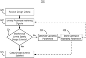
- FIG. 3 illustrates one embodiment of a method of determining feasibility of a fixed microwave network 300 .
- the method 300 shown in FIG. 3 is described herein as being implemented in the systems shown in FIGS. 1 and 2 , it is to be understood that other embodiments can be implemented in other ways.
- the blocks of the flow diagrams have been arranged in a generally sequential manner for ease of explanation; however, it is to be understood that this arrangement is merely exemplary, and it should be recognized that the processing associated with the methods (and the blocks shown in the Figures) can occur in a different order (for example, where at least some of the processing associated with the blocks is performed in parallel and/or in an event-driven manner).
- the method of determining feasibility is performed to confirm design criteria of a proposed fixed microwave network.
- receive such design criteria e.g. supplied by one of the external database(s) 216 or entered using the I/O(s) 218 , e.g. by a design tool or entered by a system designer.
- Proximate interfering signals would be signals having a power level above minimum criteria at a location of a radio system being analyzed.
- the minimum criteria for each proximate interfering signal can be lower than a power level that would cause the interference criteria to not satisfy specified criteria. This is because the power levels of more than one signal can be combined, e.g. taking into account the interference power aggregation of the different signals, to achieve the power level that would cause the interference criteria not to be satisfied.
- the networks database 212 B may first communicate with the external database(s) 216 to obtain information about new fixed microwave networks about which it is unaware, and then update the networks database 212 B.
- Proximate interfering signals may be ascertained by using modelled and/or measured data.
- Modelled data is generated using the propagation modelling system 212 A- 1 and geographic database 212 A- 2 using corresponding data in the networks database 212 B.
- the generated modelled data is stored in the parameter database 212 C.
- block 324 determine, e.g. with the data analysis system 212 A- 3 , if the interference levels, e.g. carrier to interference ratios, satisfies, e.g. exceeds, the proposed design criteria of the radio systems of the proposed fixed microwave network. In one embodiment, if the interference ratio satisfies the design criteria, then, in block 325 , output that that the interference design criteria has been satisfied, e.g. to a user or system requesting such information for example using the I/O(s) 218 .
- the interference levels e.g. carrier to interference ratios
- optimize radio system operating parameters e.g. transmitter power level, frequency of operation, modulation type and/or maximum data rate, and polarization, of the radio systems of the radio network whose feasibility is being ascertained.
- store the optimized parameters e.g. in the parameter database 212 C. Then, in a further embodiment, return to block 322 . Alternatively, proceed to block 325 .
- FIG. 4 illustrates one embodiment of a method of evaluating and optimizing an installation of a fixed microwave network 400 .
- the method 400 shown in FIG. 4 is described herein as being implemented in the systems shown in FIGS. 1 and 2 , it is to be understood that other embodiments can be implemented in other ways.
- the blocks of the flow diagrams have been arranged in a generally sequential manner for ease of explanation; however, it is to be understood that this arrangement is merely exemplary, and it should be recognized that the processing associated with the methods (and the blocks shown in the Figures) can occur in a different order (for example, where at least some of the processing associated with the blocks is performed in parallel and/or in an event-driven manner).
- the method of determining feasibility of an installation is performed to confirm proper operation of the fixed microwave network being installed.
- program radio systems, of a fixed microwave network e.g. with radio system operating parameters, e.g. transmitter power level, frequency of operation, modulation type and/or maximum data rate, and antenna polarization.
- perform such programming with the data analysis system 212 A- 3 .
- block 432 e.g. with the data analysis system 212 A- 3 , enable operation of the radio systems of the fixed microwave network.
- monitor a frequency spectrum including the frequency spectrum adjacent to the spectrum in which the fixed microwave network being installed is designed to operate.
- store data associated with monitored data e.g. maximum signal strength by frequency or frequency band, in the data analysis system 212 A- 3 .
- transmit data e.g. test data
- transmit data e.g. test data
- determine e.g. with the data analysis system 212 A- 3 , interference levels at the operating frequencies of the radio systems.
- determine whether interference levels satisfy the design criteria of the radio systems e.g. with the data analysis system 212 A- 3 .
- determining whether the interference levels satisfies the design criteria comprises satisfying carrier to interference criteria and/or link availability criteria, e.g. in the presence of interference.
- block 444 optimize, as described above, radio system operating parameters of the fixed microwave network being installed.
- block 446 store corresponding updated parameters, e.g. in the parameter database 212 C.
- block 448 program the updated parameters into the radio systems of the fixed microwave network being installed. In one embodiment return to block 442 . Alternatively, in another embodiment, proceed to block 438 .
- FIG. 5 illustrates one embodiment of a method of evaluating link availability of a fixed microwave network 500 .
- the method 500 shown in FIG. 5 is described herein as being implemented in the systems shown in FIGS. 1 and 2 , it is to be understood that other embodiments can be implemented in other ways.
- the blocks of the flow diagrams have been arranged in a generally sequential manner for ease of explanation; however, it is to be understood that this arrangement is merely exemplary, and it should be recognized that the processing associated with the methods (and the blocks shown in the Figures) can occur in a different order (for example, where at least some of the processing associated with the blocks is performed in parallel and/or in an event-driven manner).
- link availability of the corresponding fixed microwave network is evaluated to determine if each network link satisfies corresponding link availability design criteria.
- link availability design criteria e.g. if poor performance of a fixed microwave system is detected, optimize, as described above, radio systems operating parameters of the fixed microwave network.
- such optimization includes performing data analysis, e.g. data mining, (of measured and recorded data to correlate diminished performance events with operational characteristics of the radio systems) and using the data analysis results to determine the optimized radio systems operating parameters.
- program radio systems of a fixed microwave network with radio system operating parameters, e.g. transmitter power level, frequency of operation, modulation type and/or maximum data rate, and antenna polarization.
- radio system operating parameters e.g. transmitter power level, frequency of operation, modulation type and/or maximum data rate, and antenna polarization.
- perform such programming with the data analysis system 212 A- 3 .
- block 554 perform fade margin testing for one or more transmission data rates, e.g. by transmitting attenuated signals from each radio system in the fixed microwave network and generating parameter(s) characterizing quality of the corresponding received signals at other radio system(s) in the fixed microwave network.
- the quality of the signals is characterized by the extent the transmitted signal is received, e.g. for digital transmissions a bit error rate.
- attenuate the transmitted signal by one to fifty decibels, e.g. with variable attenuators at the output of the transmitter of the corresponding radio system or by reducing amplification gain in the transmitter.
- commence with block 554 if a new installation is being evaluated, commence with block 554 .
- the link availability design criteria correspond to parameter(s), e.g. minimum bit error rate or signal to noise ratio, necessary to maintain a certain level of link availability.
- the link availability criteria are stored with other design parameters in the parameters database 212 C. Link availability is the percentage of time during a period that the communications is uninterrupted and/or transmits data error free.
- link availability criteria are satisfied, then in block 560 , output that the link availability criteria are satisfied, e.g. to an installer of the fixed microwave network being installed (for example using the I/O(s) 218 ). If the link availability is not satisfied, then return to block 550 . In one embodiment, limit the number of times that operating parameters are optimized to N times, e.g. where N equals ten; if the link availability criteria are not satisfied after the Nth failure to satisfy the link availability criteria, then output that the link availability criteria cannot be satisfied, e.g. to the installer.
- Example 1 includes a system, comprising: processing system, comprising: a spectrum management system; a networks database; a parameter database; and a radio system database; a communications system coupled to the processing system; wherein the system is configured to be coupled to at least two radio systems; and wherein the spectrum management system is configured to perform at least one of: evaluating whether interference levels, at each radio system of a proposed fixed microwave network, satisfy interference criteria of that radio system; verifying whether interference levels, at each radio system of a fixed microwave network being installed, satisfy interference criteria of that radio system; and upon installation, or after deployment and upon detection of poor network performance, verifying that link availability criteria of a fixed microwave network are satisfied.
- Example 2 includes the system of Example 1, wherein the spectrum management system comprises: a propagation modelling system; a geographic database; a data analysis system; and an optimization system.
- the spectrum management system comprises: a propagation modelling system; a geographic database; a data analysis system; and an optimization system.
- Example 3 includes the system of any of Examples 1-2, wherein the system is configured to be coupled to at least one external database.
- Example 4 includes the system of Example 3, wherein one of the at least one external database comprises at least one of: (a) a database that stores data about at least one of: fixed microwave networks and other communications systems, and (b) a database that stores design criteria of fixed microwave network(s).
- Example 5 includes a method, comprising: receiving design criteria for a fixed microwave network; identifying proximate interfering signals; determining whether interference levels satisfy design criteria of the fixed microwave network; and if the interference levels do not satisfy the design criteria, then optimize operating parameters of radio systems of the fixed microwave network.
- Example 6 includes the method of Example 5, further comprising if the interference levels satisfy the design criteria, then outputting that the design criteria has been satisfied.
- Example 7 includes the method of any of Examples 5-6, wherein determining whether the interference levels satisfy the design criteria comprises determining whether the interference levels satisfy carrier to interference criteria.
- Example 8 includes a method, comprising: programming radio systems of a fixed microwave network; enabling the radio systems; monitoring frequency spectrum; transmitting data from the radio systems; determining interference levels; determining whether interference levels satisfy design criteria of the fixed microwave network; and if the interference levels do not satisfy the design criteria of the fixed microwave network, then: optimizing the operating parameters of the radio systems; and programming the radio systems with the optimized operating parameters.
- Example 9 includes the method of Example 8, wherein the determining whether the interference levels satisfy design criteria comprises determining whether the interference levels satisfies at least one of: carrier to interference criteria and link availability criteria.
- Example 10 includes the method of any of Examples 8-9, wherein if the interference levels satisfy the design criteria, then outputting that the network deployment is complete.
- Example 11 includes a method, comprising: performing fade margin testing of radio systems of a fixed microwave network; determining if link availability criteria of each radio system is satisfied; and if the link availability criteria for each radio system is not satisfied, then: optimizing operating parameters of each radio system that does not satisfy the link availability criteria; and programming each radio system that does not satisfy the link availability criteria with the optimized parameter.
- Example 12 includes the method of Example 11, wherein the fade margin testing comprises determining at least one parameter characterizing a quality of signals received by each radio system.
- Example 13 includes the method of Example 12, wherein the determining at least one parameter characterizing the quality of the signals received by each radio system comprises determining a bit error rate for the signals received by each radio system.
- Example 14 includes the method of any of Examples 11-13, wherein if the link availability criteria for each radio system is satisfied, then outputting that the link availability criteria is satisfied.
- Example 15 includes the method of any of Examples 11-14, wherein optimizing operating parameters comprises performing data analysis of measured and recorded data to correlate diminished performance events with operational characteristics of radio systems.
- Example 16 includes a non-transitory computer readable medium storing a program causing a computer to execute a process, the process comprising: receiving design criteria for a fixed microwave network; identifying proximate interfering signals; determining whether interference levels satisfy design criteria of the fixed microwave network; and if the interference levels do not satisfy the design criteria, then optimizing operating parameters of radio systems of the fixed microwave network.
- Example 17 includes the non-transitory computer readable medium of Example 16, wherein determining whether the interference levels satisfy the design criteria comprises determining whether the interference levels satisfy carrier to interference criteria.
- Example 18 includes a non-transitory computer readable medium storing a program causing a computer to execute a process, the process comprising: programming radio systems of a fixed microwave network; enabling the radio systems; monitoring frequency spectrum; transmitting data from the radio systems; determining interference levels; determining whether interference levels satisfy design criteria of the fixed microwave network; and if the interference levels do not satisfy the design criteria of the fixed microwave network, then: optimizing the operating parameters of the radio systems; and programming the radio systems with the optimized operating parameters.
- Example 19 includes the non-transitory computer readable medium of Example 18, wherein the determining whether the interference levels satisfy design criteria comprises determining whether the interference levels satisfies at least one of: carrier to interference criteria and link availability criteria.
- Example 20 includes a non-transitory computer readable medium storing a program causing a computer to execute a process, the process comprising: performing fade margin testing of radio systems of a fixed microwave network; determining if link availability criteria of each radio system is satisfied; and if the link availability criteria for each radio system is not satisfied, then: optimizing operating parameters of each radio system that does not satisfy the link availability criteria; and programming each radio system that does not satisfy the link availability criteria with the optimized parameter.
- Example 21 includes the non-transitory computer readable medium of Example 20, wherein the fade margin testing comprises determining at least one parameter characterizing a quality of signals received by each radio system.
- Example 22 includes the non-transitory computer readable medium of any of Examples 20-21, wherein optimizing operating parameters comprises performing data analysis of measured and recorded data to correlate diminished performance events with operational characteristics of radio systems.
- a signal may be a voltage signal or a current signal.
Abstract
Description
Claims (14)
Priority Applications (1)
| Application Number | Priority Date | Filing Date | Title |
|---|---|---|---|
| US16/636,595 US11240675B2 (en) | 2017-08-09 | 2018-06-05 | Method and system for planning and operating fixed microwave communications systems |
Applications Claiming Priority (3)
| Application Number | Priority Date | Filing Date | Title |
|---|---|---|---|
| US201762542847P | 2017-08-09 | 2017-08-09 | |
| US16/636,595 US11240675B2 (en) | 2017-08-09 | 2018-06-05 | Method and system for planning and operating fixed microwave communications systems |
| PCT/US2018/035982 WO2019032174A1 (en) | 2017-08-09 | 2018-06-05 | Method and system for planning and operating fixed microwave communications systems |
Publications (2)
| Publication Number | Publication Date |
|---|---|
| US20200389799A1 US20200389799A1 (en) | 2020-12-10 |
| US11240675B2 true US11240675B2 (en) | 2022-02-01 |
Family
ID=65271371
Family Applications (1)
| Application Number | Title | Priority Date | Filing Date |
|---|---|---|---|
| US16/636,595 Active 2038-07-12 US11240675B2 (en) | 2017-08-09 | 2018-06-05 | Method and system for planning and operating fixed microwave communications systems |
Country Status (2)
| Country | Link |
|---|---|
| US (1) | US11240675B2 (en) |
| WO (1) | WO2019032174A1 (en) |
Families Citing this family (7)
| Publication number | Priority date | Publication date | Assignee | Title |
|---|---|---|---|---|
| EP3619930A1 (en) * | 2017-12-15 | 2020-03-11 | Google LLC. | Establishing and terminating wireless links |
| CA3130675A1 (en) * | 2019-02-20 | 2020-08-27 | Commscope Technologies Llc | Frequency planning for a communication system |
| US11044158B2 (en) * | 2019-08-26 | 2021-06-22 | CACI, Inc.—Federal | Self-configuring wireless networks |
| US10728009B1 (en) | 2019-10-10 | 2020-07-28 | T-Mobile Usa, Inc. | Mitigating interference between base stations and microwave backhaul transceivers |
| US20210112550A1 (en) * | 2019-10-10 | 2021-04-15 | T-Mobile Usa, Inc. | Detecting interference between base stations and microwave backhaul transceivers |
| WO2024049332A1 (en) * | 2022-08-30 | 2024-03-07 | Telefonaktiebolaget Lm Ericsson (Publ) | A network control unit for coordinating an interference mitigation scheme in a microwave network |
| WO2024049333A1 (en) * | 2022-08-30 | 2024-03-07 | Telefonaktiebolaget Lm Ericsson (Publ) | A microwave communication node for detecting and mitigating interference |
Citations (18)
| Publication number | Priority date | Publication date | Assignee | Title |
|---|---|---|---|---|
| US5410737A (en) * | 1992-04-27 | 1995-04-25 | American Pcs L.P. | Frequency agile sharing technology (FAST) for a personal communications service system |
| US5497503A (en) * | 1993-05-28 | 1996-03-05 | Ameritech Corporation | Method for assigning frequency channels in a cellular communication system and for identifying critical existing fixed microwave receivers that restrict operation of such a system |
| US5548809A (en) * | 1992-07-15 | 1996-08-20 | Southwestern Bell Technology Resources, Inc. | Spectrum sharing communications system and system for monitoring available spectrum |
| US5752164A (en) * | 1992-04-27 | 1998-05-12 | American Pcs L.P. | Autonomous remote measurement unit for a personal communications service system |
| US6694141B1 (en) | 1997-06-24 | 2004-02-17 | Nokia Networks Oy | Channel selection in a radio link system |
| US20040137915A1 (en) | 2002-11-27 | 2004-07-15 | Diener Neil R. | Server and multiple sensor system for monitoring activity in a shared radio frequency band |
| US7269151B2 (en) | 2002-04-22 | 2007-09-11 | Cognio, Inc. | System and method for spectrum management of a shared frequency band |
| US20110250915A1 (en) | 2010-04-08 | 2011-10-13 | Peter Stanforth | System and method for managing radio access to spectrum and to a spectrum management system |
| US20110287802A1 (en) | 2010-05-06 | 2011-11-24 | Interdigital Patent Holdings, Inc. | Systems and methods for dynamic whitespace spectrum management |
| CN102870447A (en) | 2012-06-26 | 2013-01-09 | 华为技术有限公司 | Method and apparatus microwave network planning |
| US20130100869A1 (en) * | 2006-09-27 | 2013-04-25 | Dragonwave, Inc. | Wireless network communication apparatus, methods, and integrated antenna structures |
| WO2013116557A1 (en) | 2012-01-31 | 2013-08-08 | Comtech Ef Data Corp. | A method and system for real-time network link budget analysis |
| US20140038631A1 (en) * | 2011-04-29 | 2014-02-06 | Empire Technology Development, Llc | Optimizing cell traffic load and interference through high interference indicators |
| WO2014023351A1 (en) | 2012-08-09 | 2014-02-13 | Telefonaktiebolaget L M Ericsson (Publ) | Microwave link control |
| US20150230105A1 (en) | 2011-08-17 | 2015-08-13 | CBF Networks, Inc. | Self organizing backhaul radio |
| US9435882B2 (en) | 2012-09-11 | 2016-09-06 | The United States Of America As Represented By The Secretary Of The Army | Method and apparatus for cognitive nonlinear radar |
| US20170251495A1 (en) * | 2013-08-05 | 2017-08-31 | Sony Corporation | User device for communicating data and method |
| US20190124554A1 (en) * | 2011-07-15 | 2019-04-25 | Huawei Technologies Co., Ltd. | Wireless Broadband Communication Method, Device, and System, for Establishing a User Plane Connection Between a Small Cell and a User Equipment |
-
2018
- 2018-06-05 US US16/636,595 patent/US11240675B2/en active Active
- 2018-06-05 WO PCT/US2018/035982 patent/WO2019032174A1/en active Application Filing
Patent Citations (18)
| Publication number | Priority date | Publication date | Assignee | Title |
|---|---|---|---|---|
| US5752164A (en) * | 1992-04-27 | 1998-05-12 | American Pcs L.P. | Autonomous remote measurement unit for a personal communications service system |
| US5410737A (en) * | 1992-04-27 | 1995-04-25 | American Pcs L.P. | Frequency agile sharing technology (FAST) for a personal communications service system |
| US5548809A (en) * | 1992-07-15 | 1996-08-20 | Southwestern Bell Technology Resources, Inc. | Spectrum sharing communications system and system for monitoring available spectrum |
| US5497503A (en) * | 1993-05-28 | 1996-03-05 | Ameritech Corporation | Method for assigning frequency channels in a cellular communication system and for identifying critical existing fixed microwave receivers that restrict operation of such a system |
| US6694141B1 (en) | 1997-06-24 | 2004-02-17 | Nokia Networks Oy | Channel selection in a radio link system |
| US7269151B2 (en) | 2002-04-22 | 2007-09-11 | Cognio, Inc. | System and method for spectrum management of a shared frequency band |
| US20040137915A1 (en) | 2002-11-27 | 2004-07-15 | Diener Neil R. | Server and multiple sensor system for monitoring activity in a shared radio frequency band |
| US20130100869A1 (en) * | 2006-09-27 | 2013-04-25 | Dragonwave, Inc. | Wireless network communication apparatus, methods, and integrated antenna structures |
| US20110250915A1 (en) | 2010-04-08 | 2011-10-13 | Peter Stanforth | System and method for managing radio access to spectrum and to a spectrum management system |
| US20110287802A1 (en) | 2010-05-06 | 2011-11-24 | Interdigital Patent Holdings, Inc. | Systems and methods for dynamic whitespace spectrum management |
| US20140038631A1 (en) * | 2011-04-29 | 2014-02-06 | Empire Technology Development, Llc | Optimizing cell traffic load and interference through high interference indicators |
| US20190124554A1 (en) * | 2011-07-15 | 2019-04-25 | Huawei Technologies Co., Ltd. | Wireless Broadband Communication Method, Device, and System, for Establishing a User Plane Connection Between a Small Cell and a User Equipment |
| US20150230105A1 (en) | 2011-08-17 | 2015-08-13 | CBF Networks, Inc. | Self organizing backhaul radio |
| WO2013116557A1 (en) | 2012-01-31 | 2013-08-08 | Comtech Ef Data Corp. | A method and system for real-time network link budget analysis |
| CN102870447A (en) | 2012-06-26 | 2013-01-09 | 华为技术有限公司 | Method and apparatus microwave network planning |
| WO2014023351A1 (en) | 2012-08-09 | 2014-02-13 | Telefonaktiebolaget L M Ericsson (Publ) | Microwave link control |
| US9435882B2 (en) | 2012-09-11 | 2016-09-06 | The United States Of America As Represented By The Secretary Of The Army | Method and apparatus for cognitive nonlinear radar |
| US20170251495A1 (en) * | 2013-08-05 | 2017-08-31 | Sony Corporation | User device for communicating data and method |
Non-Patent Citations (1)
| Title |
|---|
| International Searching Authority, "International Search Report and Written Opinion from PCT Application No. PCT/US2018/035982", dated Sep. 19, 2018, pp. 1-13, Published: WO. |
Also Published As
| Publication number | Publication date |
|---|---|
| WO2019032174A1 (en) | 2019-02-14 |
| US20200389799A1 (en) | 2020-12-10 |
Similar Documents
| Publication | Publication Date | Title |
|---|---|---|
| US11240675B2 (en) | Method and system for planning and operating fixed microwave communications systems | |
| US20120184219A1 (en) | Method and apparatus for learning of the parameters of a fingerprint prediction map model | |
| US20130324147A1 (en) | Access Node Locations in a Network | |
| US11722239B2 (en) | System and method for monitoring wireless communication channel by using cooperative jamming and spoofing | |
| EP3169087A1 (en) | Gps signal acquisition method and distributed base station | |
| JP2012100153A (en) | Radio wave propagation characteristic estimation system, radio wave propagation characteristic estimation method, and computer program | |
| US11777805B2 (en) | Self-configuring wireless networks | |
| KR20170115804A (en) | Apparatus and Method for Analyzing Interference between Heterogeneous Wireless System considering Geographical Features | |
| CN103188709A (en) | Testing method, device and system for intermodulation interference | |
| Stéphan et al. | Increased reliability of outdoor millimeter-wave link simulations by leveraging lidar point cloud | |
| AU2013263206B2 (en) | Methods and systems for predicting jamming effectiveness | |
| US6844841B1 (en) | Radio frequency link performance tool process and system | |
| Colussi et al. | Multiyear trans-horizon radio propagation measurements at 3.5 GHz | |
| US11616709B2 (en) | Method and system for predicting availability in a radio frequency link aggregation group | |
| CN113162661B (en) | Beam forming equipment and beam forming method | |
| Kaschel et al. | Modeling and Simulation of the ITM Model for Point to Point Prediction on Digital Television extensible to other Technologies | |
| Michalek et al. | Analysis of signal attenuation in UHF band | |
| Molisch et al. | On pathloss models for adjacent-channel interference in cognitive whitespace systems | |
| Abdullah et al. | Utilization of NVIS HF Radio As Alternative Technologies In Rural Area of North Maluku | |
| US9692465B1 (en) | Aggregate interference model and use thereof to evaluate performance of a receiver | |
| ALMĂJANU et al. | Radio coverage analysis for mobile communication networks using ics telecom | |
| WO2007071059A1 (en) | Management of a satellite network using a network budget | |
| US10805806B2 (en) | Shared frequency management system and shared frequency management method | |
| CN114374979B (en) | Method and device for determining isolation distance between 5 GHz-band RLAN station and radar system | |
| Hao et al. | Case Study: Radio Application in a Smart Grid System for a Brownfield Onshore Dispersed oil Field: Copyright Material IEEE, Paper No. PCIC-2018-40 |
Legal Events
| Date | Code | Title | Description |
|---|---|---|---|
| AS | Assignment |
Owner name: COMMSCOPE TECHNOLOGIES LLC, NORTH CAROLINA Free format text: ASSIGNMENT OF ASSIGNORS INTEREST;ASSIGNORS:YOUNG, PETER S;MARZIN, JOSEPH;REEL/FRAME:051717/0925 Effective date: 20170814 |
|
| FEPP | Fee payment procedure |
Free format text: ENTITY STATUS SET TO UNDISCOUNTED (ORIGINAL EVENT CODE: BIG.); ENTITY STATUS OF PATENT OWNER: LARGE ENTITY |
|
| STPP | Information on status: patent application and granting procedure in general |
Free format text: DOCKETED NEW CASE - READY FOR EXAMINATION |
|
| STPP | Information on status: patent application and granting procedure in general |
Free format text: NON FINAL ACTION MAILED |
|
| STPP | Information on status: patent application and granting procedure in general |
Free format text: RESPONSE TO NON-FINAL OFFICE ACTION ENTERED AND FORWARDED TO EXAMINER |
|
| STPP | Information on status: patent application and granting procedure in general |
Free format text: NOTICE OF ALLOWANCE MAILED -- APPLICATION RECEIVED IN OFFICE OF PUBLICATIONS |
|
| AS | Assignment |
Owner name: JPMORGAN CHASE BANK, N.A., NEW YORK Free format text: ABL SECURITY AGREEMENT;ASSIGNORS:ARRIS ENTERPRISES LLC;COMMSCOPE TECHNOLOGIES LLC;COMMSCOPE, INC. OF NORTH CAROLINA;REEL/FRAME:058843/0712 Effective date: 20211112 Owner name: JPMORGAN CHASE BANK, N.A., NEW YORK Free format text: TERM LOAN SECURITY AGREEMENT;ASSIGNORS:ARRIS ENTERPRISES LLC;COMMSCOPE TECHNOLOGIES LLC;COMMSCOPE, INC. OF NORTH CAROLINA;REEL/FRAME:058875/0449 Effective date: 20211112 |
|
| AS | Assignment |
Owner name: WILMINGTON TRUST, DELAWARE Free format text: SECURITY INTEREST;ASSIGNORS:ARRIS SOLUTIONS, INC.;ARRIS ENTERPRISES LLC;COMMSCOPE TECHNOLOGIES LLC;AND OTHERS;REEL/FRAME:060752/0001 Effective date: 20211115 |
|
| STPP | Information on status: patent application and granting procedure in general |
Free format text: PUBLICATIONS -- ISSUE FEE PAYMENT VERIFIED |
|
| STCF | Information on status: patent grant |
Free format text: PATENTED CASE |