US11239878B2 - Method and system for interference cancellation in MIMO wireless system - Google Patents

Method and system for interference cancellation in MIMO wireless system Download PDF

Info

Publication number
US11239878B2
US11239878B2 US16/968,819 US201916968819A US11239878B2 US 11239878 B2 US11239878 B2 US 11239878B2 US 201916968819 A US201916968819 A US 201916968819A US 11239878 B2 US11239878 B2 US 11239878B2
Authority
US
United States
Prior art keywords
signals
ebd
antenna
circulator
transmitting signals
Prior art date
Legal status (The legal status is an assumption and is not a legal conclusion. Google has not performed a legal analysis and makes no representation as to the accuracy of the status listed.)
Active
Application number
US16/968,819
Other versions
US20210006285A1 (en
Inventor
Abhishek Kumar
Sankaran Aniruddhan
Radha Krishna Ganti
Current Assignee (The listed assignees may be inaccurate. Google has not performed a legal analysis and makes no representation or warranty as to the accuracy of the list.)
Indian Institute Of Technology Madra Iitm
Indian Institute of Technology Madras
Original Assignee
Indian Institute Of Technology Madra Iitm
Priority date (The priority date is an assumption and is not a legal conclusion. Google has not performed a legal analysis and makes no representation as to the accuracy of the date listed.)
Filing date
Publication date
Application filed by Indian Institute Of Technology Madra Iitm filed Critical Indian Institute Of Technology Madra Iitm
Assigned to INDIAN INSTITUTE OF TECHNOLOGY, MADRAS (IITM) reassignment INDIAN INSTITUTE OF TECHNOLOGY, MADRAS (IITM) ASSIGNMENT OF ASSIGNORS INTEREST (SEE DOCUMENT FOR DETAILS). Assignors: ANIRUDDHAN, SANKARAN, GANTI, RADHA KRISHNA, KUMAR, ABHISHEK
Publication of US20210006285A1 publication Critical patent/US20210006285A1/en
Application granted granted Critical
Publication of US11239878B2 publication Critical patent/US11239878B2/en
Active legal-status Critical Current
Anticipated expiration legal-status Critical

Links

Images

Classifications

    • HELECTRICITY
    • H04ELECTRIC COMMUNICATION TECHNIQUE
    • H04BTRANSMISSION
    • H04B1/00Details of transmission systems, not covered by a single one of groups H04B3/00 - H04B13/00; Details of transmission systems not characterised by the medium used for transmission
    • H04B1/38Transceivers, i.e. devices in which transmitter and receiver form a structural unit and in which at least one part is used for functions of transmitting and receiving
    • H04B1/40Circuits
    • H04B1/50Circuits using different frequencies for the two directions of communication
    • H04B1/52Hybrid arrangements, i.e. arrangements for transition from single-path two-direction transmission to single-direction transmission on each of two paths or vice versa
    • H04B1/525Hybrid arrangements, i.e. arrangements for transition from single-path two-direction transmission to single-direction transmission on each of two paths or vice versa with means for reducing leakage of transmitter signal into the receiver
    • HELECTRICITY
    • H04ELECTRIC COMMUNICATION TECHNIQUE
    • H04LTRANSMISSION OF DIGITAL INFORMATION, e.g. TELEGRAPHIC COMMUNICATION
    • H04L5/00Arrangements affording multiple use of the transmission path
    • H04L5/14Two-way operation using the same type of signal, i.e. duplex
    • HELECTRICITY
    • H04ELECTRIC COMMUNICATION TECHNIQUE
    • H04BTRANSMISSION
    • H04B1/00Details of transmission systems, not covered by a single one of groups H04B3/00 - H04B13/00; Details of transmission systems not characterised by the medium used for transmission
    • H04B1/02Transmitters
    • H04B1/04Circuits
    • H04B1/0483Transmitters with multiple parallel paths
    • HELECTRICITY
    • H04ELECTRIC COMMUNICATION TECHNIQUE
    • H04BTRANSMISSION
    • H04B7/00Radio transmission systems, i.e. using radiation field
    • H04B7/02Diversity systems; Multi-antenna system, i.e. transmission or reception using multiple antennas
    • H04B7/04Diversity systems; Multi-antenna system, i.e. transmission or reception using multiple antennas using two or more spaced independent antennas
    • H04B7/0413MIMO systems

Definitions

  • the present disclosure relates to a wireless communication system, and more specifically is related to a full duplex front-end circuit for a multiple-input-multiple-output (MIMO) wireless system.
  • MIMO multiple-input-multiple-output
  • the present application is based on, and claims priority from an Indian Application Number 201841005400 filed on 13 th Feb. 2018, and PCT/IN2019/050112 filed on 13 th Feb. 2019, the disclosure of which is hereby incorporated by reference the disclosure of which is hereby incorporated by reference herein.
  • Self-interference from a transmitter is major challenge in same channel full duplex (SCFD) front end circuit.
  • SCFD multiple input multiple output
  • MIMO multiple input multiple output
  • Tx transmitter
  • Tx multiple input multiple output
  • Rx receiver
  • Balance network in the EBD can be replaced by another antenna to get rid of the insertion loss. But both of these antennas together transmit and receive single spatial stream.
  • the principal object of the embodiments herein is to provide a transceiver system for interference cancellation in full-duplex communication.
  • Another object of the embodiments herein is to provide a full duplex front-end circuit for a multiple-input-multiple-output (MIMO) wireless system.
  • MIMO multiple-input-multiple-output
  • Another object of the embodiments herein is to provide an electrical balance based duplexer (EBD) configured to obtain wideband isolation between two streams in 2 ⁇ 2 MIMO same channel full duplex (SCFD) front-end without incurring any insertion loss.
  • EBD electrical balance based duplexer
  • Another object of the embodiments herein is to provide a reciprocal nature of antenna coupling for cross-talk cancellation, so as to reduce the number of coupling networks required for MIMO full-duplex operation.
  • the embodiments herein provide a transceiver system for full-duplex communication.
  • the transceiver system includes an electrical balance based duplexer (EBD) coupled with at least one transceiver and at least one antennas.
  • the at least one antennas is configured to transmit first signals and the at least one antennas is configured to receive second signals using at least one circulators.
  • the EBD is configured to provide an isolation between the transmitting signals and the receiving signals in a same channel full duplex (SCFD) front-end circuit using the at least one circulators.
  • SCFD channel full duplex
  • the EBD is configured to provide the isolation between the transmitting signals and the receiving signals in the SCFD front-end circuit using the at least one circulators by passing transmitting signals and the receiving signals at a first port from the plurality of ports and at a second port from the plurality of ports through the at least one circulators, equally dividing the transmitting signals and transmitting the transmitting signals through the at least one antennas, receiving a portion of the transmitting signals transmitted from a first antenna from the at least one antennas by a second antenna from the at least one antennas, and matching input impedance to provide wide-band isolation between the two Tx/Rx pairs under balanced condition between the transmitting signals and the receiving signals in the SCFD front-end circuit using the at least one circulators.
  • the EBD is configured to isolate the received signals from interference caused by the at least one transmitter.
  • the EBD is fed with the transmitting signals through the at least one circulator at a pair of isolated ports.
  • At least one signal interference (SI) cancellation circuit is placed in the at least one transceiver.
  • SI signal interference
  • a tuning network is placed between the at least one circulators and the EBD to manage the isolation of the first transmitting signals and the second receiving signals.
  • a vector modulator is placed between the at least one circulators and the EBD to manage the isolation between isolation of the first transmitting signals and the second receiving signals by the at least one circulators.
  • the embodiments herein provide a method for interference cancellation in full-duplex communication.
  • the method includes detecting, by an EBD, transmitting signals from at least one antennas. Further, the method includes detecting, by the EBD, receiving signals from the at least one antennas. Further, the method includes providing, by the EBD, an isolation between the transmitting signals and the receiving signals in a SCFD front-end circuit using at least one circulators.
  • FIG. 1 is a schematic diagram illustrating 2 ⁇ 2 MIMO SCFD front-end for a MIMO wireless system, according to embodiments as disclosed herein;
  • FIG. 2 is a schematic diagram illustrating 2 ⁇ 2 MIMO SCFD front-end with a tuning network for the MIMO wireless system, according to embodiments as disclosed herein;
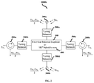
  • FIG. 3 is a schematic diagram illustrating 2 ⁇ 2 MIMO SCFD front-end with the tuning network and a vector modulator for MIMO wireless system, according to embodiments as disclosed herein;
  • FIG. 4 is a schematic diagram illustrating 2 ⁇ 2 MIMO SCFD front-end with the tuning network and multiple output vector modulator for the MIMO wireless system, according to embodiments as disclosed herein;
  • FIG. 5 and FIG. 6 are schematic diagram illustrating 4 ⁇ 4 MIMO SCFD front-end for the MIMO wireless system, according to embodiments as disclosed herein;
  • FIG. 7 is a flow diagram illustrating a method for managing an interference cancellation in the MIMO wireless system, according to embodiments as disclosed herein.
  • circuits may, for example, be embodied in one or more semiconductor chips, or on substrate supports such as printed circuit boards and the like.
  • circuits constituting a block may be implemented by dedicated hardware, or by a processor (e.g., one or more programmed microprocessors and associated circuitry), or by a combination of dedicated hardware to perform some functions of the block and a processor to perform other functions of the block.
  • a processor e.g., one or more programmed microprocessors and associated circuitry
  • Each block of the embodiments may be physically separated into two or more interacting and discrete blocks without departing from the scope of the invention.
  • the blocks of the embodiments may be physically combined into more complex blocks without departing from the scope of the invention.
  • the embodiments herein achieve a transceiver system for full-duplex communication.
  • the transceiver system includes an electrical balance based duplexer (EBD) coupled with at least one transceiver and at least one antennas.
  • the at least one antennas is configured to transmit first signals and the at least one antennas is configured to receive second signals using at least one circulators.
  • the EBD is configured to provide an isolation between the transmitting signals and the receiving signals in a same channel full duplex (SCFD) front-end circuit using the at least one circulators.
  • SCFD channel full duplex
  • the EBD is configured to obtain a wideband isolation between the two streams in 2 ⁇ 2 MIMO same channel full duplex (SCFD) front-end without incurring any insertion loss.
  • SCFD same channel full duplex
  • the proposed transceiver system can be used to transmit and receive two independent spatial streams using two antennas of the EBD.
  • the transceiver system can be used to provide Tx-Rx isolation to achieve SCFD operation in 2 ⁇ 2 MIMO using the circulators.
  • the transceiver system can be used to isolate received signal from interference caused by transmitter of other stream using the EBD.
  • a reciprocal nature of antenna coupling provides a cross-talk cancellation, so as to reduce the number of coupling networks required for MIMO full-duplex operation.
  • the proposed system can be used to cancel cross-talk between two Tx-Rx pairs in the presence of antenna coupling in the MIMO wireless system. This is achieved by connecting two antennas and two Tx-Rx pairs through the EBD.
  • FIGS. 1 through 7 there are shown preferred embodiments.
  • FIG. 1 is a schematic diagram illustrating 2 ⁇ 2 MIMO SCFD front-end circuit for a MIMO wireless system, according to embodiments as disclosed herein.
  • the transceiver system 1000 a includes an electrical balance based duplexer (EBD) 100 coupled with at least one transceiver 200 a and 200 b and at least one antennas 300 a and 300 b .
  • the at least one antennas 300 a and 300 b is configured to transmit first signals and the at least one antennas 300 a and 300 b is configured to receive second signals using at least one circulators (not shown).
  • the EBD 100 is configured to provide an isolation between the transmitting signals and the receiving signals in a same channel full duplex (SCFD) front-end circuit using the at least one circulators.
  • the EBD 100 isolates received signal from interference caused by a transmitter (not shown) of other stream.
  • Tx and Rx are shown isolated using the at least one circulator, which can be replaced with any other SI cancellation circuit.
  • the Tx/Rx pairs are connected to sum and difference ports of the EBD 100 .
  • the EBD 100 can also be called as a coupler. Since the two antennas 300 a and 300 b will have closely matched input impedance, this configuration will result in wideband isolation between the two Tx/Rx pairs under balanced condition. In the presence of reflectors (not shown) in the antenna environment which are common to both the antennas, reflected signal will only appear at a respective Rx port.
  • the EBD 100 is fed with two transmitting signals Tx 1 and Tx 2 , through two circulators at a pair of isolated ports (not shown). As a result, linear combination of the two Tx signals are transmitted by the two antennas 300 a and 300 b . Similarly linear combination of signal received by the two antennas 300 a and 300 b is collected at the two circulators. Further, the circulators provide Tx-Rx isolation to achieve SCFD operation.
  • the EBD 100 isolates received signal from interference caused by the transmitter of other stream.
  • the EBD 200 in the proposal transceiver system 1000 a can be replaced by any 4 port device which provide similar functionality for example a 180 degree hybrid system 400 . Operations and function of the 180 degree hybrid system 400 is similar to the EBD 100 .
  • the transceiver system 1000 a can be used to transmit the linear combination of the two Tx signals using the two antennas 300 a and 300 b .
  • the transceiver system 1000 a can be used to collect the linear combination of signals received by the two antennas 300 a and 300 b using two circulators.
  • a reciprocal coupling network arranged between transceiver pairs and antennas based on the EBD 100 is for the MIMO system reduces the number of cross-connecting networks and variables required to mitigate cross-talk interference (CI) and maintain reliable CI cancellation in the presence of common-mode reflectors.
  • CI cross-talk interference
  • Tx and Rx are shown isolated using the circulator.
  • Tx/Rx pairs through the circulator are connected to a sum port ( ⁇ ) and difference ( ⁇ ) port of the EBD 100 .
  • the first port is a sum port and a second port is a difference ( ⁇ ) port.
  • the signal from Tx 1 is divided equally and transmitted through the two antennas 300 a and 300 b . Due to the antennas interaction, the part of the signal transmitted from one antenna 200 a is received by another antenna 200 b and vice-versa.
  • the reciprocal nature of the antenna coupling ensures that equal and same phase signal couples to the two antennas 300 a and 300 b .
  • the coupled signal is cancelled at the difference port and appear only at a receiver connected to the sum port which can be treated as self-interference.
  • signal from the Tx 2 when couples back to the antennas 300 a and 300 b only appears at the receiver connected to the difference port. Since the two antennas will 300 a and 300 b have closely matched input impedance, this configuration will result in wide-band isolation between the two Tx/Rx pairs under a balanced condition.
  • Above discussion can be extended to show that in the presence of reflectors in the antenna environment which are common to both the antennas, reflected signal just like coupled signal will only appear as self-interference.
  • FIG. 2 is a schematic diagram illustrating 2 ⁇ 2 MIMO SCFD front-end with at least one tuning network 500 a - 500 d for the MIMO wireless system, according to embodiments as disclosed herein.
  • the transceiver system 1000 b includes the EBD 100 coupled with at least one transceiver 200 a and 200 b and at least one antennas 300 a and 300 b .
  • the operations and functions of the EBD 100 , the at least one transceiver 200 a and 200 b and the at least one antennas 300 a and 300 b are explained in conjunction with the FIG. 1 .
  • the tuning networks 500 a - 500 d is placed between the at least one circulators and the EBD 200 to manage the isolation of the first transmitting signals and the second receiving signals to improve Tx-Rx isolation in the MIMO wireless system.
  • the tuning networks 500 a - 500 d includes tunable circuit elements for enabling the variable impedance transformation in the MIMO wireless system.
  • the EBD 200 in the proposal transceiver system 1000 b can be replaced by any 4 port device which provide similar functionality for example the 180 degree hybrid system 400 .
  • FIG. 3 is a schematic diagram illustrating 2 ⁇ 2 MIMO SCFD front-end with tuning network and vector modulator for MIMO wireless system, according to embodiments as disclosed herein.
  • the transceiver system 1000 c includes the EBD 100 coupled with at least one transceiver 200 a and 200 b and at least one antennas 300 a and 300 b .
  • the tuning networks 500 a - 500 d is placed between the at least one circulators and the EBD 200 to manage the isolation of the first transmitting signals and the second receiving signals to improve Tx-Rx isolation in the MIMO wireless system.
  • the operations and functions of the EBD 100 , the at least one transceiver 200 a and 200 b , the at least one antennas 300 a and 300 b , and the tuning networks 500 a - 500 d are explained in conjunction with the FIG. 1 and FIG. 2 .
  • the at least one signal interference (SI) cancellation circuit 600 a and 600 b is placed in the at least one transceiver 200 a and 200 b .
  • the vector modulator (or delay tapped filter) can be added in the transceiver system 1000 c to increase isolation between Tx-Rx pair isolated by the circulator.
  • the SI cancellation circuit 600 a and 600 b taps small part of Tx signal and transforms the Tx signal such that when added to main path, residual Tx signal in a main path is reduced.
  • the SI cancellation circuit 600 a and 600 b can be realized using the vector modulator or delay tapped filter.
  • FIG. 4 is a schematic diagram illustrating 2 ⁇ 2 MIMO SCFD front-end with the tuning network 500 a - 500 d and multiple output vector modulator for the MIMO wireless system, according to embodiments as disclosed herein.
  • the operations and functions of the EBD 100 , the at least one transceiver 200 a and 200 b , the at least one antennas 300 a and 300 b , the tuning networks 500 a - 500 d , and the vector modulator (or delay tapped filter) are explained in conjunction with the FIG. 1 - FIG. 3 .
  • multiple output vector modulator or delay tapped filter added to increase isolation between Tx-Rx pair isolated by the circulator as well as the EBD 200 .
  • FIG. 5 and FIG. 6 are schematic diagrams illustrating 4 ⁇ 4 MIMO SCFD front-end for the MIMO wireless system, according to embodiments as disclosed herein.
  • the proposed system can be extended to include more number of spatial streams.
  • the operations and functions of the EBD 100 , the at least one transceiver 200 a and 200 b , the at least one antennas 300 a and 300 b , the tuning networks 500 a - 500 d , and the vector modulator (or delay tapped filter) are explained in conjunction with the FIG. 1 - FIG. 4 .
  • FIG. 7 is a flow diagram 700 illustrating a method for managing the interference cancellation in the MIMO wireless system, according to embodiments as disclosed herein.
  • the method includes detecting, by the EBD 100 , transmitting signals from the at least one antennas 300 a and 300 b .
  • the method includes detecting, by the EBD 100 , receiving signals from the at least one antennas 300 a and 300 b .
  • the method includes providing, by the EBD 100 , the isolation between the transmitting signals and the receiving signals in the SCFD front-end circuit using the at least one circulators.

Abstract

Embodiments herein provide a transceiver system 1000 a-1000 f for full-duplex communication. The transceiver system 1000 a-1000 f includes an electrical balance based duplexer (EBD) 100 coupled with at least one transceiver 200 a and 200 b and at least one antenna 300 a and 300 b. The at least one antenna 300 a and 300 b is configured to transmit first signals and the at least one antennas 300 a and 300 b is configured to receive second signals using at least one circulators. The EBD 100 is configured to provide an isolation between the transmitting signals and the receiving signals in a same channel full duplex (SCFD) front-end circuit using the at least one circulators.

Description

FIELD OF INVENTION
The present disclosure relates to a wireless communication system, and more specifically is related to a full duplex front-end circuit for a multiple-input-multiple-output (MIMO) wireless system. The present application is based on, and claims priority from an Indian Application Number 201841005400 filed on 13th Feb. 2018, and PCT/IN2019/050112 filed on 13th Feb. 2019, the disclosure of which is hereby incorporated by reference the disclosure of which is hereby incorporated by reference herein.
BACKGROUND
Self-interference from a transmitter is major challenge in same channel full duplex (SCFD) front end circuit. In multiple input multiple output (MIMO) SCFD system, signal leakage from another transmitting stream makes the interference even worse. The self-interference from the transmitter (Tx) can be suppressed using electrical balance based duplexer (EBD) like hybrid transformer. However, they suffer from insertion loss in Tx and receiver (Rx) paths. Balance network in the EBD can be replaced by another antenna to get rid of the insertion loss. But both of these antennas together transmit and receive single spatial stream.
Many conventional methods and circuit arrangements are proposed for isolating two or more TX paths from the two or more RX paths and to provide low-loss signal paths between output nodes of two or more transmit (TX) paths and the one or more antennas but, includes disadvantages in terms of power consumption, robustness, reliability, integrity issues, operation dependency, time, cost, complexity, design, hardware components used, size and so on.
Thus, it is desired to address the above mentioned disadvantages or other shortcomings or at least provide a useful alternative.
Object of Invention
The principal object of the embodiments herein is to provide a transceiver system for interference cancellation in full-duplex communication.
Another object of the embodiments herein is to provide a full duplex front-end circuit for a multiple-input-multiple-output (MIMO) wireless system.
Another object of the embodiments herein is to provide an electrical balance based duplexer (EBD) configured to obtain wideband isolation between two streams in 2×2 MIMO same channel full duplex (SCFD) front-end without incurring any insertion loss.
Another object of the embodiments herein is to provide a reciprocal nature of antenna coupling for cross-talk cancellation, so as to reduce the number of coupling networks required for MIMO full-duplex operation.
SUMMARY
Accordingly, the embodiments herein provide a transceiver system for full-duplex communication. The transceiver system includes an electrical balance based duplexer (EBD) coupled with at least one transceiver and at least one antennas. The at least one antennas is configured to transmit first signals and the at least one antennas is configured to receive second signals using at least one circulators. The EBD is configured to provide an isolation between the transmitting signals and the receiving signals in a same channel full duplex (SCFD) front-end circuit using the at least one circulators.
In an embodiment, the EBD is configured to provide the isolation between the transmitting signals and the receiving signals in the SCFD front-end circuit using the at least one circulators by passing transmitting signals and the receiving signals at a first port from the plurality of ports and at a second port from the plurality of ports through the at least one circulators, equally dividing the transmitting signals and transmitting the transmitting signals through the at least one antennas, receiving a portion of the transmitting signals transmitted from a first antenna from the at least one antennas by a second antenna from the at least one antennas, and matching input impedance to provide wide-band isolation between the two Tx/Rx pairs under balanced condition between the transmitting signals and the receiving signals in the SCFD front-end circuit using the at least one circulators.
In an embodiment, the EBD is configured to isolate the received signals from interference caused by the at least one transmitter.
In an embodiment, the EBD is fed with the transmitting signals through the at least one circulator at a pair of isolated ports.
In an embodiment, at least one signal interference (SI) cancellation circuit is placed in the at least one transceiver.
In an embodiment, a tuning network is placed between the at least one circulators and the EBD to manage the isolation of the first transmitting signals and the second receiving signals.
In an embodiment, a vector modulator is placed between the at least one circulators and the EBD to manage the isolation between isolation of the first transmitting signals and the second receiving signals by the at least one circulators.
Accordingly, the embodiments herein provide a method for interference cancellation in full-duplex communication. The method includes detecting, by an EBD, transmitting signals from at least one antennas. Further, the method includes detecting, by the EBD, receiving signals from the at least one antennas. Further, the method includes providing, by the EBD, an isolation between the transmitting signals and the receiving signals in a SCFD front-end circuit using at least one circulators.
These and other aspects of the embodiments herein will be better appreciated and understood when considered in conjunction with the following description and the accompanying drawings. It should be understood, however, that the following descriptions, while indicating preferred embodiments and numerous specific details thereof, are given by way of illustration and not of limitation. Many changes and modifications may be made within the scope of the embodiments herein without departing from the spirit thereof, and the embodiments herein include all such modifications.
BRIEF DESCRIPTION OF FIGURES
This method is illustrated in the accompanying drawings, throughout which like reference letters indicate corresponding parts in the various figures. The embodiments herein will be better understood from the following description with reference to the drawings, in which:
FIG. 1 is a schematic diagram illustrating 2×2 MIMO SCFD front-end for a MIMO wireless system, according to embodiments as disclosed herein;
FIG. 2 is a schematic diagram illustrating 2×2 MIMO SCFD front-end with a tuning network for the MIMO wireless system, according to embodiments as disclosed herein;
FIG. 3 is a schematic diagram illustrating 2×2 MIMO SCFD front-end with the tuning network and a vector modulator for MIMO wireless system, according to embodiments as disclosed herein;
FIG. 4 is a schematic diagram illustrating 2×2 MIMO SCFD front-end with the tuning network and multiple output vector modulator for the MIMO wireless system, according to embodiments as disclosed herein;
FIG. 5 and FIG. 6 are schematic diagram illustrating 4×4 MIMO SCFD front-end for the MIMO wireless system, according to embodiments as disclosed herein; and
FIG. 7 is a flow diagram illustrating a method for managing an interference cancellation in the MIMO wireless system, according to embodiments as disclosed herein.
DETAILED DESCRIPTION OF INVENTION
The embodiments herein and the various features and advantageous details thereof are explained more fully with reference to the non-limiting embodiments that are illustrated in the accompanying drawings and detailed in the following description. Descriptions of well-known components and processing techniques are omitted so as to not unnecessarily obscure the embodiments herein. Also, the various embodiments described herein are not necessarily mutually exclusive, as some embodiments can be combined with one or more of other embodiments to form new embodiments. The term “or” as used herein, refers to a “non-exclusive or”, unless otherwise indicated. The examples used herein are intended merely to facilitate an understanding of ways in which the embodiments herein can be practiced and to further enable those skilled in the art to practice the embodiments herein. Accordingly, the examples should not be construed as limiting the scope of the embodiments herein.
As is traditional in the field, embodiments may be described and illustrated in terms of blocks which carry out a described function or functions. These blocks, which may be referred to herein as units or modules or the like, are physically implemented by analog or digital circuits such as logic gates, integrated circuits, microprocessors, microcontrollers, memory circuits, passive electronic components, active electronic components, optical components, hardwired circuits, or the like, and may optionally be driven by firmware and software. The circuits may, for example, be embodied in one or more semiconductor chips, or on substrate supports such as printed circuit boards and the like. The circuits constituting a block may be implemented by dedicated hardware, or by a processor (e.g., one or more programmed microprocessors and associated circuitry), or by a combination of dedicated hardware to perform some functions of the block and a processor to perform other functions of the block. Each block of the embodiments may be physically separated into two or more interacting and discrete blocks without departing from the scope of the invention. Likewise, the blocks of the embodiments may be physically combined into more complex blocks without departing from the scope of the invention.
The accompanying drawings are used to help easily understand various technical features and it should be understood that the embodiments presented herein are not limited by the accompanying drawings. As such, the present disclosure should be construed to extend to any alterations, equivalents and substitutes in addition to those which are particularly set out in the accompanying drawings. Although the terms first, second, etc. may be used herein to describe various elements, these elements should not be limited by these terms. These terms are generally only used to distinguish one element from another.
Accordingly, the embodiments herein achieve a transceiver system for full-duplex communication. The transceiver system includes an electrical balance based duplexer (EBD) coupled with at least one transceiver and at least one antennas. The at least one antennas is configured to transmit first signals and the at least one antennas is configured to receive second signals using at least one circulators. The EBD is configured to provide an isolation between the transmitting signals and the receiving signals in a same channel full duplex (SCFD) front-end circuit using the at least one circulators.
Unlike conventional methods and systems, the EBD is configured to obtain a wideband isolation between the two streams in 2×2 MIMO same channel full duplex (SCFD) front-end without incurring any insertion loss. Further, the proposed transceiver system can be used to transmit and receive two independent spatial streams using two antennas of the EBD.
The transceiver system can be used to provide Tx-Rx isolation to achieve SCFD operation in 2×2 MIMO using the circulators. The transceiver system can be used to isolate received signal from interference caused by transmitter of other stream using the EBD.
In the proposed transceiver system, a reciprocal nature of antenna coupling provides a cross-talk cancellation, so as to reduce the number of coupling networks required for MIMO full-duplex operation.
The proposed system can be used to cancel cross-talk between two Tx-Rx pairs in the presence of antenna coupling in the MIMO wireless system. This is achieved by connecting two antennas and two Tx-Rx pairs through the EBD.
Referring now to the drawings, and more particularly to FIGS. 1 through 7, there are shown preferred embodiments.
FIG. 1 is a schematic diagram illustrating 2×2 MIMO SCFD front-end circuit for a MIMO wireless system, according to embodiments as disclosed herein.
As shown in the FIG. 1, the transceiver system 1000 a includes an electrical balance based duplexer (EBD) 100 coupled with at least one transceiver 200 a and 200 b and at least one antennas 300 a and 300 b. The at least one antennas 300 a and 300 b is configured to transmit first signals and the at least one antennas 300 a and 300 b is configured to receive second signals using at least one circulators (not shown). The EBD 100 is configured to provide an isolation between the transmitting signals and the receiving signals in a same channel full duplex (SCFD) front-end circuit using the at least one circulators. The EBD 100 isolates received signal from interference caused by a transmitter (not shown) of other stream.
In an embodiment, in each transceiver 200 a and 200 b, Tx and Rx are shown isolated using the at least one circulator, which can be replaced with any other SI cancellation circuit. The Tx/Rx pairs are connected to sum and difference ports of the EBD 100. The EBD 100 can also be called as a coupler. Since the two antennas 300 a and 300 b will have closely matched input impedance, this configuration will result in wideband isolation between the two Tx/Rx pairs under balanced condition. In the presence of reflectors (not shown) in the antenna environment which are common to both the antennas, reflected signal will only appear at a respective Rx port.
In an example, the EBD 100 is fed with two transmitting signals Tx1 and Tx2, through two circulators at a pair of isolated ports (not shown). As a result, linear combination of the two Tx signals are transmitted by the two antennas 300 a and 300 b. Similarly linear combination of signal received by the two antennas 300 a and 300 b is collected at the two circulators. Further, the circulators provide Tx-Rx isolation to achieve SCFD operation. The EBD 100 isolates received signal from interference caused by the transmitter of other stream. In another embodiment, the EBD 200 in the proposal transceiver system 1000 a can be replaced by any 4 port device which provide similar functionality for example a 180 degree hybrid system 400. Operations and function of the 180 degree hybrid system 400 is similar to the EBD 100.
Further, the transceiver system 1000 a can be used to transmit the linear combination of the two Tx signals using the two antennas 300 a and 300 b. The transceiver system 1000 a can be used to collect the linear combination of signals received by the two antennas 300 a and 300 b using two circulators.
Further, a reciprocal coupling network arranged between transceiver pairs and antennas based on the EBD 100 is for the MIMO system reduces the number of cross-connecting networks and variables required to mitigate cross-talk interference (CI) and maintain reliable CI cancellation in the presence of common-mode reflectors.
In each transceiver 200 a and 200 b, Tx and Rx are shown isolated using the circulator. Tx/Rx pairs through the circulator are connected to a sum port (Σ) and difference (Δ) port of the EBD 100. The first port is a sum port and a second port is a difference (Δ) port. The signal from Tx1 is divided equally and transmitted through the two antennas 300 a and 300 b. Due to the antennas interaction, the part of the signal transmitted from one antenna 200 a is received by another antenna 200 b and vice-versa. The reciprocal nature of the antenna coupling ensures that equal and same phase signal couples to the two antennas 300 a and 300 b. Therefore, the coupled signal is cancelled at the difference port and appear only at a receiver connected to the sum port which can be treated as self-interference. Similarly, it can be shown that signal from the Tx2 when couples back to the antennas 300 a and 300 b, only appears at the receiver connected to the difference port. Since the two antennas will 300 a and 300 b have closely matched input impedance, this configuration will result in wide-band isolation between the two Tx/Rx pairs under a balanced condition. Above discussion can be extended to show that in the presence of reflectors in the antenna environment which are common to both the antennas, reflected signal just like coupled signal will only appear as self-interference.
FIG. 2 is a schematic diagram illustrating 2×2 MIMO SCFD front-end with at least one tuning network 500 a-500 d for the MIMO wireless system, according to embodiments as disclosed herein.
As shown in the FIG. 2, the transceiver system 1000 b includes the EBD 100 coupled with at least one transceiver 200 a and 200 b and at least one antennas 300 a and 300 b. The operations and functions of the EBD 100, the at least one transceiver 200 a and 200 b and the at least one antennas 300 a and 300 b are explained in conjunction with the FIG. 1. Further, the tuning networks 500 a-500 d is placed between the at least one circulators and the EBD 200 to manage the isolation of the first transmitting signals and the second receiving signals to improve Tx-Rx isolation in the MIMO wireless system. The tuning networks 500 a-500 d includes tunable circuit elements for enabling the variable impedance transformation in the MIMO wireless system.
In another embodiment, the EBD 200 in the proposal transceiver system 1000 b can be replaced by any 4 port device which provide similar functionality for example the 180 degree hybrid system 400.
FIG. 3 is a schematic diagram illustrating 2×2 MIMO SCFD front-end with tuning network and vector modulator for MIMO wireless system, according to embodiments as disclosed herein.
As shown in the FIG. 3, the transceiver system 1000 c includes the EBD 100 coupled with at least one transceiver 200 a and 200 b and at least one antennas 300 a and 300 b. Further, the tuning networks 500 a-500 d is placed between the at least one circulators and the EBD 200 to manage the isolation of the first transmitting signals and the second receiving signals to improve Tx-Rx isolation in the MIMO wireless system. The operations and functions of the EBD 100, the at least one transceiver 200 a and 200 b, the at least one antennas 300 a and 300 b, and the tuning networks 500 a-500 d are explained in conjunction with the FIG. 1 and FIG. 2. Further, the at least one signal interference (SI) cancellation circuit 600 a and 600 b is placed in the at least one transceiver 200 a and 200 b. The vector modulator (or delay tapped filter) can be added in the transceiver system 1000 c to increase isolation between Tx-Rx pair isolated by the circulator. The SI cancellation circuit 600 a and 600 b taps small part of Tx signal and transforms the Tx signal such that when added to main path, residual Tx signal in a main path is reduced. The SI cancellation circuit 600 a and 600 b can be realized using the vector modulator or delay tapped filter.
FIG. 4 is a schematic diagram illustrating 2×2 MIMO SCFD front-end with the tuning network 500 a-500 d and multiple output vector modulator for the MIMO wireless system, according to embodiments as disclosed herein. The operations and functions of the EBD 100, the at least one transceiver 200 a and 200 b, the at least one antennas 300 a and 300 b, the tuning networks 500 a-500 d, and the vector modulator (or delay tapped filter) are explained in conjunction with the FIG. 1-FIG. 3. As shown in the FIG. 4, multiple output vector modulator (or delay tapped filter) added to increase isolation between Tx-Rx pair isolated by the circulator as well as the EBD 200.
FIG. 5 and FIG. 6 are schematic diagrams illustrating 4×4 MIMO SCFD front-end for the MIMO wireless system, according to embodiments as disclosed herein. As shown in the FIG. 5 and FIG. 7, the proposed system can be extended to include more number of spatial streams. The operations and functions of the EBD 100, the at least one transceiver 200 a and 200 b, the at least one antennas 300 a and 300 b, the tuning networks 500 a-500 d, and the vector modulator (or delay tapped filter) are explained in conjunction with the FIG. 1-FIG. 4.
FIG. 7 is a flow diagram 700 illustrating a method for managing the interference cancellation in the MIMO wireless system, according to embodiments as disclosed herein. At 702, the method includes detecting, by the EBD 100, transmitting signals from the at least one antennas 300 a and 300 b. At 704, the method includes detecting, by the EBD 100, receiving signals from the at least one antennas 300 a and 300 b. At 706, the method includes providing, by the EBD 100, the isolation between the transmitting signals and the receiving signals in the SCFD front-end circuit using the at least one circulators.
The foregoing description of the specific embodiments will so fully reveal the general nature of the embodiments herein that others can, by applying current knowledge, readily modify and/or adapt for various applications such specific embodiments without departing from the generic concept, and, therefore, such adaptations and modifications should and are intended to be comprehended within the meaning and range of equivalents of the disclosed embodiments. It is to be understood that the phraseology or terminology employed herein is for the purpose of description and not of limitation. Therefore, while the embodiments herein have been described in terms of preferred embodiments, those skilled in the art will recognize that the embodiments herein can be practiced with modification within the spirit and scope of the embodiments as described herein.

Claims (13)

We claim:
1. A transceiver system for full-duplex communication, comprising:
an electrical balance based duplexer (EBD) coupled with at least one transceiver and at least one antenna antennas, wherein the EBD 100 comprises a plurality of ports;
the at least one antenna configured to transmit first signals;
the at least one antenna configured to receive second signals using at least one circulator;
wherein the is configured to provide an isolation between the transmitting signals and the receiving signals in a same channel full duplex (SCFD) front-end circuit using the at least one circulator by:
passing transmitting signals and the receiving signals at a first port from the plurality of ports and at a second port from the plurality of ports through the at least one circulator;
equally dividing the transmitting signals and transmitting the divided signals through the at least one antenna;
receiving a portion of the divided transmitting signals transmitted from a first antenna from the at least one antenna and a second antenna from the at least one antenna; and
matching input impedance to provide wide-band isolation between two Tx/Rx pairs under balanced condition between the transmitting signals and the receiving signals in the SCFD front-end circuit using the at least one circulator.
2. The transceiver system of claim 1, wherein the EBD is configured to isolate the first received signals from interference caused by the at least one transceiver.
3. The transceiver system of claim 1, wherein the EBD is fed with the transmitting signals through the at least one circulator at a pair of isolated ports.
4. The transceiver system of claim 1, wherein at least one signal interference (SI) cancellation circuit is placed in the at least one transceiver.
5. The transceiver system of claim 1, wherein at least one tuning network is placed between the at least one circulator and the EBD to manage the isolation of the first transmitting signals and the second receiving signals.
6. The transceiver system of claim 1, wherein a vector modulator is placed between the at least one circulators and the EBD to manage the isolation between isolation of the first transmitting signals and the second receiving signals by the at least one circulator.
7. A method for interference cancellation in full-duplex communication, comprising:
detecting, by an electrical balance based duplexer (EBD) transmitting signals from at least one antenna;
detecting, by the EBD, receiving signals from the at least one antenna; and
providing, by the EBD, an isolation between the transmitting signals and the receiving signals in a same channel full duplex (SCFD) front-end circuit using at least one circulator by:
passing transmitting signals and the receiving signals at a first port from the plurality of port and at a second port from the plurality of ports through the at least one circulator;
equally dividing the transmitting signals and transmitting the divided transmitting signals through the at least one antenna;
receiving a portion of the divided transmitting signals transmitted from a first antenna of the at least one antennas and a second antenna from the at least antenna; and
matching input impedance to provide wide-band isolation between Tx/Rx pairs under balanced condition between the transmitting signals and the receiving signals in the SCFD front-end circuit using the at least one circulator.
8. The method of claim 7, wherein the EBD is coupled with at least one transceiver and at least one antenna, wherein the at least one antenna is configured to receive the signals using at least one circulator.
9. The method of claim 8, wherein the EBD is configured to isolate the received signals from interference caused by the at least one transceiver.
10. The method of claim 7, wherein the EBD is fed with the transmitting signals through the at least one circulator at a pair of isolated ports.
11. The method of claim 8, wherein at least one signal interference (SI) cancellation circuit is placed in the at least one transceiver.
12. The method of claim 7, wherein at least one tuning network is placed between the at least one circulator and the EBD to manage the isolation of the first transmitting signals and the second receiving signals.
13. The method of claim 7, wherein a vector modulator is placed between the at least one circulators and the EBD to manage the isolation between isolation of the first transmitting signals and the second receiving signals by the at least one circulator.
US16/968,819 2018-02-13 2019-02-13 Method and system for interference cancellation in MIMO wireless system Active US11239878B2 (en)

Applications Claiming Priority (3)

Application Number Priority Date Filing Date Title
IN201841005400 2018-02-13
PCT/IN2019/050112 WO2019159194A1 (en) 2018-02-13 2019-02-13 Method and system for interference cancellation in mimo wireless system

Publications (2)

Publication Number Publication Date
US20210006285A1 US20210006285A1 (en) 2021-01-07
US11239878B2 true US11239878B2 (en) 2022-02-01

Family

ID=67618524

Family Applications (1)

Application Number Title Priority Date Filing Date
US16/968,819 Active US11239878B2 (en) 2018-02-13 2019-02-13 Method and system for interference cancellation in MIMO wireless system

Country Status (2)

Country Link
US (1) US11239878B2 (en)
WO (1) WO2019159194A1 (en)

Families Citing this family (2)

* Cited by examiner, † Cited by third party
Publication number Priority date Publication date Assignee Title
GB202113905D0 (en) * 2021-09-29 2021-11-10 Forefront Rf Ltd Mimo Interference cancellation
CN114629511B (en) * 2022-05-17 2022-08-12 成都华芯天微科技有限公司 Signal processing method of phased array antenna integrating same-frequency receiving and transmitting

Citations (4)

* Cited by examiner, † Cited by third party
Publication number Priority date Publication date Assignee Title
US20140146717A1 (en) * 2012-11-28 2014-05-29 Broadcom Corporation Low-loss large-signal electrical balance duplexer
US20160218769A1 (en) * 2015-01-27 2016-07-28 Electronics And Telecommunications Research Institute Method and apparatus for canceling self-interference
US20170026022A1 (en) * 2015-07-24 2017-01-26 Imec Vzw Telecommunications device comprising an ebd circuit, a tunable impedance network and a method for tuning a tunable impedance network
US20190207633A1 (en) * 2016-09-29 2019-07-04 Intel Corporation Apparatuses and Methods for Compensating Interfering Signals in Electric Circuits

Family Cites Families (3)

* Cited by examiner, † Cited by third party
Publication number Priority date Publication date Assignee Title
US20060234627A1 (en) * 2005-04-18 2006-10-19 Dbspectra, Inc. Mobile radio combiner and multi-coupler unit
US9154289B2 (en) * 2012-11-28 2015-10-06 Broadcom Corporation Electrical balance duplexer for co-existence and concurrent operation of more than one wireless transceivers
US10230423B2 (en) * 2015-11-10 2019-03-12 Huawei Technologies Canada Co., Ltd. System and method for balanced passive cancellation for full duplex communications

Patent Citations (4)

* Cited by examiner, † Cited by third party
Publication number Priority date Publication date Assignee Title
US20140146717A1 (en) * 2012-11-28 2014-05-29 Broadcom Corporation Low-loss large-signal electrical balance duplexer
US20160218769A1 (en) * 2015-01-27 2016-07-28 Electronics And Telecommunications Research Institute Method and apparatus for canceling self-interference
US20170026022A1 (en) * 2015-07-24 2017-01-26 Imec Vzw Telecommunications device comprising an ebd circuit, a tunable impedance network and a method for tuning a tunable impedance network
US20190207633A1 (en) * 2016-09-29 2019-07-04 Intel Corporation Apparatuses and Methods for Compensating Interfering Signals in Electric Circuits

Also Published As

Publication number Publication date
US20210006285A1 (en) 2021-01-07
WO2019159194A1 (en) 2019-08-22

Similar Documents

Publication Publication Date Title
CN105814737B (en) Enhance the isolation and impedance matching in hybrid cancellation network and duplexer
US10715202B2 (en) Self-interference cancellation for full-duplex communication using a phase and gain adjusted transmit signal
US9667404B2 (en) Duplexer-less transceiver and communication apparatus
US20130176912A1 (en) Rf duplexing device
US20100216413A1 (en) Leakage suppressing circuit
US9929850B2 (en) Circuit arrangement
Van Thienen et al. Bidirectional communication circuits for a 120-GHz PMF data link in 40-nm CMOS
US11239878B2 (en) Method and system for interference cancellation in MIMO wireless system
CN108702172A (en) The system and method that self-interference inhibits structure
CN108352848B (en) Transceiver system and passive cancellation method for full duplex communication
KR100998170B1 (en) Isolator for maintaing high isolation characteristic and communication having the same
US20170315213A1 (en) Multiple Input Multiple Output Radar System
US9853685B2 (en) Tunable duplexer arrangement configured for TDD operation
Regev et al. Modified re-configurable quadrature balanced power amplifiers for half and full duplex RF front ends
KR102071885B1 (en) Magnetic-free Balanced In-band Full Duplex RF Front-end using 0°/180° Balancing Power Splitter
US9893709B2 (en) RF triplexer architecture
KR101715503B1 (en) Single band full duplex communication system using double balanced feed network circuit
Watkins et al. Single antenna full duplex cancellation network for ISM band
US10200078B2 (en) Multiplexer and mobile communication device comprising a multiplexer
US11569866B2 (en) Magnet-less ring circulators for full duplex division wireless communication
US20080076360A1 (en) Apparatus for combining two radios on a single antenna
US20200177228A1 (en) Waveguide unit, waveguide device, and connection method
US20230387943A1 (en) Electrical balance n-plexer
Kumar et al. A 2.35 GHz cross-talk canceller for 2× 2 MIMO full-duplex wireless system
Knox Simplified Tapped Delay Line Architecture for Active Cancellation in a 2× 2 IBFD MIMO Transceiver

Legal Events

Date Code Title Description
FEPP Fee payment procedure

Free format text: ENTITY STATUS SET TO UNDISCOUNTED (ORIGINAL EVENT CODE: BIG.); ENTITY STATUS OF PATENT OWNER: SMALL ENTITY

AS Assignment

Owner name: INDIAN INSTITUTE OF TECHNOLOGY, MADRAS (IITM), INDIA

Free format text: ASSIGNMENT OF ASSIGNORS INTEREST;ASSIGNORS:KUMAR, ABHISHEK;ANIRUDDHAN, SANKARAN;GANTI, RADHA KRISHNA;REEL/FRAME:053476/0645

Effective date: 20200811

FEPP Fee payment procedure

Free format text: ENTITY STATUS SET TO SMALL (ORIGINAL EVENT CODE: SMAL); ENTITY STATUS OF PATENT OWNER: SMALL ENTITY

STPP Information on status: patent application and granting procedure in general

Free format text: DOCKETED NEW CASE - READY FOR EXAMINATION

STPP Information on status: patent application and granting procedure in general

Free format text: NON FINAL ACTION MAILED

STPP Information on status: patent application and granting procedure in general

Free format text: RESPONSE TO NON-FINAL OFFICE ACTION ENTERED AND FORWARDED TO EXAMINER

STPP Information on status: patent application and granting procedure in general

Free format text: NOTICE OF ALLOWANCE MAILED -- APPLICATION RECEIVED IN OFFICE OF PUBLICATIONS

STPP Information on status: patent application and granting procedure in general

Free format text: PUBLICATIONS -- ISSUE FEE PAYMENT VERIFIED

STCF Information on status: patent grant

Free format text: PATENTED CASE