US11234294B2 - Data dimension reduction method, apparatus, and system, computer device, and storage medium - Google Patents
Data dimension reduction method, apparatus, and system, computer device, and storage medium Download PDFInfo
- Publication number
- US11234294B2 US11234294B2 US16/749,103 US202016749103A US11234294B2 US 11234294 B2 US11234294 B2 US 11234294B2 US 202016749103 A US202016749103 A US 202016749103A US 11234294 B2 US11234294 B2 US 11234294B2
- Authority
- US
- United States
- Prior art keywords
- signal
- received
- channel information
- domain signal
- antenna
- Prior art date
- Legal status (The legal status is an assumption and is not a legal conclusion. Google has not performed a legal analysis and makes no representation as to the accuracy of the status listed.)
- Active, expires
Links
Images


Classifications
-
- H—ELECTRICITY
- H04—ELECTRIC COMMUNICATION TECHNIQUE
- H04W—WIRELESS COMMUNICATION NETWORKS
- H04W88/00—Devices specially adapted for wireless communication networks, e.g. terminals, base stations or access point devices
- H04W88/08—Access point devices
- H04W88/085—Access point devices with remote components
-
- H—ELECTRICITY
- H04—ELECTRIC COMMUNICATION TECHNIQUE
- H04W—WIRELESS COMMUNICATION NETWORKS
- H04W16/00—Network planning, e.g. coverage or traffic planning tools; Network deployment, e.g. resource partitioning or cells structures
- H04W16/24—Cell structures
- H04W16/28—Cell structures using beam steering
-
- H04W72/0413—
-
- H—ELECTRICITY
- H04—ELECTRIC COMMUNICATION TECHNIQUE
- H04W—WIRELESS COMMUNICATION NETWORKS
- H04W72/00—Local resource management
- H04W72/04—Wireless resource allocation
- H04W72/044—Wireless resource allocation based on the type of the allocated resource
- H04W72/046—Wireless resource allocation based on the type of the allocated resource the resource being in the space domain, e.g. beams
-
- H04W72/10—
-
- H—ELECTRICITY
- H04—ELECTRIC COMMUNICATION TECHNIQUE
- H04W—WIRELESS COMMUNICATION NETWORKS
- H04W72/00—Local resource management
- H04W72/20—Control channels or signalling for resource management
- H04W72/21—Control channels or signalling for resource management in the uplink direction of a wireless link, i.e. towards the network
-
- H—ELECTRICITY
- H04—ELECTRIC COMMUNICATION TECHNIQUE
- H04W—WIRELESS COMMUNICATION NETWORKS
- H04W72/00—Local resource management
- H04W72/50—Allocation or scheduling criteria for wireless resources
- H04W72/56—Allocation or scheduling criteria for wireless resources based on priority criteria
-
- H—ELECTRICITY
- H04—ELECTRIC COMMUNICATION TECHNIQUE
- H04W—WIRELESS COMMUNICATION NETWORKS
- H04W88/00—Devices specially adapted for wireless communication networks, e.g. terminals, base stations or access point devices
Definitions
- This application relates to the communications field, and in particular, to a data dimension reduction method, apparatus, and system, a computer device, and a storage medium.
- a common public radio interface serving as an interface between a baseband unit (BBU) and a radio remote unit (RRU) in the wireless network has an increasingly high bandwidth requirement.
- a centralized, cooperative, cloud, and clean-radio access network (C-RAN) architecture has advantages such as rapid network deployment, space saving, easy operation and maintenance, easy inter-site coordination, and easy carrier expansion, and therefore, becomes a mainstream network architecture.
- BBUs are deployed in a centralized manner.
- an RRU transmits, to a BBU by using a CPRI, time domain data (namely, time domain data in an antenna domain) received from each antenna.
- a geographical distance between the RRU and the BBU may be very long. For example, a plurality of RRUs at a relatively short geographical distance may be usually connected in a star topology.
- time domain data received by the plurality of RRUs from antennas is aggregated to one optical fiber for transmission.
- the plurality of RRUs need to share a CPRI with a specific bandwidth to transmit the time domain data, and the time domain data has a relatively high dimension.
- An existing optical fiber capacity may not be capable of meeting a requirement of simultaneously transmitting the time domain data received by the plurality of RRUs. Therefore, dimension reduction needs to be performed on the time domain data received by the RRUs from the antennas, to meet a data transmission requirement.
- functions of the BBU and the RRU are re-classified by using an interface (eCPRI) between a baseband processing function and a remote radio frequency processing function that are in a base station device in the 5G wireless network, and some processing functions (for example, a function of dimensionally reducing the time domain data in the antenna domain to frequency domain data in a beam domain) of the conventional BBU are transferred to the RRU.
- eCPRI interface between a baseband processing function and a remote radio frequency processing function that are in a base station device in the 5G wireless network
- some processing functions for example, a function of dimensionally reducing the time domain data in the antenna domain to frequency domain data in a beam domain
- RCS radio remote system
- the RRS can dimensionally reduce the time domain data in the antenna domain to the frequency domain data in the beam domain.
- the RRS transmits the frequency domain data to the RCC by using the eCPRI, and the RCC performs channel estimation and channel equalization based on the received frequency domain data.
- this application provides a data dimension reduction method, apparatus, and system, a computer device, and a storage medium.
- the technical solutions are as follows:
- a data dimension reduction method is provided, and is applied to a radio remote system RRS, where the RRS is connected to a radio cloud center RCC by using a common public radio interface eCPRI, and the method includes:
- the antenna domain received signal includes an uplink signal that is sent by user equipment UE and that is received by an array antenna corresponding to the RRS, the antenna domain received signal is a time domain signal, a dimension of the antenna domain received signal is N 1 , and N 1 is an integer greater than 1;
- the received beam weight is determined based on channel information of the UE, and different received beam weights are determined based on different channel information;
- a beam domain received signal where the beam domain received signal is a frequency domain signal, a dimension of the beam domain received signal is N 2 , and 0 ⁇ N 2 ⁇ N 1 .
- the RRS may determine the received beam weight based on the channel information of the UE, and perform dimension reduction on the received antenna domain received signal by using the received beam weight, to obtain the beam domain received signal. Because the different received beam weights are determined based on the different channel information, beam domain received signals obtained after dimension reduction is performed on different antenna domain received signals may have different dimensions, so that flexibility of data dimension reduction is improved.
- dimension reduction is performed on the antenna domain received signal by using the received beam weight, to obtain the beam domain received signal.
- an adaptive received beam is determined by using the received beam weight, and a signal is received by using the adaptive received beam.
- a method for obtaining the received beam weight by the RRS may include:
- the obtaining a received beam weight includes:
- the obtaining a received beam weight includes:
- the determining the received beam weight based on the channel information of the UE includes:
- determining the received beam weight based on the channel information of the UE and a criterion of maximizing received energy of a target signal.
- the determining the received beam weight based on the channel information of the UE and a criterion of maximizing received energy of a target signal includes:
- i is an integer, and 1 ⁇ i ⁇ M.
- the received beam weight is an interference whitening weight
- the determining the received beam weight based on the channel information of the UE may alternatively include:
- determining, based on channel information of all UEs, that a channel response matrix in antenna domain is H [H 1 , H 2 , . . . , H M ], where M is a quantity of all UEs;
- that the RRS obtains the received beam weight may include:
- the received beam weight sent by the RCC where the received beam weight is determined by the RCC based on the channel information of the UE.
- the received beam weight obtained by the RRS may be determined by the RRS based on the channel information of the UE, or may be determined by the RCC based on the channel information of the UE and then sent to the RRS.
- the method further includes:
- the target received beam signal is a signal received by n supplementary received beams in a preset fixed direction, or the target received beam signal is a signal received by n directional supplementary received beams that are predicted based on a multipath direction of a user channel and a moving direction, and n is a positive integer.
- a supplementary received beam is added based on the adaptive received beam, so that robustness of the received beam can be improved.
- Predicting the n directional supplementary received beams based on the multipath direction of the user channel and the moving direction may include:
- W ⁇ [ 1 , e - j ⁇ 2 ⁇ ⁇ ⁇ ⁇ d ⁇ ⁇ sin ⁇ ⁇ ⁇ , ... ⁇ , e - j ⁇ 2 ⁇ ⁇ ⁇ ⁇ ( N 1 - 1 ) ⁇ d ⁇ ⁇ sin ⁇ ⁇ ⁇ ] , where d is a distance between the array antennas, ⁇ is a wavelength of the received beam, and N 1 is a quantity of array antennas;
- determining that a target supplementary beam weight is W supplement [W ⁇ 1 , W ⁇ 2 , . . . , W ⁇ n ] ⁇ 1 ;
- the method further includes:
- the channel information of the UE includes a signal-to-noise ratio of the user channel, a moving speed of the UE, a spread angle of the UE, and a quantity of multipath directions of the user channel, For example, for UE with a large spread angle, energy is dispersed on a relatively large quantity of received beams, and a quantity of supplementary received beams may be increased to comprehensively receive the energy. For UE that is relatively strongly interfered by UE in another cell, a relatively large quantity of supplementary received beams may be added to ensure communication quality of the UE.
- transmission traffic of the eCPRI is determined by using a new radio bandwidth and a quantity of received beams.
- a quantity of supplementary received beams of the moving UE may be greater than a quantity of supplementary received beams of static UE.
- the quantity of supplementary received beams may be in positive correlation with the moving speed of the UE.
- the priority of the UE may be determined based on a service type of the UE, whether a signal is retransmitted, or the like.
- the service type may include a home subscriber, an enterprise private line, a dedicated network service, and the like. Compared with that of UE of the home subscriber, a quantity of supplementary received beams of UE of the dedicated network service is larger.
- the quantity of supplementary received beams is adaptively adjusted, to maximize received energy and improve a multi-antenna dimension, and frequency domain data received from the supplementary received beams is transmitted to the RRS for channel estimation and equalization, so that the system coverage and the system capacity can be improved when the optical fiber capacity is limited.
- the method further includes:
- the preset measurement value may include measurement values such as signal-to-noise ratios or interference strength of different user channels or different UEs.
- a relatively small quantized data bit width may be used to represent an uplink signal sent by the UE.
- a data bit width of a bandwidth in which the UE is located is determined by using a signal-to-noise ratio of a scheduled user, so that transmission traffic of the eCPRI can be reduced. Therefore, more UEs can be scheduled when the transmission traffic of the eCPRI is limited.
- the transmitting the beam domain received signal to the RCC by using the eCPRI includes:
- only frequency domain data (beam domain received signal) in a bandwidth scheduled for the user may be transmitted to the RCC based on a scheduled bandwidth of the system at a current moment and an occupied bandwidth of a control channel. For example, if a bandwidth of the system at the current moment is 20M, and the bandwidth scheduled for the user is 10M, the RRS may transmit, to the RCC, only the 10M bandwidth scheduled for the user, so that a quantity of users who can be scheduled in the system can be ensured when a transmission bandwidth is limited.
- a resource allocation manner in a comb form may be used on a channel, in other words, resources are occupied at intervals.
- the resource allocation manner in the comb form may be used on a DMRS channel and an SRS channel,
- the RRS may adjust a frequency channel number of frequency domain data, and transmit only frequency domain data to which a resource is allocated.
- a data dimension reduction apparatus is provided, and is applied to a radio remote system RRS.
- the RRS is connected to a radio cloud center RCC by using a common public radio interface eCPRI.
- the apparatus includes at least one module.
- the at least one module is configured to implement the data dimension reduction method provided in the first aspect.
- a data dimension reduction system includes an RCC and a plurality of RRSs. At least one of the RRSs includes the apparatus according to the second aspect, and the plurality of RRSs are connected to the RCC by using an eCPRI.
- a computer device includes a memory, a processor, and a computer program that is stored in the memory and that can be run on the processor.
- the processor executes the computer program, implements the data dimension reduction method provided in the first aspect.
- a computer-readable storage medium stores an instruction, and when the instruction is executed by a processor, the data dimension reduction method provided in the first aspect is implemented.
- the computer-readable storage medium is a non-transitory computer-readable storage medium.
- a computer program product including an instruction is provided.
- the computer device is enabled to implement the data dimension reduction method provided in the first aspect.
- the RRS may determine the received beam weight based on the channel information of the UE, and perform dimension reduction on the received antenna domain received signal by using the received beam weight, to obtain the beam domain received signal. Because the different received beam weights are determined based on the different channel information, beam domain received signals obtained after dimension reduction is performed on different antenna domain received signals may have different dimensions, so that flexibility of data dimension reduction is improved.
- FIG. 1 is a schematic diagram of an implementation environment related to a data dimension reduction method according to an embodiment of the present invention
- FIG. 2 is a flowchart of a data dimension reduction method according to an embodiment of the present invention.
- FIG. 3-1 is a schematic diagram of a received beam according to an embodiment of the present invention.
- FIG. 3-2 is a schematic diagram of another received beam according to an embodiment of the present invention.
- FIG. 4-1 is a schematic structural diagram of a data dimension reduction apparatus according to an embodiment of the present invention.
- FIG. 4-2 is a schematic structural diagram of an obtaining module according to an embodiment of the present invention.
- FIG. 4-3 is a schematic structural diagram of another data dimension reduction apparatus according to an embodiment of the present invention.
- FIG. 4-4 is a schematic structural diagram of still another data dimension reduction apparatus according to an embodiment of the present invention.
- FIG. 4-5 is a schematic structural diagram of yet another data dimension reduction apparatus according to an embodiment of the present invention.
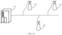
- FIG. 5-1 is a schematic structural diagram of a data dimension reduction system according to an embodiment of the present invention.
- FIG. 5-2 is a schematic structural diagram of another data dimension reduction system according to an embodiment of the present invention.
- FIG. 6-1 is a schematic structural diagram of a network device according to an embodiment of the present invention.
- FIG. 6-2 is a schematic diagram of an application program unit related to an embodiment shown in FIG. 6-1 .
- FIG. 1 is a schematic diagram of an implementation environment related to a data dimension reduction method according to an embodiment of the present invention.
- the implementation environment may include an. RCC 101 , at least one RRS 102 , and at least one user equipment (UE) 103 .
- the RRS 102 and the RCC 101 are base station devices.
- the RRS 102 and the RCC 101 are connected. by using a connection component such as an optical fiber,
- the RRS 102 is connected to an antenna by using a feeder, and communicates with the UE 103 by using the antenna.
- a conventional interface between a BBU and. an RRU is a CPRI.
- a BBU in a base station device in a 5G wireless network is redefined as an RCC
- an RRU is redefined as an RRS.
- an interface between the RCC and the RRS is defined as an eCPRI.
- the RRS 102 may receive, by using the antenna, an uplink signal sent by the UE 103 , preprocess the uplink signal, and transmit a preprocessed signal to the RCC 101 by using the eCPRI.
- LTE long term evolution
- uplink baseband processing and downlink baseband processing may be classified. into load-related user-level processing and load-unrelated cell-level processing.
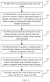
- Functions of the RRS and the RCC that are classified by using the eCPRI are shown in Table 1.
- the RRS implements signal sampling/recovery, resource mapping/demapping, and data dimension reduction processing.
- the RCC implements processing such as channel mapping and preceding, channel estimation and equalization, modulation/demodulation, bit-level processing, radio circuit control, and packet data convergence. “/” represents “or”.
- the signal sampling/recovery and the resource mapping/demapping are load-unrelated cell-level processing, and other processing is load-related user-level processing.
- the channel estimation and equalization are load-related user-level processing, and processing complexity of the channel estimation and equalization is positively correlated with a quantity of array antennas used for receiving a signal.
- the RRS may perform dimension reduction on a received uplink signal (that is, time domain data) to obtain a beam domain received signal (that is, frequency domain data), and transmit the beam domain received signal to the RCC by using the eCPRI.
- the RRS when dimensionally reducing the time domain data in antenna domain to the frequency domain data in beam domain, the RRS performs dimension reduction on the data by using a preset fixed beam domain weight. In other words, for different UEs, different quantities of UEs, and different scheduled bandwidths, dimension reduction is performed on data by using a same beam domain weight. Consequently, data dimension reduction has relatively low flexibility.
- an embodiment of the present invention provides a data dimension reduction method that can be applied to an RRS. As shown in FIG. 2 , the method may include the following steps.
- Step 201 The RRS receives an antenna domain received signal.
- the antenna domain received signal includes an uplink signal that is sent by UE and that is received by an array antenna corresponding to the RRS, the antenna domain received signal is a time domain signal, a dimension of the antenna domain received signal is N 1 , and N 1 is an integer greater than 1.
- One RRS may correspond to a plurality of antennas.
- the antenna domain received signal is uplink signals that are sent by all UEs in a cell and that are received by antennas in the cell managed by the RRS.
- the UE sends an uplink signal X, and a quantity of array antennas corresponding to the RRS is N 1 .
- a dimension of the antenna domain received signal is N 1 .
- H is a channel response matrix in antenna domain, the channel response matrix includes a channel response from each UE to an array antenna, K is a constant, and a quantity of rows of H is equal to N 1 .
- Step 202 The RRS obtains a received beam weight, where the received beam weight is determined based on channel information of the UE, and different received beam weights are determined based on different channel information.
- the RRS may obtain the received beam weight in a plurality of manners.
- the RRS directly obtains the received beam weight.
- the RRS obtains the channel information of the UE, and determines the received beam weight based on the channel information of the UE.
- an RCC obtains the received beam weight and delivers the received beam weight to the RRS.
- the RCC determines the received beam weight based on the channel information of the UE, and the RRS receives the received beam weight sent by the RCC.
- the received beam weight is determined by the RRS based on the channel information of the UE.
- a method for determining the received beam weight by the RCC based on the channel information of the UE refer to a method for determining the received beam weight by the RRS based on the channel information of the UE. Details are not described in this embodiment of the present invention.
- the RRS may obtain channel information of each UE based on a periodic sounding reference signal (SRS) sent to each UE, and determines the received beam weight based on the channel information of each UE.
- the RRS may obtain channel information of each UE based on a demodulation reference signal (DMRS) sent to each UE, and determines the received beam weight based on the channel information of each UE.
- SRS periodic sounding reference signal
- DMRS demodulation reference signal
- the RRS may determine the received beam weight based on the channel information of the UE and a criterion such as a criterion of maximizing received energy of a target signal, a criterion of maximizing a signal-to-noise ratio of a target signal, or a criterion of maximizing a signal-to-interference plus noise ratio of a target signal.
- a criterion such as a criterion of maximizing received energy of a target signal, a criterion of maximizing a signal-to-noise ratio of a target signal, or a criterion of maximizing a signal-to-interference plus noise ratio of a target signal.
- a method for determining, by the RRS, the received beam weight based on the channel information of the UE and the criterion of maximizing received energy of a target signal may include the following steps.
- the space division multiplexing means that different beams are formed in different UE directions by using an adaptive array antenna, and each beam may provide one UE with a unique user channel without interference of other UE.
- the channel information of all the UEs includes channel information from each UE to all antennas in the cell managed by the RRS.
- i is an integer, 1 ⁇ i ⁇ M, and a dimension of the received beam weight is N 2 ⁇ N 1 .
- a method for determining, by the RRS, the received beam weight based on the channel information of the UE and the criterion of maximizing a signal-to-interference plus noise ratio of a target signal may include the following steps.
- the channel information of all the UEs includes channel information from each UE to all antennas in a cell in which the UE is located.
- the received beam weight is an interference whitening weight
- the interference whitening weight is a weight for changing colored noise (that is, correlated interference on each antenna) into white noise.
- the interference covariance matrix is determined based on an interference signal of UE in another cell (that is, a cell managed by another RRS).
- a dimension of the received beam weight obtained based on the foregoing formula is N 2 ⁇ N 1 .
- the beam domain received signal is a frequency domain signal, a dimension of the beam domain received signal is N 2 , and 0 ⁇ N 2 ⁇ N 1 .
- the dimension of the antenna domain received signal Y is N 1
- the dimension of the received beam weight is N 2 ⁇ N 1 .
- FIG. 3-1 is a schematic diagram of a received beam according to an embodiment of the present invention.
- a beam domain received signal corresponding to an uplink signal transmitted by UE 1 is received by an adaptive received beam 1 .
- Dimension reduction is performed on the antenna domain received signal by using the received beam weight, to obtain the beam domain received signal.
- an adaptive received beam is determined by using the received beam weight, and a signal is received by using the adaptive received beam.
- the adaptive received beam is a beam used to receive the beam domain received signal.
- the RRS corresponds to N 1 antennas.
- the adaptive received beam includes N 2 antennas, and a dimension of an antenna domain received signal received by using the adaptive received beam is N 2 .
- the signal received by using the adaptive received beam is a beam domain received signal actually transmitted by the RRS to the RCC, so that dimension reduction on the antenna domain received signal is implemented.
- adaptive received beams may better form a directivity pattern based on different paths through which uplink signals of the UE are propagated in space. Different antenna gains are provided in different arrival directions, and a narrow beam is formed. in real time and is aligned with an uplink signal. In addition, in another direction, a side lobe is suppressed to a greatest extent, and directional receiving is used, so that a system capacity increases.
- an arrival direction of an uplink signal received by the RRS is time-varying.
- Signals that have close frequencies but that can be separated in space may be separated by using an adaptive received beam, and the signals are tracked to adjust a weight of an array antenna, so that a beam of the array antenna points to a direction of a target signal.
- a signal is received by using the adaptive received beam, so that a received beam direction is relatively accurate, or an interference suppression effect is relatively good.
- Frequency domain data of the adaptive received beam is transmitted to a baseband to perform channel estimation and equalization, to improve system coverage and a system capacity when an optical fiber capacity is limited.
- Step 204 The RRS determines a quantity of supplementary received beams based on the channel information of the UE or a priority of the UE.
- the supplementary received beam may be added based on the adaptive received beam.
- the supplementary received beam may be n fixed received beams having highest received energy in the cell, or the supplementary received beam may be n directional received beams that are predicted based on a multipath direction of a user channel and a moving direction, where n is a positive integer.
- the channel information of the UE includes a signal-to-noise ratio of the user channel, a moving speed of the UE, a spread angle of the UE, and a quantity of multipath directions of the user channel. For example, for UE with a large spread angle, energy is dispersed on a relatively large quantity of received beams, and a quantity of supplementary received beams may be increased to comprehensively receive the energy. For UE that is relatively strongly interfered by UE in another cell, a relatively large quantity of supplementary received beams may be added to ensure communication quality of the UE.
- transmission traffic of the eCPRI is determined by using a new radio bandwidth and a quantity of received beams.
- a quantity of supplementary received beams of the moving UE may be greater than a quantity of supplementary received beams of static UE.
- the quantity of supplementary received beams may be in positive correlation with the moving speed of the UE.
- a scheduled bandwidth on the eCPRI is not full, if an optical fiber capacity is fixed, more supplementary received beams may be allocated to a user in the scheduled bandwidth, to improve system coverage and a system capacity.
- different quantities of supplementary received beams may be allocated to different UEs in a limited optical fiber capacity, to optimize system performance.
- the priority of the UE may be determined based on a service type of the UE, whether a signal is retransmitted, or the like.
- the service type may include a home subscriber, an enterprise private line, a dedicated network service, and the like. Compared with that of UE of the home subscriber, a quantity of supplementary received beams of LIE of the dedicated network service is larger. (to be specific, a priority of the UE of the dedicated network service is higher than that of the UE of the home subscriber). A priority of UE that needs to retransmit a signal is higher than a priority of UE that initially transmits a signal.
- the quantity of supplementary received beams is adaptively adjusted, to increase received energy and improve a multi-antenna dimension, and frequency domain data received from the supplementary received beams is transmitted to the RRS for channel estimation and equalization, so that the system coverage and the system capacity can be improved when the optical fiber capacity is limited.
- Step 205 The RRS supplements the beam domain received signal with n target received beam signals, to obtain an updated beam domain received signal.
- An uplink signal transmitted by UE 1 may be received by the RRS separately by using the adaptive received beam 1 and the fixed received beam 2 .
- a signal received by the adaptive received beam 1 is a beam domain received signal
- a signal received by the fixed received beam 2 is a target received beam signal.
- the target received beam signals may alternatively be signals received by n directional supplementary received beams that are predicted based on the multipath direction of the user channel and the moving direction, where n is a positive integer.
- a method for predicting the n directional supplementary received beams based on the multipath direction of the user channel and the moving direction may include the following steps.
- d is a distance between the array antennas
- ⁇ is a wavelength of the received beam
- N 1 is a quantity of array antennas
- the arrival angle ⁇ is an angle between the UE and a normal line of the array antenna.
- a dimension of a signal received by each supplementary received beam is 1 ⁇ N 1
- Step 205 Adjust a data bit width of the eCPRI based on a preset measurement value.
- the preset measurement value may include measurement values such as signal-to-noise ratios or interference strength of different user channels or different UEs.
- a relatively small quantized data bit width may be used to represent an uplink signal sent by the UE.
- a data bit width of a bandwidth in which the UE is located is determined by using a signal-to-noise ratio of a scheduled user, so that transmission traffic of the eCPRI can be reduced. Therefore, more UEs can be scheduled when the transmission traffic of the eCPRI is limited.
- Step 206 The RRS transmits the beam domain received signal to the RCC by using the eCPRI.
- the RRS may transmit, to the RCC by using the eCPRI, the beam domain received signal in a bandwidth scheduled for a user.
- only frequency domain data (beam domain received information) in a bandwidth scheduled for the user may be transmitted to the RCC based on a scheduled bandwidth of the system at a current moment (in actual application, a system time is counted in a form of a frame) and an occupied bandwidth of a control channel. For example, if a bandwidth of the system at the current moment is 20M and the bandwidth scheduled for the user is 10M, the RRS may transmit, to the RCC, only the 10M of bandwidth scheduled for the user, so that a quantity of users who can be scheduled in the system can be ensured when a transmission bandwidth is limited.
- a resource allocation manner in a comb form may be used on a channel, in other words, resources are occupied at intervals.
- the resource allocation manner in the comb form may be used on a DMRS channel and an SRS channel.
- the RRS may adjust a frequency channel number of frequency domain data, and transmit only frequency domain data to which a resource is allocated.
- dimension reduction may be performed based on different dimension reduction targets and actual requirements such as a demodulation requirement and a performance requirement.
- dimensions reduction is performed based on different dimension reduction targets, directions and quantities of adaptive received beams are different, quantities of supplementary received beams are different, and data bit widths of bandwidths in which UE is located are different.
- the control channel has a higher requirement for stability of demodulation. Therefore, more supplementary received beams may be added for the control channel.
- the data dimension reduction method provided in this embodiment of the present invention can be applied to both an RRS in a centralized network architecture (that is, an architecture in which an RCC is deployed in a centralized manner) and an RRS in a distributed network architecture (that is, an architecture in which an RCC is deployed in a distributed manner).
- the RRS may determine the received beam weight based on the channel information of the UE, and perform dimension reduction on the received antenna domain received signal by using the received beam weight, to obtain the beam domain received signal. Because the different received beam weights are determined based on the different channel information, beam domain received signals obtained after dimension reduction is performed on different antenna domain received signals may have different dimensions, so that flexibility of data dimension reduction is improved.
- An embodiment of the present invention provides a data dimension reduction apparatus, applied to an RRS.
- the RRS is connected to an RCC by using an eCPRI.
- the apparatus 40 may include:
- a receiving module 401 configured to receive an antenna domain received signal, where the antenna domain received signal includes an uplink signal that is sent by user equipment UE and that is received by an array antenna corresponding to the RRS, the antenna domain received signal is a time domain signal, a dimension of the antenna domain received signal is N 1 , and N 1 is an integer greater than 1;
- an obtaining module 402 configured to obtain a received beam weight, where the received beam weight is determined based on channel information of the UE, and different received beam weights are determined based on different channel information;
- a dimension reduction module 403 configured to perform dimension reduction on the antenna domain received signal by using the received beam weight, to obtain a beam domain received signal, where the beam domain received signal is a frequency domain signal, a dimension of the beam domain received signal is N 2 , and 0 ⁇ N 2 ⁇ N 1 .
- the RRS may determine the received beam weight by using the obtaining module based on the channel information of the UE, and perform dimension reduction on the received antenna domain received signal by using the received beam weight and the dimension reduction module, to obtain the beam domain received signal. Because the different received beam weights are determined based on the different channel information, beam domain received signals obtained after dimension reduction is performed on different antenna domain received signals may have different dimensions, so that flexibility of data dimension reduction is improved.
- the obtaining module 402 may include:
- an obtaining submodule 4021 configured to obtain the channel information of the UE.
- a determining submodule 4022 configured to determine the received beam weight based on the channel information of the UE.
- the obtaining module may be configured to:
- the obtaining module may be configured to:
- the determining submodule may be configured to:
- the received beam weight based on the channel information of the UE and a criterion of maximizing received energy of a target signal.
- the determining submodule may be configured to:
- i is an integer, and 1 ⁇ i ⁇ M.
- the determining submodule may be configured to:
- the obtaining module may be alternatively configured to:
- the RCC receives the received beam weight sent by the RCC, where the received beam weight is determined by the RCC based on the channel information of the UE.
- the apparatus 40 may further include:
- a supplement module 404 configured to supplement the beam domain received signal with a target received beam signal, to obtain an updated beam domain received signal, where the target received beam signal is a signal received by n supplementary received beams in a preset fixed direction, or the target received beam signal is a signal received by n directional supplementary received beams that are predicted based on a multipath direction of a user channel and a moving direction, and n is a positive integer.
- the supplement module may be configured to: determine that a supplementary beam weight of a received beam whose arrival angle is ⁇ is
- W ⁇ [ 1 , e - j ⁇ 2 ⁇ ⁇ ⁇ ⁇ d ⁇ ⁇ sin ⁇ ⁇ ⁇ , ... ⁇ , e - j ⁇ 2 ⁇ ⁇ ⁇ ⁇ ( N 1 - 1 ) ⁇ d ⁇ ⁇ sin ⁇ ⁇ ⁇ ] , where d is a distance between the array antennas, ⁇ is a wavelength of the received beam, and N 1 is a quantity of array antennas;
- W supplement [W ⁇ 1 , W ⁇ 2 , . . . , W ⁇ n ] ⁇ 1 ;
- the apparatus 40 may further include:
- a determining module 405 configured to determine a quantity of supplementary received beams based on the channel information of the UE or a priority of the UE.
- the channel information of the UE may include a signal-to-noise ratio of the user channel, a moving speed of the UE, a spread angle of the UE, and a quantity of multipaths of the user channel.
- the priority of the UE may be determined based on a service type of the UE.
- the apparatus 40 may further include:
- an adjustment module 406 configured to adjust a data bit width of the eCPRI based on a preset measurement value
- a transmission module 407 configured to transmit the beam domain received signal to the RCC by using the eCPRI.
- the transmission module 407 may be configured to:
- the RRS may determine the received beam weight by using the obtaining module based on the channel information of the UE, and perform dimension reduction on the received antenna domain received signal by using the received beam weight and the dimension reduction module, to obtain the beam domain received signal. Because the different received beam weights are determined based on the different channel information, beam domain received signals obtained after dimension reduction is performed on different antenna domain received signals may have different dimensions, so that flexibility of data dimension reduction is improved.
- An embodiment of the present invention provides a data dimension reduction system.
- the system may include an RCC and a plurality of RRSs, at least one RRS includes the apparatus 40 shown in any one of FIG. 4-1 and FIG. 4-3 to FIG. 4-5 , and the plurality of RRSs are connected to the RCC by using a common public radio interface eCPRI.
- eCPRI public radio interface
- the plurality of RRSs 102 are connected to the RCC 101 in a cascading manner by using an optical fiber.
- the plurality of RRSs need to use a same optical fiber to transmit beam domain received signals to the RCC. To ensure that data on each RRS can be effectively transmitted to the RCC, each RRS needs to perform dimension reduction on a received antenna domain received signal according to the foregoing data dimension reduction method based on total traffic of the data that needs to be transmitted by the plurality of RRSs.
- the plurality of RRSs 102 are connected to the RCC 101 in a star connection manner by using an optical fiber.
- each RRS is connected to a base station device by using an optical fiber whose bandwidth is 25 G. After a plurality of optical fibers corresponding to the plurality of RRSs are converged on the base station device, data that needs to be transmitted by each RRS may be transmitted to the RCC by using an optical fiber whose bandwidth is 30 G. Because the data that needs to be transmitted by the plurality of RRSs finally needs to be transmitted to the RCC by using the optical fiber whose bandwidth is 30 G, each RRS needs to be constrained by the optical fiber whose bandwidth is 30 G, and dimension reduction is performed on the received antenna domain received signal according to the foregoing data dimension reduction method based on the total traffic of the data that needs to be transmitted by the plurality of RRSs.
- the RRS may determine a received beam weight by using an obtaining module based on channel information of UE, and perform dimension reduction on the received antenna domain received signal by using the received beam weight and a dimension reduction module, to obtain a beam domain received signal. Because different received beam weights are determined based on different channel information, beam domain received signals obtained after dimension reduction is performed on different antenna domain received signals may have different dimensions, so that flexibility of data dimension reduction is improved.
- FIG. 6-1 is a schematic structural diagram of a network device according to an example embodiment of the present invention.
- the network device 10 may be the RCC 101 , the RRS 102 , or the UE 103 , and the network device 10 includes a processor 12 and a network interface 14 .
- the processor 12 includes one or more processing cores.
- the processor 12 implements various functional applications and data processing by running a software program and a unit.
- the network interface 14 is configured to communicate with another storage device or network device.
- the network device 10 further includes components such as a memory 16 and a bus 18 .
- the memory 16 and the network interface 14 are separately connected to the processor 12 by using the bus 18 ,
- the memory 16 may be configured to store the software program and the unit. Specifically, the memory 16 may store an operating system 162 and an application program unit 164 required for at least one function.
- the operating system 162 may be an operating system such as a real-time operating system (RTX), LINUX, UNIX, WINDOWS, or OS X.
- FIG. 6-2 is a schematic diagram of an application program unit related to an embodiment shown in FIG. 6-1 .
- the application program unit 164 may be a receiving unit 164 a , an obtaining unit 164 b , and a dimension reduction unit 164 c.
- the receiving unit 164 a has a function the same as or similar to that of the receiving module 401 .
- the obtaining unit 164 b has a function the same as or similar to that of the obtaining module 402 .
- the dimension reduction unit 164 c has a function the same as or similar to that of the dimension reduction module 403 .
- the program may be stored in a computer-readable storage medium.
- the storage medium may be a read-only memory, a magnetic disk, an optical disc, or the like.
Abstract
Description
where
where d is a distance between the array antennas, λ is a wavelength of the received beam, and N1 is a quantity of array antennas;
| TABLE 1 | ||
| Downlink | Uplink | |
| RRS | Resource mapping and | Signal sampling and resource |
| signal recovery | demapping | |
| Data dimension reduction processing | ||
| RCC | Channel mapping and | Channel estimation and equalization |
| precoding | ||
| Modulation | Demodulation | |
| Bit-level processing | Bit-level processing | |
| Radio circuit control | Radio circuit control | |
| Packet data convergence | Packet data convergence | |
where
where d is a distance between the array antennas, λ is a wavelength of the received beam, and N1 is a quantity of array antennas;
Claims (19)
Applications Claiming Priority (1)
| Application Number | Priority Date | Filing Date | Title |
|---|---|---|---|
| PCT/CN2017/094908 WO2019019149A1 (en) | 2017-07-28 | 2017-07-28 | Data dimension reduction method, device and system, computer device, and storage medium |
Related Parent Applications (1)
| Application Number | Title | Priority Date | Filing Date |
|---|---|---|---|
| PCT/CN2017/094908 Continuation WO2019019149A1 (en) | 2017-07-28 | 2017-07-28 | Data dimension reduction method, device and system, computer device, and storage medium |
Publications (2)
| Publication Number | Publication Date |
|---|---|
| US20200162940A1 US20200162940A1 (en) | 2020-05-21 |
| US11234294B2 true US11234294B2 (en) | 2022-01-25 |
Family
ID=65039345
Family Applications (1)
| Application Number | Title | Priority Date | Filing Date |
|---|---|---|---|
| US16/749,103 Active 2037-10-15 US11234294B2 (en) | 2017-07-28 | 2020-01-22 | Data dimension reduction method, apparatus, and system, computer device, and storage medium |
Country Status (4)
| Country | Link |
|---|---|
| US (1) | US11234294B2 (en) |
| EP (1) | EP3641487B1 (en) |
| CN (1) | CN110832949B (en) |
| WO (1) | WO2019019149A1 (en) |
Families Citing this family (2)
| Publication number | Priority date | Publication date | Assignee | Title |
|---|---|---|---|---|
| CN114070514B (en) * | 2020-08-06 | 2023-03-14 | 大唐移动通信设备有限公司 | Control information receiving processing method and device, electronic equipment and storage medium |
| CN114080032A (en) * | 2020-08-14 | 2022-02-22 | 大唐移动通信设备有限公司 | Resource multiplexing method, network equipment, device and storage medium of multi-antenna system |
Citations (17)
| Publication number | Priority date | Publication date | Assignee | Title |
|---|---|---|---|---|
| CN101753181A (en) | 2008-12-12 | 2010-06-23 | 大唐移动通信设备有限公司 | Data transmission method, system and device |
| WO2011074031A1 (en) | 2009-12-16 | 2011-06-23 | 株式会社 東芝 | Wireless signal processing device and wireless device |
| US20110241939A1 (en) * | 2010-03-30 | 2011-10-06 | Maenpa Jon E | System and method for frequency domain correction of global navigation satellite system pseudorance measurements in receivers having controlled reception pattern antennas |
| CN102291855A (en) | 2010-06-18 | 2011-12-21 | 普天信息技术研究院有限公司 | Method for reducing infrared ray (Ir) interface bandwidth and distributive base station |
| CN102299735A (en) | 2010-06-25 | 2011-12-28 | 普天信息技术研究院有限公司 | Method for decreasing bandwidth of Ir interface and distributed base station |
| CN102801681A (en) | 2012-08-01 | 2012-11-28 | 大唐移动通信设备有限公司 | Data transmission method and distributed base station |
| US20130120191A1 (en) * | 2011-11-11 | 2013-05-16 | Telefonaktiebolaget L M Ericsson (Publ) | Method, Apparatus and System of Antenna Array Dynamic Configuration |
| CN103457647A (en) | 2012-06-04 | 2013-12-18 | 普天信息技术研究院有限公司 | Method and device for shaping double-flow wave beams |
| CN103475613A (en) | 2012-06-06 | 2013-12-25 | 中兴通讯股份有限公司 | Signal sending and receiving method and relevant equipment |
| JP2014204218A (en) | 2013-04-03 | 2014-10-27 | 日本電信電話株式会社 | Base station system, base station communication method, and baseband unit |
| US20160028453A1 (en) * | 2013-12-31 | 2016-01-28 | Spreadtrum Communications (Shanghai) Co., Ltd. | Ofdm communication system, method and device for transceiving signal |
| WO2017107016A1 (en) | 2015-12-21 | 2017-06-29 | 华为技术有限公司 | Data transmission method, remote radio unit (rru) and baseband unit (bbu) |
| US20170237831A1 (en) * | 2016-02-16 | 2017-08-17 | Nokia Solutions And Networks Oy | Compressing/decompressing frequency domain signals |
| US20180159611A1 (en) * | 2016-12-02 | 2018-06-07 | At&T Intellectual Property I, L.P. | Facilitation of physical layer design for 5g networks or other next generation networks |
| US20180217838A1 (en) * | 2017-02-01 | 2018-08-02 | Futurewei Technologies, Inc. | Ultra lean vector processor |
| US20190335474A1 (en) * | 2017-01-06 | 2019-10-31 | Huawei Technologies Co., Ltd | Information indication method, network device, and terminal device |
| US20200274558A1 (en) * | 2015-12-28 | 2020-08-27 | China Academy Of Telecommunications Technology | Method and apparatus for signal processing |
-
2017
- 2017-07-28 CN CN201780092805.5A patent/CN110832949B/en active Active
- 2017-07-28 WO PCT/CN2017/094908 patent/WO2019019149A1/en unknown
- 2017-07-28 EP EP17919614.2A patent/EP3641487B1/en active Active
-
2020
- 2020-01-22 US US16/749,103 patent/US11234294B2/en active Active
Patent Citations (19)
| Publication number | Priority date | Publication date | Assignee | Title |
|---|---|---|---|---|
| CN101753181A (en) | 2008-12-12 | 2010-06-23 | 大唐移动通信设备有限公司 | Data transmission method, system and device |
| WO2011074031A1 (en) | 2009-12-16 | 2011-06-23 | 株式会社 東芝 | Wireless signal processing device and wireless device |
| US20120252366A1 (en) | 2009-12-16 | 2012-10-04 | Kabushiki Kaisha Toshiba | Wireless signal processor and wireless apparatus |
| US20110241939A1 (en) * | 2010-03-30 | 2011-10-06 | Maenpa Jon E | System and method for frequency domain correction of global navigation satellite system pseudorance measurements in receivers having controlled reception pattern antennas |
| CN102291855A (en) | 2010-06-18 | 2011-12-21 | 普天信息技术研究院有限公司 | Method for reducing infrared ray (Ir) interface bandwidth and distributive base station |
| CN102299735A (en) | 2010-06-25 | 2011-12-28 | 普天信息技术研究院有限公司 | Method for decreasing bandwidth of Ir interface and distributed base station |
| US20130120191A1 (en) * | 2011-11-11 | 2013-05-16 | Telefonaktiebolaget L M Ericsson (Publ) | Method, Apparatus and System of Antenna Array Dynamic Configuration |
| CN103457647A (en) | 2012-06-04 | 2013-12-18 | 普天信息技术研究院有限公司 | Method and device for shaping double-flow wave beams |
| CN103475613A (en) | 2012-06-06 | 2013-12-25 | 中兴通讯股份有限公司 | Signal sending and receiving method and relevant equipment |
| CN102801681A (en) | 2012-08-01 | 2012-11-28 | 大唐移动通信设备有限公司 | Data transmission method and distributed base station |
| JP2014204218A (en) | 2013-04-03 | 2014-10-27 | 日本電信電話株式会社 | Base station system, base station communication method, and baseband unit |
| US20160028453A1 (en) * | 2013-12-31 | 2016-01-28 | Spreadtrum Communications (Shanghai) Co., Ltd. | Ofdm communication system, method and device for transceiving signal |
| WO2017107016A1 (en) | 2015-12-21 | 2017-06-29 | 华为技术有限公司 | Data transmission method, remote radio unit (rru) and baseband unit (bbu) |
| US20180138957A1 (en) | 2015-12-21 | 2018-05-17 | Huawei Technologies Co., Ltd. | Data transmission method, remote radio unit rru, and baseband unit bbu |
| US20200274558A1 (en) * | 2015-12-28 | 2020-08-27 | China Academy Of Telecommunications Technology | Method and apparatus for signal processing |
| US20170237831A1 (en) * | 2016-02-16 | 2017-08-17 | Nokia Solutions And Networks Oy | Compressing/decompressing frequency domain signals |
| US20180159611A1 (en) * | 2016-12-02 | 2018-06-07 | At&T Intellectual Property I, L.P. | Facilitation of physical layer design for 5g networks or other next generation networks |
| US20190335474A1 (en) * | 2017-01-06 | 2019-10-31 | Huawei Technologies Co., Ltd | Information indication method, network device, and terminal device |
| US20180217838A1 (en) * | 2017-02-01 | 2018-08-02 | Futurewei Technologies, Inc. | Ultra lean vector processor |
Non-Patent Citations (3)
| Title |
|---|
| Extended European Search Report issued in European Application No. 17919614.2 dated Mar. 27, 2020, 8 pages. |
| Office Action issued in Chinese Application No. 201780092805.5 dated Dec. 29, 2020, 6 pages. |
| PCT International Search Report and Written Opinion issued in International Application No. PCT/CN2017/094908 dated Apr. 18, 2018, 16 pages (with English translation). |
Also Published As
| Publication number | Publication date |
|---|---|
| CN110832949A (en) | 2020-02-21 |
| EP3641487B1 (en) | 2022-07-06 |
| WO2019019149A1 (en) | 2019-01-31 |
| EP3641487A4 (en) | 2020-04-29 |
| EP3641487A1 (en) | 2020-04-22 |
| CN110832949B (en) | 2021-08-20 |
| US20200162940A1 (en) | 2020-05-21 |
Similar Documents
| Publication | Publication Date | Title |
|---|---|---|
| KR102481397B1 (en) | Sounding reference signal power control for multiple input multiple output wireless system | |
| US10841057B2 (en) | Systems and methods for UE-specific beam management for high frequency wireless communication | |
| JP5963889B2 (en) | Virtual sectorization using active antenna arrays | |
| US10727917B2 (en) | Beamforming of beams | |
| AU2022215154A1 (en) | Systems and methods for mitigating interference within actively used spectrum | |
| US11234294B2 (en) | Data dimension reduction method, apparatus, and system, computer device, and storage medium | |
| US20220104233A1 (en) | Frequency adjustment in wireless transmission and reception | |
| US9020554B2 (en) | System and method for supporting multi-user antenna beamforming in a cellular network | |
| US10177955B2 (en) | In and relating to communication network resourcing | |
| EP4032193B1 (en) | Simultaneous uplink and downlink transmission using multiple access points | |
| WO2023124959A1 (en) | Interference avoidance method, apparatus, and system | |
| US20220166474A1 (en) | Systems and methods for mitigating interference within actively used spectrum | |
| Holma et al. | 5G Performance | |
| EP3504891B1 (en) | Systems and methods for mitigating interference within actively used spectrum | |
| KR20210060339A (en) | Apparatus and method for clustrering in communication network | |
| KR20210060308A (en) | Method for transmitting ultra reliable low latency communication traffic in communication network | |
| CN114600382A (en) | Beam alignment | |
| NZ791129A (en) | Systems and methods for mitigating interference within actively used spectrum |
Legal Events
| Date | Code | Title | Description |
|---|---|---|---|
| FEPP | Fee payment procedure |
Free format text: ENTITY STATUS SET TO UNDISCOUNTED (ORIGINAL EVENT CODE: BIG.); ENTITY STATUS OF PATENT OWNER: LARGE ENTITY |
|
| STPP | Information on status: patent application and granting procedure in general |
Free format text: DOCKETED NEW CASE - READY FOR EXAMINATION |
|
| AS | Assignment |
Owner name: HUAWEI TECHNOLOGIES CO., LTD., CHINA Free format text: ASSIGNMENT OF ASSIGNORS INTEREST;ASSIGNORS:GAO, QUANZHONG;XU, HENG;LIU, GUOCHEN;AND OTHERS;SIGNING DATES FROM 20200525 TO 20210130;REEL/FRAME:055098/0604 |
|
| STPP | Information on status: patent application and granting procedure in general |
Free format text: NON FINAL ACTION MAILED |
|
| STPP | Information on status: patent application and granting procedure in general |
Free format text: RESPONSE TO NON-FINAL OFFICE ACTION ENTERED AND FORWARDED TO EXAMINER |
|
| STPP | Information on status: patent application and granting procedure in general |
Free format text: NOTICE OF ALLOWANCE MAILED -- APPLICATION RECEIVED IN OFFICE OF PUBLICATIONS |
|
| STPP | Information on status: patent application and granting procedure in general |
Free format text: PUBLICATIONS -- ISSUE FEE PAYMENT VERIFIED |
|
| STCF | Information on status: patent grant |
Free format text: PATENTED CASE |