US11233463B2 - Modular multilevel converter - Google Patents
Modular multilevel converter Download PDFInfo
- Publication number
- US11233463B2 US11233463B2 US16/965,296 US201816965296A US11233463B2 US 11233463 B2 US11233463 B2 US 11233463B2 US 201816965296 A US201816965296 A US 201816965296A US 11233463 B2 US11233463 B2 US 11233463B2
- Authority
- US
- United States
- Prior art keywords
- converter
- converter arm
- arm
- voltage
- cells
- Prior art date
- Legal status (The legal status is an assumption and is not a legal conclusion. Google has not performed a legal analysis and makes no representation as to the accuracy of the status listed.)
- Active
Links
Images


Classifications
-
- H—ELECTRICITY
- H02—GENERATION; CONVERSION OR DISTRIBUTION OF ELECTRIC POWER
- H02M—APPARATUS FOR CONVERSION BETWEEN AC AND AC, BETWEEN AC AND DC, OR BETWEEN DC AND DC, AND FOR USE WITH MAINS OR SIMILAR POWER SUPPLY SYSTEMS; CONVERSION OF DC OR AC INPUT POWER INTO SURGE OUTPUT POWER; CONTROL OR REGULATION THEREOF
- H02M7/00—Conversion of ac power input into dc power output; Conversion of dc power input into ac power output
- H02M7/42—Conversion of dc power input into ac power output without possibility of reversal
- H02M7/44—Conversion of dc power input into ac power output without possibility of reversal by static converters
- H02M7/48—Conversion of dc power input into ac power output without possibility of reversal by static converters using discharge tubes with control electrode or semiconductor devices with control electrode
- H02M7/483—Converters with outputs that each can have more than two voltages levels
-
- H—ELECTRICITY
- H02—GENERATION; CONVERSION OR DISTRIBUTION OF ELECTRIC POWER
- H02M—APPARATUS FOR CONVERSION BETWEEN AC AND AC, BETWEEN AC AND DC, OR BETWEEN DC AND DC, AND FOR USE WITH MAINS OR SIMILAR POWER SUPPLY SYSTEMS; CONVERSION OF DC OR AC INPUT POWER INTO SURGE OUTPUT POWER; CONTROL OR REGULATION THEREOF
- H02M1/00—Details of apparatus for conversion
-
- H—ELECTRICITY
- H02—GENERATION; CONVERSION OR DISTRIBUTION OF ELECTRIC POWER
- H02M—APPARATUS FOR CONVERSION BETWEEN AC AND AC, BETWEEN AC AND DC, OR BETWEEN DC AND DC, AND FOR USE WITH MAINS OR SIMILAR POWER SUPPLY SYSTEMS; CONVERSION OF DC OR AC INPUT POWER INTO SURGE OUTPUT POWER; CONTROL OR REGULATION THEREOF
- H02M7/00—Conversion of ac power input into dc power output; Conversion of dc power input into ac power output
- H02M7/42—Conversion of dc power input into ac power output without possibility of reversal
- H02M7/44—Conversion of dc power input into ac power output without possibility of reversal by static converters
- H02M7/48—Conversion of dc power input into ac power output without possibility of reversal by static converters using discharge tubes with control electrode or semiconductor devices with control electrode
- H02M7/483—Converters with outputs that each can have more than two voltages levels
- H02M7/4835—Converters with outputs that each can have more than two voltages levels comprising two or more cells, each including a switchable capacitor, the capacitors having a nominal charge voltage which corresponds to a given fraction of the input voltage, and the capacitors being selectively connected in series to determine the instantaneous output voltage
-
- H—ELECTRICITY
- H02—GENERATION; CONVERSION OR DISTRIBUTION OF ELECTRIC POWER
- H02M—APPARATUS FOR CONVERSION BETWEEN AC AND AC, BETWEEN AC AND DC, OR BETWEEN DC AND DC, AND FOR USE WITH MAINS OR SIMILAR POWER SUPPLY SYSTEMS; CONVERSION OF DC OR AC INPUT POWER INTO SURGE OUTPUT POWER; CONTROL OR REGULATION THEREOF
- H02M7/00—Conversion of ac power input into dc power output; Conversion of dc power input into ac power output
- H02M7/42—Conversion of dc power input into ac power output without possibility of reversal
- H02M7/44—Conversion of dc power input into ac power output without possibility of reversal by static converters
- H02M7/48—Conversion of dc power input into ac power output without possibility of reversal by static converters using discharge tubes with control electrode or semiconductor devices with control electrode
- H02M7/483—Converters with outputs that each can have more than two voltages levels
- H02M7/4837—Flying capacitor converters
-
- H—ELECTRICITY
- H02—GENERATION; CONVERSION OR DISTRIBUTION OF ELECTRIC POWER
- H02M—APPARATUS FOR CONVERSION BETWEEN AC AND AC, BETWEEN AC AND DC, OR BETWEEN DC AND DC, AND FOR USE WITH MAINS OR SIMILAR POWER SUPPLY SYSTEMS; CONVERSION OF DC OR AC INPUT POWER INTO SURGE OUTPUT POWER; CONTROL OR REGULATION THEREOF
- H02M7/00—Conversion of ac power input into dc power output; Conversion of dc power input into ac power output
- H02M7/42—Conversion of dc power input into ac power output without possibility of reversal
- H02M7/44—Conversion of dc power input into ac power output without possibility of reversal by static converters
- H02M7/48—Conversion of dc power input into ac power output without possibility of reversal by static converters using discharge tubes with control electrode or semiconductor devices with control electrode
- H02M7/53—Conversion of dc power input into ac power output without possibility of reversal by static converters using discharge tubes with control electrode or semiconductor devices with control electrode using devices of a triode or transistor type requiring continuous application of a control signal
- H02M7/537—Conversion of dc power input into ac power output without possibility of reversal by static converters using discharge tubes with control electrode or semiconductor devices with control electrode using devices of a triode or transistor type requiring continuous application of a control signal using semiconductor devices only, e.g. single switched pulse inverters
- H02M7/5387—Conversion of dc power input into ac power output without possibility of reversal by static converters using discharge tubes with control electrode or semiconductor devices with control electrode using devices of a triode or transistor type requiring continuous application of a control signal using semiconductor devices only, e.g. single switched pulse inverters in a bridge configuration
- H02M7/53871—Conversion of dc power input into ac power output without possibility of reversal by static converters using discharge tubes with control electrode or semiconductor devices with control electrode using devices of a triode or transistor type requiring continuous application of a control signal using semiconductor devices only, e.g. single switched pulse inverters in a bridge configuration with automatic control of output voltage or current
-
- H—ELECTRICITY
- H02—GENERATION; CONVERSION OR DISTRIBUTION OF ELECTRIC POWER
- H02M—APPARATUS FOR CONVERSION BETWEEN AC AND AC, BETWEEN AC AND DC, OR BETWEEN DC AND DC, AND FOR USE WITH MAINS OR SIMILAR POWER SUPPLY SYSTEMS; CONVERSION OF DC OR AC INPUT POWER INTO SURGE OUTPUT POWER; CONTROL OR REGULATION THEREOF
- H02M1/00—Details of apparatus for conversion
- H02M1/0048—Circuits or arrangements for reducing losses
- H02M1/0054—Transistor switching losses
-
- H—ELECTRICITY
- H02—GENERATION; CONVERSION OR DISTRIBUTION OF ELECTRIC POWER
- H02M—APPARATUS FOR CONVERSION BETWEEN AC AND AC, BETWEEN AC AND DC, OR BETWEEN DC AND DC, AND FOR USE WITH MAINS OR SIMILAR POWER SUPPLY SYSTEMS; CONVERSION OF DC OR AC INPUT POWER INTO SURGE OUTPUT POWER; CONTROL OR REGULATION THEREOF
- H02M1/00—Details of apparatus for conversion
- H02M1/0095—Hybrid converter topologies, e.g. NPC mixed with flying capacitor, thyristor converter mixed with MMC or charge pump mixed with buck
-
- Y—GENERAL TAGGING OF NEW TECHNOLOGICAL DEVELOPMENTS; GENERAL TAGGING OF CROSS-SECTIONAL TECHNOLOGIES SPANNING OVER SEVERAL SECTIONS OF THE IPC; TECHNICAL SUBJECTS COVERED BY FORMER USPC CROSS-REFERENCE ART COLLECTIONS [XRACs] AND DIGESTS
- Y02—TECHNOLOGIES OR APPLICATIONS FOR MITIGATION OR ADAPTATION AGAINST CLIMATE CHANGE
- Y02B—CLIMATE CHANGE MITIGATION TECHNOLOGIES RELATED TO BUILDINGS, e.g. HOUSING, HOUSE APPLIANCES OR RELATED END-USER APPLICATIONS
- Y02B70/00—Technologies for an efficient end-user side electric power management and consumption
- Y02B70/10—Technologies improving the efficiency by using switched-mode power supplies [SMPS], i.e. efficient power electronics conversion e.g. power factor correction or reduction of losses in power supplies or efficient standby modes
Definitions
- the present disclosure relates to converters.
- Various embodiments include modular multilevel converters and/or methods of operation for the modular multilevel converter.
- Modular multilevel converters are a comparatively recent and attractive solution for power conversion without transformers. Some of their advantages are a high scalability, lesser or no need for AC filters and lesser or no need for DC link capacitors at the DC bus.
- a disadvantage of MMC is their high complexity which comes from the high number of individual converter cells and the associated switch control and capacitor charge balancing.
- some embodiments of the present disclosure include a modular multilevel converter ( 300 , 400 ) for converting between a DC voltage and an AC voltage, the modular multilevel converter ( 300 , 400 ) comprising: at least two phase units ( 102 , 202 ) connected in parallel and connectable to a DC terminal, the phase units ( 102 , 202 ) each comprising an upper converter arm ( 108 ) and a lower converter arm ( 112 ), each converter arm ( 108 , 112 ) having one or more cells (C, CF, CH) being arranged in series, wherein each cell (C, CF, CH) comprises an energy storage element (CP) and a switching arrangement adapted to switching the energy storage element (CP) in or out of the series of cells (C, CF, CH), a control unit being adapted to control the switching arrangements of the cells (C, CF, CH), a middle converter arm ( 110 ) arranged in series between the upper and lower
- each of the bridging elements ( 118 , 124 ) has a voltage rating equal to or higher than that of the middle converter arm ( 110 ).
- the energy storage elements (CP) are capacitors (CP) and the capacitors (CP) in the middle converter arm ( 110 ) have a smaller capacity than the capacitors (CP) of the lower or upper converter arm ( 108 , 112 ).
- the voltage rating of the middle, upper and lower converter arm ( 108 , 110 , 112 ) are equal.
- the voltage rating of the middle converter arm ( 110 ) is lower than the voltage rating of the upper and/or lower converter arm ( 108 , 112 ).
- the bridging elements ( 118 , 124 ) each comprise one or more switches ( 802 ) that are optimized for low conduction losses.
- the bridging elements each comprise one or more thyristors with reverse diodes.
- the cells (C, CF, CH) of the upper and lower converter arm ( 108 , 112 ) are full-bridge type cells (CF) and the cells of the middle converter arm ( 110 ) are half-bridge type cells (CH).
- phase units there are three or more of said phase units ( 102 , 202 ) being arranged in parallel.
- a second upper bridging element ( 218 ) arranged between said upper node ( 116 ) and an AC terminal ( 120 ), and a second lower bridging element ( 224 ) arranged between said lower node ( 122 ) and said AC terminal ( 120 ).
- first disconnector ( 206 ) between the middle point ( 204 ) of the upper and lower bridging element ( 118 , 124 ) and the AC terminal ( 120 ) and a second disconnector ( 210 ) between the middle point ( 208 ) of the second upper and lower bridging element ( 218 , 224 ) and the AC terminal ( 120 ).
- some embodiments include a method for operating the modular multilevel converter ( 300 , 400 ) as described herein, wherein the phase units ( 102 , 202 ) are connected to a DC network and the AC terminals ( 120 ) of the phase units are connected to an AC network, the control unit controls the switching arrangements of the cells (C, CF, CH) of the upper and lower converter arm ( 108 , 112 ) to adapt the voltage of the upper and lower converter arm ( 108 , 112 ) to the AC voltage level and the control unit controls the bridging elements ( 118 , 124 ) by turning on the upper bridging element ( 118 ) when the lower converter arm ( 112 ) voltage is higher than the upper converter arm ( 108 ) voltage, and turning on the lower bridging element ( 124 ) when the lower converter arm ( 112 ) voltage is lower than the upper converter arm ( 108 ) voltage.
- control unit switches the bridging elements ( 118 , 124 ) with a frequency that is twice the AC voltage frequency.
- control unit controls the switching arrangements of the cells (C, CF, CH) of the middle converter arm ( 110 ) such that the individual switches (H 1 a , H 1 b , H 2 a , H 2 b ) are turned on and/or off when their voltage is zero.
- FIG. 1 illustrates a modular multilevel converter according to the prior art
- FIGS. 2 and 3 illustrate examples of converter cells incorporating teachings of the present disclosure
- FIG. 4 illustrates a phase unit of a modular multilevel converter incorporating teachings of the present disclosure
- FIG. 5 illustrates a second phase unit of a modular multilevel converter incorporating teachings of the present disclosure
- FIG. 6 illustrates a single phase modular multilevel converter incorporating teachings of the present disclosure
- FIG. 7 illustrates a three phase modular multilevel converter incorporating teachings of the present disclosure.
- FIGS. 8-10 illustrate examples of bridging elements of the phase units of FIGS. 4 and 5 and of modular multilevel converters of FIGS. 6 and 7 .
- a modular multilevel converter for converting between a DC voltage and an AC voltage comprises at least two phase units connected in parallel and connectable to a DC terminal, the phase units each comprising an upper converter arm and a lower converter arm, each converter arm having one or more cells being arranged in series, wherein each cell comprises an energy storage element and a switching arrangement adapted to switching the energy storage element in or out of the series of cells.
- the modular multilevel converter comprises a control unit adapted to control the switching arrangements of the cells.
- the modular multilevel converter comprises a middle converter arm arranged in series between the upper and lower converter arm, the middle converter arm having a one or more cells being arranged in series, an upper node between said upper and middle converter arm and a lower node between said lower and middle converter arm, an upper bridging element arranged between said upper node and an AC terminal and a lower bridging current control arranged between said lower node and said AC terminal.
- the middle converter arm can be used to either support the lower converter arm or the upper converter arm, depending on the AC voltage. In that way the number of cells required for a given DC link voltage can be reduced by 25%.
- the middle converter arm supports both the upper and lower converter arm and the resulting current ripple has twice the frequency of the current ripple in the upper and lower converter arm. Because of the increased frequency the cell capacitors of the middle converter arm can be reduced in size without affecting the ripple current.
- some embodiments include a method for operating the modular multilevel converter, wherein the phase units are connected to a DC network and the AC terminals of the phase units are connected to an AC network, the control unit controls the switching arrangements of the cells of the upper and lower converter arm to adapt the voltage of the upper and lower converter arm to the AC voltage level and the control unit controls the bridging elements by turning on the upper bridging element when the lower converter arm voltage is higher than the upper converter arm voltage, and turning on the lower bridging element when the lower converter arm voltage is lower than the upper converter arm voltage.
- FIG. 1 illustrates a basic setup of a modular multilevel converter M for converting a DC voltage into an AC voltage or vice versa according to the prior art.
- FIG. 1 shows a single-phase unit A of the modular multilevel converter M.
- the phase unit A is connected to a DC line with DC terminals E 1 , E 2 and has an AC terminal A 1 .
- the number of phase units A used in actual embodiments of such a modular multilevel converter M can be one, two, three, or more. If the modular multilevel converter M comprises a plurality of phase units A these are typically arranged in parallel, i.e. the phase units A are each connected to the same DC line while their individual AC terminals A 1 form the AC phase terminals.
- Each phase unit A comprises an upper converter arm Z 1 and a lower converter arm Z 2 , each converter arm Z 1 , Z 2 having a plurality of two-terminal cells C being arranged in series.
- each converter arm Z 1 , Z 2 comprises an inductive element in the form of coils LI, L 2 in series with the series of cells C.
- the converter arms Z 1 , Z 2 in turn are connected in series between the DC terminals El, E 2 .
- the cells C comprise an energy storage element and a switching arrangement.
- the energy storage element is usually a capacitor.
- the switching arrangement enables the cell C to either short-circuit its two terminals, bypassing the energy storage, or place the energy storage element between its two terminals.
- the modular multilevel converter M further comprises a control unit adapted to control the cells C of the phase units A to convert between the DC terminals El, E 2 and the AC terminals A 1 .
- each cell C is adapted to generate a voltage step by charging its energy storage with the respective input voltage or from outside sources.
- the control unit is adapted to switch on part of the cells of one phase unit and to bypass the remainder of the cells of a phase unit A such that the sum of the voltage of the activated cells in the phase unit is equal to the direct current voltage.
- the ratio of activated cells C between the upper and lower converter arm Z 1 , Z 2 sets the voltage at the AC terminal A 1 of the phase unit. Varying the ratio in a sinusoidal manner may create a relatively smooth AC voltage at AC terminal A 1 .
- FIG. 2 shows an exemplary cell CH incorporating teachings of the present disclosure.
- Cell CH is a half-bridge cell. It comprises a half-bridge HI of two serially connected switches H 1 a , H 1 b .
- the switches H 1 a , H 1 b may be IGBTs or other kinds of semiconductor switches.
- a capacitor CP is arranged in parallel to the half-bridge HI.
- a first terminal CT 1 of the half-bridge cell CH is formed by the node between the switches H 1 a , H 1 b of the half-bridge HI.
- a second terminal CT 2 of the half-bridge cell CH is formed by one of the outer nodes of the half-bridge HI, in FIG. 2 by the lower node of switch H 1 a .
- the half-bridge cell CH is the simplest form of a cell C for a modular multilevel converter M and it is able to bypass the capacitor CP by activating switch H 1 a and it is able to place capacitor CP in a single polarity between its terminals CT 1 , CT 2 by turning off switch H 1 a and turning on switch H 1 b.
- FIG. 3 shows an exemplary cell CF incorporating teachings of the present disclosure.
- Cell CF is a full-bridge cell. It comprises two half-bridges HI, H 2 of two serially connected switches Hla, Hlb, H 2 a , H 2 b each.
- a capacitor CP is arranged in parallel to the half-bridges HI, H 2 .
- a first terminal CT 1 of the full-bridge cell CF is formed by the node between the switches H 1 a , H 1 b of the half-bridge HI.
- the second terminal CT 2 of the full-bridge cell CF is formed by the node between the switches H 2 a , H 2 b of the second half-bridge H 2 .
- the full-bridge cell CF is able to bypass the capacitor CP by activating one switch of each of the half bridges HI, H 2 . Additionally, it is able to place capacitor CP between its terminals CT 1 , CT 2 in both polarities. It is thus a cell C with extended capability but also an increased number of switches.
- FIG. 4 shows a phase unit 102 of a modular multilevel converter 100 incorporating teachings of the present disclosure.
- the phase unit 102 comprises a first and second DC terminal 104 , 105 for connection to a DC voltage such as a DC link.
- a DC voltage such as a DC link.
- Arranged between the DC terminals 104 , 105 is a series comprising a first inductivity 106 , an upper converter arm 108 , a middle converter arm 110 , a lower converter arm 112 and a second inductivity 114 .
- the node 116 between the upper converter arm 108 and the middle converter arm 110 is connected to an upper bridging element 118 and past the upper bridging element 118 to an AC terminal 120 .
- the node 122 between the lower converter arm 112 and the middle converter arm 110 is connected to a lower bridging element 124 and past the lower bridging element 124 to the AC terminal 120 .
- the upper and lower converter arm 108 , 112 each comprise at least one cell C, but typically a series of cells C that may be of any cell type such as the half-bridge cell CH or the full-bridge cell CF.
- the upper and lower converter arm 108 , 112 may also contain parallel connections of cells C.
- the middle converter arm 110 also comprises at least one cell C, but typically a series of cells C that may be of any cell type such as the half-bridge cell CH or the full-bridge cell CF.
- the number of cells C or the middle converter arm 110 is typically equal to the number of cells C in each of the upper and lower converter arm 108 , 112 but there are embodiments in which the number of cells C of the middle converter arm 110 is smaller than the number of cells C in each of the upper and lower converter arm 108 , 112 .
- the voltage rating of the converter arms 108 , 110 , 112 is tied to the number of cells C present in each converter arm 108 , 110 , 112 and the voltage rating of the switches H 1 a , H 1 b , H 2 a , H 2 b in the cells C. While in a modular multilevel converter M of FIG. 1 the voltage rating of the upper and lower converter arm Z 1 , Z 2 should each be at least equal to the expected DC voltage value, the voltage rating of the converter arms 108 , 110 , 112 of the modular multilevel converter of FIG. 4 may be different. In some embodiments, the voltage rating of each of the converter arms 108 , 110 , 112 is equal to half the DC voltage value. If redundancy is required, the voltage rating of some or all of the converter arms may be increased above this value.
- the voltage rating of the converter arms 108 , 110 , 112 may be assigned differently.
- the voltage rating of each of the upper and lower converter arms 108 , 112 may be equal to 2 ⁇ 3 of the DC voltage while the voltage rating of the middle converter arm must then be 1 ⁇ 3 of the DC voltage.
- some or all voltage rating values can be increased above the required value for redundancy.
- the sum of the voltage ratings of the upper and middle converter arms 108 , 110 and the sum of the voltage ratings of the lower and middle converter arms 108 , 110 is at least equal to the DC voltage.
- the voltage rating of each of the upper and lower converter arm 108 , 112 must be at least half the DC voltage.
- the phase unit 102 of FIG. 4 requires only 75% of the cells of a comparable phase unit of a standard modular multilevel converter. This reduces the number of capacitors necessary and therefore the size and weight of the modular multilevel converter 100 .
- the voltage rating of the bridging elements 118 , 124 is at least equal to the voltage rating of the middle converter arm 110 .
- the control unit of the modular multilevel converter 100 controls the cells C as well as the bridging elements 118 , 124 to adjust to the DC and AC voltages at the terminals 104 , 105 , 120 . In the case of a DC to AC voltage conversion, this means the required number of cells C is each switched to an active state where the capacitor CP is not bypassed to generate the required instant value of the AC voltage.
- any instant AC voltage with an absolute above the voltage rating of the upper or lower converter arm 108 , 112 is generated by adding the middle converter arm 110 to either the upper or lower converter arm 108 , 112 , depending on where the voltage must be blocked. Adding the middle converter arm 110 to the lower converter arm 112 is done by switching on the upper bridging element 118 and switching off the lower bridging element 124 .
- Adding the middle converter arm 110 to the upper converter arm 108 is done by switching off the upper bridging element 118 and switching on the lower bridging element 124 .
- the state of the bridging elements 118 , 124 needs to change only at some point between the peak values of the instant AC voltage value, for example when the AC value has a zero-crossing.
- the state of the bridging elements 118 , 124 needs to change only twice per full wave of the AC frequency, i.e. at double the AC voltage frequency. This frequency may e.g. be 100 Hz or 120 Hz and is low compared to the frequency at which the states of cells C changes. Therefore, the bridging elements 118 , 124 can be constructed using switches optimized for low conduction losses.
- bridging elements 118 , 124 can e.g. be constructed using IGCTs.
- the control unit may treat the cells C of the lower and middle converter arms 110 , 112 as if they were part of a single converter arm.
- the sum of the voltage ratings of the lower and middle converter arms 110 , 112 is at least equal to the DC voltage, thus activating the cells C of the combined converter arms 110 , 112 to set the AC voltage value may be done in a known way for modular multilevel converters.
- the middle converter arm 110 need not be added to either of the other converter arms 108 , 112 . Instead the control unit may bypass the middle converter arm 110 by switching on both bridging elements 118 , 124 . In some embodiments, the middle converter arm 110 could then be used to aid in the charge balancing of capacitors in either the upper or lower converter arm 108 , 112 .
- FIG. 5 shows a second exemplary embodiment of a phase unit 202 of a modular multilevel converter 100 incorporating teachings of the present disclosure.
- Phase unit 202 comprises the elements of the phase unit 102 of FIG. 4 as well as additional elements.
- phase unit 202 comprises a second upper bridging element 218 and a second lower bridging element 224 .
- the second bridging elements 218 , 224 are arranged similarly to the bridging elements 118 , 124 , i.e. the node 116 between the upper and the middle converter arm 108 , 110 is connected to the second upper bridging element 218 .
- the node 122 between the lower and the middle converter arm 110 , 112 is connected to the second lower bridging element 224 .
- the other terminals of the second bridging elements 218 , 224 are connected at node 208 .
- Node 208 is connected to the AC terminal 120 through a disconnecting switch 210 .
- Phase unit 202 thus adds a secondary current path through the bridging elements 118 , 124 , 218 , 224 .
- This secondary current path reduces the conduction losses that occur under normal circumstances.
- disconnecting switches 206 , 210 are typically left in a closed state, e.g. conductive.
- the secondary current path reduces the chance of failure of the phase unit 202 .
- the cells C of modular multilevel converters are usually built so that a single failure of a switch will only render the individual cell C nonfunctional, leaving the modular multilevel converter with only a small reduction of capability. If the modular multilevel converter is built with redundant cells C, i.e. with more cells C than necessary for normal operation, a single failure will not change its capabilities at all.
- phase unit 102 of FIG. 4 however a failure of a bridging element 118 , 124 may leave the phase unit 102 with a heavy reduction of capability or non-functional.
- a failure of a bridging element 118 , 124 , 218 , 224 in phase unit 202 of FIG. 5 however will not leave phase unit 202 non-functional. If a failure of a bridging element 118 , 124 , 218 , 224 leaves the bridging element 118 , 124 , 218 , 224 non-conductive, the respective parallel bridging element 118 , 124 , 218 , 224 may take the full current to the respective node 116 , 122 .
- phase unit 202 In this case only the conduction losses are increased but the function of phase unit 202 is unchanged. If the failure leaves bridging element 118 , 124 , 218 , 224 short-circuited, the respective disconnecting switch 206 , 210 may be opened to disconnect the particular bridging element 118 , 124 , 218 , 224 . This disconnects both the respective upper and lower bridging element 118 , 124 , 218 , 224 which again increases conduction losses but leaves phase unit 202 otherwise fully functional.
- FIG. 6 shows a single phase modular multilevel converter 300 built from phase units 102 of FIG. 4 .
- the single phase modular multilevel converter 300 uses two such phase units 102 in parallel arrangement.
- the phase units 102 are connected to DC link lines 302 , 304 and the AC terminals 120 of the phase units form AC terminals 306 , 308 of the single phase modular multilevel converter 300 .
- phase units 202 of FIG. 5 could be used in the single phase modular multilevel converter 300 .
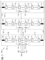
- FIG. 7 shows a three-phase modular multilevel converter 400 , again built from phase units 102 of FIG. 4 .
- the three-phase modular multilevel converter 400 uses three phase units 102 in parallel arrangement.
- the phase units 102 are connected to DC link lines 302 , 304 and the AC terminals 120 of the phase units form AC terminals 406 , 408 , 410 of the three-phase modular multilevel converter 400 .
- phase units 202 of FIG. 5 could be used in the three-phase modular multilevel converter 400 .
- the single phase modular multilevel converter 300 or the three-phase modular multilevel converter 400 may use an inductive element LI, L 2 on the outside, i.e. close to the DC terminals 104 , 105 as shown in FIGS. 4 to 7 .
- the inductive elements LI, L 2 could be arranged differently, such as close to the AC terminals 120 or as smaller inductive elements within the cells C or between the cells C.
- Some embodiments of the single phase modular multilevel converter 300 or the three-phase modular multilevel converter 400 may use the same type of cells C for all converter arms 108 , 110 , 112 , e.g. half-bridge cells CH or full-bridge cells CF. In some embodiments, different types of cells C may be used.
- the upper and lower converter arm 108 , 112 use full-bridge cells CH capable of DC fault blocking by controlling the phase-to-phase voltage between the cells C with the full-bridge cells CF to control current from the AC side to the DC side.
- the middle converter arm 110 that is not necessary for DC fault blocking uses only half-bridge cells CH for simpler control and fewer switches.
- FIGS. 8 to 10 show different embodiments of the bridging elements 118 , 124 , 218 , 224 incorporating teachings of the present disclosure.
- a single switch 802 e.g. an IGBT may be used as each of the bridging elements 118 , 124 , 218 , 224 as shown in FIG. 8 .
- the phase units 102 , 202 only use a single cell C in each of the converter arms 108 , 110 , 112 .
- a series 902 of switches such as IGBTs may be used as each of the bridging elements 118 , 124 , 218 , 224 as shown FIG. 9 .
- FIG. 10 shows a third possibility where a series 1002 of di odes is used for each of the bridging elements 118 , 124 , 218 , 224 .
- a single diode or a series 1002 of diodes can be used when the modular multilevel converter is used as a rectifier, i.e. in AC to DC operation.
Abstract
Description
-
- The controlling means may take the form of a microcontroller such as an FPGA. It may be adapted to control said upper and lower bridging elements.
- The voltage rating of each of the bridging elements may have a voltage rating equal to or higher than that of the middle converter arm.
- The capacitors of the cells in the middle converter arm may have a smaller capacity than the capacitors of the lower or upper converter arm. In a further embodiment the capacitors of the cells in the middle converter arm may have half the capacity of the capacitors of the lower or upper converter arm. A smaller capacity leads to a smaller size of the cells of the middle converter arm.
- The voltage rating of the middle, upper and lower converter arm may be equal.
- In some embodiments, the voltage rating of the middle converter arm may be lower than the voltage rating of the upper and/or lower converter arm.
- The bridging elements each comprise one or more switches that are optimized for low conduction losses. In a further embodiment the switches may be IGCTs (Integrated gate-commutated thyristors). This will advantageously reduce overall losses as the bridging elements have to switch only at a relatively low frequency of the order of the supply network frequency (50 Hz or 60 Hz). The bridging elements may switch at double the network frequency.
- The bridging elements may each comprise one or more diodes. Especially when the modular multilevel converter is used as a rectifier, using diodes makes the modular multilevel converter cheaper and simpler in setup and operation.
- The bridging elements may comprise one or more thyristors with reverse diodes as these have low conduction losses.
- One or more of the upper, lower, and middle converter arms may comprise a plurality of cells.
- In some embodiments, the cells of the upper and lower converter arm are full-bridge type cells while the cells of the middle converter arm are half-bridge type cells. This can allow DC fault blocking by controlling the phase-to-phase voltage between the cells with the full-bridges to control current from the AC side to the DC side.
- The modular multilevel converter may comprise three or more of said phase units arranged in parallel. This allows 3-phase operation of the modular multilevel converter.
- The modular multilevel converter may comprise a second upper bridging element arranged between said upper node and an AC terminal and a second lower bridging current control arranged between said lower node and said AC terminal. These second bridging elements allow bypassing the bridging elements and therefore enhance the reliability of the modular multilevel converter. In addition, the parallel second bridging elements reduce conduction losses by half.
- The modular multilevel converter may further comprise a first bridge switch between the middle point of the upper and lower bridging element and the AC terminal and a second bridge switch between the middle point of the second upper and lower bridging element and the AC terminal. These bridge switches allow disconnecting the bridging element and the second bridging element, respectively. Thus, a short circuit in either upper or lower bridging element can be controlled by disconnecting that particular bridging element. This enhances the reliability of the modular multilevel converter. Achieving the same reliability without the bridge switches would require additional switches in series, creating higher losses.
-
- In some embodiments, the other of the upper and lower bridging elements is turned off.
- In some embodiments, said networks may be loads or supply networks or any other sort of electrical network.
- In some embodiments, the control unit switches the bridging elements with a frequency that is twice the AC voltage frequency.
- The control unit may control the switching arrangements of the cells of the middle converter arm such that the individual switches are turned on and/or off when their voltage is zero thus reducing switching losses.
Claims (14)
Applications Claiming Priority (4)
| Application Number | Priority Date | Filing Date | Title |
|---|---|---|---|
| EP18154369.5A EP3522357A1 (en) | 2018-01-31 | 2018-01-31 | Modular multilevel converter |
| EP18154369 | 2018-01-31 | ||
| EP18154369.5 | 2018-01-31 | ||
| PCT/EP2018/097093 WO2019149438A1 (en) | 2018-01-31 | 2018-12-28 | Modular multilevel converter |
Publications (2)
| Publication Number | Publication Date |
|---|---|
| US20210083596A1 US20210083596A1 (en) | 2021-03-18 |
| US11233463B2 true US11233463B2 (en) | 2022-01-25 |
Family
ID=61132115
Family Applications (1)
| Application Number | Title | Priority Date | Filing Date |
|---|---|---|---|
| US16/965,296 Active US11233463B2 (en) | 2018-01-31 | 2018-12-28 | Modular multilevel converter |
Country Status (5)
| Country | Link |
|---|---|
| US (1) | US11233463B2 (en) |
| EP (2) | EP3522357A1 (en) |
| CN (1) | CN111656670B (en) |
| ES (1) | ES2899876T3 (en) |
| WO (1) | WO2019149438A1 (en) |
Families Citing this family (3)
| Publication number | Priority date | Publication date | Assignee | Title |
|---|---|---|---|---|
| EP3790181A1 (en) * | 2019-09-09 | 2021-03-10 | Siemens Aktiengesellschaft | Modular multilevel converter |
| WO2022017617A1 (en) * | 2020-07-24 | 2022-01-27 | Siemens Aktiengesellschaft | Converter and method for operating same |
| CN114826000A (en) * | 2022-05-09 | 2022-07-29 | 北京易菲盛景科技有限责任公司 | Three-bridge-arm multilevel converter |
Citations (5)
| Publication number | Priority date | Publication date | Assignee | Title |
|---|---|---|---|---|
| US8867244B2 (en) * | 2010-07-30 | 2014-10-21 | Alstom Technology Ltd. | HVDC converter including fullbridge cells for handling a DC side short circuit |
| US20170005590A1 (en) * | 2014-02-03 | 2017-01-05 | Kabushiki Kaisha Toshiba | Power converter |
| GB2541410A (en) | 2015-08-18 | 2017-02-22 | Alstom Technology Ltd | Voltage source converter and control thereof |
| US20180183231A1 (en) * | 2015-07-01 | 2018-06-28 | Nr Electric Co., Ltd | Fault current-suppressing damper topology circuit and control method thereof and converter |
| US20180212533A1 (en) * | 2014-07-22 | 2018-07-26 | Abb Schweiz Ag | A multilevel converter with reduced ac fault handling rating |
Family Cites Families (8)
| Publication number | Priority date | Publication date | Assignee | Title |
|---|---|---|---|---|
| CN102377324B (en) * | 2011-10-18 | 2013-09-04 | 吕遥 | Converter bridge arm suitable for high-voltage applications and application system thereof |
| CN102891611B (en) * | 2012-06-30 | 2014-10-08 | 华为技术有限公司 | Five-level power converter, and control method and control device for five-level power converter |
| US9559611B2 (en) * | 2012-09-28 | 2017-01-31 | General Electric Company | Multilevel power converter system and method |
| CN103633871B (en) * | 2013-11-20 | 2016-10-05 | 华南理工大学 | Mixed type multilevel converter based on full-bridge and half-bridge module and control method thereof |
| CN203590069U (en) * | 2013-11-20 | 2014-05-07 | 华南理工大学 | Mixed type multi-level converter based on full-bridge module and half-bridge module |
| FR3019699B1 (en) * | 2014-04-03 | 2016-05-13 | Schneider Toshiba Inverter Europe Sas | MULTI-LEVEL POWER CONVERTER |
| EP2961057A1 (en) * | 2014-06-26 | 2015-12-30 | Alstom Technology Ltd. | Voltage source converter and control thereof |
| US9667167B2 (en) * | 2014-07-15 | 2017-05-30 | General Electric Company | Systems and methods for power conversion with direct current fault ride-through capability |
-
2018
- 2018-01-31 EP EP18154369.5A patent/EP3522357A1/en not_active Ceased
- 2018-12-28 CN CN201880087985.2A patent/CN111656670B/en active Active
- 2018-12-28 ES ES18833901T patent/ES2899876T3/en active Active
- 2018-12-28 EP EP18833901.4A patent/EP3695502B1/en active Active
- 2018-12-28 WO PCT/EP2018/097093 patent/WO2019149438A1/en unknown
- 2018-12-28 US US16/965,296 patent/US11233463B2/en active Active
Patent Citations (6)
| Publication number | Priority date | Publication date | Assignee | Title |
|---|---|---|---|---|
| US8867244B2 (en) * | 2010-07-30 | 2014-10-21 | Alstom Technology Ltd. | HVDC converter including fullbridge cells for handling a DC side short circuit |
| US20170005590A1 (en) * | 2014-02-03 | 2017-01-05 | Kabushiki Kaisha Toshiba | Power converter |
| US20180212533A1 (en) * | 2014-07-22 | 2018-07-26 | Abb Schweiz Ag | A multilevel converter with reduced ac fault handling rating |
| US20180183231A1 (en) * | 2015-07-01 | 2018-06-28 | Nr Electric Co., Ltd | Fault current-suppressing damper topology circuit and control method thereof and converter |
| GB2541410A (en) | 2015-08-18 | 2017-02-22 | Alstom Technology Ltd | Voltage source converter and control thereof |
| US20180241321A1 (en) | 2015-08-18 | 2018-08-23 | General Electric Technology Gmbh | Voltage source converter and control thereof |
Non-Patent Citations (6)
| Title |
|---|
| Du Sixing et al: "An Active Cross-Connected Modular Multilevel Converter (AC-MMC) for a Medium-Voltage Motor Drive", IEEE Transactions on Industrial Electronics, IEEE Service Center, Piscataway, NJ, USA, vol. 63, No. 8, pp. 4707-4717, XP011616265, ISSN: 0278-0046, DOI: 10.1109/TIE.2016.2547875 [gefunden am Jul. 8, 2016] Figure 1-2. |
| DU SIXING; WU BIN; TIAN KAI; ZARGARI NAVID R.; CHENG ZHONGYUAN: "An Active Cross-Connected Modular Multilevel Converter (AC-MMC) for a Medium-Voltage Motor Drive", IEEE TRANSACTIONS ON INDUSTRIAL ELECTRONICS, IEEE SERVICE CENTER, PISCATAWAY, NJ., USA, vol. 63, no. 8, 1 August 2016 (2016-08-01), USA , pages 4707 - 4717, XP011616265, ISSN: 0278-0046, DOI: 10.1109/TIE.2016.2547875 |
| KUI WANG ; YONGDONG LI ; ZEDONG ZHENG: "A new transformerless cascaded multilevel converter topology", ENERGY CONVERSION CONGRESS AND EXPOSITION, 2009. ECCE. IEEE, IEEE, PISCATAWAY, NJ, USA, 20 September 2009 (2009-09-20), Piscataway, NJ, USA , pages 3124 - 3129, XP031887949, ISBN: 978-1-4244-2893-9, DOI: 10.1109/ECCE.2009.5316470 |
| Search Report for EP Application No. 18154369.2, 10 pages, dated Jul. 18, 2019. |
| Search Report for International Application No. PCT/EP2018/097093, 14 pages, dated Mar. 18, 2019. |
| Wang Kui et al: "A new transformerless cascaded multilevel converter topology", Energy Conversion Congress and Exposition, 2009. ECCE. IEEE, IEEE, Piscataway, NJ, USA, pp. 3124-3129, XP031887949, DOI: 10.1109/ECCE.2009.5316470; ISBN: 978-1-4244-2893-9 * pp. 3124-3125; figures 2,6. |
Also Published As
| Publication number | Publication date |
|---|---|
| ES2899876T3 (en) | 2022-03-15 |
| EP3695502B1 (en) | 2021-09-01 |
| CN111656670B (en) | 2023-10-27 |
| CN111656670A (en) | 2020-09-11 |
| WO2019149438A1 (en) | 2019-08-08 |
| EP3695502A1 (en) | 2020-08-19 |
| EP3522357A1 (en) | 2019-08-07 |
| US20210083596A1 (en) | 2021-03-18 |
Similar Documents
| Publication | Publication Date | Title |
|---|---|---|
| US11108338B2 (en) | Dual submodule for a modular multilevel converter and modular multilevel converter including the same | |
| US9748848B2 (en) | Modular multilevel DC/DC converter for HVDC applications | |
| AU2008218769B2 (en) | 3-phase high power ups | |
| US10637371B2 (en) | Interface arrangement between an alternating current power system and a direct current power system with control of converter valve for fault protection | |
| KR101791289B1 (en) | Multi-level inverter | |
| Liang et al. | Current source modular multilevel converter for HVDC and FACTS | |
| US8314602B2 (en) | Converter cell module, voltage source converter system comprising such a module and a method for controlling such a system | |
| MX2011002969A (en) | Power converter. | |
| US11075587B2 (en) | Modular multilevel converter and sub-module thereof | |
| EP2961057A1 (en) | Voltage source converter and control thereof | |
| US11233463B2 (en) | Modular multilevel converter | |
| EP2781014A1 (en) | Ac/dc multicell power converter for dual terminal hvdc connection | |
| WO2017182091A1 (en) | Converter arrangement | |
| US20200119559A1 (en) | Mmc converter and sub-modules thereof | |
| CN113474986B (en) | Converter unit for MMC, MMC and control method thereof | |
| Vozikis et al. | An improved alternate arm converter for HVDC applications | |
| EP3790181A1 (en) | Modular multilevel converter | |
| RU2446550C1 (en) | Voltage converter | |
| EP3806303A1 (en) | Alternating capacitor step-down dc/dc converter | |
| CN212435577U (en) | Power converter apparatus with fault current turn-off capability | |
| US10958190B2 (en) | Multi-level voltage sourced converter | |
| WO2020173550A1 (en) | Statcom with integrated energy storage | |
| CN116806410A (en) | Bidirectional DC/AC power conversion system with multiple DC links |
Legal Events
| Date | Code | Title | Description |
|---|---|---|---|
| AS | Assignment |
Owner name: SIEMENS AKTIENGESELLSCHAFT, GERMANY Free format text: ASSIGNMENT OF ASSIGNORS INTEREST;ASSIGNOR:ROBINSON, JONATHAN;REEL/FRAME:053323/0009 Effective date: 20200507 |
|
| FEPP | Fee payment procedure |
Free format text: ENTITY STATUS SET TO UNDISCOUNTED (ORIGINAL EVENT CODE: BIG.); ENTITY STATUS OF PATENT OWNER: LARGE ENTITY |
|
| STPP | Information on status: patent application and granting procedure in general |
Free format text: DOCKETED NEW CASE - READY FOR EXAMINATION |
|
| AS | Assignment |
Owner name: SIEMENS ENERGY GLOBAL GMBH & CO. KG, GERMANY Free format text: ASSIGNMENT OF ASSIGNORS INTEREST;ASSIGNOR:SIEMENS AKTIENGESELLSCHAFT;REEL/FRAME:057279/0865 Effective date: 20210407 |
|
| STPP | Information on status: patent application and granting procedure in general |
Free format text: NON FINAL ACTION MAILED |
|
| STPP | Information on status: patent application and granting procedure in general |
Free format text: RESPONSE TO NON-FINAL OFFICE ACTION ENTERED AND FORWARDED TO EXAMINER |
|
| STPP | Information on status: patent application and granting procedure in general |
Free format text: NOTICE OF ALLOWANCE MAILED -- APPLICATION RECEIVED IN OFFICE OF PUBLICATIONS |
|
| STPP | Information on status: patent application and granting procedure in general |
Free format text: PUBLICATIONS -- ISSUE FEE PAYMENT VERIFIED |
|
| STCF | Information on status: patent grant |
Free format text: PATENTED CASE |