US11233443B2 - Coil bending machine - Google Patents
Coil bending machine Download PDFInfo
- Publication number
- US11233443B2 US11233443B2 US16/226,968 US201816226968A US11233443B2 US 11233443 B2 US11233443 B2 US 11233443B2 US 201816226968 A US201816226968 A US 201816226968A US 11233443 B2 US11233443 B2 US 11233443B2
- Authority
- US
- United States
- Prior art keywords
- coil
- slot
- stator core
- segment
- face
- Prior art date
- Legal status (The legal status is an assumption and is not a legal conclusion. Google has not performed a legal analysis and makes no representation as to the accuracy of the status listed.)
- Active, expires
Links
Images


Classifications
-
- H—ELECTRICITY
- H02—GENERATION; CONVERSION OR DISTRIBUTION OF ELECTRIC POWER
- H02K—DYNAMO-ELECTRIC MACHINES
- H02K3/00—Details of windings
- H02K3/32—Windings characterised by the shape, form or construction of the insulation
- H02K3/34—Windings characterised by the shape, form or construction of the insulation between conductors or between conductor and core, e.g. slot insulation
- H02K3/345—Windings characterised by the shape, form or construction of the insulation between conductors or between conductor and core, e.g. slot insulation between conductor and core, e.g. slot insulation
-
- H—ELECTRICITY
- H02—GENERATION; CONVERSION OR DISTRIBUTION OF ELECTRIC POWER
- H02K—DYNAMO-ELECTRIC MACHINES
- H02K15/00—Methods or apparatus specially adapted for manufacturing, assembling, maintaining or repairing of dynamo-electric machines
- H02K15/04—Methods or apparatus specially adapted for manufacturing, assembling, maintaining or repairing of dynamo-electric machines of windings, prior to mounting into machines
- H02K15/0414—Windings consisting of separate elements, e.g. bars, hairpins, segments, half coils
- H02K15/0421—Windings consisting of separate elements, e.g. bars, hairpins, segments, half coils consisting of single conductors, e.g. hairpins
- H02K15/0428—Windings consisting of separate elements, e.g. bars, hairpins, segments, half coils consisting of single conductors, e.g. hairpins characterised by the method or apparatus for simultaneously twisting a plurality of hairpins
-
- H—ELECTRICITY
- H02—GENERATION; CONVERSION OR DISTRIBUTION OF ELECTRIC POWER
- H02K—DYNAMO-ELECTRIC MACHINES
- H02K15/00—Methods or apparatus specially adapted for manufacturing, assembling, maintaining or repairing of dynamo-electric machines
-
- H—ELECTRICITY
- H02—GENERATION; CONVERSION OR DISTRIBUTION OF ELECTRIC POWER
- H02K—DYNAMO-ELECTRIC MACHINES
- H02K15/00—Methods or apparatus specially adapted for manufacturing, assembling, maintaining or repairing of dynamo-electric machines
- H02K15/0025—Shaping or compacting conductors or winding heads after the installation of the winding in the core or machine ; Applying fastening means on winding heads
- H02K15/0031—Shaping or compacting conductors in slots or around salient poles
-
- H—ELECTRICITY
- H02—GENERATION; CONVERSION OR DISTRIBUTION OF ELECTRIC POWER
- H02K—DYNAMO-ELECTRIC MACHINES
- H02K15/00—Methods or apparatus specially adapted for manufacturing, assembling, maintaining or repairing of dynamo-electric machines
- H02K15/0056—Manufacturing winding connections
- H02K15/0068—Connecting winding sections; Forming leads; Connecting leads to terminals
- H02K15/0081—Connecting winding sections; Forming leads; Connecting leads to terminals for form-wound windings
- H02K15/0087—Connecting winding sections; Forming leads; Connecting leads to terminals for form-wound windings characterised by the method or apparatus for simultaneously twisting a plurality of hairpins open ends after insertion into the machine
-
- H—ELECTRICITY
- H02—GENERATION; CONVERSION OR DISTRIBUTION OF ELECTRIC POWER
- H02K—DYNAMO-ELECTRIC MACHINES
- H02K15/00—Methods or apparatus specially adapted for manufacturing, assembling, maintaining or repairing of dynamo-electric machines
- H02K15/02—Methods or apparatus specially adapted for manufacturing, assembling, maintaining or repairing of dynamo-electric machines of stator or rotor bodies
- H02K15/024—Methods or apparatus specially adapted for manufacturing, assembling, maintaining or repairing of dynamo-electric machines of stator or rotor bodies with slots
-
- H—ELECTRICITY
- H02—GENERATION; CONVERSION OR DISTRIBUTION OF ELECTRIC POWER
- H02K—DYNAMO-ELECTRIC MACHINES
- H02K15/00—Methods or apparatus specially adapted for manufacturing, assembling, maintaining or repairing of dynamo-electric machines
- H02K15/06—Embedding prefabricated windings in machines
- H02K15/062—Windings in slots; salient pole windings
- H02K15/064—Windings consisting of separate segments, e.g. hairpin windings
-
- H—ELECTRICITY
- H02—GENERATION; CONVERSION OR DISTRIBUTION OF ELECTRIC POWER
- H02K—DYNAMO-ELECTRIC MACHINES
- H02K15/00—Methods or apparatus specially adapted for manufacturing, assembling, maintaining or repairing of dynamo-electric machines
- H02K15/08—Forming windings by laying conductors into or around core parts
- H02K15/085—Forming windings by laying conductors into or around core parts by laying conductors into slotted stators
-
- H—ELECTRICITY
- H02—GENERATION; CONVERSION OR DISTRIBUTION OF ELECTRIC POWER
- H02K—DYNAMO-ELECTRIC MACHINES
- H02K15/00—Methods or apparatus specially adapted for manufacturing, assembling, maintaining or repairing of dynamo-electric machines
- H02K15/10—Applying solid insulation to windings, stators or rotors
Definitions
- the present disclosure generally relates to a coil bending machine, and more particularly to a coil bending machine that push-bends the lead portions of multiple U-shaped segment coils inserted into slots of a stator core.
- JP 2008-79443 A describes a conventional coil twisting machine.
- the coil twisting machine is configured to, while two lead portions of a segment coil which is a U-shaped lead wire are inserted into slots of a stator core, bend the end portions of the lead portions protruding from an end face of the stator core in a twisting manner. In doing so, a coil presser member is brought into contact with a bent portion of the U-shaped segment coil to restrict axial movement of the segment coil relative to the stator core.
- the coil presser member is brought into contact with the bent portion of the U-shaped segment coil to restrict axial movement of the segment coil.
- the bent portion of the segment coil may deform under the axial pressing load applied on the lead portion.
- springing back of the bent portion of the segment coil may cause fluctuation in the amounts of protrusion of the bent portions from the end face of the stator core.
- a coil bending machine is configured to, in a stator core including a cylindrical yoke and multiple teeth that protrude radially inward from the yoke and that are spaced uniformly in a circumferential direction, and having a slot formed between circumferentially adjacent teeth, while lead portions of a segment coil which is a U-shaped lead wire including a bent portion and two of the lead portions extending from the bent portion are inserted into two slots, push-bend end portions of the lead portions protruding from an axial end face of the stator core toward the stator core.
- the coil bending machine includes: a coil bending member that push-bends the end portions of the lead portions protruding from the axial end face of the stator core toward the stator core; and a coil pressing mechanism that press-fixes the segment coils inside the slot toward the yoke in the slot, from a radially inner side of the stator core.
- the coil pressing mechanism press-fixes the segment coils inside the slot toward the yoke in the slot, from the radially inner side of the stator core.
- the coil pressing mechanism preferably includes: a coil presser member that press-fixes the segment coils inside the slot toward the radially outer side; a cylindrical holding member that holds the coil presser member in a radially movable manner; an axially moving member that is provided on an inner side of the holding member in an axially movable manner, and has a tapered outer circumferential face in contact with an inner circumferential tilted face of the holding member; and driving means that moves the axially moving member in the axial direction.
- the driving means moves the axially moving member, and the tapered outer circumferential face of the axially moving member pushes the inner circumferential tilted face to move the coil presser member to the radially outer side, so that the segment coils in the slot may be press-fixed to the radially outer side.
- the driving means moves the axially moving member, and the tapered outer circumferential face of the axially moving member pushes the inner circumferential tilted face to move the coil presser member to the radially outer side, so that the segment coils in the slot may be press-fixed to the radially outer side.
- an axially extending slit preferably penetrates the coil presser member in the circumferential direction.
- the slit allows the coil presser member to elastically deform more easily in the radial direction.
- the segment coils in the slot may be press-fixed with a more stable pressing force than when the coil presser member is formed of a stiff body.
- an insulating sheet may be provided along a slot inner wall face inside the slot, both ends of the insulating sheet on the radially inner side may be arranged to open toward a radial opening of the slot, and a guide protrusion to be inserted between the both ends of the insulating sheet may be formed on an axial end face of a radially outer end portion of the coil presser member.
- the segment coil in the slot may be press-fixed with a stable pressing force.
- deformation of a bent portion of a segment coil may be suppressed to equalize the amounts of protrusion of the bent portions from an end face of a stator core.
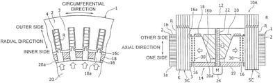
- FIG. 1 is a sectional view taken along the axial direction of a coil bending machine of an embodiment
- FIG. 2 is a fragmentary sectional view taken along the radial direction of the coil bending machine of the embodiment
- FIG. 3A is a radial view of how lead portions of a segment coil are press-fixed inside slots
- FIG. 3B is a circumferential view of how the lead portions of the segment coil are press-fixed inside the slot
- FIG. 4 is a view showing a coil bending machine of a comparative example in which a segment coil is not fixed inside a slot;
- FIG. 5 is a graph showing how the protrusion amount of a bent portion changes when the segment coil is not fixed inside the slot and the end portion of the lead portion is pushed down;
- FIG. 6 is a graph showing how the thickness of an insulating coating in the bent portion changes by indentation when the segment coil is not fixed inside the slot and the end portion of the lead portion is pushed down;
- FIG. 7 is a view showing a configuration in which a coil presser member is pressed by fixing bolts
- FIG. 8A is a graph showing the result of the coil movement amount when the bolt fastening torque is set to 1.2 N ⁇ m in the configuration shown in FIG. 7 ;
- FIG. 8B is a graph showing the result of the coil movement amount when the bolt fastening torque is set to 1.5 N ⁇ m in the configuration shown in FIG. 7 ;
- FIG. 9 is a graph showing a result of confirming that the segment coil can be fixable with a bolt fastening force of 1.5 N ⁇ m or larger;
- FIG. 10 is a graph showing that a bolt fastening force of 1.5 N ⁇ m or larger is equivalent to a coil pressing force of 500 N or larger;
- FIG. 11 is a graph showing how the thickness of the insulating coating in the bent portion changes by indentation when the segment coil is fixed with a coil pressing force of 500 N in the configuration shown in FIG. 7 ;
- FIG. 12 is a view showing an example in which two slits are formed in a coil presser member
- FIG. 13 is a view showing an example in which 11 slits are formed in a coil presser member
- FIG. 14 is a graph showing the relationship between the number of slits formed in a coil presser member and the fluctuation absorption amount
- FIG. 15A is a view showing a normal state where an insulating sheet is not sandwiched between the segment coil in a slot and the coil presser member;
- FIG. 15B is a view showing a state where the insulating sheet is sandwiched between the segment coil in the slot and the coil presser member;
- FIG. 16 is a graph showing that a coil fixing force deteriorates in adjacent slots when the insulating sheet is sandwiched
- FIG. 17 is a view showing an example in which a guide protrusion is provided in a tip end lower portion of a coil presser member
- FIG. 18 is a diagram showing an advantage of the guide protrusion shown in FIG. 17 ;
- FIG. 19A is a view showing how the tip end of a lead portion of a segment coil is positioned by being brought into contact with a bending member.
- FIG. 19B is a view showing how the tip end of a bent portion of a segment coil is positioned by being brought into contact with a fixing jig.
- FIG. 1 is a sectional view taken along the axial direction of a coil bending machine 10 of an embodiment
- FIG. 2 is a fragmentary sectional view taken along the radial direction of the coil bending machine 10 of the embodiment.
- the axial direction (or lamination thickness direction) of a stator core 1 is indicated by an arrow
- the radial direction and circumferential direction of the stator core 1 are indicated by arrows.
- the coil bending machine 10 is a machine for push-bending a lead portion R of a segment coil SC assembled onto the stator core 1 .
- the stator core 1 and the segment coil SC will first be described, and then the coil bending machine 10 will be described.
- the stator core 1 is composed of a cylindrical magnetic member.
- the stator core 1 is formed by axially laminating and integrally connecting flat rolled magnetic steel sheets punched into annular shapes, for example.
- the stator core 1 has a circumferentially extending yoke 2 , and multiple teeth 3 protruding radially inward from the yoke 2 .
- the teeth 3 are spaced uniformly in the circumferential direction in the yoke 2 . Additionally, the teeth 3 extend over the entire axial length of the stator core 1 .
- a slot 4 is formed between circumferentially adjacent teeth 3 .
- the slot 4 is an axially extending groove that opens on an axial end face of the stator core 1 , and also opens toward the radially inner side of the stator core 1 .
- a radially outer bottom portion of the slot 4 is formed by the yoke 2 , and is also referred to as a back yoke.
- a projecting portion projecting to both circumferential sides is formed on a radially inner end of each of the teeth 3 . Accordingly, the circumferential width of a radially inner opening portion of the slot 4 is narrower than the circumferential width of other parts of the slot 4 . This keeps the lead portion R of the segment coil SC placed inside the slot 4 from coming off to the radially inner side. Note that the circumferential width of the slot 4 is formed as a constant circumferential width except for the radially inner opening portion.
- FIG. 2 shows an example in which six lead portions R are arranged in the radial direction. Note, however, that the number of segment coils SC placed inside the slot 4 is not limited to six, and other number of segment coils SC (such as eight) may be provided.
- FIGS. 3A and 3B are views showing how the lead portion of the segment coil is press-fixed inside the slot.
- the segment coil SC is a U-shaped lead wire that includes, as one body, a bent portion K bent into a substantial V shape, and two lead portions R extending from both ends of the bent portion K.
- the two lead portions R of the segment coil SC extend in parallel to each other.
- the segment coil SC is formed of a square lead wire (e.g., flat wire) having a rectangular section, for example.
- the segment coil SC includes a copper wire as a conductive portion, and an insulating coating that covers the periphery of the copper wire. Note that although not shown, at the tip end of the lead portion R, the insulating coating is removed in advance for welding in a later step so that the copper wire is exposed.
- the insulating sheet 5 is made of a sheet material made of insulating resin, for example, and has a function of improving the insulating property between the lead portion R of the segment coil SC inside the slot 4 and the stator core 1 .
- the insulating sheet 5 is folded in advance to form a substantial U shape in axial view. In this state, the insulating sheet 5 is inserted from the axial direction to be placed inside the slot 4 . Accordingly, in the slot 4 , the insulating sheet 5 is placed along two inner wall faces facing each other in the circumferential direction, and a radial inner wall face positioned on the radially outer side. Meanwhile, on the radially inner side of the slot 4 , two end portions of the insulating sheet 5 are open, and a space between the two end portions faces the radially inner opening portion of the slot 4 .
- the two lead portions R of the segment coil SC are placed by being inserted into two slots 4 from an end face 1 a on one side in the axial direction of the stator core 1 . In doing so, the lead portion R is placed on the inner side of the insulating sheet 5 inside the slot 4 . In the embodiment, the two lead portions R are inserted not into circumferentially adjacent slots 4 , but into two slots 4 spaced apart in the circumferential direction with a predetermined number of slots 4 interposed therebetween. Multiple (e.g., six) segment coils SC are inserted in the same manner, and the lead portions R are arranged in the radial direction in all of the slots 4 . As shown in FIG. 1 , in each segment coil SC arranged in this manner, an end portion of the lead portion R protrudes from an end face 1 b on the other side in the axial direction of the stator core 1 .
- the stator core 1 in which the segment coils SC are arranged in the above-mentioned manner is set in the coil bending machine 10 .
- the stator core 1 is fixed by a fixing member 11 (see FIG. 3B ) or the like.
- the coil bending machine 10 includes a coil bending member 12 and a coil pressing mechanism 14 .
- the coil bending member 12 has a function of bending the end portion of the lead portion R of the segment coil SC protruding from the axial end face of the stator core 1 so as to push it down toward the stator core 1 .
- the tip end of each lead portion R engages with an engaging portion formed on a lower face of the coil bending member 12 .
- the coil bending member 12 rotates in the circumferential direction, while moving toward the stator core 1 . This bends and pushes down the end of the lead portion R toward the stator core 1 .
- the coil pressing mechanism 14 has a function of press-fixing the lead portion R of the segment coil SC inside the slot 4 toward the yoke 2 inside the slot 4 , from the radially inner side of the stator core 1 .
- the coil pressing mechanism 14 includes a coil presser member 16 , a holding member 18 , an axially moving member 20 , a threaded shaft 22 , and a motor 24 .
- the threaded shaft 22 and the motor 24 form driving means that moves the axially moving member 20 in the axial direction.
- the coil presser member 16 is a member that press-fixes the lead portion R of the segment coil SC inside the slot 4 toward the radially outer side.
- the coil presser members 16 are provided in the same number (e.g., 48) as the slots 4 .
- the coil presser member 16 is made of a metal plate, for example.
- the coil presser member 16 is formed into a substantial trapezoid in side view, and has a radially outer side face 16 a and a radially inner tilted face (inner circumferential tilted face) 16 b .
- the side face 16 a is formed along the axial direction.
- the tilted face 16 b is tilted with respect to the axial direction, and specifically, is tilted so as to spread radially outward gradually from one side to the other side in the axial direction.
- a radially outer end portion 16 c of the coil presser member 16 is formed narrower than other parts thereof. Hence, the end portion 16 c of the coil presser member 16 may be inserted into the slot 4 from the radially inner opening portion of the slot 4 .
- the holding member 18 is a member that holds the coil presser member 16 in a radially movable manner.
- the holding member 18 is composed of a cylindrical metal member, for example.
- the holding member 18 is fixed by being screwed, for example, to a disc-shaped base plate 19 .
- An axially long and narrow guide groove 18 a is formed in the holding member 18 in a position facing each slot 4 .
- the coil presser member 16 is radially slidably placed in the guide groove 18 a.
- the axially moving member 20 is provided on the inner side of the holding member 18 in an axially movable manner. As shown in FIG. 1 , the axially moving member 20 has a substantially truncated cone-shaped section, and has a tapered outer circumferential face 20 a tilted with respect to the axial direction. The tilt angle of the outer circumferential face 20 a is set to the same tilt angle as the tilted face 16 b of the coil presser member 16 . Accordingly, the entire outer circumferential face 20 a of the axially moving member 20 is brought into contact with the tilted face 16 b of the coil presser member 16 .
- a tapped hole axially penetrates the center of the axially moving member 20 , and the threaded shaft 22 is screwed into the tapped hole.
- the threaded shaft 22 is connected to a rotating shaft of the motor 24 fixed to the base plate 19 .
- the axially moving member 20 moves in a direction indicated by an arrow in FIG. 1 (downward in FIG. 1 ).
- This movement pushes and moves the coil presser member 16 having the tilted face 16 b in contact with the outer circumferential face 20 a of the axially moving member 20 toward the radially outer side.
- the end portion 16 c of the coil presser member 16 pushes the lead portion R inside the slot 4 toward the yoke 2 , whereby the segment coil SC is fixed to the stator core 1 .
- the embodiment describes a case where the driving means is composed of the threaded shaft 22 and the motor 24 , the invention is not limited to this.
- the motor 24 a bolt head formed integrally with the threaded shaft 22 may be used, and the threaded shaft 22 may be rotated by rotating the bolt head with a tool or the like.
- FIG. 4 is a view showing a coil bending machine of a comparative example in which a segment coil is not fixed inside a slot.
- a segment coil SC having lead portions R inserted and placed inside slots 4 is positioned with respect to a stator core 1 , by bringing the lower end of a bent portion K into contact with a positioning member 6 .
- an axial pressing load is applied by a coil bending member 7 to bend end portions of the lead portions R toward the stator core 1 .
- the bent portion K of the segment coil SC may undergo plastic deformation as indicated by a broken line in FIG. 4 , under the axial pressing load applied on the lead portions R.
- FIG. 5 is a graph showing how the protrusion amount of the bent portion K changes when the segment coil SC is not fixed inside the slot 4 and an end portion of a lead portion is pushed down.
- the horizontal axis of the graph indicates slot numbers, and the vertical axis indicates the amount of protrusion of the bent portion K from the end face 1 a of the stator core 1 .
- a lower scale indicates a larger protrusion amount.
- FIG. 6 is a graph showing how the thickness of the insulating coating in the bent portion K changes by indentation when the segment coil SC is not fixed inside the slot 4 and the end portion of the lead portion R is pushed down.
- the bent portions K whose gaps are designed in units of 0.1 mm, for example, are reported to contact each other and generate indentation on the insulating coating of the segment coils SC.
- the thickness of the insulating coating which is not less than a reference value before pushing down and bending, is reported to drop below the reference value. Accordingly, when the bending causes the bent portions of the segment coils SC to contact each other and generate indentation on the insulating coating, the insulating property between adjacent segment coils SC deteriorates.
- the coil pressing mechanism 14 press-fixes the lead portion R of the segment coil SC inside the slot 4 toward the yoke 2 in the slot 4 , from the radially inner side of the stator core 1 .
- the lead portion R does not move in the axial direction inside the slot 4 , even when an axial pressing load is applied to bend the lead portion R of the segment coil SC. Accordingly, it is possible to prevent transmission of axial load to the bent portion K of the segment coil SC, so that deformation of the bent portion K of the segment coil SC can be suppressed.
- the amounts of protrusion of the bent portions K of the segment coils from the end face 1 a of the stator core 1 can be equalized after bending of the coils.
- the bent portion K since the bent portion K does not move at the time of bending of the end portion of the lead portion R, a predetermined gap can be maintained between adjacent bent portions K, and generation of indentation on the insulating coating can be prevented. As a result, the insulating property between adjacent segment coils SC can be maintained.
- the inventors of the present application confirmed the coil fixing force by creating a coil pressing mechanism 14 A having a simple configuration as shown in FIG. 7 .
- a coil presser member 16 A is pushed against a segment coil SC inside a slot 4 by fastening two fixing bolts 28 screwed into a cylindrical member 26 .
- eight lead portions R of segment coils SC are arranged inside the slot 4 .
- the coil bending member applies an axial pressing force of 40 kN on the segment coil SC.
- FIG. 8A is a graph showing the result of the coil movement amount when the bolt fastening torque is set to 1.2 N ⁇ m in the configuration shown in FIG. 7
- FIG. 8B is a graph showing the result of the coil movement amount when the bolt fastening torque is set to 1.5 N ⁇ m in the configuration shown in FIG. 7
- NG failure
- the same axial pressing load is applied to the segment coils SC by setting the fastening torque of the fixing bolt to 1.5 N ⁇ m.
- the lead portions R of the segment coils SC inside the slot 4 do not move in the axial direction and are press-fixed.
- the fastening torque of the fixing bolt in the coil pressing mechanism 14 A in this case is preferably 1.5 N ⁇ m or larger.
- FIG. 9 is a graph showing a result of confirming that the segment coil can be fixable with a bolt fastening force of 1.5 N ⁇ m or larger.
- FIG. 10 is a graph showing that a bolt fastening force of 1.5 N ⁇ m or larger is equivalent to a coil pressing force of 500 N or larger.
- FIG. 11 is a graph showing how the thickness of the insulating coating in the bent portion changes by indentation when the segment coil is fixed with a coil pressing force of 500 N in the configuration shown in FIG. 7 .
- the horizontal axis indicates the fastening torque of the fixing bolt 28
- the vertical axis indicates the coil movement occurrence rate (%).
- the coil movement occurrence rate is calculated by dividing the number of slots exceeding a coil movement amount of 0.2 mm by the total number of slots.
- the horizontal axis indicates the fixing bolt fastening torque (N ⁇ m), and the vertical axis indicates the coil pressing force (N).
- N the fixing bolt fastening torque
- the vertical axis indicates the coil pressing force (N).
- This graph shows that a bolt fastening force of the fixing bolt 28 of 1.5 N ⁇ m or larger is equivalent to a coil pressing force of the coil presser member 16 A of 500 N or larger. Accordingly, it is confirmed that in the coil pressing mechanism 14 A of the configuration in FIG. 7 , the coils can be fixed securely inside the slot if the coil pressing force of the coil presser member 16 A is set to 500 N or larger.
- the horizontal axis indicates whether the coil is fixed inside the slot
- the vertical axis indicates the thickness of the insulating coating in the bent portion K in the segment coil SC.
- FIGS. 12 to 14 a coil bending machine 10 A as another embodiment will be described with reference to FIGS. 12 to 14 .
- the same elements as those of the coil bending machine 10 of the above embodiment are assigned the same reference numerals and overlapping descriptions will be omitted.
- FIG. 12 is a view showing an example in which two slits 30 are formed in a coil presser member 16 .
- the axially extending slits 30 penetrate the coil presser member 16 in the circumferential direction.
- the radially inner slit 30 extends from the vicinity of an end on one side of the coil presser member 16 in the axial direction to an end on the other side
- the axially outer slit 30 extends from the vicinity of the end on the other side of the coil presser member 16 in the axial direction to the end on the one side.
- Such slits 30 may be formed, for example, by forming a through hole penetrating the coil presser member made of a metal plate in the plate thickness direction by laser beam machining, and using the through hole as a start end to cut by wire-saw machining.
- the slits 30 allow the coil presser member 16 to elastically deform more easily in the radial direction. Hence, even when there is fluctuation in the product shape of the segment coils SC, the lead portions R of the segment coils SC can be press-fixed inside the slot 4 with a more stable pressing force than when the coil presser member 16 is formed of a stiff body (i.e., when there is no slit).
- FIG. 13 is a view showing an example in which 11 slits 30 are formed in a coil presser member 16 .
- FIG. 14 is a graph showing the relationship between the number of the slits 30 formed in the coil presser member 16 and the fluctuation absorption amount.
- 11 slits 30 are formed in the coil presser member 16 . More specifically, of the slits 30 , six slits 30 are aligned in the axial direction in the vicinity of the axially outer end, and five slits 30 are aligned in the axial direction on the radially inner side thereof. Note that the position and number of slits 30 are appropriately changeable depending on the desired fluctuation absorption amount and manufacturing cost, for example.
- the horizontal axis indicates the number of slits
- the vertical axis indicates the fluctuation absorption amount (mm).
- “fluctuation” refers to fluctuation in the overall radial length when multiple lead portions R of segment coils SC are radially laminated inside the slot 4 . Such fluctuation causes fluctuation in the coil pressing force of the coil presser member 16 among the slots, and leads to unstable coil pressing force.
- FIGS. 15 to 18 a coil bending machine 10 B as yet another embodiment will be described with reference to FIGS. 15 to 18 .
- the same elements as those of the coil bending machine 10 of the aforementioned embodiment are assigned the same reference numerals and overlapping descriptions will be omitted.
- a normal state where an insulating sheet 5 is not sandwiched between a lead portion R and the coil presser member 16 is preferably set as shown in FIG. 15A .
- This state is shown in the graph of FIG. 16 .
- the graph of FIG. 16 indicates that the coil pressing force drops below the reference value in the slot where the insulating sheet 5 is sandwiched and in the two adjacent slots, and coil movement occurs.
- a guide protrusion 17 to be inserted between both ends of the insulating sheet 5 is preferably formed on an axial end face of a radially outer end portion 16 c of the coil presser member 16 as in FIG. 17 . Since the guide protrusion 17 is formed into a substantially truncated cone shape and has a narrow and rounded tip end (lower end), it is easily inserted between the open ends of the insulating sheet 5 .
- the segment coil SC can be press-fixed with a stable pressing force equal to or larger than the target coil pressing force, in all of the slots 4 .
- FIG. 19A is a view showing how the tip end of a lead portion of a segment coil SC is positioned by being brought into contact with a coil bending member 12
- FIG. 19B is a view showing how the tip end of a bent portion of the segment coil SC is positioned by being brought into contact with a fixing jig 8 .
- a protrusion amount L 1 of the bent portion K from an end face 1 a on one side of the stator core 1 in the axial direction can be aligned
- a protrusion length L 2 of the lead portion R of the segment coil SC protruding from an end face 1 b on the other side of the stator core 1 in the axial direction includes manufacturing error of the segment coil SC itself and error in the lamination thickness of the stator core 1 in the axial direction.
- the protrusion length L 2 of the lead portion R from the end face 1 b on the other side of the stator core 1 in the axial direction does not include the production error of the segment coil SC and the error in the lamination thickness of the stator core 1 , and therefore the predefined dimension can be set accurately.
- the bending step by the coil bending machine 10 can be performed favorably.
- stator core 1 a , 1 b end face, 2 yoke, 3 teeth, 4 slot, 5 insulating sheet, 6 positioning member, 7 , 12 coil bending member, 8 fixing jig, 10 , 10 A, 10 B coil bending machine, 11 fixing member, 14 , 14 A coil pressing mechanism, 16 , 16 A coil presser member, 16 a side face, 16 b tilted face, 16 c end portion, 17 guide protrusion, 18 holding member, 18 a guide groove, 19 base plate, 20 axially moving member, 20 a outer circumferential face, 22 threaded shaft, 24 motor, 26 cylindrical member, 28 fixing bolt, 30 slit, SC segment coil, K bent portion, R lead portion.
Landscapes
- Engineering & Computer Science (AREA)
- Power Engineering (AREA)
- Manufacturing & Machinery (AREA)
- Manufacture Of Motors, Generators (AREA)
Abstract
Description
Claims (4)
Applications Claiming Priority (3)
| Application Number | Priority Date | Filing Date | Title |
|---|---|---|---|
| JP2017246015A JP6943753B2 (en) | 2017-12-22 | 2017-12-22 | Coil bending device |
| JP2017-246015 | 2017-12-22 | ||
| JPJP2017-246015 | 2017-12-22 |
Publications (2)
| Publication Number | Publication Date |
|---|---|
| US20190199183A1 US20190199183A1 (en) | 2019-06-27 |
| US11233443B2 true US11233443B2 (en) | 2022-01-25 |
Family
ID=66949616
Family Applications (1)
| Application Number | Title | Priority Date | Filing Date |
|---|---|---|---|
| US16/226,968 Active 2040-01-11 US11233443B2 (en) | 2017-12-22 | 2018-12-20 | Coil bending machine |
Country Status (3)
| Country | Link |
|---|---|
| US (1) | US11233443B2 (en) |
| JP (1) | JP6943753B2 (en) |
| CN (1) | CN109980870B (en) |
Families Citing this family (7)
| Publication number | Priority date | Publication date | Assignee | Title |
|---|---|---|---|---|
| JP6912534B2 (en) * | 2019-09-19 | 2021-08-04 | 富士精工株式会社 | Wire wire fixing jig for coil |
| JP7371506B2 (en) * | 2020-01-21 | 2023-10-31 | トヨタ紡織株式会社 | Armature manufacturing method and armature |
| CN111342624B (en) * | 2020-04-18 | 2024-05-28 | 山西汾西重工有限责任公司 | Engagement mechanism and engagement method for coil lead-out wire head after bending |
| JP7516862B2 (en) | 2020-05-25 | 2024-07-17 | トヨタ紡織株式会社 | Armature manufacturing method |
| WO2023145211A1 (en) | 2022-01-25 | 2023-08-03 | 日本発條株式会社 | Production method for armature |
| CN118575402A (en) * | 2022-01-25 | 2024-08-30 | 日本发条株式会社 | Armature manufacturing method |
| WO2023145209A1 (en) * | 2022-01-25 | 2023-08-03 | 日本発條株式会社 | Armature manufacturing method |
Citations (9)
| Publication number | Priority date | Publication date | Assignee | Title |
|---|---|---|---|---|
| JPS6062853A (en) | 1983-09-16 | 1985-04-11 | Hitachi Ltd | Coil forming machine |
| US5491886A (en) | 1993-08-12 | 1996-02-20 | Emerson Electric Co. | Gapless inner diameter stator winding blocking mechanism |
| JP2008079443A (en) | 2006-09-22 | 2008-04-03 | Denso Corp | Device for twisting conductor |
| JP2008148521A (en) | 2006-12-13 | 2008-06-26 | Denso Corp | Chuck device |
| JP2013172575A (en) | 2012-02-21 | 2013-09-02 | Toyota Motor Corp | Method of manufacturing stator and stator manufacturing apparatus |
| KR20140095667A (en) * | 2013-01-24 | 2014-08-04 | 엘지전자 주식회사 | Insulation member and motor having the same, manufacturing method for motor |
| JP2015104249A (en) | 2013-11-26 | 2015-06-04 | 株式会社豊田自動織機 | Coil joining method for rotary electric machine and coil for rotary electric machine |
| JP2016127692A (en) | 2014-12-26 | 2016-07-11 | アイシン・エィ・ダブリュ株式会社 | Stator assembly device and stator assembly method |
| WO2016140194A1 (en) * | 2015-03-02 | 2016-09-09 | 日特エンジニアリング株式会社 | Stator manufacturing device and manufacturing method |
Family Cites Families (3)
| Publication number | Priority date | Publication date | Assignee | Title |
|---|---|---|---|---|
| DE2903380A1 (en) * | 1979-01-30 | 1980-08-07 | Gottlob Thumm Gmbh & Co Kg | Stator winding pressing tool - has two halves for axial forming and segments for radial pressing |
| US20030135988A1 (en) * | 2001-10-12 | 2003-07-24 | Massimo Pelletta | Dynamo-electric machine component core coil forming system |
| CN201075793Y (en) * | 2007-07-26 | 2008-06-18 | 广东格兰仕集团有限公司 | Reshaping apparatus for motor stator coil |
-
2017
- 2017-12-22 JP JP2017246015A patent/JP6943753B2/en active Active
-
2018
- 2018-12-20 CN CN201811561952.5A patent/CN109980870B/en active Active
- 2018-12-20 US US16/226,968 patent/US11233443B2/en active Active
Patent Citations (10)
| Publication number | Priority date | Publication date | Assignee | Title |
|---|---|---|---|---|
| JPS6062853A (en) | 1983-09-16 | 1985-04-11 | Hitachi Ltd | Coil forming machine |
| US5491886A (en) | 1993-08-12 | 1996-02-20 | Emerson Electric Co. | Gapless inner diameter stator winding blocking mechanism |
| JP2008079443A (en) | 2006-09-22 | 2008-04-03 | Denso Corp | Device for twisting conductor |
| JP2008148521A (en) | 2006-12-13 | 2008-06-26 | Denso Corp | Chuck device |
| JP2013172575A (en) | 2012-02-21 | 2013-09-02 | Toyota Motor Corp | Method of manufacturing stator and stator manufacturing apparatus |
| KR20140095667A (en) * | 2013-01-24 | 2014-08-04 | 엘지전자 주식회사 | Insulation member and motor having the same, manufacturing method for motor |
| JP2015104249A (en) | 2013-11-26 | 2015-06-04 | 株式会社豊田自動織機 | Coil joining method for rotary electric machine and coil for rotary electric machine |
| JP2016127692A (en) | 2014-12-26 | 2016-07-11 | アイシン・エィ・ダブリュ株式会社 | Stator assembly device and stator assembly method |
| WO2016140194A1 (en) * | 2015-03-02 | 2016-09-09 | 日特エンジニアリング株式会社 | Stator manufacturing device and manufacturing method |
| US20170373570A1 (en) * | 2015-03-02 | 2017-12-28 | Nittoku Engineering Co., Ltd. | Stator manufacturing apparatus and stator manufacturing method |
Also Published As
| Publication number | Publication date |
|---|---|
| JP2019115139A (en) | 2019-07-11 |
| CN109980870A (en) | 2019-07-05 |
| US20190199183A1 (en) | 2019-06-27 |
| CN109980870B (en) | 2021-02-26 |
| JP6943753B2 (en) | 2021-10-06 |
Similar Documents
| Publication | Publication Date | Title |
|---|---|---|
| US11233443B2 (en) | Coil bending machine | |
| JP6390772B2 (en) | Stator assembly method and stator assembly apparatus | |
| US6933649B2 (en) | Method of installation of a laminated stator core stack in the motor casing | |
| EP3293860B1 (en) | Rotary electric rotor and method of manufacturing rotary electric rotor | |
| JP6121967B2 (en) | Rotor with balancer weight and motor | |
| US10536043B2 (en) | Modular unit comprising a laminate stack for an electric machine, method for producing such a modular unit, and electric machine | |
| US11469652B2 (en) | Method of manufacturing stacked core and apparatus for manufacturing stacked core | |
| WO2015087126A2 (en) | Rotary electric machine rotor | |
| CN111512527B (en) | Stator manufacturing method and stator | |
| US20110215666A1 (en) | Rotary electrical machine | |
| US7994680B2 (en) | Motor including electrical sheets having shear droops | |
| JP2015092801A (en) | Rotary electric machine, and method for manufacturing rotary electric machine stator | |
| JP2016127693A (en) | Stator assembly method and stator assembly device | |
| US20210099033A1 (en) | Stator for rotary electric machine, rotary electric machine, and producing method for stator for rotary electric machine | |
| US20130276296A1 (en) | Stator core manufacturing method | |
| US10361611B2 (en) | Coil end bending jig | |
| US11979058B2 (en) | Housing, rotating electrical machine using the same, and method of manufacturing housing of rotating electrical machine | |
| JP6693351B2 (en) | Stator manufacturing method | |
| JP2014023233A (en) | Stator of rotary electric machine | |
| US3996503A (en) | Variable capacitor | |
| WO2022003998A1 (en) | Wedge insertion device and coil insertion device | |
| US20210111596A1 (en) | Electrical machine with a spring element for holding a stator in a housing | |
| JP2019047679A (en) | Rotary electric machine and manufacturing method of the same | |
| JP2017051012A (en) | Coil pressing member | |
| JP2016032402A (en) | Stator of rotary electric machine |
Legal Events
| Date | Code | Title | Description |
|---|---|---|---|
| FEPP | Fee payment procedure |
Free format text: ENTITY STATUS SET TO UNDISCOUNTED (ORIGINAL EVENT CODE: BIG.); ENTITY STATUS OF PATENT OWNER: LARGE ENTITY |
|
| AS | Assignment |
Owner name: TOYOTA JIDOSHA KABUSHIKI KAISHA, JAPAN Free format text: ASSIGNMENT OF ASSIGNORS INTEREST;ASSIGNORS:MIZUSHIMA, DAISUKE;HIRAO, YASUYUKI;TAKEDA, HIROAKI;REEL/FRAME:048620/0455 Effective date: 20181218 Owner name: DENSO CORPORATION, JAPAN Free format text: ASSIGNMENT OF ASSIGNORS INTEREST;ASSIGNORS:MIZUSHIMA, DAISUKE;HIRAO, YASUYUKI;TAKEDA, HIROAKI;REEL/FRAME:048620/0455 Effective date: 20181218 |
|
| STPP | Information on status: patent application and granting procedure in general |
Free format text: NON FINAL ACTION MAILED |
|
| STPP | Information on status: patent application and granting procedure in general |
Free format text: RESPONSE TO NON-FINAL OFFICE ACTION ENTERED AND FORWARDED TO EXAMINER |
|
| STPP | Information on status: patent application and granting procedure in general |
Free format text: FINAL REJECTION MAILED |
|
| STPP | Information on status: patent application and granting procedure in general |
Free format text: RESPONSE AFTER FINAL ACTION FORWARDED TO EXAMINER |
|
| STPP | Information on status: patent application and granting procedure in general |
Free format text: NOTICE OF ALLOWANCE MAILED -- APPLICATION RECEIVED IN OFFICE OF PUBLICATIONS |
|
| STPP | Information on status: patent application and granting procedure in general |
Free format text: PUBLICATIONS -- ISSUE FEE PAYMENT VERIFIED |
|
| STCF | Information on status: patent grant |
Free format text: PATENTED CASE |