US11233442B2 - Rotary position sensor including switch and patterned magnet - Google Patents
Rotary position sensor including switch and patterned magnet Download PDFInfo
- Publication number
- US11233442B2 US11233442B2 US16/180,532 US201816180532A US11233442B2 US 11233442 B2 US11233442 B2 US 11233442B2 US 201816180532 A US201816180532 A US 201816180532A US 11233442 B2 US11233442 B2 US 11233442B2
- Authority
- US
- United States
- Prior art keywords
- ring magnet
- switch
- north
- south pole
- pole sections
- Prior art date
- Legal status (The legal status is an assumption and is not a legal conclusion. Google has not performed a legal analysis and makes no representation as to the accuracy of the status listed.)
- Active, expires
Links
Images


Classifications
-
- G—PHYSICS
- G01—MEASURING; TESTING
- G01D—MEASURING NOT SPECIALLY ADAPTED FOR A SPECIFIC VARIABLE; ARRANGEMENTS FOR MEASURING TWO OR MORE VARIABLES NOT COVERED IN A SINGLE OTHER SUBCLASS; TARIFF METERING APPARATUS; MEASURING OR TESTING NOT OTHERWISE PROVIDED FOR
- G01D5/00—Mechanical means for transferring the output of a sensing member; Means for converting the output of a sensing member to another variable where the form or nature of the sensing member does not constrain the means for converting; Transducers not specially adapted for a specific variable
- G01D5/12—Mechanical means for transferring the output of a sensing member; Means for converting the output of a sensing member to another variable where the form or nature of the sensing member does not constrain the means for converting; Transducers not specially adapted for a specific variable using electric or magnetic means
- G01D5/14—Mechanical means for transferring the output of a sensing member; Means for converting the output of a sensing member to another variable where the form or nature of the sensing member does not constrain the means for converting; Transducers not specially adapted for a specific variable using electric or magnetic means influencing the magnitude of a current or voltage
- G01D5/142—Mechanical means for transferring the output of a sensing member; Means for converting the output of a sensing member to another variable where the form or nature of the sensing member does not constrain the means for converting; Transducers not specially adapted for a specific variable using electric or magnetic means influencing the magnitude of a current or voltage using Hall-effect devices
- G01D5/145—Mechanical means for transferring the output of a sensing member; Means for converting the output of a sensing member to another variable where the form or nature of the sensing member does not constrain the means for converting; Transducers not specially adapted for a specific variable using electric or magnetic means influencing the magnitude of a current or voltage using Hall-effect devices influenced by the relative movement between the Hall device and magnetic fields
-
- H—ELECTRICITY
- H02—GENERATION; CONVERSION OR DISTRIBUTION OF ELECTRIC POWER
- H02K—DYNAMO-ELECTRIC MACHINES
- H02K11/00—Structural association of dynamo-electric machines with electric components or with devices for shielding, monitoring or protection
- H02K11/20—Structural association of dynamo-electric machines with electric components or with devices for shielding, monitoring or protection for measuring, monitoring, testing, protecting or switching
- H02K11/21—Devices for sensing speed or position, or actuated thereby
- H02K11/215—Magnetic effect devices, e.g. Hall-effect or magneto-resistive elements
-
- H—ELECTRICITY
- H02—GENERATION; CONVERSION OR DISTRIBUTION OF ELECTRIC POWER
- H02K—DYNAMO-ELECTRIC MACHINES
- H02K7/00—Arrangements for handling mechanical energy structurally associated with dynamo-electric machines, e.g. structural association with mechanical driving motors or auxiliary dynamo-electric machines
- H02K7/003—Couplings; Details of shafts
-
- H—ELECTRICITY
- H02—GENERATION; CONVERSION OR DISTRIBUTION OF ELECTRIC POWER
- H02K—DYNAMO-ELECTRIC MACHINES
- H02K7/00—Arrangements for handling mechanical energy structurally associated with dynamo-electric machines, e.g. structural association with mechanical driving motors or auxiliary dynamo-electric machines
- H02K7/10—Structural association with clutches, brakes, gears, pulleys or mechanical starters
- H02K7/116—Structural association with clutches, brakes, gears, pulleys or mechanical starters with gears
Definitions
- This invention relates generally to a rotary position sensor and, more specifically to an actuator with a rotary position sensor including a switch and a patterned magnet.
- Actuators are used in the automotive industry to actuate vehicle engine components including for example the vanes of a vehicle engine turbocharger.
- the position of the actuator is determined via the use of a rotary position sensor.
- Hall Effect sensor based sensors that sense and measure changes in the magnitude and/or direction of the magnetic field generated by a magnet have been used for sensing the position of the output shaft of an actuator.
- Position sensors have also been used that include a Hall Effect switch/latch and simple magnet on the rotatable output shaft.
- Back biased Hall Effect switches/latches have also been used in combination with an output shaft including voids or other features adapted to be sensed by the Hall Effect switch/latch.
- the present invention is directed to a new, simple, and inexpensive rotary position sensor adapted for use in for example a vehicle engine component actuator that uses a switch and a rotatable patterned ring magnet mounted to the output shaft of the actuator.
- the present invention is directed generally to a rotary position sensor comprising a rotatable ring magnet including at least a first pair of North and South Pole sections, each of the North and South Pole sections having a length, and a switch spaced from the ring magnet and adapted for sensing changes in the magnetic field generated by the ring magnet in response to the rotation of the ring magnet relative to the switch, the length of the respective North and South Pole sections of the ring magnet being predetermined to correspond to the one or more positions of the ring magnet adapted for sensing by the switch.
- the North and South Pole sections has a different length for sensing different positions of the ring magnet.
- the ring magnet is mounted to an output shaft of an actuator.
- the ring magnet is mounted to an end face of the output shaft and the ring magnet is magnetized in an axial direction relative to the output shaft.
- the switch is a Hall Effect switch.
- the rotatable ring magnet includes a plurality of pairs of North and South Pole sections extending around the circumference of the ring magnet in an alternating North and South Pole relationship and defining a plurality of North and South Pole switch points extending around the circumference of the ring magnet in a predetermined spaced relationship corresponding to a predetermined plurality of positions of the ring magnet adapted to be sensed by the switch.
- the present invention is also directed to a rotary position sensor adapted for sensing the position of a rotatable output shaft on an actuator, the rotary position sensor comprising a ring magnet mounted to the output shaft and rotatable in response to the rotation of the output shaft, the ring magnet being magnetized to include a plurality of North and South Pole sections, each of the North and South Pole sections having a length, and a switch spaced from the ring magnet and adapted for sensing changes in the magnetic field generated by the ring magnet in response to the rotation of the ring magnet and the output shaft relative to the switch, the length of the respective North and South Pole sections of the ring magnet corresponding to a plurality of positions of the ring magnet adapted for sensing by the switch.
- the North and South Pole sections have different lengths corresponding to different positions of the ring magnet adapted for sensing by the switch.
- the ring magnet is mounted to an end face of the ring magnet and is magnetized in a direction axial to the output shaft.
- the rotatable ring magnet includes a plurality of pairs of North and South Pole sections extending around the circumference of the ring magnet in an alternating North and South Pole relationship and defining a plurality of North and South Pole switch points extending around the circumference of the ring magnet in a predetermined spaced relationship corresponding to a predetermined plurality of positions of the ring magnet adapted to be sensed by the switch.
- the present invention is further directed to an actuator comprising a housing defining an interior cavity, an actuator motor located in the interior cavity, a plurality of gears located in the housing including a rotatable output gear assembly, and a rotary position sensor including a ring magnet mounted to the output gear assembly and rotatable in response to the rotation of the output gear assembly, the ring magnet being magnetized to include a plurality of North and South Pole sections, each of the North and South Pole sections having a length, and a switch spaced from the ring magnet and adapted for sensing changes in the magnetic field generated by the ring magnet in response to the rotation of the ring magnet and the output gear assembly relative to the switch, the length of the respective North and South Pole sections of the ring magnet corresponding to a plurality of positions of the ring magnet and the output gear assembly adapted for sensing by the switch.
- the ring magnet has been magnetized in a pattern including a plurality of diametrically opposed pairs of North and South Pole sections extending around the circumference of the ring magnet in an alternating and abutting relationship and defining a plurality of North and South Pole switch points extending around the circumference of the ring magnet and corresponding to the plurality of positions of the ring magnet and the output gear assembly adapted for sensing by the switch.
- the switch is a Hall Effect switch.
- the output gear assembly includes an output gear having an end face defining a ring shaped cavity adapted to receive the ring magnet.
- the end face of the output gear defines a plurality of grooves and the ring magnet includes a plurality of fingers fitted within the plurality of grooves for indexing the ring magnet on the output gear.
- FIG. 1 is a perspective view of an actuator incorporating a rotary position sensor in accordance with the present invention
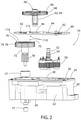
- FIG. 2 is an exploded perspective view of the actuator shown in FIG. 1 ;
- FIG. 3 is a vertical cross-sectional view of the actuator shown in FIG. 1 ;
- FIG. 4 is a perspective view of the actuator output gear assembly and depicting the direction of the magnetic field generated by the multiple magnetic North and South Pole pairs of the patterned ring magnet mounted on the output gear;
- FIG. 5 is a top plan view of the actuator output gear assembly and depicting the multiple magnetic North and South Pole pairs of the patterned ring magnet mounted on the output gear;
- FIG. 6 is a graph depicting the performance of the rotary position sensor of the present invention.
- FIGS. 1-5 depict a vehicle engine component actuator 10 incorporating a rotary position sensor assembly 110 in accordance with the present invention.
- the actuator 10 comprises a component housing 20 defined by a circumferentially extending exterior vertical wall 22 including a top circumferentially extending radial end face or lip or ledge 24 and defining a top housing opening 26 in communication with an interior hollow component cavity 30 .
- a printed circuit board or substrate 40 extends in a generally horizontal relationship generally normal to the vertical housing wall 22 , is seated on top of the radial end face 24 of the housing wall 22 , and covers the top housing opening 26 .
- the printed circuit board 40 includes a plurality of electrical components 42 mounted on top and bottom exterior surfaces or faces thereof including a Hall Effect latch/switch 112 which, in the embodiment shown, is seated on the top exterior surface or face of the printed circuit board 40 .
- the printed circuit board 40 also defines a pair of circular through-holes 44 and 46 extending through the body thereof and terminating in respective openings in the top and bottom exterior surfaces of the printed circuit board 40 .
- the actuator 10 comprises an electric actuator motor 50 that is located and seated in the interior housing cavity 30 .
- An elongate rotatable motor output shaft 52 extends outwardly from the motor 50 in a vertical direction and orientation generally spaced and parallel to the vertical housing wall 22 and normal to the printed circuit board 40 and includes a distal toothed end 54 extending through the through-hole 44 defined in the printed circuit board 40 .
- the actuator 10 also comprises a rotatable intermediate gear assembly 60 including a vertical elongate gear shaft 62 including a toothed lower end 64 and a horizontal planetary gear 66 at an upper end thereof with an exterior circumferentially extending toothed vertical side face 68 .
- the intermediate gear assembly 60 is located in the actuator 10 in a relationship with the toothed lower end 64 extending through the through-hole 46 defined in the printed circuit board 40 and into the housing interior cavity 30 and with the planetary gear 66 located and positioned exterior of the actuator 10 and the printed circuit board 40 in a relationship and orientation spaced from and parallel to the exterior upper surface of the printed circuit board 40 with the toothed vertical end face 68 of the gear 66 in toothed engaged relationship with the toothed distal end 54 of the motor output shaft 52 .
- the actuator 10 still further comprises a rotatable output gear assembly 70 located in the interior housing cavity 30 and including a vertical elongate gear shaft 72 and a horizontal planetary gear 74 at an upper end thereof including an exterior circumferentially extending toothed vertical side face 76 .
- a rotatable output gear assembly 70 located in the interior housing cavity 30 and including a vertical elongate gear shaft 72 and a horizontal planetary gear 74 at an upper end thereof including an exterior circumferentially extending toothed vertical side face 76 .
- the output gear assembly 70 is located and seated in the interior cavity 30 of the housing 20 in a relationship with the gear shaft 72 oriented in a relationship generally spaced and parallel to the vertical housing wall 22 and including a lower toothed end 78 coupled to a lower base wall 29 of the housing 20 and adapted for connection to a vehicle engine component adapted for actuation by the actuator 10 including, for example, the vanes of a vehicle engine turbocharger.
- the planetary gear 74 extends and is orientated in a relationship spaced and parallel to the lower exterior surface or face of the printed circuit board 40 .
- a pair of bearings 77 in the housing cavity 30 mount the output shaft 72 for rotation in and relative to the housing 20 .
- the planetary gear 74 includes a top exterior radial end surface or face 75 defining an interior ring shaped and circumferentially extending cavity or recess 77 extending into the end face 75 of the gear 74 and further defining a plurality of grooves 79 .
- a pair of opposed and spaced apart grooves 79 are defined in and extend into the opposed spaced apart gear walls defining the ring shaped cavity 77 in a co-linear relationship while another of the grooves 79 is spaced on the output gear 74 from the pair of grooves 79 and extends into the inner one of the gear walls defining the ring shaped cavity 77 .
- the activation of the actuator motor 50 results in the rotation of the motor output shaft 52 which in turn results in the rotation of the actuator intermediate gear assembly 60 coupled to the motor output shaft 52 via the intermediate gear 66 coupled to the motor output shaft 52 which in turn results in the rotation of the actuator output gear assembly 70 coupled to the intermediate gear assembly 60 via the output gear 74 that is coupled to the lower end 64 of the intermediate gear shaft 62 which in turn results in the rotation of the actuator output shaft 72 which in turn results in the rotation of the lower end 78 of the output gear shaft 62 that is coupled to the vehicle engine component which in turn results in the activation of the vehicle engine component (not shown) such as, for example, the activation/movement of the vanes of a vehicle engine turbocharger.
- the vehicle engine component not shown
- the actuator 10 further comprises a rotary position sensor 110 in accordance with the present invention and adapted for sensing the rotary position of the output gear shaft 72 and thus the position of the vehicle engine component (not shown) coupled to the output gear shaft 72 .
- the rotary position sensor 110 comprises a patterned ring magnet 114 mounted to and seated on the upper exterior horizontal end face 75 of the horizontal planetary gear 74 of the output gear assembly 70 in a relationship generally spaced and parallel to the lower exterior horizontal surface or face of the printed circuit board 40 .
- the patterned ring magnet 114 is rotatable in response to the rotation of the gear 74 of the output gear shaft assembly 70 .
- the patterned ring magnet 114 is seated in the interior of the ring shaped cavity 77 defined in the radial end face 75 of the output gear 74 .
- the ring magnet 114 also includes a plurality of tongues or fingers 115 extending normally outwardly from one or both of the exterior side surfaces or faces of the body of the ring magnet 114 .
- the ring magnet 114 includes a first pair of fingers 115 extending outwardly from opposed sides of the ring magnet 114 in a diametrically opposed and co-linear relationship.
- the ring magnet 114 also includes a third finger 115 that is spaced on the ring magnet 114 from the pair of fingers 115 and extends outwardly from the inner side surface of the ring magnet 114 .
- the patterned ring magnet 114 is seated and located in the ring shaped cavity 77 defined in the top exterior face of the output gear 74 in a relationship with the pair of tongues 115 on the ring magnet 114 extending respectively into the pair of grooves 79 defined in the top exterior face 75 of the output gear 74 and the third one of the tongues 115 on the ring magnet 1114 extending into the third one of the grooves 79 formed in the top exterior face 75 of the output gear 74 .
- the combination of the tongues 115 and grooves 79 are adapted to properly locate/index the ring magnet 114 on the output gear 74 , and the pair of cooperating tongues 115 and grooves 79 prevent the ring magnet 114 from being seated on the output gear 74 in an inverse/reverse relationship.
- the rotary position sensor 110 further comprises the Hall Effect switch or latch 112 that is mounted and seated on the top exterior surface of the printed circuit board 40 in a relationship and orientation overlying and generally vertically co-linearly aligned with the ring-shaped patterned ring magnet 114 .
- the printed circuit board 40 is located between and separates the Hall Effect switch/latch 112 from the patterned ring magnet 114 .
- the switch 112 may comprise any element suitable for sensing a change in the direction of the magnetic pole orientation of the patterned ring magnet 114 including for example a Hall Effect switch/latch, an MR (magnetic resonance switch), or a TMR (tunnel magnetoresistance) switch.
- the ring magnet 114 is magnetized to generate a magnetic field pattern including a plurality of/multiple curvilinear shaped and circumferentially extending adjoining and abutting pairs of North and South magnetic field pole sections or segments adapted to allow the sensing of a plurality of/multiple positions of the magnet 114 and thus adapted to allow the sensing of a plurality of/multiple unique and distinct positions of the actuator output shaft assembly 70 which in turn allows the position of the vehicle component to be determined such as for example the position of the vanes of a vehicle engine turbocharger.
- the ring magnet 114 has been magnetized in a manner and magnetic field pattern including a plurality of pairs of North and South magnetic field pole sections or segments extending along the circumference of the ring magnet 114 in an axial direction relative to the output gear 74 .
- the ring magnet 114 can be magnetized in a manner and magnetic field pattern including a plurality of pairs of North and South magnetic field pole segments or sections extending along the circumference of the ring magnet 114 in a radial direction relative to the output gear 74 .
- the ring magnet 114 has been magnetized in a manner and magnetic field pattern including a plurality of alternating North (N) and South (S) Pole sections or segments and more specifically, in the embodiment shown, a first pair of diametrically opposed and curvilinear shaped North Pole sections or segments 130 and 132 and a second pair of diametrically opposed and curvilinear shaped South Pole sections or segments 134 and 136 extending around the circumference of the ring magnet 114 in an adjoining, abutting, and alternating North and South Pole relationship.
- the ring magnet 114 is patterned in a relationship in which each of the North and South magnetic Pole sections or segments 130 , 132 , 134 , and 136 includes a different predetermined and preselected length corresponding to each of the unique and distinct predetermined and preselected output shaft positions adapted to be sensed.
- the plurality of magnet pole sections or segments 130 , 132 , 134 , and 136 of predetermined and preselected length define and from a plurality of/multiple predetermined and preselected magnet pole interface or switch points 140 , 142 , 144 , and 146 , i.e. a plurality of predetermined and preselected points or locations along the circumference of the ring magnet 114 wherein the magnetization orientation/direction of the magnetic field generated by the ring magnet 114 switches from North to South and vice versa, and corresponding to the plurality of unique predetermined and preselected output shaft positions adapted to be sensed and determined by the Hall Effect switch/latch 112 .
- the graph of FIG. 6 depicts the four switch points 140 , 142 , 144 , and 146 and thus the four unique output shaft positions adapted to be sensed.
- the number and length of the plurality of magnetic pole sections or segments 130 , 132 , 134 , and 136 formed and defined in the ring magnet 114 and thus the number and position/location of the plurality of magnet pole interface or switch points 140 , 142 , 144 , and 146 extending along the circumference of the ring magnet 114 may be varied depending on the number of unique and separate output shaft positions adapted to be sensed by the Hall Effect switch/latch 112 .
Landscapes
- Engineering & Computer Science (AREA)
- Power Engineering (AREA)
- Physics & Mathematics (AREA)
- General Physics & Mathematics (AREA)
- Microelectronics & Electronic Packaging (AREA)
- Transmission And Conversion Of Sensor Element Output (AREA)
Priority Applications (2)
| Application Number | Priority Date | Filing Date | Title |
|---|---|---|---|
| PCT/US2018/059215 WO2019094334A1 (en) | 2017-11-07 | 2018-11-05 | Rotary position sensor including switch and patterned magnet |
| US16/180,532 US11233442B2 (en) | 2017-11-07 | 2018-11-05 | Rotary position sensor including switch and patterned magnet |
Applications Claiming Priority (2)
| Application Number | Priority Date | Filing Date | Title |
|---|---|---|---|
| US201762582832P | 2017-11-07 | 2017-11-07 | |
| US16/180,532 US11233442B2 (en) | 2017-11-07 | 2018-11-05 | Rotary position sensor including switch and patterned magnet |
Publications (2)
| Publication Number | Publication Date |
|---|---|
| US20190140524A1 US20190140524A1 (en) | 2019-05-09 |
| US11233442B2 true US11233442B2 (en) | 2022-01-25 |
Family
ID=66329008
Family Applications (1)
| Application Number | Title | Priority Date | Filing Date |
|---|---|---|---|
| US16/180,532 Active 2039-08-26 US11233442B2 (en) | 2017-11-07 | 2018-11-05 | Rotary position sensor including switch and patterned magnet |
Country Status (4)
| Country | Link |
|---|---|
| US (1) | US11233442B2 (zh) |
| EP (1) | EP3707477B1 (zh) |
| CN (1) | CN111247396B (zh) |
| WO (1) | WO2019094334A1 (zh) |
Families Citing this family (2)
| Publication number | Priority date | Publication date | Assignee | Title |
|---|---|---|---|---|
| US11401013B2 (en) * | 2018-08-30 | 2022-08-02 | Jacob Marsden | Shift interrupt method for a marine propulsion system |
| FR3120434B3 (fr) | 2021-03-08 | 2023-10-13 | Moving Magnet Tech | Capteur à aimant et pôles ferromagnétiques |
Citations (25)
| Publication number | Priority date | Publication date | Assignee | Title |
|---|---|---|---|---|
| US5300848A (en) | 1989-11-14 | 1994-04-05 | Sunstrand Corporation | Dual permanent magnet generator planetary gear actuator and rotor phase shifting method |
| US5698910A (en) | 1995-12-22 | 1997-12-16 | Eastman Kodak Company | Electromagnetic actuator with position sensor |
| US5886517A (en) | 1995-03-02 | 1999-03-23 | Reichmann; Siegfried | Displacement pick-up for detecting of actuator with two indexing wheels |
| US6127752A (en) | 1997-03-12 | 2000-10-03 | Robert Bosch Gmbh | Motor with RPM pickup via a hall sensor |
| US6211794B1 (en) | 2000-04-06 | 2001-04-03 | Borgwarner | Analog rotary position sensor |
| US20010002599A1 (en) | 1999-01-29 | 2001-06-07 | Ab Elektronik Gmbh | Hall effect rotation sensor for a throttle valve unit |
| US20040119465A1 (en) | 2002-12-23 | 2004-06-24 | American Electronic Components, Inc. | Wheel-speed sensor |
| US6771065B2 (en) | 2001-02-26 | 2004-08-03 | Woodward Governor Company | Line hall effect detector and method of sensing angular position particularly suited for electrical rotary actuator |
| US20050035759A1 (en) | 2002-09-13 | 2005-02-17 | Michel Herbert | Device for determining the movement of a drive shaft |
| US7141904B2 (en) | 2002-05-22 | 2006-11-28 | Arvinmeritor Light Vehicle Systems-France | Gear reduction unit and geared motor connector |
| US20100072988A1 (en) * | 2008-09-22 | 2010-03-25 | Infineon Technologies Ag | System that obtains a switching point with the encoder in a static position |
| US7752943B2 (en) | 2006-11-01 | 2010-07-13 | Harmonic Drive Systems Inc. | Actuator provided with wave reduction gear |
| US20110273789A1 (en) | 2010-05-05 | 2011-11-10 | Digital Imaging Systems Gmbh | Linear motor with integral position sensor |
| US8324892B2 (en) * | 2005-07-26 | 2012-12-04 | Ebm-Papst St. Georgen Gmbh & Co. Kg | Absolute encoder and method for generating an absolute value for a angle of rotation |
| US8390277B2 (en) * | 2009-10-22 | 2013-03-05 | Kabushiki Kaisha Tokai Rika Denki Seisakusho | Rotational angle detector |
| US20150008907A1 (en) * | 2012-02-29 | 2015-01-08 | Zentrum Mikroelektronik Dresden Ag | Apparatus and method for the redundant, absolute position determination of a movable body |
| US8975793B2 (en) | 2012-07-18 | 2015-03-10 | Delphi Technologies, Inc. | Actuator assembly with rotational position sensor |
| US20150226581A1 (en) * | 2012-08-23 | 2015-08-13 | Melexis Technologies Nv | Arrangement, Method and Sensor for Measuring an Absolute Angular Position Using a Multi-Pole Magnet |
| US9322632B2 (en) | 2011-12-05 | 2016-04-26 | Gm Global Technology Operations Inc. | Linear position sensor assembly having magnetic shield |
| US20160123774A1 (en) | 2014-10-31 | 2016-05-05 | Allegro Microsystems, Llc | Magnetic Field Sensor for Sensing a Movement of a Ferromagnetic Target Object |
| US20170089940A1 (en) * | 2015-09-29 | 2017-03-30 | Honeywell International Inc. | Amr speed and direction sensor for use with magnetic targets |
| US20170237312A1 (en) | 2016-01-15 | 2017-08-17 | Cts Corporation | Actuator |
| US20170370961A1 (en) | 2016-06-27 | 2017-12-28 | Smc Corporation | Position detecting device |
| US20180087549A1 (en) | 2015-06-15 | 2018-03-29 | Festo Ag & Co. Kg | Rotary Drive Having a Position Detection Device and Calibration Method |
| FR3056841A1 (fr) * | 2016-09-28 | 2018-03-30 | Moving Magnet Tech | Motoreducteur presentant un capteur de position entourant la roue de sortie |
Family Cites Families (14)
| Publication number | Priority date | Publication date | Assignee | Title |
|---|---|---|---|---|
| US5633546A (en) * | 1993-12-30 | 1997-05-27 | Emerson Electric Co. | Magnetic sensor for switched reluctance motor |
| DE19817356A1 (de) * | 1998-04-18 | 1999-10-21 | Bosch Gmbh Robert | Winkelgeber und Verfahren zur Winkelbestimmung |
| DE10017542A1 (de) | 2000-04-08 | 2001-10-11 | Bosch Gmbh Robert | Vorrichtung zur Positions- und/oder Drehzahlerkennung eines rotierenden Teils |
| US20040217758A1 (en) * | 2003-05-02 | 2004-11-04 | Leonard John R. | Electromagnetic shaft position sensor and method |
| DE102006012890A1 (de) * | 2006-03-13 | 2007-09-20 | Valeo Schalter Und Sensoren Gmbh | Schalter, insbesondere Fahrzeugschalter, Auswerteeinheit hierfür und zugehörige Schaltereinheit |
| DE602007006974D1 (de) * | 2007-12-11 | 2010-07-15 | Alcatel Lucent | Positionssensor, Auswertschaltung und elektrischer Motor |
| WO2010096365A1 (en) * | 2009-02-17 | 2010-08-26 | Cts Corporation | Rotary position sensor |
| DE102009034744A1 (de) * | 2009-02-24 | 2010-09-30 | Mehnert, Walter, Dr. | Absoluter magnetischer Positionsgeber |
| CN102597706B (zh) * | 2009-11-13 | 2015-07-29 | Cts公司 | 通轴旋转位置传感器 |
| US8901921B2 (en) * | 2009-11-25 | 2014-12-02 | Infineon Technologies Ag | Angle measurement system for determining an angular position of a rotating shaft |
| WO2012014697A1 (ja) * | 2010-07-30 | 2012-02-02 | Thk株式会社 | エンコーダ、アクチュエータ |
| US8390276B2 (en) * | 2010-09-27 | 2013-03-05 | Bourns Incorporated | Target magnet assembly for a sensor used with a steering gear |
| KR101252218B1 (ko) * | 2011-12-12 | 2013-04-05 | 현대자동차주식회사 | 흡기밸브 개폐 조절용 액추에이터 제어장치 |
| US10024690B2 (en) * | 2015-04-14 | 2018-07-17 | Texas Instruments Incorporated | Incremental rotary encoder using hall effect sensors and magnetic detents |
-
2018
- 2018-11-05 WO PCT/US2018/059215 patent/WO2019094334A1/en unknown
- 2018-11-05 US US16/180,532 patent/US11233442B2/en active Active
- 2018-11-05 CN CN201880068548.6A patent/CN111247396B/zh active Active
- 2018-11-05 EP EP18807800.0A patent/EP3707477B1/en active Active
Patent Citations (25)
| Publication number | Priority date | Publication date | Assignee | Title |
|---|---|---|---|---|
| US5300848A (en) | 1989-11-14 | 1994-04-05 | Sunstrand Corporation | Dual permanent magnet generator planetary gear actuator and rotor phase shifting method |
| US5886517A (en) | 1995-03-02 | 1999-03-23 | Reichmann; Siegfried | Displacement pick-up for detecting of actuator with two indexing wheels |
| US5698910A (en) | 1995-12-22 | 1997-12-16 | Eastman Kodak Company | Electromagnetic actuator with position sensor |
| US6127752A (en) | 1997-03-12 | 2000-10-03 | Robert Bosch Gmbh | Motor with RPM pickup via a hall sensor |
| US20010002599A1 (en) | 1999-01-29 | 2001-06-07 | Ab Elektronik Gmbh | Hall effect rotation sensor for a throttle valve unit |
| US6211794B1 (en) | 2000-04-06 | 2001-04-03 | Borgwarner | Analog rotary position sensor |
| US6771065B2 (en) | 2001-02-26 | 2004-08-03 | Woodward Governor Company | Line hall effect detector and method of sensing angular position particularly suited for electrical rotary actuator |
| US7141904B2 (en) | 2002-05-22 | 2006-11-28 | Arvinmeritor Light Vehicle Systems-France | Gear reduction unit and geared motor connector |
| US20050035759A1 (en) | 2002-09-13 | 2005-02-17 | Michel Herbert | Device for determining the movement of a drive shaft |
| US20040119465A1 (en) | 2002-12-23 | 2004-06-24 | American Electronic Components, Inc. | Wheel-speed sensor |
| US8324892B2 (en) * | 2005-07-26 | 2012-12-04 | Ebm-Papst St. Georgen Gmbh & Co. Kg | Absolute encoder and method for generating an absolute value for a angle of rotation |
| US7752943B2 (en) | 2006-11-01 | 2010-07-13 | Harmonic Drive Systems Inc. | Actuator provided with wave reduction gear |
| US20100072988A1 (en) * | 2008-09-22 | 2010-03-25 | Infineon Technologies Ag | System that obtains a switching point with the encoder in a static position |
| US8390277B2 (en) * | 2009-10-22 | 2013-03-05 | Kabushiki Kaisha Tokai Rika Denki Seisakusho | Rotational angle detector |
| US20110273789A1 (en) | 2010-05-05 | 2011-11-10 | Digital Imaging Systems Gmbh | Linear motor with integral position sensor |
| US9322632B2 (en) | 2011-12-05 | 2016-04-26 | Gm Global Technology Operations Inc. | Linear position sensor assembly having magnetic shield |
| US20150008907A1 (en) * | 2012-02-29 | 2015-01-08 | Zentrum Mikroelektronik Dresden Ag | Apparatus and method for the redundant, absolute position determination of a movable body |
| US8975793B2 (en) | 2012-07-18 | 2015-03-10 | Delphi Technologies, Inc. | Actuator assembly with rotational position sensor |
| US20150226581A1 (en) * | 2012-08-23 | 2015-08-13 | Melexis Technologies Nv | Arrangement, Method and Sensor for Measuring an Absolute Angular Position Using a Multi-Pole Magnet |
| US20160123774A1 (en) | 2014-10-31 | 2016-05-05 | Allegro Microsystems, Llc | Magnetic Field Sensor for Sensing a Movement of a Ferromagnetic Target Object |
| US20180087549A1 (en) | 2015-06-15 | 2018-03-29 | Festo Ag & Co. Kg | Rotary Drive Having a Position Detection Device and Calibration Method |
| US20170089940A1 (en) * | 2015-09-29 | 2017-03-30 | Honeywell International Inc. | Amr speed and direction sensor for use with magnetic targets |
| US20170237312A1 (en) | 2016-01-15 | 2017-08-17 | Cts Corporation | Actuator |
| US20170370961A1 (en) | 2016-06-27 | 2017-12-28 | Smc Corporation | Position detecting device |
| FR3056841A1 (fr) * | 2016-09-28 | 2018-03-30 | Moving Magnet Tech | Motoreducteur presentant un capteur de position entourant la roue de sortie |
Non-Patent Citations (1)
| Title |
|---|
| W. D. Collins and R. Brown, "Synchronous running of shaded-pole permanent magnet motors," in IMA Journal of Applied Mathematics, vol. 73, No. 5, pp. 703-723, Oct. 2008. |
Also Published As
| Publication number | Publication date |
|---|---|
| US20190140524A1 (en) | 2019-05-09 |
| EP3707477A1 (en) | 2020-09-16 |
| CN111247396B (zh) | 2022-11-04 |
| WO2019094334A1 (en) | 2019-05-16 |
| CN111247396A (zh) | 2020-06-05 |
| EP3707477B1 (en) | 2023-07-05 |
Similar Documents
| Publication | Publication Date | Title |
|---|---|---|
| JP5401902B2 (ja) | モータ | |
| US7400141B2 (en) | Magnetic type angle sensor | |
| KR20200018472A (ko) | 회전각 센서 | |
| US11233442B2 (en) | Rotary position sensor including switch and patterned magnet | |
| US20020190709A1 (en) | Methods and apparatus for sensing angular position and speed of a rotatable shaft utilizing linearized annular magnet and commutated ratiometric hall sensors | |
| JP2008233090A (ja) | 指示要素及び磁気回転角センサ | |
| US6873151B2 (en) | Sensor assembly for sensing angular position | |
| US6614223B2 (en) | Analog angle encoder having a single piece magnet assembly surrounding an air gap | |
| US10371498B2 (en) | Linear inductive position sensor for an angle measurement of a mechanical component in rotation | |
| JP2006234573A (ja) | 回転角度検出装置 | |
| WO2007062766A1 (de) | Elektromotor | |
| US20190078910A1 (en) | Actuator with position sensor assembly | |
| JP6555289B2 (ja) | 回転センサ | |
| JP2007509336A (ja) | 高分解能の多回転測定システム及びこのシステムを有する軸受 | |
| CN109313006B (zh) | 用于高准确度磁位置感测的系统、方法和物体 | |
| RU2615612C2 (ru) | Бесконтактный истинно двухосевой датчик угла поворота вала | |
| WO2019099378A1 (en) | Rotary actuator with annular motor and gearset | |
| US7323864B2 (en) | Absolute angular position sensor on 360 of a rotating element | |
| US10539430B2 (en) | Position detecting device | |
| JP2002174532A (ja) | 無接触可変電圧器 | |
| JP4539968B2 (ja) | 回転角度センサ | |
| US20240159570A1 (en) | Magnet sensor and ferromagnetic poles | |
| KR20080109357A (ko) | 자동차 배기가스 순환밸브의 위치센싱을 위한 라운드형상의 자석부 | |
| KR20140122334A (ko) | 모터 | |
| KR20080109358A (ko) | 자동차 배기가스 순환밸브의 회전체 각도센싱을 위한자석부 |
Legal Events
| Date | Code | Title | Description |
|---|---|---|---|
| FEPP | Fee payment procedure |
Free format text: ENTITY STATUS SET TO UNDISCOUNTED (ORIGINAL EVENT CODE: BIG.); ENTITY STATUS OF PATENT OWNER: LARGE ENTITY |
|
| AS | Assignment |
Owner name: CTS CORPORATION, ILLINOIS Free format text: ASSIGNMENT OF ASSIGNORS INTEREST;ASSIGNOR:WOLSCHLAGER, KEVIN C.;REEL/FRAME:047446/0685 Effective date: 20181107 |
|
| STPP | Information on status: patent application and granting procedure in general |
Free format text: DOCKETED NEW CASE - READY FOR EXAMINATION |
|
| STPP | Information on status: patent application and granting procedure in general |
Free format text: RESPONSE TO NON-FINAL OFFICE ACTION ENTERED AND FORWARDED TO EXAMINER |
|
| STPP | Information on status: patent application and granting procedure in general |
Free format text: FINAL REJECTION MAILED |
|
| STPP | Information on status: patent application and granting procedure in general |
Free format text: RESPONSE AFTER FINAL ACTION FORWARDED TO EXAMINER |
|
| STPP | Information on status: patent application and granting procedure in general |
Free format text: ADVISORY ACTION MAILED |
|
| STPP | Information on status: patent application and granting procedure in general |
Free format text: NOTICE OF ALLOWANCE MAILED -- APPLICATION RECEIVED IN OFFICE OF PUBLICATIONS |
|
| STPP | Information on status: patent application and granting procedure in general |
Free format text: PUBLICATIONS -- ISSUE FEE PAYMENT VERIFIED |
|
| STCF | Information on status: patent grant |
Free format text: PATENTED CASE |