US11233434B2 - Rotor - Google Patents
Rotor Download PDFInfo
- Publication number
- US11233434B2 US11233434B2 US16/655,888 US201916655888A US11233434B2 US 11233434 B2 US11233434 B2 US 11233434B2 US 201916655888 A US201916655888 A US 201916655888A US 11233434 B2 US11233434 B2 US 11233434B2
- Authority
- US
- United States
- Prior art keywords
- flow passage
- refrigerant flow
- hole
- passage hole
- circumferential
- Prior art date
- Legal status (The legal status is an assumption and is not a legal conclusion. Google has not performed a legal analysis and makes no representation as to the accuracy of the status listed.)
- Active, expires
Links
Images


Classifications
-
- H—ELECTRICITY
- H02—GENERATION; CONVERSION OR DISTRIBUTION OF ELECTRIC POWER
- H02K—DYNAMO-ELECTRIC MACHINES
- H02K1/00—Details of the magnetic circuit
- H02K1/06—Details of the magnetic circuit characterised by the shape, form or construction
- H02K1/22—Rotating parts of the magnetic circuit
- H02K1/32—Rotating parts of the magnetic circuit with channels or ducts for flow of cooling medium
-
- H—ELECTRICITY
- H02—GENERATION; CONVERSION OR DISTRIBUTION OF ELECTRIC POWER
- H02K—DYNAMO-ELECTRIC MACHINES
- H02K1/00—Details of the magnetic circuit
- H02K1/06—Details of the magnetic circuit characterised by the shape, form or construction
- H02K1/22—Rotating parts of the magnetic circuit
- H02K1/27—Rotor cores with permanent magnets
- H02K1/2706—Inner rotors
- H02K1/272—Inner rotors the magnetisation axis of the magnets being perpendicular to the rotor axis
- H02K1/274—Inner rotors the magnetisation axis of the magnets being perpendicular to the rotor axis the rotor consisting of two or more circumferentially positioned magnets
- H02K1/2753—Inner rotors the magnetisation axis of the magnets being perpendicular to the rotor axis the rotor consisting of two or more circumferentially positioned magnets the rotor consisting of magnets or groups of magnets arranged with alternating polarity
- H02K1/276—Magnets embedded in the magnetic core, e.g. interior permanent magnets [IPM]
- H02K1/2766—Magnets embedded in the magnetic core, e.g. interior permanent magnets [IPM] having a flux concentration effect
-
- H—ELECTRICITY
- H02—GENERATION; CONVERSION OR DISTRIBUTION OF ELECTRIC POWER
- H02K—DYNAMO-ELECTRIC MACHINES
- H02K2213/00—Specific aspects, not otherwise provided for and not covered by codes H02K2201/00 - H02K2211/00
- H02K2213/03—Machines characterised by numerical values, ranges, mathematical expressions or similar information
Definitions
- the present invention relates to a rotor of an electric rotary machine.
- a rotor which includes a rotor shaft hole into which a rotor shaft is tightened, a refrigerant flow passage hole provided radially outside the rotor shaft hole and having a plurality of hole portions arranged in a circumferential direction, and an electromagnetic portion provided radially outside the refrigerant flow passage hole and having a plurality of magnet insertion holes into which magnets are respectively inserted has been disclosed.
- JP-A-2010-081657 describes that a refrigerant flowing through the refrigerant flow passage hole provided in the rotor core is supplied to a coil end using a centrifugal force generated by rotation of the rotor.
- JP-A-2010-081657 cools coils of a stator and does not cool the magnet disposed in the rotor. Therefore, the refrigerant flow passage hole described in JP-A-2010-081657 cannot be diverted as it is. In order to cool the magnet placed on the rotor, it is necessary to bring the refrigerant flow passage hole closer to the magnet.
- refrigerant supply holes are arranged in a vicinity of the magnetic pole portion, there is a possibility that the refrigerant supply holes may be deformed by a tightening load of the rotor shaft to the rotor shaft hole and an outer peripheral portion of the rotor core may be deformed.
- the invention provides a rotor having excellent cooling performance while suppressing deformation of an outer peripheral portion of a rotor core due to a tightening load of a rotor shaft.
- a rotor including: a rotor core having: a rotor shaft hole to which a rotor shaft is tightened; and a plurality of magnet insertion holes provided along a circumferential direction; and a plurality of magnetic pole portions constituted by magnets inserted into the magnet insertion holes, wherein: the rotor core includes a cooling portion having a plurality of refrigerant flow passage hole portions provided radially inward of the plurality of magnetic pole portions and arranged along the circumferential direction; a refrigerant flow passage hole portion of the plurality of refrigerant flow passage hole portions includes: a first refrigerant flow passage hole located on a virtual line connecting a circumferential center of each magnetic pole portion and a center of the rotor core; and a pair of second refrigerant flow passage holes facing each other across the first refrigerant flow passage hole on both circumferential end portion sides of each magnetic pole portion; the first refrigerant flow passage hole and the pair of
- both the first refrigerant flow passage hole and the second refrigerant flow passage hole include the inner radial side apex portions protruding radially inward, the inner radial side apex portion is deformed so as to be pushed radially outward with respect to the tightening load of the rotor shaft.
- the refrigerant flow passage hole since it is possible to absorb the tightening load of the rotor shaft and to suppress the deformation of the outer peripheral portion of the rotor core, it becomes possible to arrange the refrigerant flow passage hole further on the outer peripheral side of the rotor core, and thus the cooling performance of the rotor is improved.
- the refrigerant flow path can be formed further on the outer peripheral side of the rotor core, and thus the cooling performance of the rotor is improved.
- FIG. 1 is a front view of a rotor core according to a first embodiment of the invention
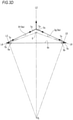
- FIG. 2 is a partially enlarged view of FIG. 1 ;
- FIG. 3A is an enlarged view of a hole portion of a first hole portion group
- FIG. 3B is a view illustrating a force acting when the outer radial side apex portion of the first hole portion group is located inside an intersection point X;
- FIG. 3C is a view illustrating a force acting when the outer radial side apex portion of the first hole portion group is located at the intersection point X;
- FIG. 3D is a view illustrating a force acting when the outer radial side apex portion of the first hole portion group is located outside the intersection point X;
- FIG. 4A is an enlarged view of a hole portion of a second hole portion group
- FIG. 4B is a view illustrating a force acting on the hole portion of the second hole portion group.
- FIG. 5 is an enlarged view of a hole portion of a third hole portion group.
- a rotor core 1 is configured by laminating a plurality of electromagnetic steel plates in an axial direction of a rotor shaft 2 and constitutes a rotor 100 of a motor together with the rotor shaft 2 and a plurality of magnets 3 assembled to the rotor core 1 .
- the rotor core 1 has an annular shape in which a rotor shaft hole 4 into which the rotor shaft 2 is tightened by press-fitting is provided at a center CL.
- the rotor core 1 includes a first hole portion group 6 having a plurality of hole portions 5 provided on the outer side of the rotor shaft hole 4 in a radial direction and arranged in a circumferential direction and a shaft holding portion 7 provided between the rotor shaft hole 4 and the first hole portion group 6 in the radial direction.
- the rotor core 1 includes a second hole potion group 9 having a plurality of hole portions 8 provided on the outer side of the first hole portion group 6 in the radial direction and arranged in the circumferential direction and a first annular portion 10 provided between the first hole portion group 6 and the second hole portion group 9 in the radial direction.
- the rotor core 1 includes a third hole potion group 12 having a plurality of hole portions 11 provided on the outer side of the second hole portion group 9 in the radial direction and arranged in the circumferential direction, a second annular portion 13 provided between the second hole portion group 9 and the third hole portion group 12 in the radial direction, a cooling portion 33 having a plurality of refrigerant flow passage hole portions 30 provided on the outer side of the third hole portion group 12 in the radial direction and arranged in the circumferential direction, and an electromagnetic portion 15 provided on the outer side of the refrigerant flow passage hole portion 30 in the radial direction and having a plurality of magnet insertion holes 14 into which the magnets 3 are respectively inserted.
- the electromagnetic portion 15 is disposed on an outer peripheral portion of the rotor core 1 and faces a stator (not illustrated).
- a plurality of magnetic pole portions 20 are formed at regular intervals along the circumferential direction.
- Each of the magnetic pole portions 20 is constituted of three magnets 3 inserted into three magnet insertion holes 14 arranged in a substantially arc shape which protrudes inward in the radial direction.
- the magnet 3 is, for example, a permanent magnet such as neodymium magnet. It is preferable that the magnetic pole portion 20 be configured such that a circumferential center portion is located radially inward of the rotor core 1 with respect to both circumferential end portions.
- the magnetic pole portion 20 may be constituted of two magnets arranged in two magnet insertion holes arranged in a substantially V-shape opening radially outward or it may be constituted by one arc magnet arranged in one magnet insertion hole formed in an arc shape convex radially inward.
- the cooling portion 33 is disposed radially inward of the electromagnetic portion 15 and has a plurality of refrigerant flow passage hole portions 30 disposed along the circumferential direction.
- the refrigerant flow passage hole portion 30 communicates with a refrigerant supply path (not illustrated) provided inside the rotor shaft 2 .
- the refrigerant flows axially from one side of the refrigerant flow passage hole portion 30 to the other side, thereby cooling the magnet 3 arranged in each magnetic pole portion 20 .
- the refrigerant may flow from the center of the refrigerant flow passage hole portion 30 in the axial direction to both sides to cool the magnet 3 disposed in each magnetic pole portion 20 .
- the refrigerant which cooled the magnet 3 disposed in each magnetic pole portion 20 may be discharged to the outside from an end surface of the rotor core 1 or may return to the rotor shaft 2 .
- the refrigerant flow passage hole portion 30 includes a first refrigerant flow passage hole 31 located on a virtual line L 1 connecting the center of each magnetic pole portion 20 and a center CL of the rotor core 1 and a pair of second refrigerant flow passage holes 32 located on imaginary lines L 2 passing through circumferential end portions of each magnetic pole portion 20 and the center CL of the rotor core 1 and facing each other across the first refrigerant flow passage hole 31 .
- the virtual line L 1 coincides with a d-axis, which is the center axis of the magnetic pole portion 20
- the virtual line L 2 coincides with a q-axis, which is 90 degrees apart from the d-axis by an electrical angle.
- the second refrigerant flow passage hole 32 located on a circumferential first end portion side is in common with the second refrigerant flow passage hole 32 located on a circumferential second end portion side of the magnetic pole portion 20 adjacent to the circumferential first end portion side.
- the second refrigerant flow passage hole 32 located on the circumferential second end portion side is in common with the second refrigerant flow passage hole 32 located on the circumferential first end portion side of the magnetic pole portion 20 adjacent to the circumferential second end portion side. That is, the first refrigerator flow passage holes 31 and the second refrigerator flow passage holes 32 are alternately arranged in the circumferential direction.
- the refrigerant flows to the second refrigerant flow passage hole 32 , and thus the circumferential first end portion side of the magnetic pole portion 20 and the circumferential second end portion side of the magnetic pole portion 20 adjacent to the circumferential first end portion side are cooled by one refrigerant flow passage, and similarly, the circumferential second end portion side of the magnetic pole portion 20 and the circumferential first end portion side of the magnetic pole portion 20 adjacent to the circumferential second end portion side are cooled by one refrigerant flow passage.
- the structure of rotor core 1 can be simplified.
- the first refrigerant flow passage hole 31 has a substantially pentagonal shape having an apex portion protruding radially inward.
- the first refrigerant flow passage hole 31 has an outer radial side first end portion 31 a and an outer radial side second end portion 31 b which form both circumferential end portions of the outer radial side, an inner radial side first end portion 31 c and an inner radial side second end portion 31 d which form both circumferential end portions of the inner radial side, and an inner radial side apex portion 31 e which is disposed on the virtual line L 1 , has a shorter radial distance from the center CL of the rotor core 1 than the inner radial side first end portion 31 c and the inner radial side second end portion 31 d , and forms a radial inner side apes portion.
- the first refrigerant flow passage hole 31 has an outer peripheral wall 31 f extending substantially linearly from the outer radial side first end portion 31 a to the outer radial side second end portion 31 b , an inner peripheral wall 31 g having a first inner peripheral wall 31 h extending substantially linearly from the inner radial side first end portion 31 c to the inner radial side apex portion 31 e and a second inner peripheral wall 31 i extending substantially linearly from the inner radial side second end portion 31 d to the inner radial side apex portion 31 e , a first side wall 31 j extending substantially linearly from the outer radial side first end portion 31 a to the inner radial side first end portion 31 c , and a second side wall 31 k extending substantially linearly from the outer radial side second end portion 31 b to the inner radial side second end portion 31 d.
- the outer peripheral wall 31 f of the first refrigerant flow passage hole 31 is substantially orthogonal to the virtual line L 1 .
- the inner peripheral wall 31 g of the first refrigerant flow passage hole 31 has a convex shape protruding radially inward. Furthermore, the inner peripheral wall 31 g of the first refrigerant flow passage hole 31 is substantially parallel to an outer peripheral wall 11 e of the hole portion 11 of the third hole portion group 12 adjacent to a rib 18 described below.
- first inner peripheral wall 31 h of the first refrigerant flow passage hole 31 is substantially parallel to a second outer peripheral wall 11 g of the hole portion 11 of the third hole portion group 12 adjacent to the circumferential first end portion side of the rib 18 described below and the second inner peripheral wall 31 of the first refrigerant flow passage hole 31 is substantially parallel to a first outer peripheral wall 11 f of the hole portion 11 of the third hole portion group 12 adjacent to the circumferential second end portion side of the rib 18 described below.
- a width W 31 f of the outer peripheral wall 31 f of the first refrigerant flow passage hole 31 is shorter than a width W 31 g of the inner peripheral wall 31 g.
- the first refrigerant flow passage hole 31 deforms such that the inner radial side apex portion 31 e is pushed radially outward with respect to a tightening load of the rotor shaft 2 . Due to the deformation of the first refrigerant flow passage hole 31 , the tightening load of the rotor shaft 2 is absorbed by the first refrigerant flow passage hole 31 .
- the outer peripheral wall 31 f of the first refrigerant flow passage hole 31 has a linear shape orthogonal to the virtual line L 1 , a force acting on the outer peripheral wall 31 f by the tightening load of the rotor shaft 2 has substantially no radial component at the circumferentially central portion of the outer peripheral wall 31 f . Thereby, it can suppress that the outer peripheral portion of the rotor core 1 deforms radially outward by the tightening load of the rotor shaft 2 .
- the first refrigeration flow passage hole 31 can be arranged further on the outer peripheral side of the rotor core 1 . As a result, it is possible to improve the cooling performance of the rotor 100 .
- the second refrigerant flow passage hole 32 has a substantially rectangular shape convex on both sides in the circumferential direction and both sides in the radial direction.
- the second refrigerant flow passage hole 32 has a first end portion 32 a and a second end portion 32 b forming both circumferential end portions, an outer radial side apex portion 32 c which is disposed on the virtual line L 2 , has a longer radial distance from the center CL of the rotor core 1 than the first end portion 32 a and the second end portion 32 b , and forms a radially outer apex portion, and an inner radial side apex portion 32 d which is disposed on the virtual line L 2 , has a shorter radial distance from the center CL of the rotor core 1 than the first end portion 32 a and the second end portion 32 b , and forms a radially inner apex portion.
- the second refrigerant flow passage hole 32 includes an inner peripheral wall 32 h which has a first inner peripheral wall 32 i extending substantially linearly from the first end portion 32 a to the inner radial side apex portion 32 d and a second inner peripheral wall 32 j extending substantially linearly from the second end portion 32 b to the inner radial side apex portion 32 d.
- the outer radial side apex portion 32 c of the second refrigerant flow passage hole 32 is located radially outward of the innermost radial portion of the magnetic pole portion 20 .
- the second outer peripheral wall 32 g is substantially parallel to a radially inner end surface 3 a of the magnet 3 disposed on the circumferential first end portion side of the magnetic pole portion 20 and the first outer peripheral wall 32 f is substantially parallel to a radially inner end surface 3 a of the magnet 3 disposed on the circumferential second end portion side of the magnetic pole portion 20 adjacent to the circumferential first end portion side.
- the first outer peripheral wall 32 f is substantially parallel to a radially inner end surface 3 a of the magnet 3 disposed on the circumferential second end portion side of the magnetic pole portion 20 and the second outer peripheral wall 32 g is substantially parallel to a radially inner end surface 3 a of the magnet 3 disposed on the circumferential first end portion side of the magnetic pole portion 20 adjacent to the circumferential second end portion side.
- the second refrigerant flow passage hole 32 can be formed in the vicinity of the circumferential end portion of the magnetic pole portion 20 while securing the q-axis magnetic path, so that the cooling performance of the rotor 100 is improved without the q-axis inductance decreasing.
- the second inner peripheral wall 32 j is substantially parallel to the first side wall 31 j of the first refrigerant flow passage hole 31 and the first inner peripheral wall 32 i is substantially parallel to the second side wall 31 k of the first refrigerant flow passage hole 31 of the magnetic pole portion 20 adjacent to the circumferential first end portion side.
- the first inner peripheral wall 32 i is substantially parallel to the second side wall 31 k of the first refrigerant flow passage hole 31 and the second inner peripheral wall 32 j is substantially parallel to the first side wall 31 j of the first refrigerant flow passage hole 31 of the magnetic pole portion 20 adjacent to the circumferential first end portion side.
- the first hole portion group 6 , the second hole portion group 9 , and the third hole portion group 12 , which are disposed radially inward of the cooling portion 33 , and the first annular portion 10 and the second annular portion 13 , which are formed by those hole portion groups 6 , 9 , and 12 , will be described.
- the first hole portion group 6 , the second hole portion group 9 , and the third hole portion group 12 and the first annular portion 10 and the second annular portion 13 which are formed by those hole portion groups 6 , 9 , and 12 , function as regions for absorbing the centrifugal force due to the rotation of the rotor and the tightening load of the rotor shaft 2 .
- a rib 16 is formed between adjacent hole portions 5 of the first hole portion group 6 .
- the rib 16 is disposed so that the circumferential center position is located on the virtual line L 1 .
- Each hole portion 8 of the second hole portion group 9 is arranged to intersect with the virtual line L 1 . That is, the hole portions 5 of the first hole portion group 6 and the hole portions 8 of the second hole portion group 9 are alternately arranged in the circumferential direction. Thereby, the centrifugal force can be absorbed by the hole portion 8 of the second hole portion group 9 and the transfer of the centrifugal force to the rib 16 can be suppressed.
- Each hole portion 8 of the second hole portion group 9 of the embodiment is arranged so that the circumferential center position is located on the virtual line L 1 . Furthermore, each hole portion 8 of the second hole portion group 9 has a circumferential length longer than that of the rib 16 and circumferentially overlaps both adjacent hole portions 5 with the rib 16 interposed therebetween.
- a rib 17 is formed between adjacent hole portions 8 of the second hole portion group 9 .
- the rib 17 is disposed so that the circumferential center position is located on the virtual line L 2 .
- Each hole portion 11 of the third hole portion group 12 is arranged to intersect with the virtual line L 2 . That is, the hole portions 8 of the second hole portion group 9 and the hole portions 11 of the third hole portion group 12 are alternately arranged in the circumferential direction. Thereby, the centrifugal force can be absorbed by the hole portion 11 of the third hole portion group 12 and the transfer of the centrifugal force to the rib 17 can be suppressed.
- Each hole portion 11 of the third hole portion group 12 of the embodiment is arranged so that the circumferential center position is located on the virtual line L 2 . Furthermore, each hole portion 11 of the third hole portion group 12 has a circumferential length longer than that of the rib 17 and circumferentially overlaps both adjacent hole portions 8 with the rib 17 interposed therebetween.
- a plurality of hole portions 5 of the first hole portion group 6 , a plurality of hole portions 8 of the second hole portion group 9 , and a plurality of hole portions 11 of the third hole portion group 12 are arranged at equal intervals in the circumferential direction. Thereby, each of the hole portion groups 6 , 9 , and 12 can receive the centrifugal force uniformly over the whole circumferential direction.
- each hole portion 5 of the first hole portion group 6 has a substantially triangular shape convex outward in the radial direction.
- the hole portion 5 of the first hole portion group 6 has a first end portion 5 a and a second end portion 5 b which form both circumferential end portions and an outer radial side apex portion 5 c which has a radial distance from the center CL of the rotor core 1 is longer than that of the first end portion 5 a and the second end portion 5 b and forms an apex portion on the radial outer side.
- the hole portion 5 of the first hole portion group 6 includes an outer peripheral wall 5 e which has a first outer peripheral wall 5 f extending substantially linearly from the first end portion 5 a to the outer radial side apex portion 5 c and a second outer peripheral wall 5 g extending substantially linearly from the second end portion 5 b to the outer radial side apex portion 5 c .
- the hole portion 5 of the first hole portion group 6 includes an inner peripheral wall 5 h which is substantially orthogonal to the virtual line L 2 and extends substantially linearly from the first end portion 5 a to the second end portion 5 b.
- Each hole portion 5 of the first hole portion group 6 is deformed so that the outer radial side apex portion 5 c is pulled radially outward with respect to the centrifugal force.
- the centrifugal force is absorbed by the hole portion 5 due to the deformation of the hole portion 5 . Therefore, since it is possible to suppress the centrifugal force from being transmitted to the radial inner side of the rotor core 1 , it is possible to suppress the widening of the rotor shaft hole 4 due to the centrifugal force and the reduction of the interference due to this.
- the inner peripheral wall 5 h has a substantially straight line shape substantially orthogonal to the virtual line L 2 , a force acting on the inner peripheral wall 5 h when the centrifugal force acts on the outer radial side apex portion 5 c of the hole portion 5 has substantially no radial component at the circumferentially central portion of the inner peripheral wall 5 h . Therefore, since deformation of the shaft holding portion 7 can be reduced, it is possible to suppress the widening of the rotor shaft hole 4 due to the centrifugal force and the reduction of the interference due to this.
- the hole portion 5 of the first hole portion group 6 has the outer radial side apex portion 5 c located on the virtual line L 2 and has a symmetrical shape with respect to the virtual line L 2 .
- the outer radial side apex portion 5 c of the hole portion 5 of the first hole portion group 6 is located at an intersection point X between a virtual line L 4 which is orthogonal to a virtual line L 3 connecting the center CL of the rotor core 1 and the first end portion 5 a and passes through the first end portion 5 a and a virtual line L 6 which is orthogonal to a virtual line L 5 connecting the center CL of the rotor core 1 and the second end portion 5 b and passes through the second end portion 5 b or is located radially outward of the intersection point X.
- the outer radial side apex portion 5 c of the hole portion 5 of the first hole portion group 6 is located radially outward of the intersection point X.
- the stress generated in the hole portion 5 by the centrifugal force F acting on the outer radial side apex portion 5 c is dispersed to the outer peripheral wall 5 e and the inner peripheral wall 5 h .
- the bending stress generated in the outer peripheral wall 5 e can be reduced and the stress concentration in the region around the first end portion 5 a and the second end portion 5 b of the outer peripheral wall 5 e can be alleviated.
- the outer radial side apex portion 5 c of the hole portion 5 of the first hole portion group 6 is located at the intersection point X between the virtual line L 4 and the virtual line L 6 or located radially outward of the intersection point X.
- the inner peripheral wall 5 h Since, in the hole portion 5 of the first hole portion group 6 , the inner peripheral wall 5 h has a substantially linear shape, a force acting on the inner peripheral wall 5 h when the centrifugal force acts on the outer radial side apex portion 5 c of the hole portion 5 has almost no radial component in the circumferential central portion of the inner peripheral wall 5 h . Therefore, it is possible to suppress the widening of the rotor shaft hole 4 due to the centrifugal force and the reduction of the interference due to this.
- each hole portion 8 of the second hole portion group 9 has a substantially rectangular shape convex on both sides in the circumferential direction and both sides in the radial direction.
- Each hole portion 8 of the second hole portion group 9 has a first end portion 8 a and a second end portion 8 b forming both circumferential end portions, an outer radial side apex portion 8 c which has a radial distance from the center CL of the rotor core 1 longer than that of the first end portion 8 a and the second end portion 8 b and forms a radially outer apex portion, and an inner radial side apex portion 8 d which has a radial distance from the center CL of the rotor core 1 shorter than that of the first end portion 8 a and the second end portion 8 b and forms a radially inner apex portion.
- the hole area of the hole portion 8 can be increased, and thus the weight reduction of the rotor core 1 can be achieved.
- stress concentration in the first end portion 8 a and the second end portion 8 b due to the centrifugal force and the tightening load of the rotor shaft 2 can be alleviated.
- the hole portion 8 of the second hole portion group 9 includes an outer peripheral wall 8 e which has a first outer peripheral wall 8 f extending substantially linearly from the first end portion 8 a to the outer radial side apex portion 8 c and a second outer peripheral wall 8 g extending substantially linearly from the second end portion 8 b to the outer radial side apex portion 8 c .
- the hole portion 8 of the second hole portion group 9 includes an inner peripheral wall 8 h which has a first inner peripheral wall 8 i extending substantially linearly from the first end portion 8 a to the inner radial side apex portion 8 d and a second inner peripheral wall 8 j extending substantially linearly from the second end portion 8 b to the inner radial side apex portion 8 d.
- Each hole portion 8 of the second hole portion group 9 is deformed so that the outer radial side apex portion 8 c is pulled radially outward with respect to the centrifugal force.
- the centrifugal force is absorbed by the hole portion 8 due to the deformation of the hole portion 8 . Therefore, since it is possible to suppress the centrifugal force from being transmitted to the radially inner side of the rotor core 1 , it is possible to suppress the widening of the rotor shaft hole 4 due to the centrifugal force and the reduction of the interference due to this.
- the hole portion 8 of the second hole portion group 9 is deformed so that the inner radial side apex portion 8 d is pushed radially outward with respect to the tightening load of the rotor shaft 2 .
- the tightening load of the rotor shaft 2 is absorbed by the hole portion 8 due to the deformation of the hole portion 8 . Therefore, since it is possible to suppress the tightening load of the rotor shaft 2 from being transmitted to the radial outer side of the rotor core 1 , it is possible to suppress the deformation of the outer peripheral part of the rotor core 1 due to the tightening load of the rotor shaft 2 .
- the outer radial side apex portion 8 c and the inner radial side apex portion 8 d are located on the virtual line L 1 and the hole portion 8 has a symmetrical shape with respect to the virtual line L 1 .
- the outer radial side apex portion 8 c of the hole portion 8 of the second hole portion group 9 is located at an intersection point Y between a virtual line L 8 which is orthogonal to a virtual line L 7 connecting the center CL of the rotor core 1 and the first end portion 8 a and passes through the first end portion 8 a and a virtual line L 10 which is orthogonal to a virtual line L 9 connecting the center CL of the rotor core 1 and the second end portion 8 b and passes through the second end portion 8 b or is located radially outward of the intersection point Y.
- the outer radial side apex portion 8 c of the hole portion 8 of the second hole portion group 9 is located radially outward of the intersection point Y.
- the hole portion 8 of the second hole portion group 9 can reduce the bending stress generated in the first outer peripheral wall 8 f and the second outer peripheral wall 8 g when the centrifugal force is generated, it is possible to alleviate the stress concentration in a region around the first end portion 8 a and the second end portion 8 b of the outer peripheral wall 8 e due to the centrifugal force.
- the inner peripheral wall 8 h of the hole portion 8 of the second hole portion group 9 is parallel to the outer peripheral wall 5 e of the opposing hole portion 5 across the first annular portion 10 . More specifically, the first inner peripheral wall 8 i of the hole portion 8 of the second hole portion group 9 is substantially parallel to the second outer peripheral wall 5 g of the opposing hole portion 5 across the first annular portion 10 . Similarly, the second inner peripheral wall 8 j of the hole portion 8 of the second hole portion group 9 is substantially parallel to the first outer peripheral wall 5 f of the opposing hole portion 5 across the first annular portion 10 . In addition, a distance between the inner peripheral wall 8 h of the hole portion 8 and the outer peripheral wall 5 e of the opposing hole portion 5 across the first annular portion 10 is a width W 10 of the first annular portion 10 (see FIG. 2 ).
- Each hole portion 11 of the third hole portion group 12 has a substantially rectangular shape which is convex on both sides in the circumferential direction and on both sides in the radial direction.
- Each hole portion 11 of the third hole portion group 12 has a first end portion 11 a and a second end portion 11 b which form both circumferential end portions, an outer radial side apex portion 11 c which has a longer radial distance from the center CL of the rotor core 1 than the first end portion 11 a and the second end portion 11 b and forms a radially outer apex portion, and an inner radial side apex portion 11 d which has a shorter radial distance from the center CL of the rotor core 1 than the first end 11 a and the second end 11 b and forms a radially inner apex portion.
- the hole area of the hole portion 11 can be increased, and thus the weight reduction of the rotor core 1 can be achieved.
- stress concentration in the first end portion 11 a and the second end portion 11 b due to the centrifugal force and the tightening load of the rotor shaft 2 can be alleviated.
- the hole portion 11 of the third hole portion group 12 includes an outer peripheral wall 11 e which has a first outer peripheral wall 11 f extending substantially linearly from the first end portion 11 a to the outer radial side apex portion 11 c and a second outer peripheral wall 11 g extending substantially linearly from the second end portion 11 b to the outer radial side apex portion 11 c .
- the hole portion 11 of the third hole portion group 12 includes an inner peripheral wall 11 h which has a first inner peripheral wall 11 i extending substantially linearly from the first end portion 11 a to the inner radial side apex portion 11 d and a second outer peripheral wall 11 j extending substantially linearly from the second end portion 11 b to the inner radial side apex portion 11 d.
- Each hole portion 11 of the third hole portion group 12 is deformed so that the outer radial side apex portion 11 c is pulled radially outward with respect to the centrifugal force.
- the centrifugal force is absorbed by the hole portion 11 due to the deformation of the hole portion 11 . Therefore, since it is possible to suppress that the centrifugal force is transmitted to the radial inner side of the rotor core 1 , it is possible to suppress the widening of the rotor shaft hole 4 due to the centrifugal force and the reduction of the interference due to this.
- the hole portion 11 of the third hole portion group 12 is deformed so that the inner radial side apex portion 11 d is pushed radially outward with respect to the tightening load of the rotor shaft 2 .
- the tightening load of the rotor shaft 2 is absorbed by the hole portion 11 due to the deformation of the hole portion 11 . Therefore, since it is possible to suppress that the tightening load of the rotor shaft 2 is transmitted to the radial outer side of the rotor core 1 , it is possible to suppress that the outer peripheral part of the rotor core 1 is deformed by the tightening load of the rotor shaft 2 .
- the outer radial side apex portion 11 c and the inner radial side apex portion 11 d are located on the virtual line L 2 and the hole portion 11 has a symmetrical shape with respect to the virtual line L 2 .
- the outer radial side apex portion 11 c of the hole portion 11 of the third hole portion group 12 is located at an intersection point Z between a virtual line L 12 which is orthogonal to a virtual line L 11 connecting the center CL of the rotor core 1 and the first end portion 11 a and passes through the first end portion 11 a and a virtual line L 14 which is orthogonal to a virtual line L 13 connecting the center CL of the rotor core 1 and the second end portion 11 b and passes through the second end portion 11 b or is located radially outward of the intersection point Z.
- the outer radial side apex portion 11 c of the hole portion 11 of the third hole portion group 12 is located radially outward of the intersection point Z.
- the hole portion 11 of the third hole portion group 12 can reduce the bending stress generated in the first outer peripheral wall 11 f and the second outer peripheral wall 11 g when the centrifugal force is generated, it is possible to reduce the stress concentration in a region around the first end portion 11 a and the second end portion 11 b of the outer peripheral wall 11 e by the centrifugal force.
- the inner peripheral wall 11 h of the hole portion 11 of the third hole portion group 12 is parallel to the outer peripheral wall 8 e of the opposing hole portion 8 across the second annular portion 13 . More specifically, the first inner peripheral wall 11 i of the hole portion 11 of the third hole portion group 12 is substantially parallel to the second outer peripheral wall 8 g of the opposing hole portion 8 across the second annular portion 13 . Similarly, the second inner peripheral wall 11 j of the hole portion 11 of the third hole portion group 12 is substantially parallel to the first outer peripheral wall 8 f of the opposing hole portion 8 across the second annular portion 13 . In addition, a distance between the inner peripheral wall 11 h of the hole portion 11 and the outer peripheral wall 8 e of the opposing hole portion 8 across the second annular portion 13 is a width W 13 of the second annular portion 13 (see FIG. 2 ).
- the rotor core 1 since the width of the annular portion located on the radially outer side of the rotor core 1 is larger, the rotor core 1 has a higher rigidity toward the radially outer side and is less likely to be deformed. Therefore, it can suppress that the outer peripheral portion of the rotor core 1 is deformed by the centrifugal force. In addition, since the width of the annular portion located on the radially inner side is smaller, the rotor core 1 has a lower rigidity toward the radially inner side and is likely to be deformed. As a result, the tightening load of the rotor shaft 2 can be absorbed by deformation so that the annular portion located radially inward is expanded, and thus deformation of the outer peripheral portion of the rotor core 1 can be suppressed.
- the distance between the first end portion 5 a of the hole portion 5 and the second end portion 5 b of the hole portion 5 circumferentially adjacent to the first end portion 5 a is a width W 16 of the rib 16 .
- the distance between the first end portion 8 a of the hole portion 8 and the second end portion 8 b of the hole portion 8 circumferentially adjacent to the first end portion 8 a is a width W 17 of the rib 17 .
- the distance between the first end portion 11 a of the hole portion 11 and the second end portion 11 b of the hole portion 11 circumferentially adjacent to the first end portion 11 a is a width W 18 of the rib 18 located between the adjacent hole portions 11 of the third hole portion group 12 .
- the width W 18 of rib 18 is larger than the width W 17 of rib 17 and the width W 17 of rib 17 is larger than the width W 16 of rib 16 . That is, the width of the rib located radially outward of the rotor core 1 is larger.
- the rotor core 1 since the width of the rib located on the radially outer side of the rotor core 1 is larger, the rotor core 1 has a higher rigidity toward the radially outer side and is less likely to be deformed. Therefore, it can suppress that the outer peripheral portion of rotor core 1 is deformed by the centrifugal force. In addition, since the rib located on the radially outer side of the rotor core 1 has a larger width, stress concentration on the rib due to the centrifugal force can be alleviated.
- an angle ⁇ 1 formed by the first outer peripheral wall 8 f and the second outer peripheral wall 8 g of the hole portion 8 of the second hole portion group 9 and an angle ⁇ 2 formed by the first inner peripheral wall 8 i and the second inner peripheral wall 8 j of the hole portion 8 of the second hole portion group 9 satisfy the following equation (1), taking an angle formed by the first end portion 8 a and the second end portion 8 b at the center CL of the rotor core 1 as ⁇ .
- Each of ⁇ 1 and ⁇ 2 is an angle larger than 0° and smaller than 180°.
- ⁇ is an angle larger than 0° and smaller than 360°/(the number of magnet pole portions 20 of rotor core 1 ).
- ⁇ is an angle larger than 0° and smaller than 30°.
- Equation (8) is derived by eliminating f 1 , f 2 , ⁇ 3 , ⁇ 4 , and Fa.
- F ⁇ ⁇ 2 F ⁇ ⁇ 1 ⁇ cos ⁇ ⁇ ⁇ ⁇ 1 + ⁇ 2 cos ⁇ ⁇ ⁇ ⁇ 2 - ⁇ 2 ⁇ cos ⁇ ⁇ ⁇ ⁇ 2 2 cos ⁇ ⁇ ⁇ ⁇ 1 2 ( 8 )
- the force F 2 acting on the inner radial side apex portion 8 d by the centrifugal force F 1 is always smaller than the centrifugal force F 1 acting on the outer radial side apex portion 8 c .
- the reaction force of the force F 2 acting on the inner radial side apex portion 8 d is always smaller than the centrifugal force F 1 , it is possible to suppress the widening of the rotor shaft hole 4 due to the centrifugal force and the reduction of the interference due to this.
- the hole portion 8 of the second hole portion group 9 the outer radial side apex portion 8 c and the inner radial side apex portion 8 d are located on the virtual line L 1 and the hole portion 8 has a symmetrical shape with respect to the virtual line L 1 . Therefore, the hole portion 8 can further suppress the widening of the rotor shaft 4 due to the centrifugal force and the reduction of the interference due to this, and it is possible to more effectively absorb the tightening load of the rotor shaft 2 .
- an angle ⁇ 5 formed by the first outer peripheral wall 11 f and the second outer peripheral wall 11 g of the hole portion 11 of the third hole portion group 12 and an angle ⁇ 6 formed by the first inner peripheral wall 11 i and the second inner peripheral wall 11 j of the hole portion 11 of the third hole portion group 12 satisfy the following equation (13), taking an angle formed by the first end portion 11 i and the second end portion 11 b at the center CL of the rotor core 1 as ⁇ .
- Each of ⁇ 5 and ⁇ 6 is an angle larger than 0° and smaller than 180°.
- ⁇ is an angle larger than 0° and smaller than 360°/(the number of magnet pole portions 20 of rotor core 1 ).
- ⁇ is an angle larger than 0° and smaller than 30°.
- the force acting on the inner radial side apex portion 11 d by the centrifugal force is always smaller than the centrifugal force acting on the outer radial side apex portion 11 c .
- the hole portion 11 of the third hole portion group 12 the outer radial side apex portion 11 c and the inner radial side apex portion 11 d are located on the virtual line L 2 and the hole portion 11 has a symmetrical shape with respect to the virtual line L 2 . Therefore, the hole portion 11 can suppress the widening of the rotor shaft 4 due to the centrifugal force and the reduction of the interference due to this, so it is possible to more effectively absorb the tightening load of the rotor shaft 2 .
- the plurality of hole portions 5 of the first hole portion group 6 are all the same shape, and the plurality of hole portions 8 of the second hole portion group 9 are all the same shape, and further the plurality of hole portions 11 of the third hole portion group 12 are all the same shape. Furthermore, the outer radial side apex portions 5 c of the plurality of hole portions 5 of the first hole portion group 6 are arranged such that all radial distances from the center CL of the rotor core 1 are equal.
- the outer radial side apex portions 8 c of the plurality of hole portions 8 of the second hole portion group 9 are arranged such that all radial distances from the center CL of the rotor core 1 are equal and the inner radial side apex portions 8 d of the plurality of hole portions 8 of the second hole portion group 9 are arranged such that all radial distances from the center CL of the rotor core 1 are equal.
- the outer radial side apex portions 11 c of the plurality of hole portions 11 of the third hole portion group 12 are arranged such that all radial distances from the center CL of the rotor core 1 are equal and the inner radial side apex portions 11 d of the plurality of hole portions 11 of the third hole portion group 12 are arranged such that all radial distances from the center CL of the rotor core 1 are equal.
- the first hole portion group 6 , the second hole portion group 9 , and the third hole portion group 12 can receive the centrifugal force in a well-balanced manner and it is possible to equalize the deformation in the plurality of hole portions 5 of the first hole portion group 6 , the deformation in the plurality of hole portions 8 of the second hole portion group 9 , and the deformation in the plurality of hole portions 11 of the third hole portion group 12 .
- the first end portions 8 a and 11 a , the second end portions 8 b and 11 b , the outer radial side apex portions 8 c and 11 c , and the inner radial side apex portions 8 d and 11 d of the hole portions 8 and 11 of the embodiment all have rounded corners in which the corners are rounded.
- the shapes of first end portion 8 a and 11 a , the second end portion 8 b and 11 b , the outer radial side apex portions 8 c and 11 c , and the inner radial side apex portions 8 d and 11 d can be changed as appropriate.
- the hole portion 5 of the first hole portion group 6 has a substantially triangular shape convex radially outward and the hole portion 8 of the second hole portion group 9 and the hole portion 11 of the third hole portion group 12 have a substantially rectangular shape convex on both sides in the circumferential direction and both sides in the radial direction.
- the shapes of hole portions 5 , 8 , and 11 can be changed appropriately.
- a rotor (rotor 100 ) which includes a rotor core (rotor core 1 ) having a rotor shaft hole (rotor shaft hole 4 ) into which a rotor shaft (rotor shaft 2 ) is tightened and a plurality of magnet insertion holes (magnet insertion holes 14 ) provided along a circumferential direction and a plurality of magnetic pole portions (magnetic pole portions 20 ) constituted by magnets (magnets 3 ) inserted into the magnet insertion holes, where
- the rotor core includes,
- cooling portion 33 having a plurality of refrigerant flow passage hole portions (refrigerant flow passage hole portions 30 ) provided radially inward of the plurality of magnetic pole portions and arranged along the circumferential direction,
- a refrigerant flow passage hole portion of the plurality of refrigerant flow passage hole portion includes,
- first refrigerant flow passage hole 31 located on a virtual line (virtual line L 1 ) connecting a circumferential center of each magnetic pole portion and a center (center CL) of the rotor core, and
- second refrigerant flow passage holes 32 facing each other across the first refrigerant flow passage hole on both circumferential end portion sides of each magnetic pole portion
- the first refrigerant flow passage hole and the pair of second refrigerant flow passage holes include inner radial side apex portions (inner radial side apex portions 31 e , 32 d ) protruding radially inward, and
- outer peripheral walls (outer peripheral walls 32 e ) of the pair of second refrigerant flow passage holes include outer radial side apex portions (outer radial side apex portions 32 c ) protruding radially outward.
- both the first refrigerant flow passage hole and the second refrigerant flow passage hole include the inner radial side apex portions protruding radially inward, the inner radial side apex portion is deformed so as to be pushed radially outward with respect to the tightening load of the rotor shaft.
- the refrigerant flow passage hole since it is possible to absorb the tightening load of the rotor shaft and to suppress the deformation of the outer peripheral portion of the rotor core, it becomes possible to arrange the refrigerant flow passage hole further on the outer peripheral side of the rotor core, and thus the cooling performance of the rotor is improved.
- the refrigerant flow path can be formed further on the outer peripheral side of the rotor core, and thus the cooling performance of the rotor is improved.
- an outer peripheral wall (outer peripheral wall 31 f ) of the first refrigerant flow passage hole is substantially orthogonal to the virtual line
- At least parts of the outer peripheral walls of the pair of second refrigerant flow passage holes are parallel to radially inner end surfaces (radially inner end surfaces 3 a ) of the magnets.
- the outer peripheral wall of the first refrigerant flow passage hole is approximately orthogonal to the virtual line connecting the circumferential center of the magnetic pole portion and the center of the rotor, it is possible to suppress the deformation of the outer peripheral portion of the rotor core by the tightening load of the rotor shaft. Also, since at least parts of the outer peripheral walls of the pair of second refrigerant flow passage holes are parallel to the radially inner end surfaces of the magnets, the second refrigerant flow passage hole can be formed in a vicinity of the circumferential end portion of the magnetic pole portion while securing the q-axis magnetic path. Thereby, the cooling performance of the rotor can be improved without reducing the q-axis inductance.
- the second refrigerant flow passage hole located on a circumferential first end portion side of the magnetic pole portion is in common with the second refrigerant flow passage hole located on a circumferential second end portion side of a magnetic pole portion adjacent to the circumferential first end portion side, and
- the second refrigerant flow passage hole located on the circumferential second end portion side of the magnetic pole portion is in common with the second refrigerant flow passage hole located on the circumferential first end portion side of a magnetic pole portion adjacent to the circumferential second end portion side.
- one refrigerant flow path can cool the circumferential first end portion side of the magnetic pole portion and the circumferential second end portion side of the magnetic pole portion adjacent to the circumferential first end portion side, and similarly, one refrigerant flow path can cool the circumferential second end portion side of the magnetic pole portion and the circumferential first end portion side of the magnetic pole portion adjacent to the circumferential second end portion side.
- the structure of rotor core can be simplified.
- the magnetic pole portion has a shape in which the circumferential center is located further on a radially inner side of the rotor core than both circumferential end portion sides, and
- the outer radial side apex portion of the second refrigerant flow passage hole is located further on a radially outer side than an innermost diameter portion of the magnetic pole portion.
- the outer radial side apex portion of the second refrigerant flow passage hole is located further on the radially outer side than the innermost diameter portion of the magnetic pole portion.
Landscapes
- Engineering & Computer Science (AREA)
- Power Engineering (AREA)
- Iron Core Of Rotating Electric Machines (AREA)
- Permanent Field Magnets Of Synchronous Machinery (AREA)
Abstract
Description
θ1+2ϕ≥θ2≥θ1 (1)
F1=2×f1·cos(θ1/2) (2)
F2=2*f2·cos(θ2/2) (3)
Fa=f1·cos θ3+f1·cos θ4 (4)
f1·sin θ3=f2·sin θ4 (5)
θ3=90°−(θ1+ϕ)/2 (6)
θ4=90°−(θ2−ϕ)/2 (7)
θ1+ϕ≥θ2−ϕ (9)
θ2≥θ1 (10)
θ5+2σ≥θ6≥5 (13)
Claims (4)
Applications Claiming Priority (3)
| Application Number | Priority Date | Filing Date | Title |
|---|---|---|---|
| JP2018-197884 | 2018-10-19 | ||
| JP2018197884A JP6824942B2 (en) | 2018-10-19 | 2018-10-19 | Rotor |
| JPJP2018-197884 | 2018-10-19 |
Publications (2)
| Publication Number | Publication Date |
|---|---|
| US20200127514A1 US20200127514A1 (en) | 2020-04-23 |
| US11233434B2 true US11233434B2 (en) | 2022-01-25 |
Family
ID=70279761
Family Applications (1)
| Application Number | Title | Priority Date | Filing Date |
|---|---|---|---|
| US16/655,888 Active 2040-02-05 US11233434B2 (en) | 2018-10-19 | 2019-10-17 | Rotor |
Country Status (3)
| Country | Link |
|---|---|
| US (1) | US11233434B2 (en) |
| JP (1) | JP6824942B2 (en) |
| CN (1) | CN111082558B (en) |
Families Citing this family (2)
| Publication number | Priority date | Publication date | Assignee | Title |
|---|---|---|---|---|
| DE102019124186A1 (en) * | 2019-09-10 | 2021-03-11 | Schaeffler Technologies AG & Co. KG | Rotor, electric motor and method for reducing the unbalance of a rotor |
| JP2024117201A (en) * | 2023-02-17 | 2024-08-29 | 株式会社アイシン | Rotor for rotating electrical machine |
Citations (11)
| Publication number | Priority date | Publication date | Assignee | Title |
|---|---|---|---|---|
| US20070052313A1 (en) * | 2005-09-07 | 2007-03-08 | Kabushiki Kaisha Toshiba | Rotating electrical machine |
| JP2010081657A (en) | 2008-09-23 | 2010-04-08 | Aisin Aw Co Ltd | Rotating electrical machine |
| US20130020889A1 (en) | 2011-07-19 | 2013-01-24 | Aisin Aw Co., Ltd. | Rotating electrical machine |
| US20140225471A1 (en) | 2013-02-14 | 2014-08-14 | Honda Motor Co., Ltd. | Rotor for rotating electric machine |
| US20150115751A1 (en) * | 2013-10-29 | 2015-04-30 | Mitsubishi Electric Corporation | Permanent magnet embedded rotary electric machine |
| US20150381015A1 (en) * | 2014-06-27 | 2015-12-31 | Toyota Jidosha Kabushiki Kaisha | Rotor of rotary electric machine |
| US20160006307A1 (en) * | 2013-04-22 | 2016-01-07 | Mitsubishi Electric Corporation | Rotating electrical machine |
| US20170070109A1 (en) * | 2014-04-22 | 2017-03-09 | Mitsubishi Electric Corporation | Embedded permanent magnet-type electric motor, compressor, and refrigeration/air-conditioning device |
| JP2017184343A (en) | 2016-03-28 | 2017-10-05 | 本田技研工業株式会社 | Rotor structure of rotary electric machine |
| US20180248426A1 (en) * | 2015-10-30 | 2018-08-30 | Mitsubishi Electric Corporation | Motor, rotor, compressor, and refrigeration and air conditioning apparatus |
| US20180248428A1 (en) * | 2015-11-02 | 2018-08-30 | Mitsubishi Electric Corporation | Motor, rotor, compressor, and refrigeration and air conditioning apparatus |
-
2018
- 2018-10-19 JP JP2018197884A patent/JP6824942B2/en active Active
-
2019
- 2019-10-16 CN CN201910986728.9A patent/CN111082558B/en active Active
- 2019-10-17 US US16/655,888 patent/US11233434B2/en active Active
Patent Citations (13)
| Publication number | Priority date | Publication date | Assignee | Title |
|---|---|---|---|---|
| US20070052313A1 (en) * | 2005-09-07 | 2007-03-08 | Kabushiki Kaisha Toshiba | Rotating electrical machine |
| JP2010081657A (en) | 2008-09-23 | 2010-04-08 | Aisin Aw Co Ltd | Rotating electrical machine |
| US20130020889A1 (en) | 2011-07-19 | 2013-01-24 | Aisin Aw Co., Ltd. | Rotating electrical machine |
| JP2013027100A (en) | 2011-07-19 | 2013-02-04 | Aisin Aw Co Ltd | Rotary electric machine |
| US20140225471A1 (en) | 2013-02-14 | 2014-08-14 | Honda Motor Co., Ltd. | Rotor for rotating electric machine |
| CN103997143A (en) | 2013-02-14 | 2014-08-20 | 本田技研工业株式会社 | Rotor for rotating electric machine |
| US20160006307A1 (en) * | 2013-04-22 | 2016-01-07 | Mitsubishi Electric Corporation | Rotating electrical machine |
| US20150115751A1 (en) * | 2013-10-29 | 2015-04-30 | Mitsubishi Electric Corporation | Permanent magnet embedded rotary electric machine |
| US20170070109A1 (en) * | 2014-04-22 | 2017-03-09 | Mitsubishi Electric Corporation | Embedded permanent magnet-type electric motor, compressor, and refrigeration/air-conditioning device |
| US20150381015A1 (en) * | 2014-06-27 | 2015-12-31 | Toyota Jidosha Kabushiki Kaisha | Rotor of rotary electric machine |
| US20180248426A1 (en) * | 2015-10-30 | 2018-08-30 | Mitsubishi Electric Corporation | Motor, rotor, compressor, and refrigeration and air conditioning apparatus |
| US20180248428A1 (en) * | 2015-11-02 | 2018-08-30 | Mitsubishi Electric Corporation | Motor, rotor, compressor, and refrigeration and air conditioning apparatus |
| JP2017184343A (en) | 2016-03-28 | 2017-10-05 | 本田技研工業株式会社 | Rotor structure of rotary electric machine |
Non-Patent Citations (2)
| Title |
|---|
| Jul. 28, 2021, Chinese Office Action issued for related CN application No. 201910986728.9. |
| Jun. 9, 2020, Japanese Office Action issued for related JP application No. 2018-197884. |
Also Published As
| Publication number | Publication date |
|---|---|
| JP6824942B2 (en) | 2021-02-03 |
| CN111082558A (en) | 2020-04-28 |
| JP2020068533A (en) | 2020-04-30 |
| US20200127514A1 (en) | 2020-04-23 |
| CN111082558B (en) | 2022-02-25 |
Similar Documents
| Publication | Publication Date | Title |
|---|---|---|
| US11411451B2 (en) | Rotor | |
| US7474028B2 (en) | Motor | |
| US11233434B2 (en) | Rotor | |
| US11349362B2 (en) | Rotor | |
| US20180091011A1 (en) | Rotary electric machine | |
| US9774223B2 (en) | Permanent magnet synchronous machine | |
| US10749411B2 (en) | Rotary electric machine | |
| US6952069B2 (en) | Electric machine with inner and outer rotor | |
| US11381144B2 (en) | Motor | |
| US11233432B2 (en) | Rotor | |
| US20200280226A1 (en) | Rotor of rotary electric machine | |
| US11349361B2 (en) | Rotor core | |
| US20200280227A1 (en) | Rotor of rotary electric machine | |
| US11196309B2 (en) | Rotor core | |
| US11056937B2 (en) | Rotor core | |
| US20200412187A1 (en) | Rotor and motor | |
| CN115720008A (en) | Rotor core, rotating electric machine, and drive device | |
| KR20230039380A (en) | Rotor plate and rotor assembly including the same |
Legal Events
| Date | Code | Title | Description |
|---|---|---|---|
| AS | Assignment |
Owner name: HONDA MOTOR CO., LTD., JAPAN Free format text: ASSIGNMENT OF ASSIGNORS INTEREST;ASSIGNOR:OHZU, TATSUYA;REEL/FRAME:050757/0312 Effective date: 20190805 |
|
| FEPP | Fee payment procedure |
Free format text: ENTITY STATUS SET TO UNDISCOUNTED (ORIGINAL EVENT CODE: BIG.); ENTITY STATUS OF PATENT OWNER: LARGE ENTITY |
|
| STPP | Information on status: patent application and granting procedure in general |
Free format text: DOCKETED NEW CASE - READY FOR EXAMINATION |
|
| STPP | Information on status: patent application and granting procedure in general |
Free format text: NON FINAL ACTION MAILED |
|
| STPP | Information on status: patent application and granting procedure in general |
Free format text: RESPONSE TO NON-FINAL OFFICE ACTION ENTERED AND FORWARDED TO EXAMINER |
|
| STPP | Information on status: patent application and granting procedure in general |
Free format text: NOTICE OF ALLOWANCE MAILED -- APPLICATION RECEIVED IN OFFICE OF PUBLICATIONS |
|
| STPP | Information on status: patent application and granting procedure in general |
Free format text: PUBLICATIONS -- ISSUE FEE PAYMENT VERIFIED |
|
| STCF | Information on status: patent grant |
Free format text: PATENTED CASE |