US11233375B2 - Two-kappa DBR laser - Google Patents
Two-kappa DBR laser Download PDFInfo
- Publication number
- US11233375B2 US11233375B2 US16/691,553 US201916691553A US11233375B2 US 11233375 B2 US11233375 B2 US 11233375B2 US 201916691553 A US201916691553 A US 201916691553A US 11233375 B2 US11233375 B2 US 11233375B2
- Authority
- US
- United States
- Prior art keywords
- dbr
- section
- kappa
- laser
- active
- Prior art date
- Legal status (The legal status is an assumption and is not a legal conclusion. Google has not performed a legal analysis and makes no representation as to the accuracy of the status listed.)
- Active, expires
Links
Images


Classifications
-
- H—ELECTRICITY
- H01—ELECTRIC ELEMENTS
- H01S—DEVICES USING THE PROCESS OF LIGHT AMPLIFICATION BY STIMULATED EMISSION OF RADIATION [LASER] TO AMPLIFY OR GENERATE LIGHT; DEVICES USING STIMULATED EMISSION OF ELECTROMAGNETIC RADIATION IN WAVE RANGES OTHER THAN OPTICAL
- H01S5/00—Semiconductor lasers
- H01S5/10—Construction or shape of the optical resonator, e.g. extended or external cavity, coupled cavities, bent-guide, varying width, thickness or composition of the active region
- H01S5/12—Construction or shape of the optical resonator, e.g. extended or external cavity, coupled cavities, bent-guide, varying width, thickness or composition of the active region the resonator having a periodic structure, e.g. in distributed feedback [DFB] lasers
- H01S5/125—Distributed Bragg reflector [DBR] lasers
-
- H—ELECTRICITY
- H01—ELECTRIC ELEMENTS
- H01S—DEVICES USING THE PROCESS OF LIGHT AMPLIFICATION BY STIMULATED EMISSION OF RADIATION [LASER] TO AMPLIFY OR GENERATE LIGHT; DEVICES USING STIMULATED EMISSION OF ELECTROMAGNETIC RADIATION IN WAVE RANGES OTHER THAN OPTICAL
- H01S5/00—Semiconductor lasers
- H01S5/005—Optical components external to the laser cavity, specially adapted therefor, e.g. for homogenisation or merging of the beams or for manipulating laser pulses, e.g. pulse shaping
- H01S5/0071—Optical components external to the laser cavity, specially adapted therefor, e.g. for homogenisation or merging of the beams or for manipulating laser pulses, e.g. pulse shaping for beam steering, e.g. using a mirror outside the cavity to change the beam direction
-
- H—ELECTRICITY
- H01—ELECTRIC ELEMENTS
- H01S—DEVICES USING THE PROCESS OF LIGHT AMPLIFICATION BY STIMULATED EMISSION OF RADIATION [LASER] TO AMPLIFY OR GENERATE LIGHT; DEVICES USING STIMULATED EMISSION OF ELECTROMAGNETIC RADIATION IN WAVE RANGES OTHER THAN OPTICAL
- H01S5/00—Semiconductor lasers
- H01S5/02—Structural details or components not essential to laser action
- H01S5/026—Monolithically integrated components, e.g. waveguides, monitoring photo-detectors, drivers
-
- H—ELECTRICITY
- H01—ELECTRIC ELEMENTS
- H01S—DEVICES USING THE PROCESS OF LIGHT AMPLIFICATION BY STIMULATED EMISSION OF RADIATION [LASER] TO AMPLIFY OR GENERATE LIGHT; DEVICES USING STIMULATED EMISSION OF ELECTROMAGNETIC RADIATION IN WAVE RANGES OTHER THAN OPTICAL
- H01S5/00—Semiconductor lasers
- H01S5/04—Processes or apparatus for excitation, e.g. pumping, e.g. by electron beams
- H01S5/042—Electrical excitation ; Circuits therefor
- H01S5/0427—Electrical excitation ; Circuits therefor for applying modulation to the laser
-
- H—ELECTRICITY
- H01—ELECTRIC ELEMENTS
- H01S—DEVICES USING THE PROCESS OF LIGHT AMPLIFICATION BY STIMULATED EMISSION OF RADIATION [LASER] TO AMPLIFY OR GENERATE LIGHT; DEVICES USING STIMULATED EMISSION OF ELECTROMAGNETIC RADIATION IN WAVE RANGES OTHER THAN OPTICAL
- H01S5/00—Semiconductor lasers
- H01S5/06—Arrangements for controlling the laser output parameters, e.g. by operating on the active medium
- H01S5/062—Arrangements for controlling the laser output parameters, e.g. by operating on the active medium by varying the potential of the electrodes
- H01S5/0625—Arrangements for controlling the laser output parameters, e.g. by operating on the active medium by varying the potential of the electrodes in multi-section lasers
- H01S5/06255—Controlling the frequency of the radiation
- H01S5/06256—Controlling the frequency of the radiation with DBR-structure
-
- H—ELECTRICITY
- H01—ELECTRIC ELEMENTS
- H01S—DEVICES USING THE PROCESS OF LIGHT AMPLIFICATION BY STIMULATED EMISSION OF RADIATION [LASER] TO AMPLIFY OR GENERATE LIGHT; DEVICES USING STIMULATED EMISSION OF ELECTROMAGNETIC RADIATION IN WAVE RANGES OTHER THAN OPTICAL
- H01S5/00—Semiconductor lasers
- H01S5/10—Construction or shape of the optical resonator, e.g. extended or external cavity, coupled cavities, bent-guide, varying width, thickness or composition of the active region
- H01S5/1021—Coupled cavities
-
- H—ELECTRICITY
- H01—ELECTRIC ELEMENTS
- H01S—DEVICES USING THE PROCESS OF LIGHT AMPLIFICATION BY STIMULATED EMISSION OF RADIATION [LASER] TO AMPLIFY OR GENERATE LIGHT; DEVICES USING STIMULATED EMISSION OF ELECTROMAGNETIC RADIATION IN WAVE RANGES OTHER THAN OPTICAL
- H01S5/00—Semiconductor lasers
- H01S5/10—Construction or shape of the optical resonator, e.g. extended or external cavity, coupled cavities, bent-guide, varying width, thickness or composition of the active region
- H01S5/12—Construction or shape of the optical resonator, e.g. extended or external cavity, coupled cavities, bent-guide, varying width, thickness or composition of the active region the resonator having a periodic structure, e.g. in distributed feedback [DFB] lasers
- H01S5/1206—Construction or shape of the optical resonator, e.g. extended or external cavity, coupled cavities, bent-guide, varying width, thickness or composition of the active region the resonator having a periodic structure, e.g. in distributed feedback [DFB] lasers having a non constant or multiplicity of periods
- H01S5/1209—Sampled grating
-
- H—ELECTRICITY
- H01—ELECTRIC ELEMENTS
- H01S—DEVICES USING THE PROCESS OF LIGHT AMPLIFICATION BY STIMULATED EMISSION OF RADIATION [LASER] TO AMPLIFY OR GENERATE LIGHT; DEVICES USING STIMULATED EMISSION OF ELECTROMAGNETIC RADIATION IN WAVE RANGES OTHER THAN OPTICAL
- H01S5/00—Semiconductor lasers
- H01S5/10—Construction or shape of the optical resonator, e.g. extended or external cavity, coupled cavities, bent-guide, varying width, thickness or composition of the active region
- H01S5/12—Construction or shape of the optical resonator, e.g. extended or external cavity, coupled cavities, bent-guide, varying width, thickness or composition of the active region the resonator having a periodic structure, e.g. in distributed feedback [DFB] lasers
- H01S5/1225—Construction or shape of the optical resonator, e.g. extended or external cavity, coupled cavities, bent-guide, varying width, thickness or composition of the active region the resonator having a periodic structure, e.g. in distributed feedback [DFB] lasers with a varying coupling constant along the optical axis
-
- H—ELECTRICITY
- H01—ELECTRIC ELEMENTS
- H01S—DEVICES USING THE PROCESS OF LIGHT AMPLIFICATION BY STIMULATED EMISSION OF RADIATION [LASER] TO AMPLIFY OR GENERATE LIGHT; DEVICES USING STIMULATED EMISSION OF ELECTROMAGNETIC RADIATION IN WAVE RANGES OTHER THAN OPTICAL
- H01S5/00—Semiconductor lasers
- H01S5/10—Construction or shape of the optical resonator, e.g. extended or external cavity, coupled cavities, bent-guide, varying width, thickness or composition of the active region
- H01S5/12—Construction or shape of the optical resonator, e.g. extended or external cavity, coupled cavities, bent-guide, varying width, thickness or composition of the active region the resonator having a periodic structure, e.g. in distributed feedback [DFB] lasers
- H01S5/124—Construction or shape of the optical resonator, e.g. extended or external cavity, coupled cavities, bent-guide, varying width, thickness or composition of the active region the resonator having a periodic structure, e.g. in distributed feedback [DFB] lasers incorporating phase shifts
-
- H—ELECTRICITY
- H01—ELECTRIC ELEMENTS
- H01S—DEVICES USING THE PROCESS OF LIGHT AMPLIFICATION BY STIMULATED EMISSION OF RADIATION [LASER] TO AMPLIFY OR GENERATE LIGHT; DEVICES USING STIMULATED EMISSION OF ELECTROMAGNETIC RADIATION IN WAVE RANGES OTHER THAN OPTICAL
- H01S5/00—Semiconductor lasers
- H01S5/10—Construction or shape of the optical resonator, e.g. extended or external cavity, coupled cavities, bent-guide, varying width, thickness or composition of the active region
- H01S5/14—External cavity lasers
- H01S5/141—External cavity lasers using a wavelength selective device, e.g. a grating or etalon
-
- H—ELECTRICITY
- H01—ELECTRIC ELEMENTS
- H01S—DEVICES USING THE PROCESS OF LIGHT AMPLIFICATION BY STIMULATED EMISSION OF RADIATION [LASER] TO AMPLIFY OR GENERATE LIGHT; DEVICES USING STIMULATED EMISSION OF ELECTROMAGNETIC RADIATION IN WAVE RANGES OTHER THAN OPTICAL
- H01S2301/00—Functional characteristics
- H01S2301/02—ASE (amplified spontaneous emission), noise; Reduction thereof
-
- H—ELECTRICITY
- H01—ELECTRIC ELEMENTS
- H01S—DEVICES USING THE PROCESS OF LIGHT AMPLIFICATION BY STIMULATED EMISSION OF RADIATION [LASER] TO AMPLIFY OR GENERATE LIGHT; DEVICES USING STIMULATED EMISSION OF ELECTROMAGNETIC RADIATION IN WAVE RANGES OTHER THAN OPTICAL
- H01S5/00—Semiconductor lasers
- H01S5/02—Structural details or components not essential to laser action
- H01S5/026—Monolithically integrated components, e.g. waveguides, monitoring photo-detectors, drivers
- H01S5/0265—Intensity modulators
-
- H—ELECTRICITY
- H01—ELECTRIC ELEMENTS
- H01S—DEVICES USING THE PROCESS OF LIGHT AMPLIFICATION BY STIMULATED EMISSION OF RADIATION [LASER] TO AMPLIFY OR GENERATE LIGHT; DEVICES USING STIMULATED EMISSION OF ELECTROMAGNETIC RADIATION IN WAVE RANGES OTHER THAN OPTICAL
- H01S5/00—Semiconductor lasers
- H01S5/02—Structural details or components not essential to laser action
- H01S5/028—Coatings ; Treatment of the laser facets, e.g. etching, passivation layers or reflecting layers
- H01S5/0287—Facet reflectivity
-
- H—ELECTRICITY
- H01—ELECTRIC ELEMENTS
- H01S—DEVICES USING THE PROCESS OF LIGHT AMPLIFICATION BY STIMULATED EMISSION OF RADIATION [LASER] TO AMPLIFY OR GENERATE LIGHT; DEVICES USING STIMULATED EMISSION OF ELECTROMAGNETIC RADIATION IN WAVE RANGES OTHER THAN OPTICAL
- H01S5/00—Semiconductor lasers
- H01S5/06—Arrangements for controlling the laser output parameters, e.g. by operating on the active medium
- H01S5/062—Arrangements for controlling the laser output parameters, e.g. by operating on the active medium by varying the potential of the electrodes
- H01S5/06226—Modulation at ultra-high frequencies
-
- H—ELECTRICITY
- H01—ELECTRIC ELEMENTS
- H01S—DEVICES USING THE PROCESS OF LIGHT AMPLIFICATION BY STIMULATED EMISSION OF RADIATION [LASER] TO AMPLIFY OR GENERATE LIGHT; DEVICES USING STIMULATED EMISSION OF ELECTROMAGNETIC RADIATION IN WAVE RANGES OTHER THAN OPTICAL
- H01S5/00—Semiconductor lasers
- H01S5/06—Arrangements for controlling the laser output parameters, e.g. by operating on the active medium
- H01S5/062—Arrangements for controlling the laser output parameters, e.g. by operating on the active medium by varying the potential of the electrodes
- H01S5/0625—Arrangements for controlling the laser output parameters, e.g. by operating on the active medium by varying the potential of the electrodes in multi-section lasers
- H01S5/06255—Controlling the frequency of the radiation
- H01S5/06258—Controlling the frequency of the radiation with DFB-structure
-
- H—ELECTRICITY
- H01—ELECTRIC ELEMENTS
- H01S—DEVICES USING THE PROCESS OF LIGHT AMPLIFICATION BY STIMULATED EMISSION OF RADIATION [LASER] TO AMPLIFY OR GENERATE LIGHT; DEVICES USING STIMULATED EMISSION OF ELECTROMAGNETIC RADIATION IN WAVE RANGES OTHER THAN OPTICAL
- H01S5/00—Semiconductor lasers
- H01S5/06—Arrangements for controlling the laser output parameters, e.g. by operating on the active medium
- H01S5/065—Mode locking; Mode suppression; Mode selection ; Self pulsating
- H01S5/0651—Mode control
- H01S5/0653—Mode suppression, e.g. specific multimode
- H01S5/0654—Single longitudinal mode emission
-
- H—ELECTRICITY
- H01—ELECTRIC ELEMENTS
- H01S—DEVICES USING THE PROCESS OF LIGHT AMPLIFICATION BY STIMULATED EMISSION OF RADIATION [LASER] TO AMPLIFY OR GENERATE LIGHT; DEVICES USING STIMULATED EMISSION OF ELECTROMAGNETIC RADIATION IN WAVE RANGES OTHER THAN OPTICAL
- H01S5/00—Semiconductor lasers
- H01S5/10—Construction or shape of the optical resonator, e.g. extended or external cavity, coupled cavities, bent-guide, varying width, thickness or composition of the active region
- H01S5/1039—Details on the cavity length
-
- H—ELECTRICITY
- H01—ELECTRIC ELEMENTS
- H01S—DEVICES USING THE PROCESS OF LIGHT AMPLIFICATION BY STIMULATED EMISSION OF RADIATION [LASER] TO AMPLIFY OR GENERATE LIGHT; DEVICES USING STIMULATED EMISSION OF ELECTROMAGNETIC RADIATION IN WAVE RANGES OTHER THAN OPTICAL
- H01S5/00—Semiconductor lasers
- H01S5/10—Construction or shape of the optical resonator, e.g. extended or external cavity, coupled cavities, bent-guide, varying width, thickness or composition of the active region
- H01S5/12—Construction or shape of the optical resonator, e.g. extended or external cavity, coupled cavities, bent-guide, varying width, thickness or composition of the active region the resonator having a periodic structure, e.g. in distributed feedback [DFB] lasers
- H01S5/1221—Detuning between Bragg wavelength and gain maximum
-
- H—ELECTRICITY
- H01—ELECTRIC ELEMENTS
- H01S—DEVICES USING THE PROCESS OF LIGHT AMPLIFICATION BY STIMULATED EMISSION OF RADIATION [LASER] TO AMPLIFY OR GENERATE LIGHT; DEVICES USING STIMULATED EMISSION OF ELECTROMAGNETIC RADIATION IN WAVE RANGES OTHER THAN OPTICAL
- H01S5/00—Semiconductor lasers
- H01S5/30—Structure or shape of the active region; Materials used for the active region
- H01S5/34—Structure or shape of the active region; Materials used for the active region comprising quantum well or superlattice structures, e.g. single quantum well [SQW] lasers, multiple quantum well [MQW] lasers or graded index separate confinement heterostructure [GRINSCH] lasers
Definitions
- DBR distributed Bragg reflector
- Lasers are useful in a number of applications.
- lasers may be used in optical communications to transmit digital data across a fiber optic network.
- the laser may be modulated by a modulation signal, such as an electronic digital signal, to produce an optical signal transmitted on a fiber optic cable.
- An optically sensitive device such as a photodiode, is used to convert the optical signal to an electronic digital signal transmitted through the fiber optic network.
- Such fiber optic networks enable modern computing devices to communicate at high speeds and over long distances.
- bitrates for data transmission per channel have surpassed 100 gigabit per second (Gb/s), establishing transmitter performance exceeding 60 gigahertz (GHz) bandwidth (BW) as an industry goal for the 100 Gb/s non-return-to zero (NRZ) format.
- Gb/s gigabit per second
- BW gigahertz bandwidth
- NRZ non-return-to zero
- DML directly modulated lasers
- Some example embodiments described herein generally relate to a two-kappa DBR laser.
- a two-kappa DBR laser includes a Fabry-Perot (FP) cavity that includes a high reflection (HR) mirror, a first DBR section, and an active section.
- the active section is positioned between the HR mirror and the first DBR section.
- the first DBR section includes a first DBR grating with a length L1 in a range from 10 micrometers to 30 micrometers and a first kappa ⁇ 1. ⁇ 1L1 is in a range from 0.5 to 1.0.
- the two-kappa DBR laser also includes a second DBR section coupled to the FP cavity.
- the second DBR section includes a second DBR grating with a second kappa ⁇ 2 that is less than the first kappa ⁇ 1 of the first DBR section.
- a two-kappa DBR laser in another example embodiment, includes an active section, a HR mirror, a first DBR section, and a second DBR section.
- the HR mirror is coupled to a rear of the active section.
- the first DBR section is coupled to a front of the active section and has a first DBR grating with a first kappa ⁇ 1.
- the second DBR section is coupled to a front of the first DBR section such that the first DBR section is positioned between the active section and the second DBR section.
- the second DBR section has a second DBR grating with a second kappa ⁇ 2 that is less than the first kappa ⁇ 1.
- the two-kappa DBR laser is configured to operate in a lasing mode and has a DBR reflection profile that includes a DBR reflection peak. The lasing mode is aligned to a long wavelength edge of the DBR reflection peak.
- FIG. 1 illustrates an example modulation spectrum of an active section of a DBR laser relative to a DBR reflection profile of a DBR section of the DBR laser;
- FIG. 2 illustrates an example lasing mode and side mode of a laser with photon-to-photon resonance (PPR);
- FIG. 3A illustrates an example two-kappa DBR laser
- FIG. 3B illustrates various reflection profiles associated with the two-kappa DBR laser of FIG. 3A ;
- FIG. 3C illustrates distributions of reactive photons during lasing in three different example lasers that include the two-kappa DBR laser of FIG. 3A ;
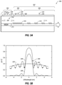
- FIG. 3D illustrates a modulation spectrum and various S21 responses of the two-kappa DBR laser of FIG. 3A ;
- FIG. 4 illustrates an example split-contact DR laser
- FIG. 5 illustrates another example two-kappa DBR laser
- FIG. 6 illustrates modulation response and PPR tunability of the split-contact DR laser of FIG. 4 .
- Uncooled 53Gbaud PAM4 (100 Gb) DBR lasers need sufficient gain length ( ⁇ 100 micrometers) to improve the high temperature performance.
- SMSR side-mode suppression ratio
- Some embodiments herein include a two-kappa DBR laser that simultaneously achieves good SMSR and high-speed operation.
- FIG. 1 illustrates an example modulation spectrum 102 of an active section of a DBR laser relative to a DBR reflection profile 104 of a DBR section of the DBR laser, arranged in accordance with at least one embodiment described herein.
- a main lasing mode 106 of the modulation spectrum 102 is aligned to a long wavelength edge 108 of a DBR reflection peak 110 of the DBR reflection profile 104 . Accordingly, lasing of the active section occurs at a frequency (or wavelength) on the long wavelength edge of the DBR stop-band.
- lasing frequency changes due to frequency chirp toward shorter wavelength as the modulation goes from the bias for the 0 bits to the bias for the 1 bits and toward longer wavelength as the modulation goes from the bias for the 1 bits to the 0 bits.
- the frequency/wavelength of the main lasing mode 106 for each of the 1 and 0 bits is designated in FIG. 1 by a corresponding vertical dashed line labeled with, respectively, a 1 or a 0.
- the frequency chirp caused by modulation results in a change in reflection as the main lasing mode 106 moves up and down the long wavelength edge of the reflection profile 104 .
- the wavelength of the main lasing mode 106 shifts toward shorter wavelength resulting in increased reflection and thus lower cavity loss.
- the wavelength of the main lasing mode 106 shifts toward longer wavelength resulting in decreased reflection and thus higher cavity loss.
- the reflectivity of the DBR region of the DBR laser at the wavelengths corresponding to each of the 1 and 0 bits is designated in FIG. 1 by a corresponding horizontal dashed line labeled with, respectively, a 1 or a 0.
- the index modulation gives rise to modulation of the cavity losses which decreases or increases the effective (netgain) modulation of the DBR laser.
- laser chirp is translated into an effective enhancement of the differential gain, and thus improves the speed of the DBR laser.
- the detuned-loading effect includes the effect(s) that occur under modulation when the lasing mode 106 is aligned to the long-wavelength edge 108 of the DBR reflection peak 108 , which may include one or more of effective enhancement of the differential gain, improved speed, and increased bandwidth.
- the slope of the long wavelength edge 108 may determine a magnitude of the detuned-loading effect. In general, the detuned-loading effect may be more pronounced for steeper slope.
- the slope of the long wavelength edge 108 and the width of the DBR stopband may be determined by the length and/or kappa of a DBR grating in the DBR section. In general, for example, longer length of the DBR section may result in steeper long wavelength edge 108 and narrower DBR stopband. Further, the narrower the DBR stopband, the better the SMSR.
- the configuration of a DBR grating with a steeper long wavelength edge 108 and narrower DBR stopband allows “reactive photons” (also referred to as “confined photons”) to penetrate relatively deeply into the DBR grating.
- Reactive photons within the active section can contribute to high speed modulation while those outside the active section do not.
- high speed modulation may be improved with improved longitudinal confinement (e.g., shallow penetration) of reactive photons relative to the DBR grating.
- Embodiments described herein may include DBR lasers with a high reflection (HR) mirror, an active section, and first and second DBR sections, each of the first and second DBR sections having a corresponding first or second DBR grating with a different corresponding first or second kappa.
- DBR lasers with two different DBR gratings having different kappas may be referred to herein as two-kappa DBR lasers.
- the active section may be positioned between the HR mirror and the first DBR section, the foregoing components forming a Fabry-Perot (FP) cavity.
- the second DBR section may be coupled to the first DBR section.
- the first DBR section may be relatively short and the first kappa may be relatively strong.
- the second DBR section may be relatively long and the second kappa may be relatively weak.
- a reflection profile of the first DBR section may have a broad DBR reflection peak with a relatively low maximum value.
- a reflection profile of the second DBR may have a relatively narrow DBR reflection peak with a relatively high maximum value and relatively steep slope on the long wavelength edge. Accordingly, the two-kappa DBR may in aggregate simultaneously have both relatively high SMSR and relatively shallow penetration depth for high-speed operation.
- Embodiments described herein may additionally leverage the photon-photon resonance (PPR) effect to improve performance.
- PPR photon-photon resonance
- a DML such as a DFB laser or DBR laser
- modulation sidebands broaden the spectrum of the DML around the main lasing mode. If the side mode of the laser cavity is present within the modulation spectrum, such sidebands can be coupled into the side mode and be resonantly amplified. This situation is depicted in FIG. 2 .
- This effect is called the PPR effect and can enhance the modulation response at around a frequency corresponding to the frequency difference between the main and side modes.
- the frequency separation between the lasing mode and the PPR mode may be referred to as the PPR frequency.
- Embodiments described herein may have a PPR frequency in a range from 20 GHz to 80 GHz or other suitable PPR frequency.
- FIG. 3A illustrates an example two-kappa DBR laser 300 , arranged in accordance with at least one embodiment described herein.
- the two-kappa DBR laser 300 includes a passive section 302 and an active section 304 .
- the passive section 302 may have a length in a range from 120 to 250 micrometers or more.
- the active section 304 may have a length in a range from 50 to 150 micrometers.
- the passive section 302 may include a first DBR section 306 and a second DBR section 308 .
- the first DBR section 306 may be coupled to a front 307 of the active section 304 .
- the second DBR section 308 may be coupled to a front 309 of the first DBR section 306 .
- the first DBR section 306 may have a first DBR grating 310 with a first kappa.
- the first DBR section 306 may be relatively short, such as 30 micrometers or less, or in a range from 10 to 30 micrometers. In the example of FIG. 3A , the length of the first DBR section 306 may be 15 micrometers. Alternatively, the first DBR section 306 may have a length in a range from 30 to 100 micrometers.
- the first kappa of the first DBR grating 310 may be relatively strong, such as at least 250 per centimeter (cm ⁇ 1 ), or more or less than 250 cm ⁇ 1 . In the example of FIG.
- the first kappa of the first DBR grating 310 may be 500 cm ⁇ 1 .
- the first DBR grating 310 may have a kappa ⁇ length, or ⁇ L value, in a range from 0.5 to 1.0.
- the first DBR grating 310 may have a length L of 15 micrometers, a kappa ⁇ of 500 cm ⁇ 1 , and a ⁇ L of 0.75.
- the second DBR section 308 may have a second DBR grating 312 with a second kappa.
- the second DBR section 306 may be relatively long, such as 120 micrometers or more, or in a range from 120 to 250 micrometers. In the example of FIG. 3A , the length of the second DBR section 308 may be 150 micrometers.
- the second kappa of the second DBR grating 312 may be less than the first kappa of the first DBR grating 310 .
- the second kappa of the second DBR grating 312 may be 80 cm ⁇ 1 or less.
- the second DBR grating 312 may have a ⁇ L value in a range from 0.5 to 1.0.
- the second DBR grating 312 may have a length L of 200 micrometers, a kappa ⁇ of 43 cm ⁇ 1 , and a ⁇ L of 0.86.
- the second DBR grating 312 includes a sampled grating with an effective kappa of 80 cm ⁇ 1 .
- the kappa of a DBR grating as used herein may refer to the effective kappa of the DBR grating which may be the same as the actual kappa in the case of a uniform grating.
- the active section 304 may include a multiple quantum well (MQW) gain layer 314 or other suitable gain layer and may be configured to operate in a lasing mode.
- MQW multiple quantum well
- the active section 304 may have a length of 50 micrometers.
- An HR mirror 316 is formed at a rear 317 , e.g., on a rear facet, of the active section 304 .
- the HR mirror 316 may be coupled to the rear 317 of the active section 304 .
- the HR mirror 316 may have a reflectivity of 30% or more.
- the HR mirror 316 , the active section 304 , and the first DBR section 306 may form a Fabry-Perot (FP) cavity 318 , which may increase a longitudinal confinement factor of the two-kappa DBR laser 300 compared to uniform (e.g., single kappa) DBR lasers.
- FP Fabry-Perot
- the two-kappa DBR laser 300 may additionally include modulation contact 322 and first and second bias contacts 324 , 326 electrically coupled to, respectively, the active section 304 , the first DBR section 306 , and the second DBR section 308 .
- a modulation signal 328 may be provided through the modulation contact 322 to the active section 304 to modulate the active section 304 .
- Modulation of the active section 304 may modulate the cavity loss of the two-kappa DBR laser 300 and may increase a carrier-photon resonance frequency (F r ) of the two-kappa DBR laser 300 .
- a first bias signal 330 may be provided through the first bias contact 324 to the first DBR section.
- a second bias signal 332 may be provided through the second bias contact 326 to the second DBR section.
- current tuning may be applied to one or both of the first and second DBR sections 306 , 308 as described elsewhere herein to tune PPR frequency of the two-kappa DBR laser 300 .
- the two-kappa DBR laser 300 may further include a low reflection (LR) mirror formed at the output facet of the second DBR section 308 to improve SMSR.
- the LR mirror may have a reflectivity of, e.g., 1% or less.
- FIG. 3B illustrates a reflection profile 334 of the first DBR section 306 (hereinafter first DBR reflection profile 334 ), a reflection profile 336 of the second DBR section 308 (hereinafter second DBR reflection profile 336 ), and a reflection profile 338 of the two-kappa DBR laser 300 as a whole (hereinafter two-kappa DBR laser reflection profile 338 ), arranged in accordance with at least one embodiment described herein.
- first DBR reflection profile 334 the first DBR section 306 has a broad DFB reflection peak with a relatively low maximum reflection.
- the second DBR reflection profile 336 the second DBR section 308 has a much narrower DFB reflection peak with relatively steep long wavelength edge.
- the two-kappa DBR laser reflection profile 338 is the aggregate reflection profile of the two-kappa DBR laser 300 from the combination of the first and second DBR reflection profiles 334 , 336 .
- the long wavelength edge of the two-kappa DBR laser reflection profile 338 is even steeper at the lasing mode 340 of the active section 304 than the long wavelength edge of the second DBR reflection profile 336 .
- the long wavelength edge of the DFB reflection peak of the two-kappa DBR laser reflection profile 338 may have a slope of at least 0.002 GHz ⁇ 1 , such as a slope of about 0.006 GHz ⁇ 1 at a lasing mode 340 of the two-kappa DBR laser 300 . In some embodiments, the slope may be in a range from 0.002 GHz ⁇ 1 to 0.009 GHz ⁇ 1 .
- FIG. 3B further illustrates a PPR mode 342 of the two-kappa DBR laser 300 .
- the PPR mode 342 may have a PPR frequency in a range of 20 GHz to 80 GHz.
- the PPR frequency may be tuned over a range by detuning the first and second DBR sections 306 , 308 relative to each other with current tuning.
- the tuning range of the PPR frequency may be 20 GHz to 80 GHz.
- FIG. 3C illustrates distributions 344 of reactive photons during lasing in three different example lasers, arranged in accordance with at least one embodiment described herein.
- the three example lasers include a distributed reflector (DR) laser as disclosed in the U.S. Pat. No. 10,063,032, a DBR laser with a uniform kappa, and the two-kappa DBR laser 300 of FIG. 3A .
- DR distributed reflector
- FIG. 3C the distributions 344 are normalized over the active section.
- Labels e.g., “MQW” and “DBR”, and arrows across the top of the graph of the distributions 344 indicate the locations of the MQW or active region and of a DBR region (made up of the first and second DBR sections 306 , 308 in the case of the two-kappa DBR laser 300 ) in all three example lasers.
- the distributions 344 include a distribution 344 A of the DR laser, a distribution 344 B of the two-kappa DBR laser 300 , and a distribution 344 C of the DBR laser with a uniform kappa.
- a region 344 D in the DBR section corresponds to the first DBR section 306 of the two-kappa DBR laser 300 , with a remainder of the DBR section in the distribution 344 B corresponding to the second DBR section 308 .
- the first DBR section 306 generally confines the reactive photons to the active section 304 .
- the distribution 344 B of reactive photons drops significantly from the active section 304 through the first DBR section 306 to the second DBR section 308 .
- the distribution 344 of reactive photons may drop by at least 50% through the first DBR section 306 from the active section 304 to the second DBR section 308 .
- significantly more light penetrates into the passive/DBR section of the DBR laser with uniform kappa, which dilutes differential gain and slows the DBR laser with uniform kappa.
- FIG. 3D illustrates a modulation spectrum 346 and various S21 responses 348 of the two-kappa DBR laser 300 of FIG. 3A , arranged in accordance with at least one embodiment described herein.
- the modulation spectrum 346 includes the lasing mode 340 and the PPR mode 342 .
- the frequency difference between the lasing mode 340 and the PPR mode 342 may be referred to as the PPR frequency.
- the PPR frequency appears in the S21 responses 348 as the peaks at around 60 GHz.
- Embodiments of the two-kappa DBR laser 300 with a 50 micrometer active section 304 may have a 3 dB bandwidth at room temperature of about 30 GHz or more such as 35 GHz for 50 Gbaud PAM4, or even 60 GHz or more such as 65 GHz.
- Embodiments of the two-kappa DBR laser 300 with a 100 micrometer active section 304 may have a 3 dB bandwidth at 70 C of 50 GHz or more.
- FIG. 4 illustrates an example split-contact DR laser 400 , arranged in accordance with at least one embodiment described herein.
- the split-contact DR laser 400 includes a passive section 402 and an active section 404 .
- the passive section 402 may have a length of about 215 micrometers or other suitable length.
- the active section 404 may have a length of about 50 micrometers or other suitable length.
- the passive section 402 includes a DBR grating 406 , e.g., with a uniform kappa.
- the active section includes a DFB grating 408 formed in or above an active region, such as in or above a MQW layer 410 .
- An HR mirror 412 also referred to as a rear mirror, is formed on a rear facet of the active section 404 .
- the HR mirror 412 may have a reflectivity of 30% or more.
- An antireflection (AR) coating 414 may be formed on a front facet of the passive section 402 .
- the split-contact DR laser 400 may additionally include modulation contact 416 and first and second bias contacts 418 , 420 .
- the modulation contact 416 is electrically coupled to the active section 404 .
- the first bias contact 418 is electrically coupled to a first portion of the passive section 402 that may have a length of about 140 micrometers.
- the second bias contact 420 is electrically coupled to a second portion of the passive section 402 that may have a length of about 75 micrometers.
- a modulation signal 422 may be provided through the modulation contact 416 to the active section 404 .
- a first bias signal 424 may be provided through the first bias contact 418 to the first portion of the passive section 402 .
- a second bias signal 426 may be provided through the second bias contact 420 to the second portion of the passive section.
- Current tuning may be applied to one or both of the first and second bias contacts 418 , 420 to tune PPR frequency of the split-contact DR laser 400 .
- the first and second portions of the passive section 402 may be tuned relative to each other to tune the PPR frequency of the split-contact DR laser 400 .
- FIG. 5 illustrates another example two-kappa DBR laser 500 , arranged in accordance with at least one embodiment described herein.
- the two-kappa DBR laser 500 includes a passive section 502 , an active section 504 , and optionally a semiconductor optical amplifier (SOA) section 506 .
- the passive section 502 may have a length of about 215 micrometers or other suitable length.
- the active section 504 may have a length of about 50 micrometers or other suitable length.
- the passive section 502 and the active section 504 may be the same as or similar to the passive section 302 and the active section 304 of the two-kappa DBR laser 300 of FIG. 3 except as otherwise noted herein.
- the passive section 502 may include a first DBR section 508 and a second DBR section 510 .
- the first DBR section 508 may have a first DBR grating 512 with a first kappa.
- the length of the first DBR section 508 may be 15 micrometers or other suitable length.
- the second DBR section 510 may have a second DBR grating 514 with a second kappa that is different and less than the first kappa.
- the length of the second DBR section 510 may be 200 micrometers or other suitable length.
- the active section 504 includes an active region such as a MQW layer 516 .
- An HR mirror 518 also referred to as a rear mirror, is formed at a rear 519 , e.g., on a rear facet, of the active section 504 .
- the HR mirror 518 may be coupled to the rear 519 of the active section 504 .
- the HR mirror 518 may have a reflectivity of 30% or more.
- An antireflection (AR) coating 520 may be formed at a front 521 , e.g., on a front facet of, the SOA section 506 .
- the AR coating 520 may be coupled to the front 521 of the SOA section 506 .
- the two-kappa DBR laser 500 may additionally include modulation contact 522 , first bias contact 524 , second bias contact 526 , third bias contact 528 , and fourth bias contact 530 .
- the modulation contact 522 is electrically coupled to the active section 504 .
- the first bias contact 524 is electrically coupled to the first DBR section 508 .
- the second bias contact 526 is electrically coupled to a first portion of the second DBR section 510 that may have a length of about 140 micrometers or other suitable length.
- the third bias contact 528 is electrically coupled to a second portion of the second DBR section 510 may have a length of about 60 micrometers or other suitable length.
- the fourth bias contact 530 is electrically coupled to the SOA section 506 .
- the second DBR section 510 has a split contact, e.g., the second and third bias contacts 526 , 528 , as opposed to a single bias contact (e.g., the second bias contact 326 ) for the second DBR section 308 of FIG. 3 .
- the two-kappa DBR laser 500 may be referred to as a split-contact two-kappa DBR laser 500 .
- a modulation signal 532 may be provided through the modulation contact 522 to the active section 504 .
- Modulation of the active section 504 may modulate the cavity loss of the two-kappa DBR laser 500 and may increase a F r of the two-kappa DBR laser 500 .
- a first bias signal 534 may be provided through the first bias contact 524 to the first DBR section 508 .
- a second bias signal 536 may be provided through the second bias contact 526 to the first portion of the second DBR section 510 .
- a third bias signal 538 may be provided through the third bias contact 528 to the second portion of the second DBR section 510 .
- a fourth bias signal 540 and/or a modulation signal may be provided through the fourth bias contact 530 to SOA section 506 .
- Current tuning may be applied to one or both of the second and third bias contacts 526 , 528 to tune PPR frequency of the two-kappa DBR laser 500 .
- the first and second portions of the second DBR section 510 of the passive section 502 may be tuned relative to each other to tune the PPR frequency of the two-kappa DBR laser 500 .
- FIG. 6 illustrates modulation response 602 and PPR tunability 604 of the split-contact DR laser 400 of FIG. 4 , arranged in accordance with at least one embodiment described herein.
- Split-contact two-kappa DBR lasers such as the two-kappa DBR laser 500 of FIG. 5 , may similarly have PPR tunability.
- the split-contact DR laser 400 may have a F r of about 25 GHz.
- the PPR frequency of the split-contact DR laser 400 may be tuned between 20 GHz to 80 GHz by application of an appropriate combination of gain bias and current tuning to one or more of the first portion of the passive section 402 (referred to as “DBR1 in FIG. 6 ”) and the second portion of the passive section 402 (referred to as “DBR2” in FIG. 6 ).
- the PPR frequency is in a range from about 81 GHz to about 71 GHz as depicted by the topmost curve (e.g., the curve marked with elliptical points) of the PPR tunability 604 .
- the PPR frequency is in a range from about 71 GHz to about 55 GHz as depicted by the next curve (e.g., the curve marked with x points) below the topmost curve of the PPR tunability 604 .
Abstract
Description
Claims (20)
Priority Applications (3)
| Application Number | Priority Date | Filing Date | Title |
|---|---|---|---|
| US16/691,553 US11233375B2 (en) | 2019-10-01 | 2019-11-21 | Two-kappa DBR laser |
| DE102020125578.0A DE102020125578B4 (en) | 2019-10-01 | 2020-09-30 | TWO-KAPPA DBR LASER |
| CN202011071998.6A CN112600071A (en) | 2019-10-01 | 2020-10-09 | Double-kappa distributed Bragg reflector laser |
Applications Claiming Priority (3)
| Application Number | Priority Date | Filing Date | Title |
|---|---|---|---|
| US201962908990P | 2019-10-01 | 2019-10-01 | |
| US201962938151P | 2019-11-20 | 2019-11-20 | |
| US16/691,553 US11233375B2 (en) | 2019-10-01 | 2019-11-21 | Two-kappa DBR laser |
Publications (2)
| Publication Number | Publication Date |
|---|---|
| US20210098969A1 US20210098969A1 (en) | 2021-04-01 |
| US11233375B2 true US11233375B2 (en) | 2022-01-25 |
Family
ID=75155695
Family Applications (1)
| Application Number | Title | Priority Date | Filing Date |
|---|---|---|---|
| US16/691,553 Active 2040-08-03 US11233375B2 (en) | 2019-10-01 | 2019-11-21 | Two-kappa DBR laser |
Country Status (2)
| Country | Link |
|---|---|
| US (1) | US11233375B2 (en) |
| DE (1) | DE102020125578B4 (en) |
Families Citing this family (1)
| Publication number | Priority date | Publication date | Assignee | Title |
|---|---|---|---|---|
| CN113328339B (en) * | 2021-05-27 | 2022-11-25 | 华中科技大学 | High-power distributed feedback laser |
Citations (12)
| Publication number | Priority date | Publication date | Assignee | Title |
|---|---|---|---|---|
| US4908833A (en) | 1989-01-27 | 1990-03-13 | American Telephone And Telegraph Company | Distributed feedback laser for frequency modulated communication systems |
| US20050238079A1 (en) | 2002-01-18 | 2005-10-27 | Wisconsin Alumni Research Foundation | High coherent power, two-dimensional surface-emitting semiconductor diode array laser |
| EP1850429A1 (en) * | 2006-04-28 | 2007-10-31 | Alcatel Lucent | Laser emission device with distributed reflectors |
| KR20100072534A (en) * | 2008-12-22 | 2010-07-01 | 한국전자통신연구원 | Semeconductor laser device |
| US20100265980A1 (en) | 2009-04-17 | 2010-10-21 | Fujitsu Limited | Semiconductor laser |
| US20100272133A1 (en) | 2009-04-27 | 2010-10-28 | Sumitomo Electric Industries, Ltd. | Wavelength tunable laser |
| US20110299561A1 (en) | 2009-03-05 | 2011-12-08 | Fujitsu Limited | Semiconductor laser silicon waveguide substrate, and integrated device |
| US20130308178A1 (en) | 2012-05-17 | 2013-11-21 | Finisar Corporation | Co-modulation of DBR Laser and Integrated Optical Amplifier |
| US20140269807A1 (en) | 2013-03-12 | 2014-09-18 | Finisar Corporation | Short gain cavity distributed bragg reflector laser |
| US20160064897A1 (en) | 2014-08-29 | 2016-03-03 | Fujitsu Optical Components Limited | Semiconductor laser |
| US20160164257A1 (en) | 2014-12-09 | 2016-06-09 | Oclaro Japan, Inc. | Semiconductor integrated optical device, manufacturing method thereof and optical module |
| US10063032B2 (en) | 2016-03-06 | 2018-08-28 | Finisar Corporation | Distributed reflector laser |
-
2019
- 2019-11-21 US US16/691,553 patent/US11233375B2/en active Active
-
2020
- 2020-09-30 DE DE102020125578.0A patent/DE102020125578B4/en active Active
Patent Citations (12)
| Publication number | Priority date | Publication date | Assignee | Title |
|---|---|---|---|---|
| US4908833A (en) | 1989-01-27 | 1990-03-13 | American Telephone And Telegraph Company | Distributed feedback laser for frequency modulated communication systems |
| US20050238079A1 (en) | 2002-01-18 | 2005-10-27 | Wisconsin Alumni Research Foundation | High coherent power, two-dimensional surface-emitting semiconductor diode array laser |
| EP1850429A1 (en) * | 2006-04-28 | 2007-10-31 | Alcatel Lucent | Laser emission device with distributed reflectors |
| KR20100072534A (en) * | 2008-12-22 | 2010-07-01 | 한국전자통신연구원 | Semeconductor laser device |
| US20110299561A1 (en) | 2009-03-05 | 2011-12-08 | Fujitsu Limited | Semiconductor laser silicon waveguide substrate, and integrated device |
| US20100265980A1 (en) | 2009-04-17 | 2010-10-21 | Fujitsu Limited | Semiconductor laser |
| US20100272133A1 (en) | 2009-04-27 | 2010-10-28 | Sumitomo Electric Industries, Ltd. | Wavelength tunable laser |
| US20130308178A1 (en) | 2012-05-17 | 2013-11-21 | Finisar Corporation | Co-modulation of DBR Laser and Integrated Optical Amplifier |
| US20140269807A1 (en) | 2013-03-12 | 2014-09-18 | Finisar Corporation | Short gain cavity distributed bragg reflector laser |
| US20160064897A1 (en) | 2014-08-29 | 2016-03-03 | Fujitsu Optical Components Limited | Semiconductor laser |
| US20160164257A1 (en) | 2014-12-09 | 2016-06-09 | Oclaro Japan, Inc. | Semiconductor integrated optical device, manufacturing method thereof and optical module |
| US10063032B2 (en) | 2016-03-06 | 2018-08-28 | Finisar Corporation | Distributed reflector laser |
Non-Patent Citations (9)
| Title |
|---|
| Chacinski, et al., "Effects of detuned loading on the modulation performance of widely tunable MG-Y lasers," Proc. SPIE 6997, Semiconductor Lasers and Laser Dynamics III, 699709 (May 8, 2008) 9 pgs. |
| Dumitrescu, et al., "Distributed Feedback Lasers with Photon-Photon-Resonance-Enhanced Modulation Bandwidth" Semiconductor Conference, 2012 International IEEE, Oct. 15, 2012, 4 pgs. |
| International Search Report and Written Opinion for International Application No. PCT/US2017/021014, dated May 12, 2017, 15 pgs. |
| Machine translation of EP 1850429 A1 (Year: 2007). * |
| Machine translation of KR 20100072534 A (Year: 2010). * |
| Matsui—Book, Datacenter Connectivity Technologies: Principles and Practice, ISBN 9788793609228, River Publishers Series in Optics and Photonics, Chapter 3—"Directly Modulated Laser Technology: Past, Present, Future" River Publishers Oct. 8, 2018 (86 Pgs.). |
| Radziunas, et al., "Improving the Modulation Bandwidth in Semiconductor Lasers by passive Feedback," IEEE Journal of Selected Topics in Quantum Electronics, IEEE Service Center, vol. 13, No. 1, Jan. 1, 2007, 8 pgs. |
| Troppenz, et al., "40 Gbit/s Directly Modulated Lasers: Physics and Application" Proc. SPIE 7953, Novel In-Plane Semiconductor Lasers X, 79530F (Feb. 16, 2011) 10 pgs. |
| Yamaoka, et al. "239.3-Gbit/s Net Rate PAM-4 Transmission Using Directly Modulated Membrane Lasers on High-Thermal-Conductivity SiC" The 45th European Conference on Optical Communication, Dublin, Sep. 22-26, 2019 4pgs. |
Also Published As
| Publication number | Publication date |
|---|---|
| DE102020125578B4 (en) | 2022-12-01 |
| DE102020125578A1 (en) | 2021-04-15 |
| US20210098969A1 (en) | 2021-04-01 |
Similar Documents
| Publication | Publication Date | Title |
|---|---|---|
| US10944241B2 (en) | Distributed reflector laser | |
| US5648978A (en) | Oscillation polarization mode selective semiconductor laser, modulation method therefor and optical communication system using the same | |
| US8213804B2 (en) | Semiconductor optical amplifier for an external cavity diode laser | |
| US6519270B1 (en) | Compound cavity reflection modulation laser system | |
| JP2007158057A (en) | Integrated laser device | |
| WO2019235235A1 (en) | Optical transmitter and multi-wavelength optical transmitter | |
| US11233375B2 (en) | Two-kappa DBR laser | |
| US8594469B2 (en) | Optical amplifier | |
| Kim et al. | 10 Gbps SOA-REAM using monolithic integration of planar buried-heterostructure SOA with deep-ridge waveguide EA modulator for colourless optical source in WDM-PON | |
| CN112600071A (en) | Double-kappa distributed Bragg reflector laser | |
| US20210098970A1 (en) | Isolator-free laser | |
| US11251585B2 (en) | DFB with weak optical feedback | |
| JP3246703B2 (en) | Semiconductor laser capable of polarization modulation and optical communication system using the same | |
| Levaufre et al. | Hybrid III-V/silicon tunable laser directly modulated at 10Gbit/s for short reach/access networks | |
| KR102452873B1 (en) | Optical transmitter | |
| Zhang et al. | Widely tunable electro-absorption modulated V-cavity laser | |
| CN109196739B (en) | Chirp compensation laser and driving method thereof | |
| Lopera et al. | Design of a colorless transmitter based on a low-resonant Fabry–Perot Laser for applications in WDM-PON | |
| JP7107180B2 (en) | Multi-wavelength optical transmitter | |
| US20240047939A1 (en) | Bandwith enhanced dfb+r lite laser | |
| JP2018206901A (en) | Optical transmitter | |
| JP3287443B2 (en) | Semiconductor laser capable of polarization modulation and optical communication system using the same | |
| Kobayashi et al. | Full $ C $-Band 10-Gb/s 40-km SMF Transmission of InGaAlAs Electroabsorption Modulator | |
| Gu et al. | Direct Modulation Bandwidth Enhancement in Two-section DFB Lasers with Phase-shifted Grating Reflector Based on the Detuned-Loading Effect | |
| KR100405940B1 (en) | Laterally coupled cavity laser diode |
Legal Events
| Date | Code | Title | Description |
|---|---|---|---|
| FEPP | Fee payment procedure |
Free format text: ENTITY STATUS SET TO UNDISCOUNTED (ORIGINAL EVENT CODE: BIG.); ENTITY STATUS OF PATENT OWNER: LARGE ENTITY |
|
| AS | Assignment |
Owner name: II-VI DELAWARE, INC., DELAWARE Free format text: ASSIGNMENT OF ASSIGNORS INTEREST;ASSIGNOR:MATSUI, YASUHIRO;REEL/FRAME:051097/0172 Effective date: 20191121 |
|
| STPP | Information on status: patent application and granting procedure in general |
Free format text: DOCKETED NEW CASE - READY FOR EXAMINATION |
|
| AS | Assignment |
Owner name: II-VI DELAWARE, INC., DELAWARE Free format text: ASSIGNMENT OF ASSIGNORS INTEREST;ASSIGNOR:FINISAR CORPORATION;REEL/FRAME:052286/0001 Effective date: 20190924 |
|
| STPP | Information on status: patent application and granting procedure in general |
Free format text: NOTICE OF ALLOWANCE MAILED -- APPLICATION RECEIVED IN OFFICE OF PUBLICATIONS |
|
| STPP | Information on status: patent application and granting procedure in general |
Free format text: PUBLICATIONS -- ISSUE FEE PAYMENT VERIFIED |
|
| STCF | Information on status: patent grant |
Free format text: PATENTED CASE |
|
| AS | Assignment |
Owner name: JPMORGAN CHASE BANK, N.A., AS COLLATERAL AGENT, NEW YORK Free format text: SECURITY INTEREST;ASSIGNORS:II-VI INCORPORATED;II-VI DELAWARE, INC.;M CUBED TECHNOLOGIES, INC.;AND OTHERS;REEL/FRAME:060562/0254 Effective date: 20220701 |