US11233290B2 - Battery holder capable of simplifying assembly procedure - Google Patents

Battery holder capable of simplifying assembly procedure Download PDF

Info

Publication number
US11233290B2
US11233290B2 US16/432,856 US201916432856A US11233290B2 US 11233290 B2 US11233290 B2 US 11233290B2 US 201916432856 A US201916432856 A US 201916432856A US 11233290 B2 US11233290 B2 US 11233290B2
Authority
US
United States
Prior art keywords
battery
anode
cathode
chambers
battery chambers
Prior art date
Legal status (The legal status is an assumption and is not a legal conclusion. Google has not performed a legal analysis and makes no representation as to the accuracy of the status listed.)
Active, expires
Application number
US16/432,856
Other versions
US20200136103A1 (en
Inventor
Dah-Luen Huang
Current Assignee (The listed assignees may be inaccurate. Google has not performed a legal analysis and makes no representation or warranty as to the accuracy of the list.)
HUANG DAH LUEN
Original Assignee
Dah-Luen Huang
Priority date (The priority date is an assumption and is not a legal conclusion. Google has not performed a legal analysis and makes no representation as to the accuracy of the date listed.)
Filing date
Publication date
Priority claimed from TW107214462U external-priority patent/TWM573901U/en
Priority claimed from TW108206024U external-priority patent/TWM584988U/en
Application filed by Dah-Luen Huang filed Critical Dah-Luen Huang
Publication of US20200136103A1 publication Critical patent/US20200136103A1/en
Application granted granted Critical
Publication of US11233290B2 publication Critical patent/US11233290B2/en
Active legal-status Critical Current
Adjusted expiration legal-status Critical

Links

Images

Classifications

    • HELECTRICITY
    • H01ELECTRIC ELEMENTS
    • H01MPROCESSES OR MEANS, e.g. BATTERIES, FOR THE DIRECT CONVERSION OF CHEMICAL ENERGY INTO ELECTRICAL ENERGY
    • H01M50/00Constructional details or processes of manufacture of the non-active parts of electrochemical cells other than fuel cells, e.g. hybrid cells
    • H01M50/20Mountings; Secondary casings or frames; Racks, modules or packs; Suspension devices; Shock absorbers; Transport or carrying devices; Holders
    • H01M50/204Racks, modules or packs for multiple batteries or multiple cells
    • H01M50/207Racks, modules or packs for multiple batteries or multiple cells characterised by their shape
    • H01M50/213Racks, modules or packs for multiple batteries or multiple cells characterised by their shape adapted for cells having curved cross-section, e.g. round or elliptic
    • HELECTRICITY
    • H01ELECTRIC ELEMENTS
    • H01MPROCESSES OR MEANS, e.g. BATTERIES, FOR THE DIRECT CONVERSION OF CHEMICAL ENERGY INTO ELECTRICAL ENERGY
    • H01M50/00Constructional details or processes of manufacture of the non-active parts of electrochemical cells other than fuel cells, e.g. hybrid cells
    • H01M50/20Mountings; Secondary casings or frames; Racks, modules or packs; Suspension devices; Shock absorbers; Transport or carrying devices; Holders
    • H01M50/204Racks, modules or packs for multiple batteries or multiple cells
    • HELECTRICITY
    • H01ELECTRIC ELEMENTS
    • H01MPROCESSES OR MEANS, e.g. BATTERIES, FOR THE DIRECT CONVERSION OF CHEMICAL ENERGY INTO ELECTRICAL ENERGY
    • H01M50/00Constructional details or processes of manufacture of the non-active parts of electrochemical cells other than fuel cells, e.g. hybrid cells
    • H01M50/20Mountings; Secondary casings or frames; Racks, modules or packs; Suspension devices; Shock absorbers; Transport or carrying devices; Holders
    • H01M50/289Mountings; Secondary casings or frames; Racks, modules or packs; Suspension devices; Shock absorbers; Transport or carrying devices; Holders characterised by spacing elements or positioning means within frames, racks or packs
    • YGENERAL TAGGING OF NEW TECHNOLOGICAL DEVELOPMENTS; GENERAL TAGGING OF CROSS-SECTIONAL TECHNOLOGIES SPANNING OVER SEVERAL SECTIONS OF THE IPC; TECHNICAL SUBJECTS COVERED BY FORMER USPC CROSS-REFERENCE ART COLLECTIONS [XRACs] AND DIGESTS
    • Y02TECHNOLOGIES OR APPLICATIONS FOR MITIGATION OR ADAPTATION AGAINST CLIMATE CHANGE
    • Y02EREDUCTION OF GREENHOUSE GAS [GHG] EMISSIONS, RELATED TO ENERGY GENERATION, TRANSMISSION OR DISTRIBUTION
    • Y02E60/00Enabling technologies; Technologies with a potential or indirect contribution to GHG emissions mitigation
    • Y02E60/10Energy storage using batteries

Definitions

  • the present invention relates to a battery holder, especially to a battery holder capable of simplifying assembly procedure.
  • the battery has been developed for a long time. By utilizing the battery which stores DC power in a columnar body, users are provided with great convenience in operating some electronic products without being limited to a conventional AC power.
  • the battery holder is integrated into an electronic product, for example a toy, a portable radio or a flashlight, and in other cases, the battery holder is designed to be separable from an electronic product.
  • the wiring circuit in the battery holder is mostly configured to provide a serial connection of batteries, but it could be also configured to provide a parallel connection of batteries for some applications.
  • FIG. 1 which is a perspective exploded view illustrating a conventional battery holder; the battery holder includes a case body 1 having at least three battery chambers 11 , and a partition plate 12 is provided between every two of the adjacent battery chambers 11 for partition, a connection assembly 2 is assembled by at least one anode/cathode connecting unit 21 disposed in the at least three battery chambers 11 , a flexible hook-up wire 24 coupled to an anode contact point 22 and a cathode contact point 23 , an anode output terminal 25 and a cathode output terminal 26 .
  • the anode output terminal 25 has an anode conduction hook-up wire 251
  • the cathode output terminal 26 has a cathode conduction hook-up wire 261 ;
  • the anode conduction hook-up wire 251 and the cathode conduction hook-up wire 261 are protruded out from a penetrated hole 13 respectively formed in the two adjacently battery chambers 11 , so that the anode conduction hook-up wire 251 and the cathode conduction hook-up wire 261 are adjacently arranged for being conveniently connected to the electronic product to supply DC power to the electronic product, and a lot of conveniences are provided to the users.
  • a bottom surface of the case body 1 is formed with an accommodation slot 14 communicated with the anode contact point 22 and the cathode contact point 23 and allowing the flexible hook-up wire 24 to be accommodated.
  • the case body 1 is reversely disposed, then two distal ends of the flexible hook-up wire 24 are respectively disposed with a combination padding coil 241 , the one end of the flexible hook-up wire 24 is inserted into a communication slot 141 and riveted with the anode contact point 22 (or the cathode contact point 23 ), another end of the flexible hook-up wire 24 is inserted into another communication slot 141 and riveted with the cathode contact point 23 (or the anode contact point 22 ), so that the flexible hook-up wire 24 is able to be accommodated in the accommodation slot 141 , thereby finishing a jumping installing procedure.
  • the operator has be reversely dispose the case body 1 then normally dispose, if the operator is careless, the flexible hook-up wire 24 may be easily fallen out from the accommodation slot 14 , and the installing procedure of the flexible hook-up wire 24 has to be repeated.
  • the combination padding coils 241 at the two distal ends of the flexible hook-up wire 24 cannot be easily aligned with two connection holes 15 allowing the anode contact point 22 and the cathode contact point 23 to be respectively riveted and positioned, so that the assembly is difficult, and unnecessary labor and working hours are wasted; accordingly, the above-mentioned disadvantages shall be improved.
  • One primary objective of the present invention is to provide a battery holder capable of simplifying assembly procedure, in which an anode/cathode jumping unit made of a rigid metal wire, for example a steel spring wire, is utilized for replacing a conventional assembly consisted of the anode contact point, the cathode contact point and the flexible hook-up wire, and the anode/cathode jumping unit is installed from a top end of the case body, thereby overcoming disadvantages of the battery holder being reversely disposed and a hole alignment operation being difficult to be processed.
  • an anode/cathode jumping unit made of a rigid metal wire, for example a steel spring wire
  • a battery holder capable of simplifying assembly procedure, which includes a case body and a connection assembly; the case body has at least three battery chambers, the connection assembly has at least one anode/cathode connecting unit, an anode output terminal, a cathode output terminal and an anode/cathode jumping unit, thereby allowing the at least three battery chambers to be in a serial connecting status;
  • the battery holder is characterized in that: an accommodation slot is formed between two of the at least three battery chambers which are arranged at outer sides, the anode/cathode jumping unit is formed through a metal wire being bent, and has a connection segment accommodated in the accommodation slot, one end of the connection segment has a cathode elastic contact point connected to the battery chamber arranged at the outer side, and another end thereof has an anode contact point connected to the other battery chamber arranged at the outer side.
  • the accommodation slot is transversally disposed on a bottom surface defined between the two battery chambers arranged at the outer sides, and two ends of the accommodation slot are respectively formed with a communication slot at locations corresponding to the two battery chambers arranged at the outer sides and allowing the anode contact point to pass.
  • the accommodation slot is transversally disposed on a top surface defined between the two battery chambers arranged at the outer sides; wherein a partition plate is provided between every two adjacent battery chambers for partition, wherein the partition plate is perpendicular to the accommodation slot, and a position corresponding to an anode protrusion of a battery located between every two adjacent partition plates and above the case body is vertically extended with a pair of abutting sheets allowing the anode protrusion to pass there between.
  • the accommodation slot is transversally disposed on a top surface defined between the two battery chambers arranged at the outer sides; wherein a partition plate is provided between every two of the adjacent battery chambers for partition, a plate slot is respectively formed at a location defined between the two battery chambers arranged at the outer sides and at a location defined at the partition plate arranged at a same side with respect to the accommodation slot, and each of the plate slots allows the anode contact point to transversally pass.
  • the accommodation slot is diagonally disposed on a top surface defined between the two battery chambers arranged at the outer sides; wherein a partition plate is provided between every two of the adjacent battery chambers for partition, each of the partition plates is longitudinally formed with a crossed slot, in a opened status, at a path where the accommodation slot passes, so that the connection segment is able to longitudinally pass each of the crossed slots so as to be accommodated in the accommodation slot.
  • the accommodation slot is diagonally disposed on a top surface defined between the two battery chambers arranged at the outer sides; wherein a partition plate is provided between every two of the adjacent battery chambers for partition, each of the partition plates is longitudinally formed with a penetrated slot, in a closed status, at a path where the accommodation slot passes, so that the connection segment is able to transversally pass each of the penetrated slots so as to be accommodated in the accommodation slot.
  • the metal wire is a steel spring wire;
  • the anode contact point has a frame member formed in a geometrical shape; and the frame member is formed in a rectangular shape or an annular shape.
  • a partition plate is provided between every two of the adjacent battery chambers for partition, and a hanging segment, which can be communicated with each other, is integrally disposed at a location defined between the partition plates disposed corresponding to each of the anode/cathode connecting units and the case body, thereby allowing each of the anode/cathode connecting units to be in a hanging status.
  • the anode output terminal has an anode conduction hook-up wire
  • the cathode output terminal has a cathode conduction hook-up wire
  • the anode conduction hook-up wire and the cathode conduction hook-up wire are protruded out from a penetrated hole respectively formed in the two adjacently battery chambers, so that the anode conduction hook-up wire and the cathode conduction hook-up wire are adjacently arranged.
  • FIG. 1 is a perspective exploded view illustrating a conventional battery holder
  • FIG. 2 is a perspective view illustrating the assembly of the battery holder of FIG. 1 ;
  • FIG. 3 is a perspective exploded view illustrating a battery holder according to a first embodiment of the present invention
  • FIG. 4 is a perspective view illustrating the assembly of the battery holder of FIG. 3 ;
  • FIG. 5 is a perspective view illustrating the battery holder being reversely disposed according to the first embodiment of the present invention
  • FIG. 6 is a perspective exploded view illustrating the battery holder according to a second embodiment of the present invention.
  • FIG. 7 is a perspective view illustrating the assembly of the battery holder of FIG. 6 ;
  • FIG. 8 is a top view illustrating the assembly of the battery holder according to the second embodiment of the present invention.
  • FIG. 9 is a perspective exploded view illustrating the battery holder according to a third embodiment of the present invention.
  • FIG. 10 is a perspective view illustrating the assembly of the battery holder of FIG. 9 ;
  • FIG. 11 is a top view illustrating the assembly of the battery holder according to the third embodiment of the present invention.
  • FIG. 12 is a perspective exploded view illustrating the battery holder according to a fourth embodiment of the present invention.
  • FIG. 13 is a perspective view illustrating the assembly of the battery holder of FIG. 12 ;
  • FIG. 14 is a cross sectional view of FIG. 13 taken along an A-A line;
  • FIG. 15 is a cross sectional view of FIG. 13 taken along a B-B line;
  • FIG. 16 is a perspective exploded view illustrating the battery holder according to a fifth embodiment of the present invention.
  • FIG. 17 is a perspective view illustrating the assembly of the battery holder of FIG. 16 .
  • a battery holder including a case body 1 and a connection assembly 2 is provided according to a first embodiment of the present invention.
  • the case body 1 is substantially the same as a conventional case body, and has at least three battery chambers 11 as shown in FIG. 3 , the quantity of the at least three battery chambers 11 is an even number equal to or greater than three, for example four battery chambers 11 ; and a partition plate 12 is disposed between every two of the adjacent battery chambers 11 for partition, the connection assembly 2 is disposed in the at least three battery chambers 11 , the connection assembly 2 has at least one anode/cathode connecting unit 21 , an anode output terminal 25 , a cathode output terminal 26 and an anode/cathode jumping unit 27 , thereby allowing the at least three battery chambers 11 to be in a serial connecting status.
  • the anode output terminal 25 has an anode conduction hook-up wire 251
  • the cathode output terminal 26 has a cathode conduction hook-up wire 261
  • the anode conduction hook-up wire 251 and the cathode conduction hook-up wire 261 are protruded out from a penetrated hole 13 respectively formed in the two adjacently-arranged battery chambers 11 , so that the anode conduction hook-up wire 251 and the cathode conduction hook-up wire 261 are adjacently arranged for being conveniently connected to an electronic product to supply DC power to the electronic product.
  • the anode/cathode jumping unit 27 is formed through a metal wire, for example a steel spring wire, being bent, and the anode/cathode jumping unit 27 has a connection segment 271 , one end of the connection segment 271 has a cathode elastic contact point 272 connected to the battery chamber 11 arranged at the outer side, and another end thereof has the anode contact point 273 connected to the other battery chamber 11 arranged at the outer side.
  • the anode contact point 273 has a frame member formed in a geometrical shape, for example a rectangular shape (as shown in FIG. 3 , FIG. 6 and FIG. 9 ) or an annular shape (as shown in FIG. 12 and FIG. 16 ).
  • the anode/cathode jumping unit 27 is formed through a metal wire being bent, and provided with a certain rigidity; when being assembled, the anode contact point 273 firstly passes through one of the communication slots 141 formed at one of the battery chambers 11 at arranged at the outer sides then penetrates out from the other communication slot 141 of the other battery chamber 11 arranged at the outer sides, so that the connection segment 271 is able to be accommodated in the accommodation slot 14 , and the cathode elastic contact point 272 is riveted in a connection hole 15 of the case body 1 , then the anode contact point 273 is riveted in another connection hole 15 of the case body 1 , so that the at least one anode/cathode connecting unit 21 , the anode output terminal 25 , the cathode output terminal 26 and the at least one anode/cathode jumping unit 27 are assembled as the connection assembly 2 .
  • the anode/cathode jumping unit 27 is installed from a top end of the case body 1 , thus the complicated assembly procedure of the battery holder being reversely disposed and a hole alignment operation being difficult to be processed are overcome, and objectives of saving labor and saving working hours are achieved.
  • FIG. 6 to FIG. 8 discloses a second embodiment of the battery holder, the same components shared by the second embodiment and the first embodiment are provided with the codes, because there are a lot of the components shared by the second embodiment and the first embodiment, only differences between the two embodiments are illustrated as follows.
  • a top surface defined between the two battery chambers 11 arranged at the outer sides of the case body 1 is transversally formed with an accommodation slot 14 allowing the anode/cathode jumping unit 27 to be installed; as such, the two communication slots 141 disclosed in the first embodiment are not required in the second embodiment.
  • Advantages achieved by this embodiment are that the accommodation slot 14 is formed inside the case body 1 , so that dangers caused by a short circuit status on a bottom surface of the case body 1 can be prevented.
  • the partition plate 12 arranged between every two adjacent battery chambers 11 is perpendicular to the accommodation slot 14 , and a position corresponding to an anode protrusion (known as prior art therefore not shown in figures) of a battery located between every two adjacent partition plates 12 and above the case body 1 is vertically extended with a pair of abutting sheets 121 allowing the anode protrusion to pass therebetween, so that the anode protrusion is able to be in contact with the anode contact point 273 or the anode/cathode connecting unit 21 .
  • FIG. 9 to FIG. 11 discloses a third embodiment of the battery holder, the same components shared by the third embodiment and the first embodiment are provided with the codes, because there are a lot of the components shared by the third embodiment and the first embodiment, only differences between the two embodiments are illustrated as follows.
  • the quantity of the at least three battery chambers 11 is an odd number equal to or greater than three, for example three battery chambers 11 , a top surface defined between the two battery chambers 11 arranged at the outer sides of the case body 1 is diagonally formed with an accommodation slot 14 allowing the anode/cathode jumping unit 27 to be installed.
  • the accommodation slot 14 is formed inside the case body 1 , so that dangers caused by a short circuit status on a bottom surface of the case body 1 can be prevented.
  • the partition plate 12 is arranged between every two of the adjacent battery chambers 11 in the case body 1 , the partition plate 12 is longitudinally formed with a crossed slot 122 , in an opened status, at a path where the accommodation slot 14 passes, so that the connection segment 271 is able to longitudinally pass each of the crossed slots 122 so as to be accommodated in the accommodation slot 14 .
  • FIG. 12 to FIG. 15 discloses a fourth embodiment of the battery holder
  • the same components shared by the fourth embodiment and the second embodiment are provided with the codes, because there are a lot of the components shared by the fourth embodiment and the second embodiment, only differences between the two embodiments are illustrated as follows.
  • the accommodation slot 14 is transversally formed on a top surface defined between two of the at least three battery chambers 11 which are arranged at the outer sides, a plate slot 123 allowing the anode contact point 273 of the anode/cathode jumping unit 27 to pass is respectively formed at a location defined between the two battery chambers 11 arranged at the outer sides and at a location defined at the partition plates 12 arranged at a same side with respect to the accommodation slot 14 .
  • a hanging segment 124 which can be communicated with each other, is integrally disposed at a location defined between the partition plate 12 disposed corresponding to the at least one anode/cathode connecting unit 21 and the case body 1 , thereby allowing each of the anode/cathode connecting units 21 to be in a hanging status, so that a riveting operation can be assisted.
  • the hanging segment 124 is not limited to be applied in this embodiment; besides the second embodiment, the hanging segment 124 can also be applied in the first embodiment, the third embodiment and a fifth embodiment.
  • the anode contact point 273 When being assembled, the anode contact point 273 firstly passes through the plate slot 123 of each of the partition plates 12 between the two battery chambers 11 arranged at the outer sides, so that the connection segment 271 is able to be accommodated in the accommodation slot 14 , and the cathode elastic contact point 272 is riveted in the connection hole 15 of the case body 1 , then the anode contact point 273 is riveted in the another connection hole 15 of the case body 1 , so that the at least one anode/cathode connecting unit 21 , the anode output terminal 25 , the cathode output terminal 26 and the anode/cathode jumping unit 27 are assembled as the connection assembly 2 .
  • FIG. 16 and FIG. 17 discloses a fifth embodiment of the battery holder
  • the same components shared by the fifth embodiment and the third embodiment are provided with the codes, because there are a lot of the components shared by the fifth embodiment and the third embodiment, only differences between the two embodiments are illustrated as follows.
  • the partition plate 12 is provided between every two of the adjacent battery chambers 11 in the case body 1 for partition, the partition plate 12 is longitudinally formed with a penetrated slot 125 , in a closed status, at a path where the accommodation slot 14 passes, so that the connection segment 271 is able to transversally pass each of the penetrated slots 125 so as to be accommodated in the accommodation slot 14 .
  • the accommodation slot 14 is formed inside the case body 1 , so that dangers caused by a short circuit status due to the anode/cathode jumping unit 27 being exposed can be prevented.
  • the anode/cathode jumping unit formed through a metal wire, for example a steel spring wire, being bent is utilized for replacing the conventional assembly of the anode contact point, the cathode contact point and the flexible hook-up wire, and the anode/cathode jumping unit is installed from the top end of the case body, thus the complicated assembly procedure of the battery holder being reversely disposed and a hole alignment operation being difficult to be processed are overcome. Accordingly, the battery holder capable of simplifying assembly procedure provided by the present invention is novel and more practical in use comparing to prior art.

Abstract

A battery holder capable of simplifying assembly procedure includes: case body, having at least three battery chambers; and a connection assembly, having at least one anode/cathode connecting unit, an anode output terminal, a cathode output terminal and an anode/cathode jumping unit, thereby allowing the at least three battery chambers to be in a serial connecting status; and characterized in that: an accommodation slot is formed between two of the at least three battery chambers which are arranged at outer sides, the anode/cathode jumping unit is formed through a metal wire being bent, and has a connection segment accommodated in the accommodation slot, one end of the connection segment has a cathode elastic contact point connected to the battery chamber arranged at the outer side, and another end thereof has an anode contact point connected to the other battery chamber arranged at the outer side.

Description

BACKGROUND OF THE INVENTION 1. Field of the Invention
The present invention relates to a battery holder, especially to a battery holder capable of simplifying assembly procedure.
2. Description of Related Art
The battery has been developed for a long time. By utilizing the battery which stores DC power in a columnar body, users are provided with great convenience in operating some electronic products without being limited to a conventional AC power.
As such, a device for accommodating and storing the batteries, for example a battery holder, has been invented. In some applications, the battery holder is integrated into an electronic product, for example a toy, a portable radio or a flashlight, and in other cases, the battery holder is designed to be separable from an electronic product.
The wiring circuit in the battery holder is mostly configured to provide a serial connection of batteries, but it could be also configured to provide a parallel connection of batteries for some applications. As shown in FIG. 1, which is a perspective exploded view illustrating a conventional battery holder; the battery holder includes a case body 1 having at least three battery chambers 11, and a partition plate 12 is provided between every two of the adjacent battery chambers 11 for partition, a connection assembly 2 is assembled by at least one anode/cathode connecting unit 21 disposed in the at least three battery chambers 11, a flexible hook-up wire 24 coupled to an anode contact point 22 and a cathode contact point 23, an anode output terminal 25 and a cathode output terminal 26.
The anode output terminal 25 has an anode conduction hook-up wire 251, and the cathode output terminal 26 has a cathode conduction hook-up wire 261; the anode conduction hook-up wire 251 and the cathode conduction hook-up wire 261 are protruded out from a penetrated hole 13 respectively formed in the two adjacently battery chambers 11, so that the anode conduction hook-up wire 251 and the cathode conduction hook-up wire 261 are adjacently arranged for being conveniently connected to the electronic product to supply DC power to the electronic product, and a lot of conveniences are provided to the users.
For allowing the flexible hook-up wire 24 to be in a jumping status with respect to the anode contact point 22 and the cathode contact point 23, a bottom surface of the case body 1 is formed with an accommodation slot 14 communicated with the anode contact point 22 and the cathode contact point 23 and allowing the flexible hook-up wire 24 to be accommodated. When the flexible hook-up wire 24 is desired to be installed, the case body 1 is reversely disposed, then two distal ends of the flexible hook-up wire 24 are respectively disposed with a combination padding coil 241, the one end of the flexible hook-up wire 24 is inserted into a communication slot 141 and riveted with the anode contact point 22 (or the cathode contact point 23), another end of the flexible hook-up wire 24 is inserted into another communication slot 141 and riveted with the cathode contact point 23 (or the anode contact point 22), so that the flexible hook-up wire 24 is able to be accommodated in the accommodation slot 141, thereby finishing a jumping installing procedure.
However, during the installing procedure of the flexible hook-up wire 24, the operator has be reversely dispose the case body 1 then normally dispose, if the operator is careless, the flexible hook-up wire 24 may be easily fallen out from the accommodation slot 14, and the installing procedure of the flexible hook-up wire 24 has to be repeated. Moreover, the combination padding coils 241 at the two distal ends of the flexible hook-up wire 24 cannot be easily aligned with two connection holes 15 allowing the anode contact point 22 and the cathode contact point 23 to be respectively riveted and positioned, so that the assembly is difficult, and unnecessary labor and working hours are wasted; accordingly, the above-mentioned disadvantages shall be improved.
SUMMARY OF THE INVENTION
One primary objective of the present invention is to provide a battery holder capable of simplifying assembly procedure, in which an anode/cathode jumping unit made of a rigid metal wire, for example a steel spring wire, is utilized for replacing a conventional assembly consisted of the anode contact point, the cathode contact point and the flexible hook-up wire, and the anode/cathode jumping unit is installed from a top end of the case body, thereby overcoming disadvantages of the battery holder being reversely disposed and a hole alignment operation being difficult to be processed.
For achieving said objective, one technical solution provided by the present invention is to provide a battery holder capable of simplifying assembly procedure, which includes a case body and a connection assembly; the case body has at least three battery chambers, the connection assembly has at least one anode/cathode connecting unit, an anode output terminal, a cathode output terminal and an anode/cathode jumping unit, thereby allowing the at least three battery chambers to be in a serial connecting status; the battery holder is characterized in that: an accommodation slot is formed between two of the at least three battery chambers which are arranged at outer sides, the anode/cathode jumping unit is formed through a metal wire being bent, and has a connection segment accommodated in the accommodation slot, one end of the connection segment has a cathode elastic contact point connected to the battery chamber arranged at the outer side, and another end thereof has an anode contact point connected to the other battery chamber arranged at the outer side.
According to one embodiment provided by the present invention, the accommodation slot is transversally disposed on a bottom surface defined between the two battery chambers arranged at the outer sides, and two ends of the accommodation slot are respectively formed with a communication slot at locations corresponding to the two battery chambers arranged at the outer sides and allowing the anode contact point to pass.
According to one embodiment provided by the present invention, the accommodation slot is transversally disposed on a top surface defined between the two battery chambers arranged at the outer sides; wherein a partition plate is provided between every two adjacent battery chambers for partition, wherein the partition plate is perpendicular to the accommodation slot, and a position corresponding to an anode protrusion of a battery located between every two adjacent partition plates and above the case body is vertically extended with a pair of abutting sheets allowing the anode protrusion to pass there between.
According to one embodiment provided by the present invention, the accommodation slot is transversally disposed on a top surface defined between the two battery chambers arranged at the outer sides; wherein a partition plate is provided between every two of the adjacent battery chambers for partition, a plate slot is respectively formed at a location defined between the two battery chambers arranged at the outer sides and at a location defined at the partition plate arranged at a same side with respect to the accommodation slot, and each of the plate slots allows the anode contact point to transversally pass.
According to one embodiment provided by the present invention, the accommodation slot is diagonally disposed on a top surface defined between the two battery chambers arranged at the outer sides; wherein a partition plate is provided between every two of the adjacent battery chambers for partition, each of the partition plates is longitudinally formed with a crossed slot, in a opened status, at a path where the accommodation slot passes, so that the connection segment is able to longitudinally pass each of the crossed slots so as to be accommodated in the accommodation slot.
According to one embodiment provided by the present invention, the accommodation slot is diagonally disposed on a top surface defined between the two battery chambers arranged at the outer sides; wherein a partition plate is provided between every two of the adjacent battery chambers for partition, each of the partition plates is longitudinally formed with a penetrated slot, in a closed status, at a path where the accommodation slot passes, so that the connection segment is able to transversally pass each of the penetrated slots so as to be accommodated in the accommodation slot.
According to one embodiment provided by the present invention, the metal wire is a steel spring wire; the anode contact point has a frame member formed in a geometrical shape; and the frame member is formed in a rectangular shape or an annular shape.
According to one embodiment provided by the present invention, a partition plate is provided between every two of the adjacent battery chambers for partition, and a hanging segment, which can be communicated with each other, is integrally disposed at a location defined between the partition plates disposed corresponding to each of the anode/cathode connecting units and the case body, thereby allowing each of the anode/cathode connecting units to be in a hanging status.
According to one embodiment provided by the present invention, the anode output terminal has an anode conduction hook-up wire, and the cathode output terminal has a cathode conduction hook-up wire; the anode conduction hook-up wire and the cathode conduction hook-up wire are protruded out from a penetrated hole respectively formed in the two adjacently battery chambers, so that the anode conduction hook-up wire and the cathode conduction hook-up wire are adjacently arranged.
BRIEF DESCRIPTION OF THE DRAWINGS
The present invention will be apparent to those skilled in the art by reading the following detailed description of a preferred embodiment thereof, with reference to the attached drawings, in which:
FIG. 1 is a perspective exploded view illustrating a conventional battery holder;
FIG. 2 is a perspective view illustrating the assembly of the battery holder of FIG. 1;
FIG. 3 is a perspective exploded view illustrating a battery holder according to a first embodiment of the present invention;
FIG. 4 is a perspective view illustrating the assembly of the battery holder of FIG. 3;
FIG. 5 is a perspective view illustrating the battery holder being reversely disposed according to the first embodiment of the present invention;
FIG. 6 is a perspective exploded view illustrating the battery holder according to a second embodiment of the present invention;
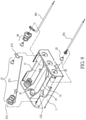
FIG. 7 is a perspective view illustrating the assembly of the battery holder of FIG. 6;
FIG. 8 is a top view illustrating the assembly of the battery holder according to the second embodiment of the present invention;
FIG. 9 is a perspective exploded view illustrating the battery holder according to a third embodiment of the present invention;
FIG. 10 is a perspective view illustrating the assembly of the battery holder of FIG. 9;
FIG. 11 is a top view illustrating the assembly of the battery holder according to the third embodiment of the present invention;
FIG. 12 is a perspective exploded view illustrating the battery holder according to a fourth embodiment of the present invention;
FIG. 13 is a perspective view illustrating the assembly of the battery holder of FIG. 12;
FIG. 14 is a cross sectional view of FIG. 13 taken along an A-A line;
FIG. 15 is a cross sectional view of FIG. 13 taken along a B-B line;
FIG. 16 is a perspective exploded view illustrating the battery holder according to a fifth embodiment of the present invention; and
FIG. 17 is a perspective view illustrating the assembly of the battery holder of FIG. 16.
DETAILED DESCRIPTION OF THE PREFERRED EMBODIMENT
Please refer from FIG. 3 to FIG. 5, a battery holder including a case body 1 and a connection assembly 2 is provided according to a first embodiment of the present invention.
The case body 1 is substantially the same as a conventional case body, and has at least three battery chambers 11 as shown in FIG. 3, the quantity of the at least three battery chambers 11 is an even number equal to or greater than three, for example four battery chambers 11; and a partition plate 12 is disposed between every two of the adjacent battery chambers 11 for partition, the connection assembly 2 is disposed in the at least three battery chambers 11, the connection assembly 2 has at least one anode/cathode connecting unit 21, an anode output terminal 25, a cathode output terminal 26 and an anode/cathode jumping unit 27, thereby allowing the at least three battery chambers 11 to be in a serial connecting status.
The anode output terminal 25 has an anode conduction hook-up wire 251, and the cathode output terminal 26 has a cathode conduction hook-up wire 261, the anode conduction hook-up wire 251 and the cathode conduction hook-up wire 261 are protruded out from a penetrated hole 13 respectively formed in the two adjacently-arranged battery chambers 11, so that the anode conduction hook-up wire 251 and the cathode conduction hook-up wire 261 are adjacently arranged for being conveniently connected to an electronic product to supply DC power to the electronic product.
As show in FIG. 5, a bottom surface defined between two of the at least three battery chambers 11, which are arranged at outer sides, is transversally formed with an accommodation slot 14, two ends of the accommodation slot 14 are respectively formed with a communication slot 141 at locations corresponding to the two battery chambers 11 arranged at the outer sides and allowing an anode contact point 273 of the anode/cathode jumping unit 27 to pass.
As shown in FIG. 3, the anode/cathode jumping unit 27 is formed through a metal wire, for example a steel spring wire, being bent, and the anode/cathode jumping unit 27 has a connection segment 271, one end of the connection segment 271 has a cathode elastic contact point 272 connected to the battery chamber 11 arranged at the outer side, and another end thereof has the anode contact point 273 connected to the other battery chamber 11 arranged at the outer side. The anode contact point 273 has a frame member formed in a geometrical shape, for example a rectangular shape (as shown in FIG. 3, FIG. 6 and FIG. 9) or an annular shape (as shown in FIG. 12 and FIG. 16).
The anode/cathode jumping unit 27 is formed through a metal wire being bent, and provided with a certain rigidity; when being assembled, the anode contact point 273 firstly passes through one of the communication slots 141 formed at one of the battery chambers 11 at arranged at the outer sides then penetrates out from the other communication slot 141 of the other battery chamber 11 arranged at the outer sides, so that the connection segment 271 is able to be accommodated in the accommodation slot 14, and the cathode elastic contact point 272 is riveted in a connection hole 15 of the case body 1, then the anode contact point 273 is riveted in another connection hole 15 of the case body 1, so that the at least one anode/cathode connecting unit 21, the anode output terminal 25, the cathode output terminal 26 and the at least one anode/cathode jumping unit 27 are assembled as the connection assembly 2.
Based on the above-mentioned assembly procedure, the anode/cathode jumping unit 27 is installed from a top end of the case body 1, thus the complicated assembly procedure of the battery holder being reversely disposed and a hole alignment operation being difficult to be processed are overcome, and objectives of saving labor and saving working hours are achieved.
Please refer from FIG. 6 to FIG. 8, which discloses a second embodiment of the battery holder, the same components shared by the second embodiment and the first embodiment are provided with the codes, because there are a lot of the components shared by the second embodiment and the first embodiment, only differences between the two embodiments are illustrated as follows.
A top surface defined between the two battery chambers 11 arranged at the outer sides of the case body 1 is transversally formed with an accommodation slot 14 allowing the anode/cathode jumping unit 27 to be installed; as such, the two communication slots 141 disclosed in the first embodiment are not required in the second embodiment. Advantages achieved by this embodiment are that the accommodation slot 14 is formed inside the case body 1, so that dangers caused by a short circuit status on a bottom surface of the case body 1 can be prevented.
Moreover, the partition plate 12 arranged between every two adjacent battery chambers 11 is perpendicular to the accommodation slot 14, and a position corresponding to an anode protrusion (known as prior art therefore not shown in figures) of a battery located between every two adjacent partition plates 12 and above the case body 1 is vertically extended with a pair of abutting sheets 121 allowing the anode protrusion to pass therebetween, so that the anode protrusion is able to be in contact with the anode contact point 273 or the anode/cathode connecting unit 21.
Please refer from FIG. 9 to FIG. 11, which discloses a third embodiment of the battery holder, the same components shared by the third embodiment and the first embodiment are provided with the codes, because there are a lot of the components shared by the third embodiment and the first embodiment, only differences between the two embodiments are illustrated as follows.
The quantity of the at least three battery chambers 11 is an odd number equal to or greater than three, for example three battery chambers 11, a top surface defined between the two battery chambers 11 arranged at the outer sides of the case body 1 is diagonally formed with an accommodation slot 14 allowing the anode/cathode jumping unit 27 to be installed. Advantage of this embodiment is that the accommodation slot 14 is formed inside the case body 1, so that dangers caused by a short circuit status on a bottom surface of the case body 1 can be prevented.
Moreover, the partition plate 12 is arranged between every two of the adjacent battery chambers 11 in the case body 1, the partition plate 12 is longitudinally formed with a crossed slot 122, in an opened status, at a path where the accommodation slot 14 passes, so that the connection segment 271 is able to longitudinally pass each of the crossed slots 122 so as to be accommodated in the accommodation slot 14.
Please refer to FIG. 12 to FIG. 15, which discloses a fourth embodiment of the battery holder, the same components shared by the fourth embodiment and the second embodiment are provided with the codes, because there are a lot of the components shared by the fourth embodiment and the second embodiment, only differences between the two embodiments are illustrated as follows.
As shown in FIG. 12, FIG. 14 and FIG. 15, the accommodation slot 14 is transversally formed on a top surface defined between two of the at least three battery chambers 11 which are arranged at the outer sides, a plate slot 123 allowing the anode contact point 273 of the anode/cathode jumping unit 27 to pass is respectively formed at a location defined between the two battery chambers 11 arranged at the outer sides and at a location defined at the partition plates 12 arranged at a same side with respect to the accommodation slot 14.
Moreover, a hanging segment 124, which can be communicated with each other, is integrally disposed at a location defined between the partition plate 12 disposed corresponding to the at least one anode/cathode connecting unit 21 and the case body 1, thereby allowing each of the anode/cathode connecting units 21 to be in a hanging status, so that a riveting operation can be assisted. What shall be addressed is the hanging segment 124 is not limited to be applied in this embodiment; besides the second embodiment, the hanging segment 124 can also be applied in the first embodiment, the third embodiment and a fifth embodiment.
When being assembled, the anode contact point 273 firstly passes through the plate slot 123 of each of the partition plates 12 between the two battery chambers 11 arranged at the outer sides, so that the connection segment 271 is able to be accommodated in the accommodation slot 14, and the cathode elastic contact point 272 is riveted in the connection hole 15 of the case body 1, then the anode contact point 273 is riveted in the another connection hole 15 of the case body 1, so that the at least one anode/cathode connecting unit 21, the anode output terminal 25, the cathode output terminal 26 and the anode/cathode jumping unit 27 are assembled as the connection assembly 2.
Please refer to FIG. 16 and FIG. 17, which discloses a fifth embodiment of the battery holder, the same components shared by the fifth embodiment and the third embodiment are provided with the codes, because there are a lot of the components shared by the fifth embodiment and the third embodiment, only differences between the two embodiments are illustrated as follows.
The partition plate 12 is provided between every two of the adjacent battery chambers 11 in the case body 1 for partition, the partition plate 12 is longitudinally formed with a penetrated slot 125, in a closed status, at a path where the accommodation slot 14 passes, so that the connection segment 271 is able to transversally pass each of the penetrated slots 125 so as to be accommodated in the accommodation slot 14.
Advantages achieved by the second embodiment, the third embodiment, the fourth embodiment and the fifth embodiment are that the accommodation slot 14 is formed inside the case body 1, so that dangers caused by a short circuit status due to the anode/cathode jumping unit 27 being exposed can be prevented.
Based on what has been disclosed above, advantages achieved by the present invention are as follows: the anode/cathode jumping unit formed through a metal wire, for example a steel spring wire, being bent is utilized for replacing the conventional assembly of the anode contact point, the cathode contact point and the flexible hook-up wire, and the anode/cathode jumping unit is installed from the top end of the case body, thus the complicated assembly procedure of the battery holder being reversely disposed and a hole alignment operation being difficult to be processed are overcome. Accordingly, the battery holder capable of simplifying assembly procedure provided by the present invention is novel and more practical in use comparing to prior art.
Many modifications and other embodiments of the inventions set forth herein will come to mind to one skilled in the art to which these inventions pertain having the benefit of the teachings presented in the foregoing descriptions and the associated drawings. Therefore, it is to be understood that the inventions are not to be limited to the specific examples of the embodiments disclosed and that modifications and other embodiments are intended to be included within the scope of the appended claims. Although specific terms are employed herein, they are used in a generic and descriptive sense only and not for purposes of limitation.

Claims (10)

What is claimed is:
1. A battery holder capable of simplifying assembly procedure, including:
a case body, having at least three battery chambers, and
a connection assembly, having at least one anode/cathode connecting unit, an anode output terminal, a cathode output terminal and an anode/cathode jumping unit, thereby allowing said at least three battery chambers to be in a serial connecting status;
wherein said battery holder is characterized in that: an accommodation slot is formed between two battery chambers of said at least three battery chambers which are arranged at outer sides, said anode/cathode jumping unit is formed through a metal wire being bent, and has a connection segment accommodated in said accommodation slot, one end of said connection segment has a cathode elastic contact point connected to a first battery chamber of said two battery chambers arranged at said outer side, and another end thereof has an anode contact point connected to a second battery chamber of said two battery chambers arranged at said outer side.
2. The battery holder capable of simplifying assembly procedure as claimed in claim 1, wherein said accommodation slot is transversally disposed on a bottom surface defined between said two battery chambers arranged at said outer sides, and two ends of said accommodation slot are respectively formed with a communication slot at locations corresponding to said two battery chambers arranged at said outer sides and allowing said anode contact point to pass.
3. The battery holder capable of simplifying assembly procedure as claimed in claim 1, wherein said accommodation slot is transversally disposed on a top surface defined between said two battery chambers arranged at said outer sides; wherein a partition plate is provided between every two adjacent battery chambers of said at least three battery chambers for partition, wherein said partition plate is perpendicular to said accommodation slot, and a position corresponding to an anode protrusion of a battery located between every two adjacent said partition plates and above said case is vertically extended with a pair of abutting sheets allowing said anode protrusion to pass therebetween.
4. The battery holder capable of simplifying assembly procedure as claimed in claim 1, wherein said accommodation slot is transversally disposed on a top surface defined between said two battery chambers arranged at said outer sides; wherein a partition plate is provided between every two adjacent battery chambers of said at least three battery chambers for partition, a plate slot is respectively formed at a location defined between said two battery chambers arranged at said outer sides and at a location defined at said partition plate arranged at a same side with respect to said accommodation slot, and each of said plate slots allows said anode contact point to transversally pass.
5. The battery holder capable of simplifying assembly procedure as claimed in claim 1, wherein said accommodation slot is diagonally disposed on a top surface defined between said two battery chambers arranged at said outer sides; wherein a partition plate is provided between every two adjacent battery chambers of said at least three battery chambers for partition, each of said partition plates is longitudinally formed with a crossed slot, in a opened status, at a path where said accommodation slot passes, so that said connection segment is able to longitudinally pass each of said crossed slots so as to be accommodated in said accommodation slot.
6. The battery holder capable of simplifying assembly procedure as claimed in claim 1, wherein said accommodation slot is diagonally disposed on a top surface defined between said two battery chambers arranged at said outer sides; wherein a partition plate is provided between every two adjacent battery chambers of said at least three battery chambers for partition, each of said partition plates is longitudinally formed with a penetrated slot, in a closed status, at a path where said accommodation slot passes, so that said connection segment is able to transversally pass each of said penetrated slots so as to be accommodated in said accommodation slot.
7. The battery holder capable of simplifying assembly procedure as claimed in claim 1, wherein said metal wire is a steel spring wire; and said anode contact point has a frame member formed in a geometrical shape.
8. The battery holder capable of simplifying assembly procedure as claimed in claim 7, wherein said frame member is formed in a rectangular shape or in an annular shape.
9. The battery holder capable of simplifying assembly procedure as claimed in claim 1, wherein a partition plate is provided between every two adjacent battery chambers of said at least three battery chambers for partition, and a hanging segment, which is able to be communicated with each other, is integrally disposed at a location defined between said partition plates disposed corresponding to each of said anode/cathode connecting units and said case body, thereby allowing each of said anode/cathode connecting units to be in a hanging status.
10. The battery holder capable of simplifying assembly procedure as claimed in claim 1, wherein said anode output terminal has an anode conduction hook-up wire, and said cathode output terminal has a cathode conduction hook-up wire; said anode conduction hook-up wire and said cathode conduction hook-up wire are protruded out from a penetrated hole respectively formed in said two adjacent battery chambers, so that said anode conduction hook-up wire and said cathode conduction hook-up wire are adjacently arranged.
US16/432,856 2018-10-24 2019-06-05 Battery holder capable of simplifying assembly procedure Active 2040-08-04 US11233290B2 (en)

Applications Claiming Priority (4)

Application Number Priority Date Filing Date Title
TW107214462U TWM573901U (en) 2018-10-24 2018-10-24 Battery box capable of simplifying assembly process
TW107214462 2018-10-24
TW108206024 2019-05-14
TW108206024U TWM584988U (en) 2019-05-14 2019-05-14 Battery box capable of saving assembly process

Publications (2)

Publication Number Publication Date
US20200136103A1 US20200136103A1 (en) 2020-04-30
US11233290B2 true US11233290B2 (en) 2022-01-25

Family

ID=70328451

Family Applications (1)

Application Number Title Priority Date Filing Date
US16/432,856 Active 2040-08-04 US11233290B2 (en) 2018-10-24 2019-06-05 Battery holder capable of simplifying assembly procedure

Country Status (2)

Country Link
US (1) US11233290B2 (en)
SG (1) SG10201908698VA (en)

Citations (3)

* Cited by examiner, † Cited by third party
Publication number Priority date Publication date Assignee Title
US4161568A (en) * 1978-01-11 1979-07-17 Schonstedt Instrument Company Battery holder
US4514477A (en) * 1982-09-25 1985-04-30 Shinsei Kogyo Co., Ltd. Cassette-type power unit for a motor toy
US6326766B1 (en) * 2000-06-09 2001-12-04 Shoot The Moon Products Ii, Llc Rechargable battery pack and battery pack charger with safety mechanisms

Patent Citations (3)

* Cited by examiner, † Cited by third party
Publication number Priority date Publication date Assignee Title
US4161568A (en) * 1978-01-11 1979-07-17 Schonstedt Instrument Company Battery holder
US4514477A (en) * 1982-09-25 1985-04-30 Shinsei Kogyo Co., Ltd. Cassette-type power unit for a motor toy
US6326766B1 (en) * 2000-06-09 2001-12-04 Shoot The Moon Products Ii, Llc Rechargable battery pack and battery pack charger with safety mechanisms

Also Published As

Publication number Publication date
US20200136103A1 (en) 2020-04-30
SG10201908698VA (en) 2020-05-28

Similar Documents

Publication Publication Date Title
US10135101B2 (en) Power storage module
JP6246483B2 (en) Battery pack for electric tools
US11088388B2 (en) Clamping member and battery module using the same
US7843165B2 (en) Charging apparatus
CN108701784B (en) Battery pack
US4083011A (en) Battery holder and connector for a radio receiver or the like
US11233290B2 (en) Battery holder capable of simplifying assembly procedure
US7367821B2 (en) Power distribution system and a method for assembling the power distribution system
US8142924B2 (en) Battery cover mechanism
US11420043B2 (en) Low-frequency treatment device, body for low-frequency treatment device, and combination of pad and holder for low-frequency treatment device
US10381613B2 (en) Detachable battery rack
US20160104982A1 (en) Connecting device for electronic appliance
AU2018202180B2 (en) Master battery, slave battery, and battery kit
US9466906B2 (en) Resilient contact terminal and connector using same
US20150357611A1 (en) Battery case and electrode plate set for use in the same
CN214542421U (en) Mounting seat, battery pack main body and battery pack
WO2015129148A1 (en) Wiring tool
JP6701352B2 (en) Card holder device and mobile device for mounting telephone card
CN218679662U (en) Cabinet combination support
US20160104980A1 (en) Connecting apparatus for electronic appliance
CN109407788B (en) Casing (CN)
EP0493253B1 (en) Socket for batteries
EP4044409A1 (en) Motor brush, motor and washing machine
US20230182006A1 (en) Gaming machine
CN213071617U (en) Small-sized track power taking device

Legal Events

Date Code Title Description
FEPP Fee payment procedure

Free format text: ENTITY STATUS SET TO UNDISCOUNTED (ORIGINAL EVENT CODE: BIG.); ENTITY STATUS OF PATENT OWNER: SMALL ENTITY

FEPP Fee payment procedure

Free format text: ENTITY STATUS SET TO SMALL (ORIGINAL EVENT CODE: SMAL); ENTITY STATUS OF PATENT OWNER: SMALL ENTITY

STPP Information on status: patent application and granting procedure in general

Free format text: NON FINAL ACTION MAILED

STPP Information on status: patent application and granting procedure in general

Free format text: RESPONSE TO NON-FINAL OFFICE ACTION ENTERED AND FORWARDED TO EXAMINER

STPP Information on status: patent application and granting procedure in general

Free format text: NOTICE OF ALLOWANCE MAILED -- APPLICATION RECEIVED IN OFFICE OF PUBLICATIONS

STPP Information on status: patent application and granting procedure in general

Free format text: PUBLICATIONS -- ISSUE FEE PAYMENT VERIFIED

STCF Information on status: patent grant

Free format text: PATENTED CASE