US11231202B2 - Fabric drop-down diffusers - Google Patents
Fabric drop-down diffusers Download PDFInfo
- Publication number
- US11231202B2 US11231202B2 US15/417,006 US201715417006A US11231202B2 US 11231202 B2 US11231202 B2 US 11231202B2 US 201715417006 A US201715417006 A US 201715417006A US 11231202 B2 US11231202 B2 US 11231202B2
- Authority
- US
- United States
- Prior art keywords
- panel
- hoop
- drop
- diffuser
- upper panel
- Prior art date
- Legal status (The legal status is an assumption and is not a legal conclusion. Google has not performed a legal analysis and makes no representation as to the accuracy of the status listed.)
- Active, expires
Links
Images


Classifications
-
- F—MECHANICAL ENGINEERING; LIGHTING; HEATING; WEAPONS; BLASTING
- F24—HEATING; RANGES; VENTILATING
- F24F—AIR-CONDITIONING; AIR-HUMIDIFICATION; VENTILATION; USE OF AIR CURRENTS FOR SCREENING
- F24F13/00—Details common to, or for air-conditioning, air-humidification, ventilation or use of air currents for screening
- F24F13/02—Ducting arrangements
- F24F13/06—Outlets for directing or distributing air into rooms or spaces, e.g. ceiling air diffuser
- F24F13/062—Outlets for directing or distributing air into rooms or spaces, e.g. ceiling air diffuser having one or more bowls or cones diverging in the flow direction
-
- G—PHYSICS
- G03—PHOTOGRAPHY; CINEMATOGRAPHY; ANALOGOUS TECHNIQUES USING WAVES OTHER THAN OPTICAL WAVES; ELECTROGRAPHY; HOLOGRAPHY
- G03B—APPARATUS OR ARRANGEMENTS FOR TAKING PHOTOGRAPHS OR FOR PROJECTING OR VIEWING THEM; APPARATUS OR ARRANGEMENTS EMPLOYING ANALOGOUS TECHNIQUES USING WAVES OTHER THAN OPTICAL WAVES; ACCESSORIES THEREFOR
- G03B21/00—Projectors or projection-type viewers; Accessories therefor
- G03B21/14—Details
- G03B21/145—Housing details, e.g. position adjustments thereof
-
- G—PHYSICS
- G03—PHOTOGRAPHY; CINEMATOGRAPHY; ANALOGOUS TECHNIQUES USING WAVES OTHER THAN OPTICAL WAVES; ELECTROGRAPHY; HOLOGRAPHY
- G03B—APPARATUS OR ARRANGEMENTS FOR TAKING PHOTOGRAPHS OR FOR PROJECTING OR VIEWING THEM; APPARATUS OR ARRANGEMENTS EMPLOYING ANALOGOUS TECHNIQUES USING WAVES OTHER THAN OPTICAL WAVES; ACCESSORIES THEREFOR
- G03B21/00—Projectors or projection-type viewers; Accessories therefor
- G03B21/14—Details
- G03B21/16—Cooling; Preventing overheating
-
- G—PHYSICS
- G03—PHOTOGRAPHY; CINEMATOGRAPHY; ANALOGOUS TECHNIQUES USING WAVES OTHER THAN OPTICAL WAVES; ELECTROGRAPHY; HOLOGRAPHY
- G03B—APPARATUS OR ARRANGEMENTS FOR TAKING PHOTOGRAPHS OR FOR PROJECTING OR VIEWING THEM; APPARATUS OR ARRANGEMENTS EMPLOYING ANALOGOUS TECHNIQUES USING WAVES OTHER THAN OPTICAL WAVES; ACCESSORIES THEREFOR
- G03B21/00—Projectors or projection-type viewers; Accessories therefor
- G03B21/54—Accessories
-
- G—PHYSICS
- G03—PHOTOGRAPHY; CINEMATOGRAPHY; ANALOGOUS TECHNIQUES USING WAVES OTHER THAN OPTICAL WAVES; ELECTROGRAPHY; HOLOGRAPHY
- G03B—APPARATUS OR ARRANGEMENTS FOR TAKING PHOTOGRAPHS OR FOR PROJECTING OR VIEWING THEM; APPARATUS OR ARRANGEMENTS EMPLOYING ANALOGOUS TECHNIQUES USING WAVES OTHER THAN OPTICAL WAVES; ACCESSORIES THEREFOR
- G03B29/00—Combinations of cameras, projectors or photographic printing apparatus with non-photographic non-optical apparatus, e.g. clocks or weapons; Cameras having the shape of other objects
-
- G—PHYSICS
- G03—PHOTOGRAPHY; CINEMATOGRAPHY; ANALOGOUS TECHNIQUES USING WAVES OTHER THAN OPTICAL WAVES; ELECTROGRAPHY; HOLOGRAPHY
- G03B—APPARATUS OR ARRANGEMENTS FOR TAKING PHOTOGRAPHS OR FOR PROJECTING OR VIEWING THEM; APPARATUS OR ARRANGEMENTS EMPLOYING ANALOGOUS TECHNIQUES USING WAVES OTHER THAN OPTICAL WAVES; ACCESSORIES THEREFOR
- G03B31/00—Associated working of cameras or projectors with sound-recording or sound-reproducing means
-
- F—MECHANICAL ENGINEERING; LIGHTING; HEATING; WEAPONS; BLASTING
- F24—HEATING; RANGES; VENTILATING
- F24F—AIR-CONDITIONING; AIR-HUMIDIFICATION; VENTILATION; USE OF AIR CURRENTS FOR SCREENING
- F24F13/00—Details common to, or for air-conditioning, air-humidification, ventilation or use of air currents for screening
- F24F13/02—Ducting arrangements
- F24F13/0218—Flexible soft ducts, e.g. ducts made of permeable textiles
-
- F—MECHANICAL ENGINEERING; LIGHTING; HEATING; WEAPONS; BLASTING
- F24—HEATING; RANGES; VENTILATING
- F24F—AIR-CONDITIONING; AIR-HUMIDIFICATION; VENTILATION; USE OF AIR CURRENTS FOR SCREENING
- F24F13/00—Details common to, or for air-conditioning, air-humidification, ventilation or use of air currents for screening
- F24F13/02—Ducting arrangements
- F24F13/06—Outlets for directing or distributing air into rooms or spaces, e.g. ceiling air diffuser
- F24F2013/0608—Perforated ducts
-
- F—MECHANICAL ENGINEERING; LIGHTING; HEATING; WEAPONS; BLASTING
- F24—HEATING; RANGES; VENTILATING
- F24F—AIR-CONDITIONING; AIR-HUMIDIFICATION; VENTILATION; USE OF AIR CURRENTS FOR SCREENING
- F24F2221/00—Details or features not otherwise provided for
- F24F2221/14—Details or features not otherwise provided for mounted on the ceiling
-
- Y—GENERAL TAGGING OF NEW TECHNOLOGICAL DEVELOPMENTS; GENERAL TAGGING OF CROSS-SECTIONAL TECHNOLOGIES SPANNING OVER SEVERAL SECTIONS OF THE IPC; TECHNICAL SUBJECTS COVERED BY FORMER USPC CROSS-REFERENCE ART COLLECTIONS [XRACs] AND DIGESTS
- Y02—TECHNOLOGIES OR APPLICATIONS FOR MITIGATION OR ADAPTATION AGAINST CLIMATE CHANGE
- Y02W—CLIMATE CHANGE MITIGATION TECHNOLOGIES RELATED TO WASTEWATER TREATMENT OR WASTE MANAGEMENT
- Y02W10/00—Technologies for wastewater treatment
- Y02W10/10—Biological treatment of water, waste water, or sewage
Definitions
- HVAC systems heating ventilating and air-conditioning systems
- fabric drop-down diffusers
- HVAC systems heating ventilating and air-conditioning systems typically include a blower that circulates conditioned air through one or more areas in a building. As used herein, the air entering the areas is referred to as, “supply air,” and the leaving air is called, “return air.” Some HVAC systems will heat, cool, dehumidify, humidify, filter and/or otherwise condition the air before one or more discharge outlets deliver the supply air to chosen areas of the building.
- a drop-down diffuser is one example of such a discharge outlet.
- a drop-down diffuser usually comprises a rigid box-like structure mounted at an overhead location, usually near the ceiling of the building.
- a supply air duct typically feeds supply air down in through the top of the box-like structure, and peripheral openings in the diffuser release the supply air to the surrounding area.
- Some drop-down diffusers have a sheet of porous fabric attached to the rigid box-like structure.
- the porous fabric helps in evenly dispersing the supply air into the areas being served by the HVAC system.
- One example of such a diffuser is disclosed in US Published Patent Application No. 2008/0176506 A1, which is specifically incorporated herein by reference in its entirety.
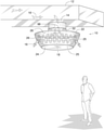
- FIG. 1 is a perspective view of an example drop-down diffuser constructed in accordance with the teachings disclosed herein.
- FIG. 2 is a top view of the example diffuser shown in FIG. 1 .
- FIG. 3 is a front view of the example diffuser shown in FIG. 1 , wherein a portion of the outer fabric is cut away to show the example diffuser's internal air chamber and one or more example hoops.
- FIG. 4 is a front view similar to FIG. 3 but showing the addition of an example zipper and one or more example drawstrings.
- FIG. 5 is a top view of an example upper hoop constructed in accordance with the teachings disclosed herein.
- FIG. 6 is a top view of an example upper hoop, an example central hoop and example spokes constructed in accordance with the teachings disclosed herein.
- FIG. 7 is a top view of an example upper hoop, an example central hub and example spokes constructed in accordance with the teachings disclosed herein.
- FIG. 8 is a top view of an example upper hoop, an example central hoop, example spokes and an example hub constructed in accordance with the teachings disclosed herein.
- FIG. 9 is a top view of an example lower hoop constructed in accordance with the teachings disclosed herein.
- FIG. 10 is a top view of an example lower hoop, an example hub and example spokes constructed in accordance with the teachings disclosed herein.
- FIG. 11 is a top view of another example lower hoop, an example hub and example spokes constructed in accordance with the teachings disclosed herein.
- FIG. 12 is a top view similar to FIG. 2 but showing an example diffuser with a plurality of baffles, wherein the example diffuser is constructed in accordance with the teachings disclosed herein.
- FIG. 13 is a front view of the example diffuser shown in FIG. 12 , wherein a portion of the outer fabric is cut away to show the example diffuser's internal baffles.
- FIG. 14 is a front view similar to FIG. 13 but showing the example baffles having a plurality of openings.
- FIG. 15 is a front view similar to FIG. 3 but showing the example diffuser having an example internal screen.
- FIG. 16 is a front view similar to FIGS. 3 and 4 but showing an example diffuser with a vertically elongate tension member, wherein the example diffuser is constructed in accordance with the teachings disclosed herein.
- FIG. 17 is a front view similar to FIG. 16 but showing the example diffuser in another configuration.
- FIG. 18 is a front view similar to FIG. 4 but showing another example diffuser constructed in accordance with the teachings disclosed herein, wherein the example diffuser has a lower drawstring.
- FIG. 19 is a front view similar to FIG. 18 but showing the example drawstring tighter.
- FIG. 20 is a front view similar to FIG. 4 but showing another example diffuser constructed in accordance with the teachings disclosed herein, wherein the example diffuser has a diagonal drawstring.
- FIG. 21 is a front view similar to FIG. 20 but showing the example drawstring tighter.
- FIG. 22 is a front view similar to FIG. 4 but showing another example diffuser constructed in accordance with the teachings disclosed herein, wherein the example diffuser has a vertically elongate compression member that holds the example diffuser in a skewed configuration.
- FIG. 23 is a front view similar to FIG. 4 but showing another example diffuser constructed in accordance with the teachings disclosed herein, wherein the example diffuser has a vertical elongate tension member that forces the example diffuser's lower panel into the shape of a curved cone.
- FIG. 24 is a front view similar to FIG. 23 but showing the example vertically elongate tension member tighter.
- FIG. 25 is a front view similar to FIG. 4 but showing another example diffuser constructed in accordance with the teachings disclosed herein, wherein the example diffuser has a vertical elongate compression member that forces the example diffuser's lower panel into the shape of a curved cone.
- FIG. 26 is an enlarged view of an example joint within an encircled area of FIG. 3 .
- FIG. 27 is a view similar to FIG. 26 but showing an alternate example joint constructed in accordance with the teachings disclosed herein.
- FIG. 28 is a view similar to FIGS. 26 and 27 but showing another alternate example joint constructed in accordance with the teachings disclosed herein.
- FIG. 29 is a front view similar to FIG. 3 but showing another example diffuser constructed in accordance with the teaching disclosed herein, wherein portions of the outer fabric and an example inner baffle are cut away to show internal features of the example diffuser.
- FIG. 30 is a front view similar to FIG. 29 but showing the example diffuser in another configuration.
- FIG. 31 is a front view similar to FIG. 29 but showing another example diffuser constructed in accordance with the teachings disclosed herein.
- FIG. 32 is a front view similar to FIG. 31 but showing the example diffuser in another configuration.
- FIG. 33 is a front view similar to FIGS. 29 and 31 but showing another example diffuser constructed in accordance with the teachings disclosed herein.
- FIG. 34 is a front view similar to FIG. 33 but showing the example diffuser in another configuration.
- FIG. 35 is a front view similar to FIGS. 29, 31 and 33 but showing another example diffuser constructed in accordance with the teachings disclosed herein.
- FIG. 36 is a front view similar to FIG. 35 but showing the example diffuser in another configuration.
- Example drop-down diffusers for HVAC systems are comprised of non-porous and/or air-permeable fabric supported internally by one or more rigid hoops.
- a drawstring tightens fabric panels over an upper and/or a lower hoop.
- internal fabric baffles help direct airflow and muffle noise.
- Some example diffusers have various means for connecting to a sheet metal duct and various means for creating an internal conical air deflector.
- the conical deflector is curved and its shape is adjustable.
- FIGS. 1-3 show various views of an example drop-down diffuser 10 mounted to an overhead supply air duct 12 .
- the supply air duct 12 is made of sheet metal and is in a generally rectangular shape.
- a cylindrical branch duct 14 also made of sheet metal, connects the supply air duct 12 to the diffuser 10 .
- the ducts 12 , 14 are of other shapes and made of materials other than sheet metal.
- a blower or some other air-moving means forces air 16 in series flow through the supply air duct 12 , down through the branch duct 14 , through a supply air inlet 18 of the diffuser 10 , and into an air chamber 20 of the diffuser 10 . From the air chamber 20 , the diffuser 10 disperses the air 16 into a room, area or other space surrounding the diffuser 10 .
- the diffuser 10 is of a design that is lightweight, muffles airflow noise, muffles blower and/or other mechanical noises, evenly and/or strategically disperses air, reduces (e.g., minimizes) condensation on the surface of the diffuser, is machine washable, and is collapsible for compact packaging and shipping.
- the diffuser 10 comprises an upper panel 22 , a lower panel 24 , a circumferential fabric sheet 26 , an upper hoop 28 , a lower hoop 30 , and a sleeve 32 connecting the upper panel 22 to the branch duct 14 .
- a central hoop 34 reinforces the area where the sleeve 32 connects to the upper panel 22 .
- the upper panel 22 defines the supply air inlet 18
- the panels 22 , 24 and the sheet 26 define the air chamber 20 .
- the lower hoop 30 is smaller than the upper hoop 28 .
- the circumferential fabric sheet 26 is positioned at an angle to at least partially face downward, thereby facilitating the distribution of the air 16 into the space around and beneath the diffuser 10 .
- each of the upper panel 22 , the lower panel 24 , the sheet 26 and the sleeve 32 are made of a pliable fabric (e.g., polyester fabric, screen mesh, netting, etc.).
- a pliable fabric e.g., polyester fabric, screen mesh, netting, etc.
- one or more areas of the fabric is air permeable either by a porous quality of the fabric itself and/or by a number of openings 25 cut into the fabric.
- entire sections of the diffuser 10 are completely impervious to air.
- the sleeve 32 , the upper panel 22 , and the lower panel 24 are impervious to air, while only the circumferential fabric sheet 26 is air permeable via the openings 25 and/or via porosity of the fabric itself.
- Examples of the diffuser 10 include all permeable/impermeable combinations of the upper panel 22 , the lower panel 24 , the sheet 26 and the sleeve 32 .
- some examples of the diffuser 10 include the upper hoop 28 , the lower hoop 30 and/or the central hoop 34 .
- the hoops 28 , 30 , 34 are relatively stiff compared to the fabric of the diffuser 10 .
- Example hoop materials include metal, fiberglass, plastic, etc.
- the upper hoop 28 holds an upper fabric sheet 36 of the upper panel 22 in radial tension, thus keeping the upper fabric sheet 36 generally taut.
- some examples of the diffuser 10 include an upper drawstring 38 , as shown in FIG. 4 .
- the drawstring 38 extends through an upper loop of material 40 that runs circumferentially along a periphery of the upper panel 22 that is wrapped over the upper hoop 28 .
- the upper loop material 40 corresponds to a series of spaced apart loops distributed circumferentially along the periphery of the upper panel 22 . Manually cinching the upper drawstring 38 exerts a constricting force that radially tightens the upper fabric sheet 36 .
- the upper panel 22 includes one or more hooks attached thereto that extend circumferentially along the periphery of the upper panel 22 (e.g., extruded plastic hook(s) to latch on to the upper hoop 28 .
- cinching the drawstring 38 urges the hook(s) against the upper hoop 28 and exerts a radial tensile force across the upper panel 22 to keep the panel 22 taut.
- the lower hoop 30 holds the lower panel 24 in radial tension.
- some examples of diffuser 10 include a lower drawstring 42 , as shown in FIG. 4 .
- the lower drawstring 42 extends in a loop of material 44 that runs circumferentially along a periphery of the lower panel 24 that is wrapped over the lower hoop 30 .
- the lower drawstring 42 runs through a series of spaced apart loops distributed circumferentially along the periphery of the lower panel 22 . Manually cinching the lower drawstring 42 exerts a constricting force that radially tightens the lower panel 24 .
- the upper panel 22 , the lower panel 24 , and the circumferential fabric sheet 26 may be interconnected in any suitable manner such as, for example, via zippers, hook and loop fasteners, sewing, etc.
- a zipper 46 (or comparable joint) provides means for manually accessing the drawstrings 38 , 42 .
- the zipper 46 is shown lying between and generally parallel to the hoops 28 , 30 , other examples of the diffuser 10 have the zipper 46 at any orientation and location on the diffuser 10 .
- Example zipper locations include adjacent to the lower hoop 30 , adjacent to the upper hoop 28 , on the circumferential fabric sheet 26 , on the upper panel 22 , and on the lower panel 24 .
- the openings 25 are shown in the illustrated example as being above the zipper 46 . in some examples, the openings 25 may be below the zipper 46 . In other examples, there may be openings 25 both above and below the location of the zipper 46 .
- the lower hoop 30 is suspended from the circumferential fabric sheet 26 , which, in turn, is suspended from the upper hoop 28 . That is, in some examples, the weight of the lower hoop 30 and/or the circumferential fabric sheet 26 is substantially supported by the upper hoop 28 . In some examples, the weight of the lower hoop 28 keeps the circumferential fabric sheet 26 taut in a direction extending between the lower hoop 30 and the upper hoop 28 .
- the hoops 28 , 30 , 34 can be of any imaginable shape and size.
- Some example hoop shapes include circular, rectangular, polygonal, and the shapes shown FIGS. 5-11 .
- the illustrated example of FIG. 5 shows the upper hoop 28 as circular.
- FIG. 6 is an example hoop 48 comprising a plurality of spokes 50 connecting upper the hoop 28 to the central hoop 34 .
- the illustrated example of FIG. 7 shows a plurality of spokes 52 extending radially between the upper hoop 28 and a hub 54 .
- the hub 54 can be used for connecting to a vertically elongate compression member 56 (e.g., FIG.
- the compression and tension members 56 , 60 may be attached to a portion of one or more of the hoops 28 , 30 , 34 and/or one or more of the spokes 50 .
- the vertically elongate compression member 56 include a rod, a shaft, a tube, a bar and/or any other member capable of carrying and transmitting compressive forces along its length. In some examples, the compressive forces arise due to vertical tension in the circumferential fabric sheet 26 .
- the compression member 56 provides additional force beyond the weight of the lower hoop 30 to maintain the circumferential fabric sheet 26 taut between the upper and lower hoops 28 , 30 .
- the vertically elongate tension member 60 include a cord, a rope, a chain, a wire, a cable, a strap, and/or any other member capable of carrying and transmitting tensile forces along its length.
- the illustrated example of FIG. 8 shows a plurality of spokes 62 connecting the hub 54 and the central hoop 34 to the upper hoop 28 .
- the hoops 28 , 30 , 34 may include more than one hub to serve as different points of attachment for more than one compression member 56 and/or tension member 60 .
- the compression member 56 and the tension member 60 are shown and described in the illustrated examples as being vertically elongate, in some examples, the compression member 56 and/or the tension member 60 may be elongate in a non-vertical direction.
- the compression member 56 and/or the tension member 60 may connect to the hoops 28 , 30 , 34 , the spokes 50 , and/or the hub 54 at an angle relative to the vertical direction.
- FIG. 9 shows the lower hoop 30 as circular.
- the illustrated example of FIG. 10 shows a plurality of spokes 64 extending radially between the lower hoop 30 and a hub 66 .
- the elongate compression member 56 connects the hub 66 of FIG. 10 to the hub 54 of FIG. 8 .
- the illustrated example of FIG. 11 shows an asymmetrical set of spokes 68 extending radially between the lower hoop 30 and the hub 66 to place the hub 66 at a radially offset position relative to the hoop 30 .
- the hub's radially offset position in combination with the elongate compression member 56 connected to a radially centered hub 54 in the upper hoop 28 creates a skewed diffuser 10 a , as shown in FIG. 22 .
- the diffuser 10 a of FIG. 22 is skewed in that the lower hoop 30 is not aligned or centered with the upper hoop 28 .
- the misalignment of the upper and lower hoops 28 , 30 results in the circumferential fabric sheet 26 having different angles (relative to a vertical direction) at different points around the diffuser 10 .
- at least one portion of the circumferential fabric sheet 26 is substantially vertical (e.g., the right-hand side of the diffuser 10 a as illustrated in FIG.
- the changes in the angle of the fabric sheet 26 also affect the shape or corresponding area of the sheet 26 facing away from the diffuser 10 a in each direction.
- the changes in the shape, angle, and/or area of the circumferential sheet 26 may be used to control the direction and volume of the air 16 that is dispersed in each direction out of the diffuser 10 .
- the diffuser 10 b includes a plurality of baffles 70 (e.g., five baffles).
- the baffles 70 help direct the air 16 through the diffuser 10 b , and the baffles 70 can be of any quantity.
- Example baffle materials include fabric, metal, plastic, air permeable sheeting, and impermeable sheeting.
- the baffles 70 also help in muffling noise.
- the baffles 70 extend up into the sleeve 32 for greater flow control and/or additional noise muffling.
- FIG. 14 shows the diffuser 10 c , which is the same as the diffuser 10 b of FIGS. 12 and 13 but with the addition of discrete air passage slits 72 in a lower profile baffle 70 ′.
- the baffles 70 ′ being of a lower profile, do not extend up into the sleeve 32 , thereby resulting in changes to the airflow characteristics through the diffuser 10 c , which can be desirable in certain applications.
- the slits 72 (or comparable openings) also alter the airflow pattern.
- the slits 72 shown in FIG. 14 may be implemented in conjunction with the higher profile baffles 70 shown in FIGS. 12 and 13 .
- the number and/or size of the slits 72 (or other openings) within the baffles 70 may differ on different ones of the baffles 70 . In this manner, differences in airflow leaving the diffuser 10 c at different points around its circumference may be established without changing an exterior appearance of the diffuser 10 c . As a specific example, increases the quantity and/or size of slits within one side of the diffuser 10 c would increase the airflow out that side of the diffuser 10 c . Such an arrangement may be useful when the diffuser 10 c is installed close to an exterior wall where it may be desirable to have greater airflow as compared to an interior region of the conditioned space surrounding the diffuser.
- FIGS. 16 and 17 show the diffuser 10 e with a suspension cord used as the elongate tension member 60 .
- an upper end of the tension member 60 connects to the upper hub 54 ( FIGS. 7 and 8 ), and a lower end of the tension member 60 connects to the lower hub 66 ( FIG. 10 ).
- at least one of the tension member 60 connects to the spokes and/or the associated upper and lower hoops 28 , 30 .
- both ends of the tension member 60 connect to the either the upper hoop 28 (and/or the associated hub and/or spokes) or the lower hoop 30 (and/or the associated hub and/or spokes) with a central region of the tension member 60 looping around the other one of the upper hoop 28 , the lower hoop 30 , and/or the associated hub and/or spokes,
- the tension member 60 is shown extending in the vertical direction, in some examples, the tension member (or portions thereof) may be angled relative to the vertical direction. In some examples, there may be more than one tension member 60 . In some examples, manually adjusting the length of the tension member 60 adjusts the vertical separation between the hoops 28 , 30 . The illustrated example of FIG.
- FIGS. 18 and 19 show the diffuser 10 f , which is similar to the example shown in FIG. 4 but with the lower hoop 30 omitted. Without the lower hoop 30 keeping the lower panel 24 taut, tightening the drawstring 42 provides a means for adjusting the lower panel's diameter 78 , and thus provides a means for adjusting the pattern and/or volume of air 16 discharging from diffuser 10 f .
- FIG. 19 shows the resulting change in the lower panel's diameter 78 upon tightening the drawstring 42 .
- the lower panel 24 includes a metal split ring spring that expands or contracts in diameter in accordance with the tightening and loosening of the drawstring 42 .
- the lower panel 24 is made of an elastic material to stretch or contract with associated changes in the diameter of the panel 24 . In other examples, the lower panel 24 may be non-elastic and may bunch together as the diameter is decreased.
- FIGS. 20 and 21 show diffuser 10 g , which is similar to the example shown in FIGS. 1-3 but with the addition of a tension member 80 (e.g., cord, rope, chain, wire, cable, strap, etc.) extending diagonally between the upper and lower hoops 28 , 30 . Varying the length of the tension member 80 adjusts the amount of skew or lateral offset of the lower hoop 30 relative to the upper hoop 28 .
- the illustrated example of FIGS. 20 and 21 show the change in skew of the diffuser 10 g as a result of tightening tension member 80 .
- the diffuser 10 g includes more than one tension member 80 , each of which may be adjusted to the same or different tightness as other tension members and have the same or different angle as other tension members, thereby enabling control of the shape (e.g., skew) of the diffuser 10 g .
- shape e.g., skew
- Such a change in shape alters the diffuser's appearance and airflow characteristics, which may be desirable in certain applications.
- FIGS. 23 and 24 show the diffuser 10 h , which uses the elongate tension member 60 that pulls on a central point of the lower panel 24 to create a curved cone 82 to direct the air 16 within the chamber 20 of the diffuser 10 h in a more radial outward direction.
- FIG. 24 shows the curved cone's change in shape as a result of tightening the tension member 60 .
- the lower panel 24 is air permeable. In other examples, the lower panel 24 is impervious to air.
- a similar curved cone 84 can be created as shown in the illustrated example diffuser 10 i of FIG. 25 .
- the lower end of an elongate compression member 86 e.g., tube, rod, bar, etc.
- the lower end of an elongate compression member 86 is attached to the lower hoop's central hub 66 (e.g., the hub 66 of FIG. 10 ) and extends upward to push up and elevate a central portion 88 of the lower panel 24 .
- a disk 85 with a diameter larger than the compression member 86 helps distribute the pressure that the compression member 86 exerts upward against lower panel 24 .
- the disk 85 also helps deflect the incoming supply air 16 radially outward.
- the length of the compression member 86 is manually adjustable.
- the compression member 86 may include telescopic tubes that can be adjusted and fixed in place via spring push-buttons that extend through holes in the tubes.
- FIGS. 26-28 show various example means for connecting the fabric sleeve 32 to the sheet metal branch duct 14 .
- the duct 14 has an integral sheet metal channel 90 around its outer periphery.
- a mating plastic adaptor 92 is sewn (see thread 94 ) or otherwise attached to an upper edge 96 of the fabric sleeve 32 .
- the adaptor 92 can be made of almost any material, some examples of the adaptor 92 are made of TPV (thermoplastic vulcanizate), as this material can be readily sewn by conventional means.
- a first plurality of self-tapping screws 98 fasten the adaptor 92 to the duct 14 while the thread 94 fastens the adaptor 92 to the sleeve 32 .
- a second plurality of screws 100 fasten a separate channel 102 to the duct 14 , which is an alternative to the duct 14 having the integral channel 90 .
- the plastic adaptor 92 and the first plurality of screws 98 connect the sleeve 32 to the channel 102 .
- a channel 104 is sewn or otherwise attached to the sleeve 32 , and the screws 98 fasten the sleeve 32 and the channel 104 to the duct 14 .
- a diffuser 10 j includes the circumferential fabric sheet 26 surrounding an internal fabric baffle 106 .
- the internal fabric baffle 106 has a generally circular upper edge 108 zipped or otherwise attached to the sleeve 32 and/or to the upper panel 22 along the circumference or periphery of the supply air inlet 18 .
- the internal baffle 106 in some examples, is a fabric mesh that allows the air 16 to pass through it.
- FIG. 30 shows the resulting change in the shape of the internal baffle assembly upon shortening the length of the tension member 60 .
- Such a change in the shape of the internal baffle assembly may alter the airflow characteristics of the diffuser 10 j and does so generally without altering the diffuser's outer appearance, which may be desirable in certain applications.
- a diffuser 10 k includes the circumferential fabric sheet 26 surrounding an internal fabric baffle 112 .
- the internal fabric baffle 112 has a generally circular upper edge 113 zipped or otherwise attached to the outer periphery of upper panel 22 .
- the internal baffle 112 in some examples, is a fabric mesh that allows the air 16 to pass through it.
- the lower end of the tension member 60 is attached to the base 110 .
- FIG. 32 shows the resulting change in the shape of the internal fabric baffle 112 upon shortening the length of the tension member 60 .
- Such a change in shape may alter the airflow characteristics of the diffuser 10 k and does so generally without altering the diffuser's outer appearance, which may be desirable in certain applications.
- a diffuser 10 m shown in the illustrated example of FIGS. 33 and 34 , is similar to diffuser 10 k of FIGS. 31 and 32 ; however, an internal fabric baffle 115 of the diffuser 10 m comprises a base 114 with a hoop 116 supporting a fabric disc 118 (porous or nonporous fabric). Tension in the elongate member 60 pulls on a central point 120 of fabric disc 118 to create a curved conical shape with an apex 122 pointing toward the supply air inlet 18 . The curved conical shape of the fabric disc 118 provides an air-guiding function similar to that of the curved cone 82 of FIGS. 23 and 24 .
- a diffuser 10 n shown in the illustrated example of FIGS. 35 and 36 , is similar to the diffuser 10 m ; however, a base 124 of the diffuser 10 n has no hoop 116 for supporting the fabric disc 118 . Instead, the elongate member 60 pulls on a central point 126 of an air-permeable internal fabric baffle 128 . An upper outer periphery 130 of the internal baffle 128 is zipped or is otherwise attached to the outer periphery of the upper panel 22 . Tension in the elongate member 60 pulls on the central point 126 of the internal baffle 128 to create a curved conical shape. The curved conical shape of the internal baffle 128 provides an air-guiding function similar to that of the curved cone 82 of FIGS. 23 and 24 .
Landscapes
- Physics & Mathematics (AREA)
- General Physics & Mathematics (AREA)
- Engineering & Computer Science (AREA)
- Chemical & Material Sciences (AREA)
- Combustion & Propulsion (AREA)
- Mechanical Engineering (AREA)
- General Engineering & Computer Science (AREA)
- Duct Arrangements (AREA)
- Aeration Devices For Treatment Of Activated Polluted Sludge (AREA)
- Air-Flow Control Members (AREA)
- Textile Engineering (AREA)
Abstract
Description
Claims (23)
Priority Applications (12)
| Application Number | Priority Date | Filing Date | Title |
|---|---|---|---|
| US15/417,006 US11231202B2 (en) | 2017-01-26 | 2017-01-26 | Fabric drop-down diffusers |
| JP2019538646A JP6881860B2 (en) | 2017-01-26 | 2018-01-19 | Cloth air diffuser |
| CN201880007321.0A CN110199160B (en) | 2017-01-26 | 2018-01-19 | Fabric air diffuser |
| AU2018212451A AU2018212451B2 (en) | 2017-01-26 | 2018-01-19 | Fabric air diffuser |
| EP18713398.8A EP3574267A1 (en) | 2017-01-26 | 2018-01-19 | Fabric air diffuser |
| CA3050905A CA3050905C (en) | 2017-01-26 | 2018-01-19 | Fabric drop-down diffusers |
| PCT/US2018/014424 WO2018140317A1 (en) | 2017-01-26 | 2018-01-19 | Fabric air diffuser |
| MX2019008884A MX2019008884A (en) | 2017-01-26 | 2018-01-19 | Fabric air diffuser. |
| CA3160416A CA3160416A1 (en) | 2017-01-26 | 2018-01-19 | Fabric drop-down diffusers |
| US16/186,283 US11293663B2 (en) | 2017-01-26 | 2018-11-09 | Fabric drop-down diffusers |
| MX2023010672A MX2023010672A (en) | 2017-01-26 | 2019-07-26 | FABRIC AIR DIFFUSER. |
| US17/582,934 US12164220B2 (en) | 2017-01-26 | 2022-01-24 | Fabric drop-down diffusers |
Applications Claiming Priority (1)
| Application Number | Priority Date | Filing Date | Title |
|---|---|---|---|
| US15/417,006 US11231202B2 (en) | 2017-01-26 | 2017-01-26 | Fabric drop-down diffusers |
Related Child Applications (2)
| Application Number | Title | Priority Date | Filing Date |
|---|---|---|---|
| US16/186,283 Continuation-In-Part US11293663B2 (en) | 2017-01-26 | 2018-11-09 | Fabric drop-down diffusers |
| US17/582,934 Continuation US12164220B2 (en) | 2017-01-26 | 2022-01-24 | Fabric drop-down diffusers |
Publications (2)
| Publication Number | Publication Date |
|---|---|
| US20180209685A1 US20180209685A1 (en) | 2018-07-26 |
| US11231202B2 true US11231202B2 (en) | 2022-01-25 |
Family
ID=61768394
Family Applications (2)
| Application Number | Title | Priority Date | Filing Date |
|---|---|---|---|
| US15/417,006 Active 2040-02-29 US11231202B2 (en) | 2017-01-26 | 2017-01-26 | Fabric drop-down diffusers |
| US17/582,934 Active 2037-07-27 US12164220B2 (en) | 2017-01-26 | 2022-01-24 | Fabric drop-down diffusers |
Family Applications After (1)
| Application Number | Title | Priority Date | Filing Date |
|---|---|---|---|
| US17/582,934 Active 2037-07-27 US12164220B2 (en) | 2017-01-26 | 2022-01-24 | Fabric drop-down diffusers |
Country Status (8)
| Country | Link |
|---|---|
| US (2) | US11231202B2 (en) |
| EP (1) | EP3574267A1 (en) |
| JP (1) | JP6881860B2 (en) |
| CN (1) | CN110199160B (en) |
| AU (1) | AU2018212451B2 (en) |
| CA (2) | CA3160416A1 (en) |
| MX (2) | MX2019008884A (en) |
| WO (1) | WO2018140317A1 (en) |
Cited By (1)
| Publication number | Priority date | Publication date | Assignee | Title |
|---|---|---|---|---|
| US12164220B2 (en) | 2017-01-26 | 2024-12-10 | Rite-Hite Holding Corporation | Fabric drop-down diffusers |
Families Citing this family (4)
| Publication number | Priority date | Publication date | Assignee | Title |
|---|---|---|---|---|
| US11293663B2 (en) | 2017-01-26 | 2022-04-05 | Rite-Hite Holding Corporation | Fabric drop-down diffusers |
| WO2020096966A1 (en) * | 2018-11-09 | 2020-05-14 | Rite-Hite Holding Corporation | Fabric drop-down diffusers |
| WO2021153664A1 (en) * | 2020-02-02 | 2021-08-05 | 株式会社BBeng | Blowout head |
| CN112146257A (en) * | 2020-09-27 | 2020-12-29 | 广州誉良企业管理有限公司 | Office central air-conditioning auxiliary device capable of avoiding uneven wind distribution |
Citations (24)
| Publication number | Priority date | Publication date | Assignee | Title |
|---|---|---|---|---|
| US4009647A (en) | 1974-04-26 | 1977-03-01 | Howorth Air Engineering Limited | Clean air zone for surgical purposes |
| GB2120778A (en) | 1982-05-20 | 1983-12-07 | Howorth Air Eng Ltd | Outlet device for an air conditioning system |
| US4890544A (en) | 1986-12-30 | 1990-01-02 | Halton Oy | Air distribution system |
| FR2713317A1 (en) | 1993-12-02 | 1995-06-09 | Grimaud Freres | Air diffuser, esp. for livestock rearing building |
| US5655963A (en) | 1995-12-04 | 1997-08-12 | Rite-Hite Corporation | Air-releasing endcap for fabric air dispersion system |
| US5735738A (en) | 1993-12-15 | 1998-04-07 | Ok Kizai, Inc. | Condensation preventing vent structure |
| US5782689A (en) | 1996-01-11 | 1998-07-21 | Tomkins Industries Inc. | Fabric faced air distribution device |
| US20020155805A1 (en) | 2001-04-18 | 2002-10-24 | Paschke Nicolas B. | Illuminated fabric air duct |
| US20030022617A1 (en) | 2001-07-27 | 2003-01-30 | Gebke Kevin J. | Conical air filter |
| US6558250B1 (en) | 2000-10-23 | 2003-05-06 | Nicolas B. Paschke | Fabric flow restriction and method for restricting a fabric duct |
| US20080176506A1 (en) | 2007-01-22 | 2008-07-24 | Rite-Hite Holding Corporation | Fabric diffuser with programmed airflow |
| US20090221226A1 (en) * | 2008-02-29 | 2009-09-03 | Gebke Kevin J | Longitudinally split fabric air duct |
| US20110269390A1 (en) | 2010-05-03 | 2011-11-03 | Cary Pinkalla | Configurable pliable air ducts |
| DE102010026459A1 (en) | 2010-07-08 | 2012-01-12 | Airquell Gmbh | Air outlet element for use in shooting range, has cylindrical micro perforation airbag comprising micro perforation serving as textile material air outlet, where air is injected into aperture formed on open inlet side of perforation airbag |
| US20120052792A1 (en) | 2010-08-31 | 2012-03-01 | Broan-Nutone Llc. | Ventilation Unit Calibration Apparatus, System and Method |
| EP2578957A1 (en) | 2011-10-07 | 2013-04-10 | Prihoda s.r.o. | Duct member comprising a guiding element |
| US8434526B1 (en) * | 2011-11-03 | 2013-05-07 | Rite-Hite Holding Corporation | Pliable-wall air ducts with suspended frames |
| KR101425867B1 (en) | 2013-03-13 | 2014-08-07 | 정동환 | Indoor diffuser device is equipped with a fixed external filter |
| US8844578B2 (en) | 2010-11-19 | 2014-09-30 | Rite-Hite Holding Corporation | Pliable-wall air ducts with internal expanding structures |
| CN204153934U (en) | 2014-09-30 | 2015-02-11 | 杜肯索斯(武汉)空气分布系统有限公司 | Fabric air port |
| EP2896905A1 (en) | 2014-01-21 | 2015-07-22 | Halton OY | Air distribution device |
| US9152191B1 (en) * | 2013-08-13 | 2015-10-06 | Amazon Technologies, Inc. | Mobile soft duct system |
| WO2016141901A1 (en) | 2015-03-09 | 2016-09-15 | Prihoda S.R.O. | Air duct with regulation membrane |
| WO2016187291A1 (en) | 2015-05-20 | 2016-11-24 | Rite-Hite Holding Corporation | Air duct silencer system |
Family Cites Families (11)
| Publication number | Priority date | Publication date | Assignee | Title |
|---|---|---|---|---|
| US3084609A (en) * | 1960-07-25 | 1963-04-09 | Res Prod Corp | Air conditioning system |
| JPS62105449A (en) | 1985-10-31 | 1987-05-15 | Toshiba Corp | Hybrid integrated circuit device |
| JPH0796952B2 (en) | 1988-04-19 | 1995-10-18 | 株式会社テクノ菱和 | Uniform air outlet in all directions |
| JP2862149B2 (en) * | 1990-10-02 | 1999-02-24 | 日本フレクト 株式会社 | Ventilation method |
| DK12792D0 (en) * | 1992-02-03 | 1992-02-03 | Ke Safematic As | VENTILATION |
| SE523459C2 (en) | 2002-07-01 | 2004-04-20 | Air Innovation Sweden Ab | Flexible supply air device which is provided at one end with a metal ring concentrically arranged with the air opening to cause a stretch of the duct with its mass |
| JP2006349271A (en) | 2005-06-16 | 2006-12-28 | Takasago Thermal Eng Co Ltd | Air conditioning system |
| JP5087688B2 (en) | 2011-03-04 | 2012-12-05 | 新菱冷熱工業株式会社 | Sock duct hanging replacement air conditioning unit |
| JP5808158B2 (en) | 2011-06-14 | 2015-11-10 | 高砂熱学工業株式会社 | Duct connection structure, membrane duct, local cleaning device and supply chamber |
| US11293663B2 (en) | 2017-01-26 | 2022-04-05 | Rite-Hite Holding Corporation | Fabric drop-down diffusers |
| US11231202B2 (en) | 2017-01-26 | 2022-01-25 | Rite-Hite Holding Corporation | Fabric drop-down diffusers |
-
2017
- 2017-01-26 US US15/417,006 patent/US11231202B2/en active Active
-
2018
- 2018-01-19 EP EP18713398.8A patent/EP3574267A1/en active Pending
- 2018-01-19 AU AU2018212451A patent/AU2018212451B2/en active Active
- 2018-01-19 CA CA3160416A patent/CA3160416A1/en active Pending
- 2018-01-19 WO PCT/US2018/014424 patent/WO2018140317A1/en not_active Ceased
- 2018-01-19 CA CA3050905A patent/CA3050905C/en active Active
- 2018-01-19 JP JP2019538646A patent/JP6881860B2/en active Active
- 2018-01-19 MX MX2019008884A patent/MX2019008884A/en unknown
- 2018-01-19 CN CN201880007321.0A patent/CN110199160B/en active Active
-
2019
- 2019-07-26 MX MX2023010672A patent/MX2023010672A/en unknown
-
2022
- 2022-01-24 US US17/582,934 patent/US12164220B2/en active Active
Patent Citations (30)
| Publication number | Priority date | Publication date | Assignee | Title |
|---|---|---|---|---|
| US4009647A (en) | 1974-04-26 | 1977-03-01 | Howorth Air Engineering Limited | Clean air zone for surgical purposes |
| GB2120778A (en) | 1982-05-20 | 1983-12-07 | Howorth Air Eng Ltd | Outlet device for an air conditioning system |
| US4890544A (en) | 1986-12-30 | 1990-01-02 | Halton Oy | Air distribution system |
| FR2713317A1 (en) | 1993-12-02 | 1995-06-09 | Grimaud Freres | Air diffuser, esp. for livestock rearing building |
| US5735738A (en) | 1993-12-15 | 1998-04-07 | Ok Kizai, Inc. | Condensation preventing vent structure |
| US5655963A (en) | 1995-12-04 | 1997-08-12 | Rite-Hite Corporation | Air-releasing endcap for fabric air dispersion system |
| US5782689A (en) | 1996-01-11 | 1998-07-21 | Tomkins Industries Inc. | Fabric faced air distribution device |
| US6558250B1 (en) | 2000-10-23 | 2003-05-06 | Nicolas B. Paschke | Fabric flow restriction and method for restricting a fabric duct |
| US20020155805A1 (en) | 2001-04-18 | 2002-10-24 | Paschke Nicolas B. | Illuminated fabric air duct |
| US20030022617A1 (en) | 2001-07-27 | 2003-01-30 | Gebke Kevin J. | Conical air filter |
| US20080176506A1 (en) | 2007-01-22 | 2008-07-24 | Rite-Hite Holding Corporation | Fabric diffuser with programmed airflow |
| US20090221226A1 (en) * | 2008-02-29 | 2009-09-03 | Gebke Kevin J | Longitudinally split fabric air duct |
| CN101960201A (en) | 2008-02-29 | 2011-01-26 | 瑞泰控股公司 | The fabric air pipeline of vertical amalgamation |
| US20110269390A1 (en) | 2010-05-03 | 2011-11-03 | Cary Pinkalla | Configurable pliable air ducts |
| DE102010026459A1 (en) | 2010-07-08 | 2012-01-12 | Airquell Gmbh | Air outlet element for use in shooting range, has cylindrical micro perforation airbag comprising micro perforation serving as textile material air outlet, where air is injected into aperture formed on open inlet side of perforation airbag |
| US20120052792A1 (en) | 2010-08-31 | 2012-03-01 | Broan-Nutone Llc. | Ventilation Unit Calibration Apparatus, System and Method |
| US9605864B2 (en) | 2010-11-19 | 2017-03-28 | Rite-Hite Holding Corporation | Pliable-wall air ducts with internal expanding structures |
| US8844578B2 (en) | 2010-11-19 | 2014-09-30 | Rite-Hite Holding Corporation | Pliable-wall air ducts with internal expanding structures |
| US9612033B2 (en) | 2010-11-19 | 2017-04-04 | Rite-Hite Holding Corporation | Pliable-wall air ducts with internal expanding structures |
| US9605865B2 (en) | 2010-11-19 | 2017-03-28 | Rite-Hite Holding Corporation | Pliable-wall air ducts with internal expanding structures |
| EP2578957A1 (en) | 2011-10-07 | 2013-04-10 | Prihoda s.r.o. | Duct member comprising a guiding element |
| US8434526B1 (en) * | 2011-11-03 | 2013-05-07 | Rite-Hite Holding Corporation | Pliable-wall air ducts with suspended frames |
| CN103958981A (en) | 2011-11-03 | 2014-07-30 | 瑞泰控股公司 | Pliable -wall air duct with suspended inner frame and method of installing pliable -wall air duct |
| KR101425867B1 (en) | 2013-03-13 | 2014-08-07 | 정동환 | Indoor diffuser device is equipped with a fixed external filter |
| US9152191B1 (en) * | 2013-08-13 | 2015-10-06 | Amazon Technologies, Inc. | Mobile soft duct system |
| EP2896905A1 (en) | 2014-01-21 | 2015-07-22 | Halton OY | Air distribution device |
| CN204153934U (en) | 2014-09-30 | 2015-02-11 | 杜肯索斯(武汉)空气分布系统有限公司 | Fabric air port |
| WO2016141901A1 (en) | 2015-03-09 | 2016-09-15 | Prihoda S.R.O. | Air duct with regulation membrane |
| US20180058714A1 (en) | 2015-03-09 | 2018-03-01 | Prihoda S.R.O. | Air duct with regulation membrane |
| WO2016187291A1 (en) | 2015-05-20 | 2016-11-24 | Rite-Hite Holding Corporation | Air duct silencer system |
Non-Patent Citations (22)
| Title |
|---|
| Australian Government, "Examination report No. 1 for standard patent application" issued in connection with Australian patent application No. 2018212451, dated Dec. 6, 2019, (3 pages). |
| Canadian Intellectual Property Office, "Examination Report," issued in connection with Canadian patent application No. 3,050,905, dated May 28, 2021,4 pages. |
| Canadian Intellectual Property Office, "Office Action," issued in connection with Canadian Patent Application No. 3,050,905, dated Dec. 21, 2020, 4 pages. |
| China National Intellectual Property Administration, "First Office Action," issued in connection with Chinese Patent Application No. 201880007321.0, dated Jul. 2, 2020, 20 pages. |
| European Patent Office, "Communication Pursuant to Rule 114(2) EPC," issued in connection with European patent application No. 18713398.8, dated Aug. 6, 2020, 25 pages. |
| European Patent Office, "Communication Pursuant to Rule 94(3) EPC," issued in connection with European patent application No. 18713398.8, dated Dec. 22, 2020, 4 pages. |
| Indian Intellectual Property Office, "Examination Report," issued in connection with Indian Patent Application No. 201917029494, dated Nov. 27, 2020, 6 pages. |
| International Searching Authority, "International Preliminary Report on Patentability and Written Opinion," issued on connection with PCT Patent Application No. PCT/US2019/059673, dated Jul. 30, 2019, 8 pages. |
| International Searching Authority, "International Preliminary Report on Patentability and Written Opinion," issued on connection with PCT Patent Application No. PCT/US2019/059673, dated May 11, 2021, 6 pages. |
| International Searching Authority, "International Search Report and Written Opinion," issued in connection with International application No. PCT/US2018/014424, dated Jun. 18, 2018, 7 pages. |
| International Searching Authority, "Search Report and Written Opinion of the International Searching Authority," issued in connection with PCT application No. PCT/US2019/059673, dated Mar. 26, 2020, (7 pages). |
| IP Australia, "Notice of Acceptance," issued in connection with Australian Patent Application No. 2018212451, dated Jul. 10, 2020, 3 pages. |
| Japanese Patent Office, "Notice of Allowance," issued in connection with Japanese patent application No. 2019-538646, dated Apr. 6, 2021, 6 pages. (English machine translation included). |
| Japanese Patent Office, "Notice of Reasons for Rejection," issued in connection with Japanese patent application No. 2019-538646, dated Aug. 28, 2020, (8 pages). |
| Prihoda sro, "Fabric ducting Lantern with membrane prihoda," Screenshots from Youtube video, <https://www.youtube.com/watch?v=T58xRuZlrSM>, Nov. 30, 2015, 3 pages. |
| Prihoda, "Air Diffuser Lantem," Apr. 15, 2016, 1 page. |
| Prihoda, "Tailor-made Air Ducting & Diffusers Air Diffuser Lantem," Apr. 15, 2016, 2 page. |
| The China National Intellectual Property Administration, "Notice of Completing Formalities for Patent Registration," issued on connection with Chinese Patent Application No. 201880007321.0, dated Jul. 13, 2021, 8 pages. (English Translation Attached). |
| The China National Intellectual Property Administration, "Second Office Action," issued on connection with Chinese Patent Application No. 201880007321.0, dated Mar. 2, 2021, 23 pages. (English Translation Attached). |
| United States Patent and Trademark Office, "Non-Final Office Action," issued in connection with U.S. Appl. No. 16/186,283, dated Apr. 27, 2021, 15 pages. |
| United States Patent and Trademark Office, "Notice of Allowance and Fee(s) Due," issued in connection with U.S. Appl. No. 16/186,283, dated Nov. 18, 2021, 10 pages. |
| United States Patent and Trademark Office, "Restriction Requirement," issued in connection with U.S. Appl. No. 16/186,283, dated Sep. 25, 2020, (7 pages). |
Cited By (1)
| Publication number | Priority date | Publication date | Assignee | Title |
|---|---|---|---|---|
| US12164220B2 (en) | 2017-01-26 | 2024-12-10 | Rite-Hite Holding Corporation | Fabric drop-down diffusers |
Also Published As
| Publication number | Publication date |
|---|---|
| MX2019008884A (en) | 2019-09-18 |
| MX2023010672A (en) | 2023-09-22 |
| CN110199160B (en) | 2021-10-22 |
| US20220146141A1 (en) | 2022-05-12 |
| EP3574267A1 (en) | 2019-12-04 |
| AU2018212451B2 (en) | 2020-07-23 |
| JP6881860B2 (en) | 2021-06-02 |
| WO2018140317A1 (en) | 2018-08-02 |
| CA3050905A1 (en) | 2018-08-02 |
| AU2018212451A1 (en) | 2019-08-01 |
| CA3050905C (en) | 2022-07-26 |
| CN110199160A (en) | 2019-09-03 |
| CA3160416A1 (en) | 2018-08-02 |
| US20180209685A1 (en) | 2018-07-26 |
| US12164220B2 (en) | 2024-12-10 |
| JP2020505575A (en) | 2020-02-20 |
Similar Documents
| Publication | Publication Date | Title |
|---|---|---|
| US12164220B2 (en) | Fabric drop-down diffusers | |
| US11293663B2 (en) | Fabric drop-down diffusers | |
| US6953396B2 (en) | Fabric flow restriction and method for conveying a volume of air | |
| US12372256B2 (en) | Under-floor pliable air duct/dispersion systems | |
| US9927139B2 (en) | Pliable-wall air ducts with internal expanding structures | |
| US9784469B2 (en) | Fabric silencers for air ducts | |
| CA2975775C (en) | Air duct with regulation membrane | |
| US11796214B2 (en) | Apparatus for tensioning pliable airducts while supporting internal HVAC components | |
| WO2020096966A1 (en) | Fabric drop-down diffusers | |
| US11255569B2 (en) | Reinforcement assembly for air ducts | |
| JP3170787U (en) | Indoor laundry dryer | |
| SE523459C2 (en) | Flexible supply air device which is provided at one end with a metal ring concentrically arranged with the air opening to cause a stretch of the duct with its mass |
Legal Events
| Date | Code | Title | Description |
|---|---|---|---|
| AS | Assignment |
Owner name: RITE-HITE HOLDING CORPORATION, WISCONSIN Free format text: ASSIGNMENT OF ASSIGNORS INTEREST;ASSIGNORS:SCHMIDT, BLAINE;GEBKE, KEVIN J.;JACOBSON, MICHAEL A.;AND OTHERS;REEL/FRAME:042001/0384 Effective date: 20170310 |
|
| STPP | Information on status: patent application and granting procedure in general |
Free format text: DOCKETED NEW CASE - READY FOR EXAMINATION |
|
| STPP | Information on status: patent application and granting procedure in general |
Free format text: NON FINAL ACTION MAILED |
|
| STPP | Information on status: patent application and granting procedure in general |
Free format text: RESPONSE TO NON-FINAL OFFICE ACTION ENTERED AND FORWARDED TO EXAMINER |
|
| STPP | Information on status: patent application and granting procedure in general |
Free format text: ADVISORY ACTION MAILED |
|
| STCV | Information on status: appeal procedure |
Free format text: NOTICE OF APPEAL FILED |
|
| STCV | Information on status: appeal procedure |
Free format text: APPEAL BRIEF (OR SUPPLEMENTAL BRIEF) ENTERED AND FORWARDED TO EXAMINER |
|
| STPP | Information on status: patent application and granting procedure in general |
Free format text: NOTICE OF ALLOWANCE MAILED -- APPLICATION RECEIVED IN OFFICE OF PUBLICATIONS |
|
| STPP | Information on status: patent application and granting procedure in general |
Free format text: NOTICE OF ALLOWANCE MAILED -- APPLICATION RECEIVED IN OFFICE OF PUBLICATIONS |
|
| STPP | Information on status: patent application and granting procedure in general |
Free format text: AWAITING TC RESP., ISSUE FEE NOT PAID |
|
| STPP | Information on status: patent application and granting procedure in general |
Free format text: NOTICE OF ALLOWANCE MAILED -- APPLICATION RECEIVED IN OFFICE OF PUBLICATIONS |
|
| STPP | Information on status: patent application and granting procedure in general |
Free format text: PUBLICATIONS -- ISSUE FEE PAYMENT VERIFIED |
|
| STCF | Information on status: patent grant |
Free format text: PATENTED CASE |
|
| MAFP | Maintenance fee payment |
Free format text: PAYMENT OF MAINTENANCE FEE, 4TH YEAR, LARGE ENTITY (ORIGINAL EVENT CODE: M1551); ENTITY STATUS OF PATENT OWNER: LARGE ENTITY Year of fee payment: 4 |