US11230202B2 - Multiple vehicle charging system - Google Patents
Multiple vehicle charging system Download PDFInfo
- Publication number
- US11230202B2 US11230202B2 US16/715,716 US201916715716A US11230202B2 US 11230202 B2 US11230202 B2 US 11230202B2 US 201916715716 A US201916715716 A US 201916715716A US 11230202 B2 US11230202 B2 US 11230202B2
- Authority
- US
- United States
- Prior art keywords
- electrical
- converters
- ring
- electrical converters
- charging system
- Prior art date
- Legal status (The legal status is an assumption and is not a legal conclusion. Google has not performed a legal analysis and makes no representation as to the accuracy of the status listed.)
- Active, expires
Links
Images


Classifications
-
- B—PERFORMING OPERATIONS; TRANSPORTING
- B60—VEHICLES IN GENERAL
- B60L—PROPULSION OF ELECTRICALLY-PROPELLED VEHICLES; SUPPLYING ELECTRIC POWER FOR AUXILIARY EQUIPMENT OF ELECTRICALLY-PROPELLED VEHICLES; ELECTRODYNAMIC BRAKE SYSTEMS FOR VEHICLES IN GENERAL; MAGNETIC SUSPENSION OR LEVITATION FOR VEHICLES; MONITORING OPERATING VARIABLES OF ELECTRICALLY-PROPELLED VEHICLES; ELECTRIC SAFETY DEVICES FOR ELECTRICALLY-PROPELLED VEHICLES
- B60L53/00—Methods of charging batteries, specially adapted for electric vehicles; Charging stations or on-board charging equipment therefor; Exchange of energy storage elements in electric vehicles
- B60L53/60—Monitoring or controlling charging stations
- B60L53/67—Controlling two or more charging stations
-
- B—PERFORMING OPERATIONS; TRANSPORTING
- B60—VEHICLES IN GENERAL
- B60L—PROPULSION OF ELECTRICALLY-PROPELLED VEHICLES; SUPPLYING ELECTRIC POWER FOR AUXILIARY EQUIPMENT OF ELECTRICALLY-PROPELLED VEHICLES; ELECTRODYNAMIC BRAKE SYSTEMS FOR VEHICLES IN GENERAL; MAGNETIC SUSPENSION OR LEVITATION FOR VEHICLES; MONITORING OPERATING VARIABLES OF ELECTRICALLY-PROPELLED VEHICLES; ELECTRIC SAFETY DEVICES FOR ELECTRICALLY-PROPELLED VEHICLES
- B60L53/00—Methods of charging batteries, specially adapted for electric vehicles; Charging stations or on-board charging equipment therefor; Exchange of energy storage elements in electric vehicles
- B60L53/20—Methods of charging batteries, specially adapted for electric vehicles; Charging stations or on-board charging equipment therefor; Exchange of energy storage elements in electric vehicles characterised by converters located in the vehicle
- B60L53/22—Constructional details or arrangements of charging converters specially adapted for charging electric vehicles
-
- B—PERFORMING OPERATIONS; TRANSPORTING
- B60—VEHICLES IN GENERAL
- B60L—PROPULSION OF ELECTRICALLY-PROPELLED VEHICLES; SUPPLYING ELECTRIC POWER FOR AUXILIARY EQUIPMENT OF ELECTRICALLY-PROPELLED VEHICLES; ELECTRODYNAMIC BRAKE SYSTEMS FOR VEHICLES IN GENERAL; MAGNETIC SUSPENSION OR LEVITATION FOR VEHICLES; MONITORING OPERATING VARIABLES OF ELECTRICALLY-PROPELLED VEHICLES; ELECTRIC SAFETY DEVICES FOR ELECTRICALLY-PROPELLED VEHICLES
- B60L53/00—Methods of charging batteries, specially adapted for electric vehicles; Charging stations or on-board charging equipment therefor; Exchange of energy storage elements in electric vehicles
- B60L53/30—Constructional details of charging stations
-
- H—ELECTRICITY
- H02—GENERATION; CONVERSION OR DISTRIBUTION OF ELECTRIC POWER
- H02J—CIRCUIT ARRANGEMENTS OR SYSTEMS FOR SUPPLYING OR DISTRIBUTING ELECTRIC POWER; SYSTEMS FOR STORING ELECTRIC ENERGY
- H02J7/00—Circuit arrangements for charging or depolarising batteries or for supplying loads from batteries
- H02J7/0042—Circuit arrangements for charging or depolarising batteries or for supplying loads from batteries characterised by the mechanical construction
- H02J7/0045—Circuit arrangements for charging or depolarising batteries or for supplying loads from batteries characterised by the mechanical construction concerning the insertion or the connection of the batteries
-
- B—PERFORMING OPERATIONS; TRANSPORTING
- B60—VEHICLES IN GENERAL
- B60L—PROPULSION OF ELECTRICALLY-PROPELLED VEHICLES; SUPPLYING ELECTRIC POWER FOR AUXILIARY EQUIPMENT OF ELECTRICALLY-PROPELLED VEHICLES; ELECTRODYNAMIC BRAKE SYSTEMS FOR VEHICLES IN GENERAL; MAGNETIC SUSPENSION OR LEVITATION FOR VEHICLES; MONITORING OPERATING VARIABLES OF ELECTRICALLY-PROPELLED VEHICLES; ELECTRIC SAFETY DEVICES FOR ELECTRICALLY-PROPELLED VEHICLES
- B60L2210/00—Converter types
- B60L2210/10—DC to DC converters
-
- B—PERFORMING OPERATIONS; TRANSPORTING
- B60—VEHICLES IN GENERAL
- B60L—PROPULSION OF ELECTRICALLY-PROPELLED VEHICLES; SUPPLYING ELECTRIC POWER FOR AUXILIARY EQUIPMENT OF ELECTRICALLY-PROPELLED VEHICLES; ELECTRODYNAMIC BRAKE SYSTEMS FOR VEHICLES IN GENERAL; MAGNETIC SUSPENSION OR LEVITATION FOR VEHICLES; MONITORING OPERATING VARIABLES OF ELECTRICALLY-PROPELLED VEHICLES; ELECTRIC SAFETY DEVICES FOR ELECTRICALLY-PROPELLED VEHICLES
- B60L2210/00—Converter types
- B60L2210/30—AC to DC converters
-
- H—ELECTRICITY
- H02—GENERATION; CONVERSION OR DISTRIBUTION OF ELECTRIC POWER
- H02J—CIRCUIT ARRANGEMENTS OR SYSTEMS FOR SUPPLYING OR DISTRIBUTING ELECTRIC POWER; SYSTEMS FOR STORING ELECTRIC ENERGY
- H02J2207/00—Indexing scheme relating to details of circuit arrangements for charging or depolarising batteries or for supplying loads from batteries
- H02J2207/20—Charging or discharging characterised by the power electronics converter
-
- Y—GENERAL TAGGING OF NEW TECHNOLOGICAL DEVELOPMENTS; GENERAL TAGGING OF CROSS-SECTIONAL TECHNOLOGIES SPANNING OVER SEVERAL SECTIONS OF THE IPC; TECHNICAL SUBJECTS COVERED BY FORMER USPC CROSS-REFERENCE ART COLLECTIONS [XRACs] AND DIGESTS
- Y02—TECHNOLOGIES OR APPLICATIONS FOR MITIGATION OR ADAPTATION AGAINST CLIMATE CHANGE
- Y02T—CLIMATE CHANGE MITIGATION TECHNOLOGIES RELATED TO TRANSPORTATION
- Y02T10/00—Road transport of goods or passengers
- Y02T10/60—Other road transportation technologies with climate change mitigation effect
- Y02T10/70—Energy storage systems for electromobility, e.g. batteries
-
- Y—GENERAL TAGGING OF NEW TECHNOLOGICAL DEVELOPMENTS; GENERAL TAGGING OF CROSS-SECTIONAL TECHNOLOGIES SPANNING OVER SEVERAL SECTIONS OF THE IPC; TECHNICAL SUBJECTS COVERED BY FORMER USPC CROSS-REFERENCE ART COLLECTIONS [XRACs] AND DIGESTS
- Y02—TECHNOLOGIES OR APPLICATIONS FOR MITIGATION OR ADAPTATION AGAINST CLIMATE CHANGE
- Y02T—CLIMATE CHANGE MITIGATION TECHNOLOGIES RELATED TO TRANSPORTATION
- Y02T10/00—Road transport of goods or passengers
- Y02T10/60—Other road transportation technologies with climate change mitigation effect
- Y02T10/7072—Electromobility specific charging systems or methods for batteries, ultracapacitors, supercapacitors or double-layer capacitors
-
- Y—GENERAL TAGGING OF NEW TECHNOLOGICAL DEVELOPMENTS; GENERAL TAGGING OF CROSS-SECTIONAL TECHNOLOGIES SPANNING OVER SEVERAL SECTIONS OF THE IPC; TECHNICAL SUBJECTS COVERED BY FORMER USPC CROSS-REFERENCE ART COLLECTIONS [XRACs] AND DIGESTS
- Y02—TECHNOLOGIES OR APPLICATIONS FOR MITIGATION OR ADAPTATION AGAINST CLIMATE CHANGE
- Y02T—CLIMATE CHANGE MITIGATION TECHNOLOGIES RELATED TO TRANSPORTATION
- Y02T90/00—Enabling technologies or technologies with a potential or indirect contribution to GHG emissions mitigation
- Y02T90/10—Technologies relating to charging of electric vehicles
- Y02T90/12—Electric charging stations
-
- Y—GENERAL TAGGING OF NEW TECHNOLOGICAL DEVELOPMENTS; GENERAL TAGGING OF CROSS-SECTIONAL TECHNOLOGIES SPANNING OVER SEVERAL SECTIONS OF THE IPC; TECHNICAL SUBJECTS COVERED BY FORMER USPC CROSS-REFERENCE ART COLLECTIONS [XRACs] AND DIGESTS
- Y02—TECHNOLOGIES OR APPLICATIONS FOR MITIGATION OR ADAPTATION AGAINST CLIMATE CHANGE
- Y02T—CLIMATE CHANGE MITIGATION TECHNOLOGIES RELATED TO TRANSPORTATION
- Y02T90/00—Enabling technologies or technologies with a potential or indirect contribution to GHG emissions mitigation
- Y02T90/10—Technologies relating to charging of electric vehicles
- Y02T90/14—Plug-in electric vehicles
Definitions
- the present inventions relate generally to electric vehicle charging, and more particularly, to a system for charging multiple electric vehicles.
- AC chargers typically use power in the range of a few kilowatts to tens of kilowatts.
- DC chargers can use power as high as 500 kW. Therefore, DC chargers are becoming more attractive to electric vehicle car owners due to the significantly reduced charging time possible.
- a DC charging system could potentially draw megawatts of power from a utility grid.
- LVAC distribution system supplies power to multiple DC chargers.
- the rating of each LVAC feeder may be hundreds of amps, and the resulting size of the distribution cables are particularly large.
- MV medium voltage
- one aspect of the inventions is to use a LV or medium voltage (MV) DC distribution system in such electric vehicle charging systems to reduce cable sizes and lower distribution losses.
- Each feeder line typically has a fully distributed design with the same components connected in series. This distribution design ensures reliable power supply from a transformer or a LVAC bus to a charger since the failure of one feeder does not impact the other feeders.
- the distributed design repeats components on each feeder and thus requires a lot of space. Due to the limited land available in urban areas, compact designs using centralized components, such as transformers or converters, may be preferred. However, in a centralized system, converters are less preferable than transformers due to their higher failure rates. Thus, one aspect of the inventions is to improve the reliability of multiple electric vehicle charging systems using converters.
- a charging system for multiple electric vehicles which provides highly reliable power to electric vehicles.
- a DC charging system may have the advantage of distributing more power and having lower power losses.
- the implementation of centralized converters results in a compact charging system.
- a DC distribution system with centralized converters may lead to lower system reliability than common LVAC charging systems due to more frequent single point failures resulting from the lower reliability of converters compared to transformers.
- the DC electric vehicle charging system of the inventions has a ring configuration to connect the DC buses together. Multiple power sources may also be provided at different buses to enable a continued supply of power even when a fault occurs in one or more of the buses.
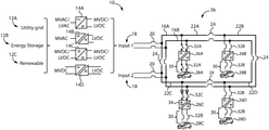
- FIG. 1 is a schematic view of a multiple vehicle electric charging system
- FIG. 2 is a schematic view of another charging system
- FIG. 3 is a schematic view of another charging system.
- electric power may be supplied by one or more conventional power sources 12 , such as a utility grid 12 A, an energy storage 12 B (e.g., batteries) or renewable sources 12 C (e.g., photovoltaic panels or wind turbines). Electric power from a power source 12 is then converted using a first electric converter 14 and supplied to a ring bus 16 , or conductive ring 16 .
- Various types of converters 12 may be used.
- the converter 14 may be an AC to DC converter 14 A, B that converts an AC voltage to a DC voltage.
- the power source 12 is a DC power source 12 B, C (e.g., an energy storage 12 B, renewable resource 12 C or a utility grid)
- the converter 14 may be a DC to DC converter 14 C, D that converts a DC voltage of one voltage level to a DC voltage of another voltage level.
- the voltage levels of the input and output of the converter 14 are similar (e.g., LV-LV or MV-MV)
- the converter 14 A, C may be non-isolated with a direct bus between the two sides of the converter 14 A, C.
- the converter 14 B, D may be provided with isolation (e.g., a transformer) between the two sides of the converter 14 B, D.
- isolation e.g., a transformer
- more than one power input 18 may be provided to the ring bus 16 if desired. If multiple inputs 18 are provided to the ring bus 16 , it may be desirable for each input 18 to have a different power source 12 and different type of converter 14 to avoid both inputs 18 from failing at the same time for the same reason.
- one input 18 may be supplied with power from a utility grid 12 A through an AC to DC converter 14 A, B.
- Another input 18 may then be supplied with power from an energy storage 12 B through a DC to DC converter 14 C, D.
- each input 18 is provided with a circuit breaker 20 between the respective first converter 14 and the ring bus 16 .
- the ring bus 16 is supplied with DC power. Because the distribution system 36 is DC powered, the cables of the ring bus 16 may be smaller than cables used in an AC distribution system. Power losses in the ring bus 16 may also be less than in an AC distribution system. The DC ring bus 16 may also be maintained at a higher voltage level than AC distribution systems. As illustrated, it may be preferable for the ring bus 16 to include two corresponding ring buses 16 A, B, where one ring bus 16 A is the positive bus 16 A (or higher voltage potential) and the other ring bus 16 B is the negative bus 16 B (or lower voltage potential).
- the ring buses 16 are separated into a number of DC buses 22 A-D, or ring sections 22 A-D, by a series of circuit breakers 24 , or electrical breakers 24 . That is, each DC bus 22 is defined by two circuit breakers 24 with one circuit breaker 24 at each opposite end of the DC bus 22 . Naturally, one circuit breaker 24 may be shared by two adjacent DC buses 22 such that the circuit breaker 24 defines one end of two different DC buses 22 . Thus, the DC buses 22 and circuit breakers 24 connected in serial define a length of the ring bus 16 , and preferably, are connected in an entire interconnected ring 16 . Where two ring buses 16 A, B are provided, it may be preferred for the arrangement of circuit breakers 24 and DC buses 22 to directly correspond in both of the ring buses 16 A, B.
- a plurality of second electrical converters 26 A-D may be connected to the various DC buses 22 A-D around the ring bus 16 .
- the second electrical converters 26 are DC converters 26 that preferably convert the DC voltage of the ring bus 16 to a DC voltage of another level suitable for the electric vehicles 28 A-D being charged by the system 10 .
- the DC ring bus 16 is maintained at a high DC voltage, it may be desirable for the second electrical converters 26 to convert the DC voltage to a lower voltage to supply the electric vehicles 28 .
- any conventional converter utilizing high-speed semiconductor switches e.g., MOSFET, IGBT or IGCT
- An example of a conventional converter that uses power semiconductor switches to convert electricity may be found in U.S. Pat. No. 9,789,774, which is incorporated herein by reference.
- a plurality of second converters 26 may be connected to different DC buses 22 of the ring bus 16 .
- each second converter 26 illustrated in FIG. 1 is connected to a single electric vehicle 28 , it is possible that each second converter 26 could supply power to multiple electric vehicles 28 if desired.
- each of the second converters 26 converts the electric power of the ring bus 16 to electric power that is usable by an electric vehicle 28 to charge the storage battery therein.
- a charge cable 30 is provided to connect each of the second converters 26 to an electric vehicle 28 for charging. As shown, it is not necessary for all of the second converters 26 to be of a matching type.
- each of the second converters 26 is provided with an electrical breaker 32 between the converter 26 and the ring bus 16 , and more preferably, also between the converter 26 and the electric vehicle 28 .
- isolators 32 A may be installed at the inputs and outputs of the converter 26 A.
- all input and output isolators 32 A of the converter 26 A open to isolate the converter 26 A.
- the input isolators 32 A open to isolate the converter 26 A from the faulted DC bus 22 A.
- the output isolators 32 A open to isolate the faulted charger or vehicle 28 A. If the second converter 26 B does not have fault interruption capability, DC circuit breakers 32 B are preferably installed at the input and output of the converter 26 B. The DC circuit breakers 32 B will also open to provide isolation as described above. Alternatively, if a charger only allows unidirectional power flow from the DC bus 22 C to the electric vehicle 28 C, a diode and isolator 32 C can be installed in series at the input of the converter 26 C. In this case, if there is a fault on the DC bus 22 C, the diode 32 C blocks electric power from backfeeding into the DC bus 22 C. The isolator 32 C also opens for galvanic isolation. Faults inside the converter 26 C may be handled by fuses 34 . Faults in the charger past the converter 26 C or in the electric vehicle 28 C can be handled by output DC circuit breakers 32 B.
- the second converters 26 may be connected to different DC buses 22 of the ring bus 16 to provide further isolation between each of the second converters 26 , DC buses 22 and first converters 14 .
- the following is an example of how the described distribution system 36 can improve reliability of the charging system 10 .
- a fault may occur in one of the DC buses 22 B or in a second converter 26 B connected to a DC bus 22 B.
- the increased current flow causes the circuit breakers 24 at both ends of the respective DC bus 22 B to open. While it is possible that both circuit breakers 24 may open simultaneously, it is also possible that there could be a slight delay between the opening of each circuit breaker 24 .
- one of the second converters 26 A remains connected to the first converters 14 on one side of the faulted DC bus 22 B, and other second converters 26 C, D remain connected to the first converters 14 on the other side of the faulted bus 22 B.
- the remaining second converters 26 A, C, D can continue charging electric vehicles 28 A, C, D coupled thereto. It is understood that where a fault occurs in one of the second converters 26 , it may not be necessary for the respective DC bus circuit breakers 24 to open since the respective isolator 32 between the second converter 26 and the bus 22 may open to isolate the faulted second converter 26 .
- a fault may occur in one of the first converters 14 , the DC bus 22 connected to one of the first converters 14 , or a second converter 26 connected to a DC bus 22 connected to a first converter 14 .
- faults occurring in the second converters 26 will be separately isolated as described above, and faults occurring in a first converter 14 will be separately isolated with input circuit breakers 20 .
- any of these faults, and particularly a fault in the DC bus 22 itself may be isolated as described above with the circuit breakers 24 opening at opposite ends of the affected DC bus 22 .
- the first converter 14 connected thereto will be isolated from the other second converters 26 due to the open circuit breakers 24 at the ends of the DC bus 22 .
- the remaining second converters 26 will remain connected to the other first converter 14 .
- power may still be supplied to the other second converters 26 for charging electric vehicles 28 coupled thereto.
- a utility grid 12 A may be connected through an AC-DC converter and DC-DC converter 14 B to one of the DC buses 22 A.
- a battery 12 B may also be connected to another DC bus 22 C through a DC-DC converter 14 C.
- the utility grid 12 A may also be connected to yet another DC bus 22 D through a different AC-DC converter and DC-DC converter 14 B.
- the respective input circuit breakers 20 may open to isolate the fault while power may still be supplied to the ring bus 16 through the remaining first converters 14 .
- the remaining portion of the ring bus 16 can be supplied with power from the remaining first converters 14 .
- the utility grid 12 A may still supply power to the ring bus 16 through another first converter 14 B and DC bus 22 D.
- FIG. 3 it may also be desirable to have multiple second converters 26 connected to a DC bus 22 to charge multiple electric vehicles 28 .
- two second converters 26 are connected to each of the DC buses 22 with second converters 26 , although more than two second converters 26 could also be connected to each DC bus 22 .
- a fault in one of the DC buses 22 A-D with second converters 26 will disconnect all of the second converters 26 that are connected to the faulted bus 22 from the ring bus 16 and from the first converters 14 .
- a greater number of second converters 26 may be provided in this arrangement with less cost.
- each of the first converters 14 may also be desirable to connect to a separate DC bus 22 E, F that is not connected to any of the second converters 26 .
- each first converter 14 may also be connected to a separate DC bus 22 E, F from the other first converters 14 .
- the second converters 26 will remain connected to at least one other first converter 14 C to allow continued charging.
- the respective bus 22 B may be disconnected from the ring bus 16 but the remaining second converters 26 A, C, D will remain connected to the first converters 14 B, C to continue receiving power.
- first converters 14 and second converters 26 may be desirable to also provide communication between the power sources 12 , first converters 14 and second converters 26 (e.g., 5G, WIFI or wired connections) in order to control the breakers 20 based on such communication.
- V2X Vehicle-to-Everything
- grid management functionality may be incorporated into the charging system 10 .
Abstract
Description
Claims (20)
Priority Applications (3)
| Application Number | Priority Date | Filing Date | Title |
|---|---|---|---|
| US16/715,716 US11230202B2 (en) | 2019-12-16 | 2019-12-16 | Multiple vehicle charging system |
| DE112020006179.5T DE112020006179T5 (en) | 2019-12-16 | 2020-12-10 | CHARGING SYSTEM FOR MULTIPLE VEHICLES |
| PCT/US2020/064246 WO2021126659A1 (en) | 2019-12-16 | 2020-12-10 | Multiple vehicle charging system |
Applications Claiming Priority (1)
| Application Number | Priority Date | Filing Date | Title |
|---|---|---|---|
| US16/715,716 US11230202B2 (en) | 2019-12-16 | 2019-12-16 | Multiple vehicle charging system |
Publications (2)
| Publication Number | Publication Date |
|---|---|
| US20210178918A1 US20210178918A1 (en) | 2021-06-17 |
| US11230202B2 true US11230202B2 (en) | 2022-01-25 |
Family
ID=76316580
Family Applications (1)
| Application Number | Title | Priority Date | Filing Date |
|---|---|---|---|
| US16/715,716 Active 2040-07-20 US11230202B2 (en) | 2019-12-16 | 2019-12-16 | Multiple vehicle charging system |
Country Status (3)
| Country | Link |
|---|---|
| US (1) | US11230202B2 (en) |
| DE (1) | DE112020006179T5 (en) |
| WO (1) | WO2021126659A1 (en) |
Cited By (1)
| Publication number | Priority date | Publication date | Assignee | Title |
|---|---|---|---|---|
| US20230011000A1 (en) * | 2021-07-08 | 2023-01-12 | Enersys Delaware Inc. | Direct current fast charging systems with grid tied energy storage systems |
Families Citing this family (2)
| Publication number | Priority date | Publication date | Assignee | Title |
|---|---|---|---|---|
| US11688889B2 (en) * | 2021-11-10 | 2023-06-27 | Beta Air, Llc | Monitoring system and method for charging multiple battery packs in an electric aircraft |
| EP4274046A1 (en) * | 2022-05-04 | 2023-11-08 | Abb Schweiz Ag | Dc distribution system and method for distributing power |
Citations (21)
| Publication number | Priority date | Publication date | Assignee | Title |
|---|---|---|---|---|
| WO2001097360A2 (en) * | 2000-06-14 | 2001-12-20 | Aerovironment Inc. | Battery charging system and method |
| JP2004129351A (en) * | 2002-10-01 | 2004-04-22 | Toshiba Corp | Auxiliary power supply device for vehicle |
| US7256516B2 (en) * | 2000-06-14 | 2007-08-14 | Aerovironment Inc. | Battery charging system and method |
| US20100145535A1 (en) * | 2008-12-05 | 2010-06-10 | Tyler Richard M | Intra-vehicle charging system for use in recharging vehicles equipped with electrically powered propulsion systems |
| US8072184B2 (en) | 2009-06-02 | 2011-12-06 | Coulomb Technologies, Inc. | Overcurrent and ground fault protection in a networked charging station for electric vehicles |
| US20130069592A1 (en) * | 2010-05-19 | 2013-03-21 | Abb B.V. | Charging system for electric vehicles |
| JP2014064397A (en) * | 2012-09-21 | 2014-04-10 | Kyushu Railway Co | Electric power system for electric motor vehicle, and electric supply control method |
| CN103795132A (en) | 2014-02-28 | 2014-05-14 | 东北电力大学 | Modularization multiport type electric car quick charging station based on high-frequency isolation technology |
| EP2815913A1 (en) | 2013-06-18 | 2014-12-24 | Eutecne S.p.A. | Recharging system for electric vehicles |
| WO2016169766A1 (en) * | 2015-04-23 | 2016-10-27 | Continental Automotive Gmbh | Power circuit for power supply in an electrically driven vehicle and stationary energy supply system |
| DE102015110023A1 (en) | 2015-06-23 | 2016-12-29 | Dr. Ing. H.C. F. Porsche Aktiengesellschaft | Charging station and method for charging a plug-in motor vehicle at a charging station |
| US9783071B2 (en) | 2009-07-27 | 2017-10-10 | Innogy Se | Device and method for providing a quantity of energy in said supply device for consumer |
| US9789774B2 (en) | 2015-04-02 | 2017-10-17 | Hyundai Motor Company | Charger for vehicles |
| US20180037121A1 (en) * | 2016-08-03 | 2018-02-08 | Solarcity Corporation | Energy generation and storage system with electric vehicle charging capability |
| EP3339084A1 (en) | 2016-12-23 | 2018-06-27 | ABB Schweiz AG | Electric vehicle charging station with transformer comprising multiple secondary windings |
| WO2018126393A1 (en) | 2017-01-05 | 2018-07-12 | General Electric Company | Dc fast charging station for electric vehicles |
| US20180290548A1 (en) | 2017-04-05 | 2018-10-11 | Semikron Elektronik Gmbh & Co. Kg | Power converted arrangement for feeding vehicles and installation comprising the same |
| WO2018192960A1 (en) * | 2017-04-20 | 2018-10-25 | Abb Schweiz Ag | Charging device for electric vehicles |
| WO2018202462A1 (en) | 2017-05-05 | 2018-11-08 | Siemens Aktiengesellschaft | Electric charging system and method |
| JP2018182925A (en) * | 2017-04-14 | 2018-11-15 | 清水建設株式会社 | Power supply system |
| US10391870B2 (en) | 2016-12-09 | 2019-08-27 | Dr. Ing. H.C. F. Porsche Aktiengesellschaft | Modular power electronics system for charging an electrically operated vehicle |
-
2019
- 2019-12-16 US US16/715,716 patent/US11230202B2/en active Active
-
2020
- 2020-12-10 WO PCT/US2020/064246 patent/WO2021126659A1/en active Application Filing
- 2020-12-10 DE DE112020006179.5T patent/DE112020006179T5/en active Pending
Patent Citations (21)
| Publication number | Priority date | Publication date | Assignee | Title |
|---|---|---|---|---|
| US7256516B2 (en) * | 2000-06-14 | 2007-08-14 | Aerovironment Inc. | Battery charging system and method |
| WO2001097360A2 (en) * | 2000-06-14 | 2001-12-20 | Aerovironment Inc. | Battery charging system and method |
| JP2004129351A (en) * | 2002-10-01 | 2004-04-22 | Toshiba Corp | Auxiliary power supply device for vehicle |
| US20100145535A1 (en) * | 2008-12-05 | 2010-06-10 | Tyler Richard M | Intra-vehicle charging system for use in recharging vehicles equipped with electrically powered propulsion systems |
| US8072184B2 (en) | 2009-06-02 | 2011-12-06 | Coulomb Technologies, Inc. | Overcurrent and ground fault protection in a networked charging station for electric vehicles |
| US9783071B2 (en) | 2009-07-27 | 2017-10-10 | Innogy Se | Device and method for providing a quantity of energy in said supply device for consumer |
| US20130069592A1 (en) * | 2010-05-19 | 2013-03-21 | Abb B.V. | Charging system for electric vehicles |
| JP2014064397A (en) * | 2012-09-21 | 2014-04-10 | Kyushu Railway Co | Electric power system for electric motor vehicle, and electric supply control method |
| EP2815913A1 (en) | 2013-06-18 | 2014-12-24 | Eutecne S.p.A. | Recharging system for electric vehicles |
| CN103795132A (en) | 2014-02-28 | 2014-05-14 | 东北电力大学 | Modularization multiport type electric car quick charging station based on high-frequency isolation technology |
| US9789774B2 (en) | 2015-04-02 | 2017-10-17 | Hyundai Motor Company | Charger for vehicles |
| WO2016169766A1 (en) * | 2015-04-23 | 2016-10-27 | Continental Automotive Gmbh | Power circuit for power supply in an electrically driven vehicle and stationary energy supply system |
| DE102015110023A1 (en) | 2015-06-23 | 2016-12-29 | Dr. Ing. H.C. F. Porsche Aktiengesellschaft | Charging station and method for charging a plug-in motor vehicle at a charging station |
| US20180037121A1 (en) * | 2016-08-03 | 2018-02-08 | Solarcity Corporation | Energy generation and storage system with electric vehicle charging capability |
| US10391870B2 (en) | 2016-12-09 | 2019-08-27 | Dr. Ing. H.C. F. Porsche Aktiengesellschaft | Modular power electronics system for charging an electrically operated vehicle |
| EP3339084A1 (en) | 2016-12-23 | 2018-06-27 | ABB Schweiz AG | Electric vehicle charging station with transformer comprising multiple secondary windings |
| WO2018126393A1 (en) | 2017-01-05 | 2018-07-12 | General Electric Company | Dc fast charging station for electric vehicles |
| US20180290548A1 (en) | 2017-04-05 | 2018-10-11 | Semikron Elektronik Gmbh & Co. Kg | Power converted arrangement for feeding vehicles and installation comprising the same |
| JP2018182925A (en) * | 2017-04-14 | 2018-11-15 | 清水建設株式会社 | Power supply system |
| WO2018192960A1 (en) * | 2017-04-20 | 2018-10-25 | Abb Schweiz Ag | Charging device for electric vehicles |
| WO2018202462A1 (en) | 2017-05-05 | 2018-11-08 | Siemens Aktiengesellschaft | Electric charging system and method |
Non-Patent Citations (8)
| Title |
|---|
| Camurca, Luis, et al., "Design of a Medium Voltage DC Fast Charging Station with Grid Voltage Regulation and Central Modular Multilevel Converter" 2018 IEEE, 978-1-4799-7312-5/18, pp. 2798-2804, 7 pp. |
| De Doncker, Dr. Rik W., "Fast Charging (350kW) for Electric Vehicles—Possibilities and Issues", 2019, RWTH Aachen University, Power Generation and Storage Systems, 39 pp. |
| Hinz, Ame, et al., "Impact and Opportunities of Medium—Voltage DC Grids in Urban Railway Systems", Institute for Power Generation and Storage Systems E.ON Energy Research Center, 2016, RWTH Aachen University, 10 pp. |
| Hoffmann, Felix, et al., "Modular EV Fast Charging Station Architectures based on Multiphase-Medium-Frequency Transformer", 2018 IEEE, 978-1-5090-6684-1/18, pp. 1327-1332, 6 pp. |
| Infrastructure Working Council Meeting—Day Two Presentations, Washington, D.C., Jun. 8, 2017, Electric Power Research Institute, 38 pp. |
| Nademi, Hamed, et al., "Interfacing an Electric Vehicle to the Grid with Modular Conversion Unit: A Case Study of a Charging Station and its Control Framework", 2018 IEEE, 978-1-5090-6684-1/18, pp. 5171-5176, 6 pp. |
| Nair, Arun Chandrasekharan, et al., "A Solid State Transformer based Fast Charging Station for all Categories of Electric Vehicles" 2018 IEEE, 978-1-5090-6684-1/18, pp. 1989-1994, 6 pp. |
| United States Patent & Trademark Office, The International Search Report and The Written Opinion issued in corresponding International application No. PCT/US2020/064246, dated Mar. 23, 2021, 7 pp. |
Cited By (1)
| Publication number | Priority date | Publication date | Assignee | Title |
|---|---|---|---|---|
| US20230011000A1 (en) * | 2021-07-08 | 2023-01-12 | Enersys Delaware Inc. | Direct current fast charging systems with grid tied energy storage systems |
Also Published As
| Publication number | Publication date |
|---|---|
| DE112020006179T5 (en) | 2022-11-10 |
| US20210178918A1 (en) | 2021-06-17 |
| WO2021126659A1 (en) | 2021-06-24 |
Similar Documents
| Publication | Publication Date | Title |
|---|---|---|
| US11532947B2 (en) | Combination wind/solar DC power system | |
| US11362525B2 (en) | Full direct-current boost/buck power transmission system and method | |
| US11230202B2 (en) | Multiple vehicle charging system | |
| US8552590B2 (en) | Energy management system and grid-connected energy storage system including the energy management system | |
| US20120019203A1 (en) | Energy storage and vehicle charging system and method of operation | |
| US20050006958A1 (en) | Grid-connected power systems having back-up power sources and methods of providing back-up power in grid-connected power systems | |
| US20110266876A1 (en) | Power supply system and photovoltaic device therefor | |
| US10434886B2 (en) | Method and arrangement for charging of vehicle accumulators | |
| US9825470B2 (en) | Multi-source power converter | |
| US10284115B2 (en) | Inverter system | |
| CN112350588A (en) | Power supply device applied to solid-state transformer framework and three-phase power supply system | |
| US20230037976A1 (en) | Power supply and distribution system | |
| CN102340138A (en) | Power supply and distribution system for building | |
| CN110588389A (en) | Charging device and charging system for charging and discharging traction battery of electric automobile | |
| CN108141041B (en) | Power transmission device and method for operating a power transmission device | |
| CN105762899A (en) | Charging system for AC-DC distribution intelligent charging station | |
| KR20170053033A (en) | Hybrid Distribution Network System | |
| EP3915824A1 (en) | Method and system for vehicle-to-vehicle charging of electric vehicles | |
| CN117060566A (en) | AC/DC hybrid micro-grid system | |
| US20220166219A1 (en) | Systems and methods for modular power conversion units in power supply systems | |
| KR20080001239U (en) | System for supply the source of electricity using the direct-current dynamo | |
| US20180083453A1 (en) | Power converting module, power generating system, and control method thereof | |
| CN102938580B (en) | Portable multifunctional power supply for emergency repair | |
| Song et al. | Design considerations for energy storage power electronics interfaces for high penetration of renewable energy sources | |
| Ajaei et al. | Hybrid AC/DC microgrid configurations for a net-zero energy community |
Legal Events
| Date | Code | Title | Description |
|---|---|---|---|
| FEPP | Fee payment procedure |
Free format text: ENTITY STATUS SET TO UNDISCOUNTED (ORIGINAL EVENT CODE: BIG.); ENTITY STATUS OF PATENT OWNER: LARGE ENTITY |
|
| AS | Assignment |
Owner name: ABB SCHWEIZ AG, SWITZERLAND Free format text: ASSIGNMENT OF ASSIGNORS INTEREST;ASSIGNOR:QI, LI;REEL/FRAME:052097/0862 Effective date: 20200220 |
|
| STPP | Information on status: patent application and granting procedure in general |
Free format text: DOCKETED NEW CASE - READY FOR EXAMINATION |
|
| STPP | Information on status: patent application and granting procedure in general |
Free format text: NOTICE OF ALLOWANCE MAILED -- APPLICATION RECEIVED IN OFFICE OF PUBLICATIONS |
|
| STPP | Information on status: patent application and granting procedure in general |
Free format text: PUBLICATIONS -- ISSUE FEE PAYMENT VERIFIED |
|
| STCF | Information on status: patent grant |
Free format text: PATENTED CASE |
|
| AS | Assignment |
Owner name: ABB B.V., NETHERLANDS Free format text: ASSIGNMENT OF ASSIGNORS INTEREST;ASSIGNOR:ABB SCHWEIZ AG;REEL/FRAME:062205/0860 Effective date: 20221010 |
|
| AS | Assignment |
Owner name: ABB E-MOBILITY B.V., NETHERLANDS Free format text: CHANGE OF NAME;ASSIGNOR:ABB B.V.;REEL/FRAME:062320/0490 Effective date: 20220101 |