US11230038B2 - Injection molding apparatus for inserting atypical stiffener - Google Patents
Injection molding apparatus for inserting atypical stiffener Download PDFInfo
- Publication number
- US11230038B2 US11230038B2 US16/297,318 US201916297318A US11230038B2 US 11230038 B2 US11230038 B2 US 11230038B2 US 201916297318 A US201916297318 A US 201916297318A US 11230038 B2 US11230038 B2 US 11230038B2
- Authority
- US
- United States
- Prior art keywords
- stiffener
- elastic
- clamper
- atypical
- injection molding
- Prior art date
- Legal status (The legal status is an assumption and is not a legal conclusion. Google has not performed a legal analysis and makes no representation as to the accuracy of the status listed.)
- Active, expires
Links
Images


Classifications
-
- B—PERFORMING OPERATIONS; TRANSPORTING
- B29—WORKING OF PLASTICS; WORKING OF SUBSTANCES IN A PLASTIC STATE IN GENERAL
- B29C—SHAPING OR JOINING OF PLASTICS; SHAPING OF MATERIAL IN A PLASTIC STATE, NOT OTHERWISE PROVIDED FOR; AFTER-TREATMENT OF THE SHAPED PRODUCTS, e.g. REPAIRING
- B29C45/00—Injection moulding, i.e. forcing the required volume of moulding material through a nozzle into a closed mould; Apparatus therefor
- B29C45/03—Injection moulding apparatus
- B29C45/04—Injection moulding apparatus using movable moulds or mould halves
- B29C45/0408—Injection moulding apparatus using movable moulds or mould halves involving at least a linear movement
-
- B—PERFORMING OPERATIONS; TRANSPORTING
- B29—WORKING OF PLASTICS; WORKING OF SUBSTANCES IN A PLASTIC STATE IN GENERAL
- B29C—SHAPING OR JOINING OF PLASTICS; SHAPING OF MATERIAL IN A PLASTIC STATE, NOT OTHERWISE PROVIDED FOR; AFTER-TREATMENT OF THE SHAPED PRODUCTS, e.g. REPAIRING
- B29C45/00—Injection moulding, i.e. forcing the required volume of moulding material through a nozzle into a closed mould; Apparatus therefor
- B29C45/14—Injection moulding, i.e. forcing the required volume of moulding material through a nozzle into a closed mould; Apparatus therefor incorporating preformed parts or layers, e.g. injection moulding around inserts or for coating articles
- B29C45/14065—Positioning or centering articles in the mould
-
- B—PERFORMING OPERATIONS; TRANSPORTING
- B29—WORKING OF PLASTICS; WORKING OF SUBSTANCES IN A PLASTIC STATE IN GENERAL
- B29C—SHAPING OR JOINING OF PLASTICS; SHAPING OF MATERIAL IN A PLASTIC STATE, NOT OTHERWISE PROVIDED FOR; AFTER-TREATMENT OF THE SHAPED PRODUCTS, e.g. REPAIRING
- B29C45/00—Injection moulding, i.e. forcing the required volume of moulding material through a nozzle into a closed mould; Apparatus therefor
- B29C45/14—Injection moulding, i.e. forcing the required volume of moulding material through a nozzle into a closed mould; Apparatus therefor incorporating preformed parts or layers, e.g. injection moulding around inserts or for coating articles
- B29C45/14467—Joining articles or parts of a single article
-
- B—PERFORMING OPERATIONS; TRANSPORTING
- B29—WORKING OF PLASTICS; WORKING OF SUBSTANCES IN A PLASTIC STATE IN GENERAL
- B29C—SHAPING OR JOINING OF PLASTICS; SHAPING OF MATERIAL IN A PLASTIC STATE, NOT OTHERWISE PROVIDED FOR; AFTER-TREATMENT OF THE SHAPED PRODUCTS, e.g. REPAIRING
- B29C45/00—Injection moulding, i.e. forcing the required volume of moulding material through a nozzle into a closed mould; Apparatus therefor
- B29C45/17—Component parts, details or accessories; Auxiliary operations
- B29C45/26—Moulds
-
- B—PERFORMING OPERATIONS; TRANSPORTING
- B29—WORKING OF PLASTICS; WORKING OF SUBSTANCES IN A PLASTIC STATE IN GENERAL
- B29C—SHAPING OR JOINING OF PLASTICS; SHAPING OF MATERIAL IN A PLASTIC STATE, NOT OTHERWISE PROVIDED FOR; AFTER-TREATMENT OF THE SHAPED PRODUCTS, e.g. REPAIRING
- B29C45/00—Injection moulding, i.e. forcing the required volume of moulding material through a nozzle into a closed mould; Apparatus therefor
- B29C45/14—Injection moulding, i.e. forcing the required volume of moulding material through a nozzle into a closed mould; Apparatus therefor incorporating preformed parts or layers, e.g. injection moulding around inserts or for coating articles
- B29C45/14065—Positioning or centering articles in the mould
- B29C2045/14098—Positioning or centering articles in the mould fixing or clamping inserts having variable dimensions
-
- B—PERFORMING OPERATIONS; TRANSPORTING
- B29—WORKING OF PLASTICS; WORKING OF SUBSTANCES IN A PLASTIC STATE IN GENERAL
- B29C—SHAPING OR JOINING OF PLASTICS; SHAPING OF MATERIAL IN A PLASTIC STATE, NOT OTHERWISE PROVIDED FOR; AFTER-TREATMENT OF THE SHAPED PRODUCTS, e.g. REPAIRING
- B29C45/00—Injection moulding, i.e. forcing the required volume of moulding material through a nozzle into a closed mould; Apparatus therefor
- B29C45/14—Injection moulding, i.e. forcing the required volume of moulding material through a nozzle into a closed mould; Apparatus therefor incorporating preformed parts or layers, e.g. injection moulding around inserts or for coating articles
- B29C45/14065—Positioning or centering articles in the mould
- B29C2045/14163—Positioning or centering articles in the mould using springs being part of the positioning means
-
- B—PERFORMING OPERATIONS; TRANSPORTING
- B29—WORKING OF PLASTICS; WORKING OF SUBSTANCES IN A PLASTIC STATE IN GENERAL
- B29L—INDEXING SCHEME ASSOCIATED WITH SUBCLASS B29C, RELATING TO PARTICULAR ARTICLES
- B29L2031/00—Other particular articles
- B29L2031/30—Vehicles, e.g. ships or aircraft, or body parts thereof
- B29L2031/3044—Bumpers
Definitions
- the present invention relates to an injection molding apparatus for inserting atypical stiffener. More particularly, the present invention relates to an injection molding apparatus for inserting atypical stiffener in which presses elastically both sides of the atypical stiffener B in association with the size of an atypical stiffener B to hold it in position between an upper core and an under core.
- injection molding refers to manufacturing an injection molding product of a desired shape by injecting and hardening a melted synthetic resin melt mixed with a thermoplastic resin, a thermosetting resin, a binder or the like into a mold, and the injection molding product is used in various fields ranging from household appliances to smart phones, various building materials and vehicle parts.
- the injection molding product produced by injection molding of a synthetic resin material requires high strength, for example, to withstand impact, it is manufactured by inserting a stiffener.
- An example of an injection molding product in which such a stiffener is inserted may be a bumper beam used as a vehicle parts.
- FIG. 1A is an exploded perspective view showing a configuration of a conventional automotive bumper assembly introduced in the related art
- FIG. 1B is a perspective view showing a plastic composite material bumper beam for a vehicle according to the related art document.
- a typical automotive bumper assembly introduced in the related art may include a bumper cover 10 that encloses the entire front and rear of the vehicle body as shown in FIG. 1A , and an energy absorber 20 for absorbing the sluggishness and impact energy of the bumper cover 10 , a bumper beam 30 positioned behind the energy absorber 20 for protecting the vehicle body from the impact and a stay 40 for fixing and supporting the bumper beam 30 to the vehicle.
- the bumper beam 30 further strengthens the force that can withstand an external impact, protecting the vehicle body and assuring occupant safety.
- the automotive plastic composite material bumper beam may include a body of a bumper beam 30 made of a fiber-reinforced plastic composite material and the stiffener 35 inserted into the body of the bumper beam 30 , and the inserted stiffener 35 is disposed long along the longitudinal direction of the body of the bumper beam 30 with a loop shape as shown in FIG. 1B .
- the stiffener 35 may be made of a material having a higher rigidity than that of the main material provided as the material of the main body of the bumper beam 30 , for example, the stiffener 35 may be made of fiber reinforced plastic composites, glass fiber, natural fiber, carbon fiber, aramid fiber, ultra high molecular weight polyethylene fiber (UHMWPE Fiber), and the cross-sectional structure, thickness, shape, and the like may vary.
- the stiffener 35 may be made of fiber reinforced plastic composites, glass fiber, natural fiber, carbon fiber, aramid fiber, ultra high molecular weight polyethylene fiber (UHMWPE Fiber), and the cross-sectional structure, thickness, shape, and the like may vary.
- the plastic composite material bumper beam according to the related art does not describe what type of device the stiffener 35 is to be used when inserting the stiffener 35 .
- the structure of the stiffener 35 the structure such as the thickness or the shape is various, and the structure is irregular, whether different apparatuses are required or whether different cores are used.
- each core or the like according to the sectional structure of the stiffener 35 or the thickness or shape of the stiffener 35 is used in the conventional technology, and the productivity is remarkably reduced due to mobilization of various facilities.
- Various aspects of the present invention are directed to providing an injection molding apparatus configured for inserting atypical stiffener in which an elastic clamper presses elastically both sides of the atypical stiffener in association with the size of an atypical stiffener to hold it in position between an upper core and an under core (if the size is large, it retreats backward by elasticity, and if the size is small, it moves forward).
- Various aspects of the present invention are directed to providing an injection molding apparatus configured for inserting atypical stiffener configured for securely and accurately holding correct position of the atypical stiffener inserted into the injection molding product by elastically pressing the atypical stiffener by one side elastic clamper and the other side elastic clamper from both sides even if the size of the atypical stiffener is different (even if the size of the atypical stiffener is uneven).
- Various aspects of the present invention are directed to providing an injection molding apparatus configured for inserting atypical stiffener in which the vertical supporter and the horizontal elasticity bundle are mounted to make under mold and under core embedding easier when the one side elastic clamper and the other side elastic clamper are provided, a horizontal elastic bundle is mounted to the upper end portion of the vertical supporter while being supported by the under mold.
- Various aspects of the present invention are directed to providing an injection molding apparatus configured for inserting atypical stiffener in which the horizontal elasticity bundle of the one side elastic clamper and the horizontal elasticity bundle of the other side elastic clamper can elastically press at the upper wide and the under narrow intervals on both sides of the atypical stiffener, whereby the synthetic resin melt is cured in the under mold and the upper mold, therefore it may be rapidly separated from the horizontal elastic bundle on both sides when it is removed in the upward direction thereof.
- Various aspects of the present invention are directed to providing an injection molding apparatus configured for inserting atypical stiffener in which the vertical supporters of the one side elastic clamper and the other side elastic clamper are fixed close to the lower end portion of the under mold, respectively, and then are inserted into the inclination holes of the tilt bracket and are inclined at mutually different distances toward the upper end portion of the under mold, enables rigid support of the horizontal elastic bundle, therefore it is possible to insert an atypical stiffener without shaking at the time of mass production of the injection molding products.
- Various aspects of the present invention are directed to providing an injection molding apparatus configured for inserting atypical stiffener in which elastic pins and springs and wrench bolts are used at all times in a fixed bundle to assure the ease of assembly through easy embedding into the under core, and, the elasticity of the spring supported by the wrench bolt coupled with the screw groove of the wide tunnel, and the elastic pins are fixed to the stopper by the limiting jaw so that the side surface of the atypical stiffener is flexibly pressurized.
- Various aspects of the present invention are directed to providing an injection molding apparatus configured for inserting atypical stiffener configured for ensuring the smooth adhesion according to the size of the atypical stiffener.
- Various aspects of the present invention are directed to providing an injection molding apparatus configured for inserting atypical stiffener in which the narrow rod and wide rod of the vertical supporter are inserted into the narrow vertical grooves and the wide vertical grooves of the fixed bundle, and the fixing pin is inserted into the internal horizontal hole via the external horizontal hole in a state where the support step is in contact with the fixing step, and the horizontal elasticity bundle is easily embedded in the under core, therefore ensuring robust assembly.
- an injection molding apparatus configured for inserting atypical stiffener including an upper mold M 1 provided with an upper core C 1 and an under mold M 2 provided with an under core C 2 for manufacturing an injection molding product S by receiving synthetic resin melt and curing in a state in which an atypical stiffener B whose size is not constant is inserted, includes elastic clampers T supported by the under mold M 2 , embedded in the under core C 2 , interlocked with the size of the atypical stiffener B, and elastically pressurizing both sides to hold the atypical stiffener B to be inserted into a correct position between the upper core C 1 and the under core C 2 by the atypical stiffener B when the synthetic resin melt is introduced.
- the present invention is for elastically pressing both sides of an atypical stiffener by an elastic clamper in association with the size of an atypical stiffener to hold it in position between an upper core and an under core (if the size is large, it retreats backward by elasticity, and if the size is small, it moves forward).
- the present invention is for securely and accurately holding correct position of the atypical stiffener inserted into the injection molding product by elastically pressing the atypical stiffener by one side elastic clamper and the other side elastic clamper from both sides even if the size of the atypical stiffener is different (even if the size of the atypical stiffener is uneven).
- the present invention is for providing an injection molding apparatus configured for inserting atypical stiffener in which the vertical supporter and the horizontal elasticity bundle are mounted to make under mold and under core embedding easier when the one side elastic clamper and the other side elastic clamper are provided, a horizontal elastic bundle is mounted to the upper end portion of the vertical supporter while being supported by the under mold.
- the present invention is for providing an injection molding apparatus configured for inserting atypical stiffener in which the horizontal elasticity bundle of the one side elastic clamper and the horizontal elasticity bundle of the other side elastic clamper may be elastically pressed at the upper wide and the under narrow clearances on both sides of the atypical stiffener, whereby the synthetic resin melt is cured in the under mold and the upper mold, therefore it may be rapidly separated from the horizontal elastic bundle on both sides when it is removed in the upward direction thereof.
- the present invention is for providing an injection molding apparatus configured for inserting atypical stiffener in which the vertical supporters of the one side elastic clamper and the other side elastic clamper are fixed close to the lower end portion of the under mold, respectively, and then are inserted into the inclination holes of the tilt bracket and are inclined at mutually different distances toward the upper end portion of the under mold, enables rigid support of the horizontal elastic bundle, therefore it is possible to insert an atypical stiffener without shaking at the time of mass production of the injection molding products.
- the present invention is for providing an injection molding apparatus configured for inserting atypical stiffener in which elastic pins and springs and wrench bolts are used at all times in a fixed bundle to assure the ease of assembly through easy embedding into the under core, and, the elasticity of the spring supported by the wrench bolt coupled with the screw groove of the wide tunnel, and the elastic pins are fixed to the stopper by the limiting jaw so that the side surface of the atypical stiffener is flexibly pressurized, therefore, it is possible to ensure the smooth adhesion according to the size of the atypical stiffener.
- the present invention is for providing an injection molding apparatus configured for inserting atypical stiffener in which the narrow rod and wide rod of the vertical supporter are inserted into the narrow vertical grooves and the wide vertical grooves of the fixed bundle, and the fixing pin is inserted into the internal horizontal hole via the external horizontal hole in a state where the support step is in contact with the fixing step, and the horizontal elasticity bundle is easily embedded in the under core, therefore ensuring robust assembly.
- FIG. 1A is an exploded perspective view showing a configuration of a conventional automotive bumper assembly introduced in the conventional art.
- FIG. 1B is a perspective view showing a plastic composite material bumper beam for a vehicle according to the conventional art.
- FIG. 2A is a perspective view showing a bumper beam used in a vehicle as an example of an injection molding product for explaining an injection molding apparatus configured for inserting atypical stiffener according to an exemplary embodiment of the present invention.
- FIG. 2B is a perspective view showing a bumper beam used in a vehicle as an example of an injection molding product for explaining an injection molding apparatus configured for inserting atypical stiffener according to an exemplary embodiment of the present invention.
- FIG. 3A and FIG. 3B are exploded perspective views of an injection molding apparatus configured for inserting atypical stiffener according to an exemplary embodiment of the present invention, including an injection molding product viewed from above.
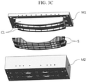
- FIG. 3C is an exploded perspective view of an injection molding apparatus configured for inserting atypical stiffener according to an exemplary embodiment of the present invention including an injection molding product viewed from below.
- FIG. 4A is a perspective view showing a pair of under cores in a state in which an under mold is dismantled to explain an injection molding apparatus configured for inserting atypical stiffener according to an exemplary embodiment of the present invention.
- FIG. 4B is a perspective view showing a pair of under cores and an elastic clamper in a state in which an under mold is dismantled to explain an injection molding apparatus configured for inserting atypical stiffener according to an exemplary embodiment of the present invention.
- FIG. 4C is a perspective view exemplarily illustrating a pair of under cores and elastic clamper for explaining an injection molding apparatus configured for inserting atypical stiffener according to an exemplary embodiment of the present invention.
- FIG. 4D is a partially enlarged perspective view of an under core and an elastic clamper for explaining an injection molding apparatus configured for inserting atypical stiffener according to an exemplary embodiment of the present invention.
- FIG. 5A is a side view of a pair of under cores and elastic clamper for explaining an injection molding apparatus configured for inserting atypical stiffener according to an exemplary embodiment of the present invention.
- FIG. 5B is a perspective view of an elastic clamper and a tilt bracket viewed from the side to explain an injection molding apparatus configured for inserting atypical stiffener according to an exemplary embodiment of the present invention.
- FIG. 5C is a perspective view exemplarily illustrating an elastic clamper and a tilt bracket holding an irregular reinforcing member to explain an injection molding apparatus configured for inserting atypical stiffener according to an exemplary embodiment of the present invention.
- FIG. 6A is a perspective view exemplarily illustrating a vertical supporter and a horizontal elastic bundle forming one side elastic clamper and the other side elastic clamper applied to an injection molding apparatus configured for inserting atypical stiffener according to an exemplary embodiment of the present invention.
- FIG. 6B is an exploded perspective view exemplarily illustrating a vertical supporter and a horizontal elastic bundle forming one side elastic clamper and the other side elastic clamper applied to an injection molding apparatus configured for inserting atypical stiffener according to an exemplary embodiment of the present invention.
- FIG. 2A is a perspective view showing a bumper beam used in a vehicle as an example of an injection molding product S for explaining an injection molding apparatus configured for inserting atypical stiffener according to an exemplary embodiment of the present invention
- FIG. 2B is a perspective view showing a bumper beam used in a vehicle as an example of an injection molding product S for explaining an injection molding apparatus configured for inserting atypical stiffener according to an exemplary embodiment of the present invention.
- an injection molding product S as a bumper beam to be used in vehicles is produced by molding a synthetic resin melt mixed and melted with a thermoplastic resin, a thermosetting resin, a binder, or the like into a mold, that is, an upper mold M 1 and an under mold M 2 and curing.
- atypical stiffener B it is possible to insert the atypical stiffener B by inserting it so that it can withstand the external impact (for preventing damage).
- the atypical stiffener B may be made of a fiber reinforced plastic composite material having high rigidity, glass fiber, natural fiber, carbon fiber, aramid fiber, ultra high molecular weight polyethylene Fiber (UHMWPE Fiber), however, it is extremely difficult to hold the mold in the upper mold M 1 and the under mold M 2 at the time of injection molding because the size of its volume or external diameter is not fixed (because the atypical stiffener is made by weave, twist, or braid).
- UHMWPE Fiber ultra high molecular weight polyethylene Fiber
- FIG. 3A and FIG. 3B are exploded perspective views of an injection molding apparatus configured for inserting atypical stiffener according to an exemplary embodiment of the present invention, including an injection molding product viewed from above
- FIG. 3C is an exploded perspective view of an injection molding apparatus configured for inserting atypical stiffener according to an exemplary embodiment of the present invention including an injection molding product viewed from below.
- an injection molding apparatus configured for inserting atypical stiffener according to an exemplary embodiment of the present invention includes an upper mold M 1 provided with an upper core C 1 and an under mold M 2 provided with an under core C 2 for manufacturing an injection molding product S by receiving synthetic resin melt and curing in a state in which an atypical stiffener B whose size is not constant is inserted.
- the upper core C 1 and the under core C 2 are combined in a male and female engagement with a gap and a gap in the upper mold M 1 and the under mold allow them to enter along clearances and crevices, therefore, as shown in FIG. 2A and FIG. 2B , it is possible to fabricate a structure in which the weight is reduced and the strength is strengthened by having a plate shape and a flesh or a rib as a whole.
- an atypical stiffener B is inserted to reinforce the strength.
- the atypical stiffener B is not easily fixed in the upper and lower molds M 1 and M 2 during injection molding as described above.
- FIG. 4A is a perspective view showing a pair of under cores in a state in which an under mold is dismantled to explain an injection molding apparatus configured for inserting atypical stiffener according to an exemplary embodiment of the present invention
- FIG. 4B is a perspective view showing a pair of under cores and an elastic clamper in a state in which an under mold is dismantled to explain an injection molding apparatus configured for inserting atypical stiffener according to an exemplary embodiment of the present invention
- FIG. 4C is a perspective view exemplarily illustrating a pair of under cores and elastic clamper for explaining an injection molding apparatus configured for inserting atypical stiffener according to an exemplary embodiment of the present invention
- FIG. 4D is a partially enlarged perspective view of an under core and an elastic clamper for explaining an injection molding apparatus configured for inserting atypical stiffener according to an exemplary embodiment of the present invention.
- the injection molding apparatus configured for inserting atypical stiffener includes elastic clampers T supported by the under mold M 2 , embedded in the under core C 2 , interlocked with the size of the atypical stiffener B, and elastically pressurizing both sides to hold the atypical stiffener B to be inserted into a correct position between the upper core C 1 and the under core C 2 by the atypical stiffener B when the synthetic resin melt is introduced.
- an elastic clamper T presses elastically both sides of the atypical stiffener B in association with the size of an atypical stiffener B to hold it in position between an upper core C 1 and an under core C 2 (if the size is large, it retreats backward by elasticity, and if the size is small, it moves forward), and therefore, the injection molding product S may be manufactured in large quantities without defects.
- FIG. 5A is a side view of a pair of under cores and elastic clamper device for explaining an injection molding apparatus configured for inserting atypical stiffener according to an exemplary embodiment of the present invention
- FIG. 5B is a perspective view of an elastic clamper device and an tilt bracket viewed from the side to explain an injection molding apparatus configured for inserting atypical stiffener according to an exemplary embodiment of the present invention
- FIG. 5C is a perspective view exemplarily illustrating an elastic clamper and a tilt bracket holding an irregular reinforcement member to explain an injection molding apparatus configured for inserting atypical stiffener according to an exemplary embodiment of the present invention.
- the elastic clamper device T applied to the injection molding apparatus configured for inserting atypical stiffener includes a side elastic clamper T 1 and the other side elastic clamper T 2 elastically pressing both sides of the atypical stiffener B therebetween.
- the present invention is for securely and accurately holding correct position of the atypical stiffener inserted into the injection molding product by elastically pressing the atypical stiffener by one side elastic clamper and the other side elastic clamper from both sides even if the size of the atypical stiffener is different (even if the size of the atypical stiffener is uneven), and therefore, the injection molding product S may be manufactured in large quantities without defects.
- the one side elastic clamper T 1 and the other side elastic clamper T 2 may be disposed one to one with the atypical stiffener B therebetween, they may be disposed to face each other while facing each other, or may be disposed to be opposed to each other as shown in FIG. 5C .
- FIG. 6A is a perspective view exemplarily illustrating a vertical supporter 50 and a horizontal elastic bundle 60 forming one side elastic clamper T 1 and the other side elastic clamper T 2 applied to an injection molding apparatus configured for inserting atypical stiffener according to an exemplary embodiment of the present invention
- FIG. 6B is an exploded perspective view exemplarily illustrating a vertical supporter 50 and a horizontal elastic bundle 60 forming one side elastic clamper T 1 and the other side elastic clamper T 2 applied to an injection molding apparatus configured for inserting atypical stiffener according to an exemplary embodiment of the present invention.
- the one side elastic clamper T 1 and the other side elastic clamper T 2 applied to the injection molding apparatus configured for inserting atypical stiffener includes a vertical supporter 50 mounted and erected on the under mold M 2 , respectively, and a horizontal elastic bundle 60 mounted on the upper end portion of the vertical supporter 50 and embedded in the under core C 2 to elastically pressurize both sides of the atypical stiffener B therebetween.
- the present invention is for providing an injection molding apparatus configured for inserting atypical stiffener in which the vertical supporter 50 and the horizontal elasticity bundle 60 are mounted to make under mold M 2 and under core C 2 embedding easier when the one side elastic clamper T 1 and the other side elastic clamper T 2 are provided, a horizontal elastic bundle 60 is mounted to the upper end portion of the vertical supporter 50 while being supported by the under mold M 2 .
- the vertical supporter 50 of the one side elastic clamper T 1 and the vertical supporter 50 of the other side elastic clamper T 2 are erected at a slope away from the lower end portion of the under mold M 2 toward the upper end portion thereof so that the horizontal elastic bundle 60 of the one side elastic clamper T 1 and the horizontal elastic bundle 60 of the other side elastic clamper T 2 can elastically pressurize the atypical stiffener B therebetween in upper wide and lower narrow clearances when inserting into the under core C 2 .
- the horizontal elasticity bundle 60 of the one side elastic clamper T 1 and the horizontal elasticity bundle 60 of the other side elastic clamper T 2 can elastically press at the upper wide and the under narrow clearances on both sides of the atypical stiffener B, whereby the synthetic resin melt is cured in the under mold M 2 and the upper mold M 1 , therefore it may be rapidly separated from the horizontal elastic bundle 60 on both sides when it is removed in the upward direction thereof.
- the elastic clamper device T further include a tilt bracket 70 connected at a middle end portion of the under mold M 2 and including inclination holes 71 which are obliquely drilled at an angle such which is close at a lower portion and remote at an upper portion, and the vertical supporter 50 of the one side elastic clamper T 1 and the vertical supporter 50 of the other side elastic clamper T 2 are fixed close to the lower end portion of the under mold M 2 , and then are inserted into the inclination holes 71 and are inclined at mutually different distances toward the upper end portion of the under mold M 2 .
- the vertical supporters 50 of the one side elastic clamper T 1 and the other side elastic clamper T 2 are fixed close to the lower end portion of the under mold M 2 , respectively, and then are inserted into the inclination holes 71 of the tilt bracket 70 and are inclined at mutually different distances toward the upper end portion of the under mold M 2 , enables rigid support of the horizontal elastic bundle 60 , therefore it is possible to insert an atypical stiffener B without shaking at the time of mass production of the injection molding products S.
- the horizontal elastic bundle 60 of the one side elastic clamper T 1 and the other side elastic clamper T 2 includes a fixed bundle 61 including a wide tunnel 61 c fixed at the upper end portion of the vertical supporter 60 and including a narrow tunnel 61 b and a screw groove 61 d having a stopper 61 a toward the atypical stiffener B and embedded in the under core C 2 , an elastic pin 62 moving back and forth along the wide tunnel 61 c and including a limiting jaw 62 a covering the stopper 61 a , and elastically pressing the side of the atypical stiffener B interlocked with the size of the atypical stiffener B via the narrow tunnel 61 b , a spring 63 inserted into the wide tunnel 61 c and elastically pushing the elastic pin 62 , and a wrench bolt 64 screwed to the screw groove 61 d to support the spring 63 .
- elastic pins 62 and springs 63 and wrench bolts 64 are used at all times in a fixed bundle 61 to assure the ease of assembly through easy embedding into the under core C 2 , and, the elasticity of the spring 63 supported by the wrench bolt 64 coupled with the screw groove 61 d of the wide tunnel 61 c , and the elastic pins 62 are fixed to the stopper 61 a by the limiting jaw 62 a so that the side surface of the atypical stiffener B is flexibly pressurized, therefore, it is possible to ensure the smooth adhesion according to the size of the atypical stiffener B.
- the fixed bundle 61 includes a narrow vertical groove 61 e formed in the lower portion in the vertical direction and a fixing step 61 g formed by a wide vertical groove 61 f , and includes an external horizontal hole 61 h toward the narrow vertical groove 61 e
- the vertical supporter 50 includes a narrow rod 51 conformed to the fixing step 61 g formed by the narrow vertical groove 61 e and the wide vertical groove 61 f and a support step 53 by the wide rod 52 , and includes an internal horizontal hole 54 matched with the external horizontal hole 61 h
- a fixing pin 80 is fitted in the internal horizontal hole 54 via the external horizontal hole 61 h.
- the narrow rod 51 and wide rod 52 of the vertical supporter 50 are inserted into the narrow vertical grooves 61 e and the wide vertical grooves 61 f of the fixed bundle 61 , and the fixing pin 80 is inserted into the internal horizontal hole 54 via the external horizontal hole 61 h in a state where the support step 53 is in contact with the fixing step 61 g , and the horizontal elasticity bundle 60 is easily embedded in the under core C 2 , therefore ensuring robust assembly.
- an elastic clamper device T presses elastically both sides of the atypical stiffener B in association with the size of an atypical stiffener B to hold it in position between an upper core C 1 and an under core C 2 (if the size is large, it retreats backward by elasticity, and if the size is small, it moves forward), and therefore, the injection molding product S may be manufactured in large quantities without defects.
- the present invention may be applied to an industrial field in which an injection molding product is produced by injecting a melt of a synthetic resin mixed and melted with a thermoplastic resin, a thermosetting resin, a binder, etc. Into a mold.
Abstract
Description
Claims (4)
Applications Claiming Priority (2)
| Application Number | Priority Date | Filing Date | Title |
|---|---|---|---|
| KR1020180027454A KR102085651B1 (en) | 2018-03-08 | 2018-03-08 | Injection molding apparatus for inserting atypical stiffener |
| KR10-2018-0027454 | 2018-03-08 |
Publications (2)
| Publication Number | Publication Date |
|---|---|
| US20190275715A1 US20190275715A1 (en) | 2019-09-12 |
| US11230038B2 true US11230038B2 (en) | 2022-01-25 |
Family
ID=67701384
Family Applications (1)
| Application Number | Title | Priority Date | Filing Date |
|---|---|---|---|
| US16/297,318 Active 2040-03-23 US11230038B2 (en) | 2018-03-08 | 2019-03-08 | Injection molding apparatus for inserting atypical stiffener |
Country Status (4)
| Country | Link |
|---|---|
| US (1) | US11230038B2 (en) |
| KR (1) | KR102085651B1 (en) |
| CN (1) | CN110239020B (en) |
| DE (1) | DE102019203194A1 (en) |
Citations (5)
| Publication number | Priority date | Publication date | Assignee | Title |
|---|---|---|---|---|
| JP2011005738A (en) | 2009-06-25 | 2011-01-13 | Morioka Seiko Instruments Inc | Insert molding device, insert molding method, rotor, motor and clock |
| JP2011025554A (en) | 2009-07-27 | 2011-02-10 | Tigers Polymer Corp | Injection molding method |
| KR101198621B1 (en) | 2011-05-31 | 2012-11-07 | 이이엘씨이이 사 | Bumper beam for vehicle using plastic composite |
| JP2015139947A (en) | 2014-01-29 | 2015-08-03 | 信越ポリマー株式会社 | Metal mold for insert molding |
| KR20160062467A (en) | 2014-11-25 | 2016-06-02 | 김동우 | Fixed pin devices in the mold |
Family Cites Families (5)
| Publication number | Priority date | Publication date | Assignee | Title |
|---|---|---|---|---|
| TW438658B (en) * | 1997-05-07 | 2001-06-07 | Idemitsu Petrochemical Co | Method of obtaining a gas-introduced fiber-reinforced resin injection molding and molding obtained by the same |
| JP3735229B2 (en) * | 2000-02-23 | 2006-01-18 | 三菱電機株式会社 | Lead wire insert molding and actuator |
| JP4549521B2 (en) * | 2000-12-14 | 2010-09-22 | フィーサ株式会社 | Insert molding method and mold |
| EP2192825A1 (en) * | 2008-11-26 | 2010-06-02 | Osram Gesellschaft mit Beschränkter Haftung | An injection tool for encapsulating electronic circuits with light sources, and related encapsulation process |
| JP5146699B2 (en) * | 2010-06-03 | 2013-02-20 | トヨタ自動車株式会社 | Structure of fiber reinforced composite parts |
-
2018
- 2018-03-08 KR KR1020180027454A patent/KR102085651B1/en active IP Right Grant
-
2019
- 2019-03-08 US US16/297,318 patent/US11230038B2/en active Active
- 2019-03-08 DE DE102019203194.3A patent/DE102019203194A1/en active Pending
- 2019-03-08 CN CN201910175619.9A patent/CN110239020B/en active Active
Patent Citations (5)
| Publication number | Priority date | Publication date | Assignee | Title |
|---|---|---|---|---|
| JP2011005738A (en) | 2009-06-25 | 2011-01-13 | Morioka Seiko Instruments Inc | Insert molding device, insert molding method, rotor, motor and clock |
| JP2011025554A (en) | 2009-07-27 | 2011-02-10 | Tigers Polymer Corp | Injection molding method |
| KR101198621B1 (en) | 2011-05-31 | 2012-11-07 | 이이엘씨이이 사 | Bumper beam for vehicle using plastic composite |
| JP2015139947A (en) | 2014-01-29 | 2015-08-03 | 信越ポリマー株式会社 | Metal mold for insert molding |
| KR20160062467A (en) | 2014-11-25 | 2016-06-02 | 김동우 | Fixed pin devices in the mold |
Non-Patent Citations (1)
| Title |
|---|
| Jp2011005738 machine translation (Year: 2011). * |
Also Published As
| Publication number | Publication date |
|---|---|
| US20190275715A1 (en) | 2019-09-12 |
| KR20190106252A (en) | 2019-09-18 |
| CN110239020B (en) | 2022-07-26 |
| CN110239020A (en) | 2019-09-17 |
| KR102085651B1 (en) | 2020-03-06 |
| DE102019203194A1 (en) | 2019-09-12 |
Similar Documents
| Publication | Publication Date | Title |
|---|---|---|
| US10343315B2 (en) | Insert injection molding method using fiber-reinforced composite material, and injection molded product using same | |
| US9914490B2 (en) | Frame structure with at least one console for connecting further components, method for producing and motor vehicle body | |
| US20160325701A1 (en) | Automobile bumper | |
| KR101874957B1 (en) | Component joining structure and component joining method | |
| CN108790651B (en) | Suspension arm of vehicle | |
| CA2935530C (en) | Frp shaping jig and method of shaping frp structure | |
| KR101894130B1 (en) | Cft preforming inserted injection seat back frame | |
| US10059374B2 (en) | Impact absorption unit, manufacturing method of impact absorption unit, and impact absorption reinforcement | |
| CN109789746A (en) | The chassis component and its manufacturing method of compo compound monomer structure type with thermoset matrix material | |
| US20190048962A1 (en) | Energy-absorbing component and process for producing an energy-absorbing component | |
| KR101791589B1 (en) | High strength composite material crash box and maufacturing method thereof | |
| US11052947B2 (en) | Structural component | |
| US20170291647A1 (en) | Hybrid component for a vehicle | |
| US11230038B2 (en) | Injection molding apparatus for inserting atypical stiffener | |
| KR101783357B1 (en) | Formwork fixing device | |
| CN109424679A (en) | Lead spring assembly with leaf spring He at least one bearing hole holding means | |
| US11090876B2 (en) | Assembly of sub-components by compression molding | |
| KR101537861B1 (en) | Manufacturing method of crash box for vehicle | |
| US11806951B2 (en) | Method for producing a structural subassembly and structural subassembly | |
| KR101585546B1 (en) | Method for manufacturing upper member is composed of rod type continuous fiber reignforced in front and carrier | |
| US20170268549A1 (en) | Composite product with junction structure | |
| KR102125851B1 (en) | Bumper back beam and manufacturing method thereof | |
| KR102192940B1 (en) | Cargo box of commercial vehicle with reinforcing member | |
| KR20170131065A (en) | Complex materials forming product and forming method of the same | |
| JP6900785B2 (en) | Composite article, composite assembly, and method of demolding composite article |
Legal Events
| Date | Code | Title | Description |
|---|---|---|---|
| AS | Assignment |
Owner name: AUTOMOBILE INDUSTRIAL ACE, KOREA, REPUBLIC OF Free format text: ASSIGNMENT OF ASSIGNORS INTEREST;ASSIGNORS:SEO, YONG GOAN;KIM, HYUN KYUNG;YOON, BYUNGKYU;AND OTHERS;REEL/FRAME:048551/0947 Effective date: 20190307 Owner name: KIA MOTORS CORPORATION, KOREA, REPUBLIC OF Free format text: ASSIGNMENT OF ASSIGNORS INTEREST;ASSIGNORS:SEO, YONG GOAN;KIM, HYUN KYUNG;YOON, BYUNGKYU;AND OTHERS;REEL/FRAME:048551/0947 Effective date: 20190307 Owner name: HYUNDAI MOTOR COMPANY, KOREA, REPUBLIC OF Free format text: ASSIGNMENT OF ASSIGNORS INTEREST;ASSIGNORS:SEO, YONG GOAN;KIM, HYUN KYUNG;YOON, BYUNGKYU;AND OTHERS;REEL/FRAME:048551/0947 Effective date: 20190307 |
|
| FEPP | Fee payment procedure |
Free format text: ENTITY STATUS SET TO UNDISCOUNTED (ORIGINAL EVENT CODE: BIG.); ENTITY STATUS OF PATENT OWNER: LARGE ENTITY |
|
| STPP | Information on status: patent application and granting procedure in general |
Free format text: NON FINAL ACTION MAILED |
|
| STPP | Information on status: patent application and granting procedure in general |
Free format text: RESPONSE TO NON-FINAL OFFICE ACTION ENTERED AND FORWARDED TO EXAMINER |
|
| STPP | Information on status: patent application and granting procedure in general |
Free format text: NOTICE OF ALLOWANCE MAILED -- APPLICATION RECEIVED IN OFFICE OF PUBLICATIONS |
|
| STPP | Information on status: patent application and granting procedure in general |
Free format text: PUBLICATIONS -- ISSUE FEE PAYMENT RECEIVED |
|
| STPP | Information on status: patent application and granting procedure in general |
Free format text: PUBLICATIONS -- ISSUE FEE PAYMENT VERIFIED |
|
| STCF | Information on status: patent grant |
Free format text: PATENTED CASE |