US11229575B2 - Methods of treating cellulite and subcutaneous adipose tissue - Google Patents
Methods of treating cellulite and subcutaneous adipose tissue Download PDFInfo
- Publication number
- US11229575B2 US11229575B2 US15/573,353 US201615573353A US11229575B2 US 11229575 B2 US11229575 B2 US 11229575B2 US 201615573353 A US201615573353 A US 201615573353A US 11229575 B2 US11229575 B2 US 11229575B2
- Authority
- US
- United States
- Prior art keywords
- pressure wave
- treatment area
- probe
- pressure
- electrodes
- Prior art date
- Legal status (The legal status is an assumption and is not a legal conclusion. Google has not performed a legal analysis and makes no representation as to the accuracy of the status listed.)
- Active, expires
Links
Images


Classifications
-
- A—HUMAN NECESSITIES
- A61—MEDICAL OR VETERINARY SCIENCE; HYGIENE
- A61H—PHYSICAL THERAPY APPARATUS, e.g. DEVICES FOR LOCATING OR STIMULATING REFLEX POINTS IN THE BODY; ARTIFICIAL RESPIRATION; MASSAGE; BATHING DEVICES FOR SPECIAL THERAPEUTIC OR HYGIENIC PURPOSES OR SPECIFIC PARTS OF THE BODY
- A61H23/00—Percussion or vibration massage, e.g. using supersonic vibration; Suction-vibration massage; Massage with moving diaphragms
- A61H23/008—Percussion or vibration massage, e.g. using supersonic vibration; Suction-vibration massage; Massage with moving diaphragms using shock waves
-
- A—HUMAN NECESSITIES
- A61—MEDICAL OR VETERINARY SCIENCE; HYGIENE
- A61N—ELECTROTHERAPY; MAGNETOTHERAPY; RADIATION THERAPY; ULTRASOUND THERAPY
- A61N7/00—Ultrasound therapy
-
- A—HUMAN NECESSITIES
- A61—MEDICAL OR VETERINARY SCIENCE; HYGIENE
- A61B—DIAGNOSIS; SURGERY; IDENTIFICATION
- A61B17/00—Surgical instruments, devices or methods
- A61B17/22—Implements for squeezing-off ulcers or the like on inner organs of the body; Implements for scraping-out cavities of body organs, e.g. bones; for invasive removal or destruction of calculus using mechanical vibrations; for removing obstructions in blood vessels, not otherwise provided for
- A61B17/225—Implements for squeezing-off ulcers or the like on inner organs of the body; Implements for scraping-out cavities of body organs, e.g. bones; for invasive removal or destruction of calculus using mechanical vibrations; for removing obstructions in blood vessels, not otherwise provided for for extracorporeal shock wave lithotripsy [ESWL], e.g. by using ultrasonic waves
-
- A—HUMAN NECESSITIES
- A61—MEDICAL OR VETERINARY SCIENCE; HYGIENE
- A61H—PHYSICAL THERAPY APPARATUS, e.g. DEVICES FOR LOCATING OR STIMULATING REFLEX POINTS IN THE BODY; ARTIFICIAL RESPIRATION; MASSAGE; BATHING DEVICES FOR SPECIAL THERAPEUTIC OR HYGIENIC PURPOSES OR SPECIFIC PARTS OF THE BODY
- A61H2201/00—Characteristics of apparatus not provided for in the preceding codes
- A61H2201/01—Constructive details
- A61H2201/0119—Support for the device
- A61H2201/0153—Support for the device hand-held
-
- A—HUMAN NECESSITIES
- A61—MEDICAL OR VETERINARY SCIENCE; HYGIENE
- A61H—PHYSICAL THERAPY APPARATUS, e.g. DEVICES FOR LOCATING OR STIMULATING REFLEX POINTS IN THE BODY; ARTIFICIAL RESPIRATION; MASSAGE; BATHING DEVICES FOR SPECIAL THERAPEUTIC OR HYGIENIC PURPOSES OR SPECIFIC PARTS OF THE BODY
- A61H2201/00—Characteristics of apparatus not provided for in the preceding codes
- A61H2201/12—Driving means
- A61H2201/1207—Driving means with electric or magnetic drive
-
- A—HUMAN NECESSITIES
- A61—MEDICAL OR VETERINARY SCIENCE; HYGIENE
- A61H—PHYSICAL THERAPY APPARATUS, e.g. DEVICES FOR LOCATING OR STIMULATING REFLEX POINTS IN THE BODY; ARTIFICIAL RESPIRATION; MASSAGE; BATHING DEVICES FOR SPECIAL THERAPEUTIC OR HYGIENIC PURPOSES OR SPECIFIC PARTS OF THE BODY
- A61H2201/00—Characteristics of apparatus not provided for in the preceding codes
- A61H2201/12—Driving means
- A61H2201/1238—Driving means with hydraulic or pneumatic drive
-
- A—HUMAN NECESSITIES
- A61—MEDICAL OR VETERINARY SCIENCE; HYGIENE
- A61H—PHYSICAL THERAPY APPARATUS, e.g. DEVICES FOR LOCATING OR STIMULATING REFLEX POINTS IN THE BODY; ARTIFICIAL RESPIRATION; MASSAGE; BATHING DEVICES FOR SPECIAL THERAPEUTIC OR HYGIENIC PURPOSES OR SPECIFIC PARTS OF THE BODY
- A61H2205/00—Devices for specific parts of the body
- A61H2205/06—Arms
-
- A—HUMAN NECESSITIES
- A61—MEDICAL OR VETERINARY SCIENCE; HYGIENE
- A61H—PHYSICAL THERAPY APPARATUS, e.g. DEVICES FOR LOCATING OR STIMULATING REFLEX POINTS IN THE BODY; ARTIFICIAL RESPIRATION; MASSAGE; BATHING DEVICES FOR SPECIAL THERAPEUTIC OR HYGIENIC PURPOSES OR SPECIFIC PARTS OF THE BODY
- A61H2205/00—Devices for specific parts of the body
- A61H2205/08—Trunk
- A61H2205/083—Abdomen
-
- A—HUMAN NECESSITIES
- A61—MEDICAL OR VETERINARY SCIENCE; HYGIENE
- A61H—PHYSICAL THERAPY APPARATUS, e.g. DEVICES FOR LOCATING OR STIMULATING REFLEX POINTS IN THE BODY; ARTIFICIAL RESPIRATION; MASSAGE; BATHING DEVICES FOR SPECIAL THERAPEUTIC OR HYGIENIC PURPOSES OR SPECIFIC PARTS OF THE BODY
- A61H2205/00—Devices for specific parts of the body
- A61H2205/08—Trunk
- A61H2205/086—Buttocks
-
- A—HUMAN NECESSITIES
- A61—MEDICAL OR VETERINARY SCIENCE; HYGIENE
- A61H—PHYSICAL THERAPY APPARATUS, e.g. DEVICES FOR LOCATING OR STIMULATING REFLEX POINTS IN THE BODY; ARTIFICIAL RESPIRATION; MASSAGE; BATHING DEVICES FOR SPECIAL THERAPEUTIC OR HYGIENIC PURPOSES OR SPECIFIC PARTS OF THE BODY
- A61H2205/00—Devices for specific parts of the body
- A61H2205/10—Leg
- A61H2205/108—Leg for the upper legs
-
- A—HUMAN NECESSITIES
- A61—MEDICAL OR VETERINARY SCIENCE; HYGIENE
- A61H—PHYSICAL THERAPY APPARATUS, e.g. DEVICES FOR LOCATING OR STIMULATING REFLEX POINTS IN THE BODY; ARTIFICIAL RESPIRATION; MASSAGE; BATHING DEVICES FOR SPECIAL THERAPEUTIC OR HYGIENIC PURPOSES OR SPECIFIC PARTS OF THE BODY
- A61H2207/00—Anti-cellulite devices
-
- A—HUMAN NECESSITIES
- A61—MEDICAL OR VETERINARY SCIENCE; HYGIENE
- A61N—ELECTROTHERAPY; MAGNETOTHERAPY; RADIATION THERAPY; ULTRASOUND THERAPY
- A61N7/00—Ultrasound therapy
- A61N2007/0004—Applications of ultrasound therapy
- A61N2007/0008—Destruction of fat cells
-
- A—HUMAN NECESSITIES
- A61—MEDICAL OR VETERINARY SCIENCE; HYGIENE
- A61N—ELECTROTHERAPY; MAGNETOTHERAPY; RADIATION THERAPY; ULTRASOUND THERAPY
- A61N7/00—Ultrasound therapy
- A61N2007/0004—Applications of ultrasound therapy
- A61N2007/0034—Skin treatment
-
- A—HUMAN NECESSITIES
- A61—MEDICAL OR VETERINARY SCIENCE; HYGIENE
- A61N—ELECTROTHERAPY; MAGNETOTHERAPY; RADIATION THERAPY; ULTRASOUND THERAPY
- A61N7/00—Ultrasound therapy
- A61N2007/0056—Beam shaping elements
- A61N2007/0065—Concave transducers
Definitions
- the present invention relates generally to methods of treatment for reducing adipose tissue using pressure waves. More particularly, but not by way of limitation, the present invention relates to methods of treatment for reducing subcutaneous adipose tissue using shockwaves.
- Ultrashape and LipoSonic Two high intensity ultrasound medical devices products that have been developed for treatment of excess body fat include Ultrashape and LipoSonic.
- Ultrashape's technology as disclosed in U.S. Pat. No. 7,347,855 describes “[a] methodology and system for lysing adipose tissue including directing ultrasonic energy at a multiplicity of target volumes within the region, which target volumes contain adipose tissue, thereby to selectively lyse the adipose tissue in the target volumes and generally not lyse non-adipose tissue in the target volumes and computerized tracking of the multiplicity of target volumes notwithstanding movement of the body.”
- the modulating provides between 2 and 1000 sequential cycles at an amplitude above a cavitation threshold, more preferably between 25 and 500 sequential cycles at an amplitude above a cavitation threshold and most preferably between 100 and 300 sequential cycles at an amplitude above a cavitation threshold.”
- Lipsonix's technology as disclosed in U.S. Pat. No. 7,258,674, describes “a system for the destruction of adipose tissue utilizing high intensity focused ultrasound (HIFU) within a patient's body.” Liposonix's high intensity focused ultrasound technology can cause thermal damage of the adipose tissue at focused spots within the adipose tissue.
- HIFU high intensity focused ultrasound
- cryolipolysis is a medical treatment to reshape body contours that relies on controlled cooling of the patient's tissue to cause a non-invasive local reduction of fat deposits.
- This technology has been commercialized by Zeltiq under the name CoolSculpting and is described in U.S. Pat. No. 8,840,608, entitled, “Methods and devices for selective disruption of fatty tissue by controlled cooling” As described in this patent, the “invention relates to methods for use in the selective disruption of lipid-rich cells by controlled cooling.”
- cryolipolysis has demonstrated reducing adipose tissue by 20-30% in published studies. More importantly, compared to ultrasound technologies based on cavitation or thermal mechanism of action to reduce adipose volume, cryolipolysis is relatively safe. According to Zeiteq's company website, “the controlled cooling of the CoolSculpting procedure targets and eliminates only fat cells. Other treatment modalities, such as lasers, radiofrequency and focused ultrasound, affect fat cells and may affect other adjacent tissue in a way that is not comparable to the CoolSculpting method of Cryolipolysis®.” While side effects such as transient local redness, bruising and numbness of the skin are common following the cryolipolysis treatment, the company claims the these side effects typically subside over time.
- cryolipolysis to induce an inflammatory response that results in an adipose tissue volume reduction is an improvement over prior art approaches, it is still less than ideal.
- cryolipolysis One problem with using cryolipolysis to induce inflammation is the time it takes to administer the cryolipolysis treatment (i.e., cooling the adipose tissue).
- the cryolipolysis procedure e.g. using Coolsculpting
- the patient seeking to have fat volume reduction in an extensive area the patient would be required to have multiple 1-2 hour cryolipolysis treatments that could require multiple doctor visits.
- Another problem, during these long cryolipolysis treatments the patient is limited on making any movements, which makes the treatment unpleasant.
- a major problem for the physician or spa owner who is treating the patient the required long treatments limits the throughput of patients that can be seen which has a real impact on the practice revenues.
- one or more transducers may be introduced into the region of tissue being cooled through the catheter, and signals provided to them to produce mechanical oscillations and disruption of the fatty tissue.”
- ultrasound energy can be provided from one or more sources of such energy, e.g., piezoelectric transducers, provided in contact with an outer surface of the subject's body during the cooling procedure. Such ultrasound energy can optionally be focused to the approximate depth of the fatty tissue being cooled to further disrupt the tissue.”
- Ice-Shock Lipolysis Another group, lead by Ferraro G A, studied synergistic effects of cryolipolysis and shockwaves for noninvasive body contouring.
- This technology developed by the Promoitalia Group SP and called Ice-Shock Lipolysis, “is a new noninvasive procedure for reducing subcutaneous fat volume and fibrous cellulite in areas that normally would be treated by liposuction.” Ice-Shock Lipolysis “uses a combination of acoustic waves and cryolipolysis. Shockwaves are focused on the collagen structure of cellulite-afflicted skin. When used on the skin and underlying fat, they cause a remodeling of the collagen fibers, improving the orange-peel appearance typical of the condition.
- Cryolipolysis is a noninvasive method used for the localized destruction of subcutaneous adipocytes, with no effects on lipid or liver marker levels in the bloodstream. The combination of the two procedures causes the programmed death and slow resorption of destroyed adipocytes.”
- cryolipolysis and acoustic waves promises to improve the outcome of the cryolipolysis procedure.
- the use of the acoustic waves are to either aid in the direct disruption of the adipose cell or to provide better appearance outcomes by remodeling the collagen fibers.
- the principal method of inducing inflammation which leads to the adipose tissue volume reduction, is from the cooling of the adipose tissue.
- the fundamental problems, as discussed above, related to the cryolipolysis treatment has not changed.
- Embodiments of the present disclosure are directed to methods of inducing therapeutic adipose tissue inflammation using high frequency pressure waves (e.g. high frequency shockwaves) wherein the inflammation results in a reduction in the volume of subcutaneous adipose tissue.
- the high frequency pressure waves e.g., in the form of shockwaves
- the high frequency pressure waves are applied to the skin so as to induce lipid nucleation, which can cause crystallization and eventually, adipocyte apoptosis.
- Adipocyte apoptosis can result in a reduction in the appearance of the cellulite on the skin (e.g., smoother skin) overlying the treated adipocyte tissue.
- the applied pressure waves are applied at a rate and magnitude such that minimal to no cavitation occurs in the tissue.
- the methods of treatment can reduce undesired side effects and the total times per treatment (TTPT) relative to known systems.
- the present pressure wave therapies can be used to induce inflammation across a given area of adipose tissue such that a practical total time per treatment (TTPT) can be obtained.
- Present embodiments include methods that comprise: generating a plurality of pressure waves at sub-cavitation levels and delivering at least a portion of the plurality of pressure waves to an adipose tissue thereby inducing inflammation in the adipose tissue. It is noted that throughout the application, pressure waves are understood to include shockwaves.
- Some embodiments include methods that comprise: generating a plurality of pressure waves at a pulse rate of at least 10 Hz and delivering to an adipose tissue at least a portion of the plurality of pressure waves.
- Some embodiments include methods of applying electrohydraulic generated shockwaves to induce inflammation in an adipose tissue.
- the EH-shockwave systems utilized can be configured to deliver shockwaves to tissues to induce inflammation on the treated tissue, such as by delivering shockwaves at higher frequencies (e.g., greater than ⁇ 10 Hz).
- Still other embodiments also include methods of generating pressure wave energy of at least 0.5 mJ per mm 2 at the pressure wave outlet window and delivering to an adipose tissue at least a portion of the plurality of pressure waves.
- the pressure wave energy of at least 0.5 mJ per mm 2 at the pressure wave outlet window is applied to at least a 20 mm 2 area.
- at least a portion of the generated pressure waves are planar or unfocused.
- Some embodiments include a method of treating a patient to reduce subcutaneous fat in a treatment area.
- the fat comprises fat cells having intracellular fat and interstitial space between the fat cells.
- the method can comprise directing a pressure wave generating probe to expose an external area of the patient to a series of pressure waves, where the pressure wave generating probe comprises a pressure wave outlet window, where the pressure wave generating probe emits at least 0.5 mJ per mm 2 at the pressure wave outlet window, and where the pressure waves are not focused prior to entering into the treatment area of the patient.
- Some embodiments include a method of inducing inflammation of subcutaneous adipose tissue.
- the method can comprise directing a pressure wave generating probe to expose an external area of the patient to a series of pressure waves, where the pressure wave generating probe comprises a pressure wave outlet window and where the pressure wave generating probe emits at least 0.5 mJ per mm 2 of the pressure wave outlet window.
- Some embodiments include a method of applying pressure wave energy to an adipose tissue.
- the method can comprise directing a pressure wave generating probe to expose an external area of the patient to a series of pressure waves, where the pressure wave generating probe comprises a pressure wave outlet window and where the pressure wave generating probe emits at least 0.5 mJ per mm 2 of the pressure wave outlet window.
- Some embodiments include a method of treating a patient to reduce the appearance of cellulite in a treatment area.
- the method can comprise directing a pressure wave generating probe to expose an external area of the patient to a series of pressure waves, where the pressure wave generating probe comprises a pressure wave outlet window and where the pressure wave generating probe emits at least 0.5 mJ per mm 2 of the pressure wave outlet window.
- Some embodiments include a method of inducing inflammation in subcutaneous adipose tissue.
- the method can comprise directing a pressure wave generating probe to expose an external area of the patient to a series of pressure waves, where the pressure wave generating probe comprises a pressure wave outlet window and where the probe is emits a series of pressure waves that would not induce transient cavitation bubbles in an aqueous solution.
- Some embodiments include a method where the probe emits a series of pressure waves that would induce minimal to no adipose cell damage while treating an external treatment area of a subject, e.g., a patient or animal model.
- the probe emits a series of pressure waves that would increase the amount of lipid crystals within an adipose tissue within the treatment area of the subject as compared with an adipose tissue sample outside of the treatment area of the subject.
- the probe can emit a series of pressure waves that would cause a comparable increase of a luminosity value of an adipose tissue sample from the treated area relative to that of an adipose tissue sample from an untreated area of the subject.
- the probe emits a series of pressure waves that would cause a comparable volume loss of a treatment area relative to an untreated area of the subject.
- Coupled is defined as connected, although not necessarily directly, and not necessarily mechanically; two items that are “coupled” may be unitary with each other.
- the terms “a” and “an” are defined as one or more unless this disclosure explicitly requires otherwise.
- the term “substantially” is defined as largely but not necessarily wholly what is specified (and includes what is specified; e.g., substantially 90 degrees includes 90 degrees and substantially parallel includes parallel), as understood by a person of ordinary skill in the art. In any disclosed embodiment, the terms “substantially,” “approximately,” and “about” may be substituted with “within [a percentage] of” what is specified, where the percentage includes 0.1, 1, 5, and 10 percent.
- any embodiment of any of the present systems, apparatuses, and methods can consist of or consist essentially of—rather than comprise/include/contain/have—any of the described steps, elements, and/or features.
- the term “consisting of” or “consisting essentially of” can be substituted for any of the open-ended linking verbs recited above, in order to change the scope of a given claim from what it would otherwise be using the open-ended linking verb.
- a structure e.g., a component of an apparatus
- a structure that is configured in a certain way is configured in at least that way, but it can also be configured in other ways than those specifically described.
- FIG. 1 depicts a waveform that can be emitted by system of FIG. 3 and/or the handheld probe of FIG. 4 into target tissue.
- FIG. 2 depicts a conceptual flowchart of one embodiment of the present methods.
- FIG. 3 depicts a block diagram of a first embodiment of the present electro-hydraulic (EH) shockwave generating systems.
- EH electro-hydraulic
- FIG. 4 depicts a cross-sectional side view of a handheld probe for some embodiments of the present EH shockwave generating systems.
- FIG. 4A depicts a cross-sectional side view of a first embodiment of a removable spark head usable with embodiments of the present handheld probes, such as the one of FIG. 4 .
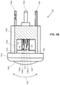
- FIG. 4B depicts a cutaway side view of a second embodiment of a removable spark head usable with embodiments of the present handheld probes, such as the one of FIG. 4 .
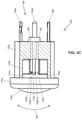
- FIG. 4C depicts a cutaway side view of a third embodiment of a removable spark head usable with embodiments of the present handheld probes, such as the one of FIG. 4 .
- FIGS. 5A-5B depict a timing diagrams of one example of the timed application of energy cycles or voltage pulses in the system of FIG. 3 and/or the handheld probe of FIG. 4 .
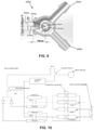
- FIG. 6 depicts a schematic diagram of one embodiment of a multi-gap pulse-generation system for use in or with some embodiments of the present systems.
- FIG. 7 depicts a block diagram of an embodiment of a radio-frequency (RF) powered acoustic ablation system.
- RF radio-frequency
- FIGS. 8A-8B depict perspective and cross-sectional views of a first embodiment of a spark chamber housing.
- FIG. 9 depicts a cross-sectional view of a second embodiment of spark chamber housing.
- FIG. 10 depicts a schematic diagram of an electric circuit for a pulse-generation system.
- FIG. 11 depicts an exploded perspective view of a further embodiment of the present probes having a spark head or module.
- FIGS. 12A and 12B depict parts of the assembly of the probe of FIG. 11 .
- FIGS. 13A and 13B depict perspective and side cross-sectional views, respectively, of the probe of FIG. 11 .
- FIG. 13C depicts an enlarged side cross-sectional view of a spark gap of the probe of FIG. 11 .
- FIG. 14 depicts a schematic diagram of a second embodiment of an electric circuit for a prototyped pulse-generation system.
- Embodiments of the present disclosure are directed to inducing inflammation in a tissue and particularly a tissue near the surface of the skin such as a subcutaneous adipose tissue, by applying a plurality of shockwaves to the tissue.
- the induced inflammation will lead to eventual apoptosis to a portion of the cells in the treated area.
- the shockwave treatments induce inflammation, the shockwaves are at a strength, frequency, and duration that are not likely to cause cavitation or thermal degradation in the treated tissue. As such, cell rupturing, would not be likely to occur. Rather, apoptosis would be caused by the inflammatory response of the body.
- sub-lytic injury occurs that induces inflammation. More particularly, the repeated high frequency, pressure wave energy applied to cells with lipid reserves can cause sub-lytic injury to the lipid containing vacuoles, triggering an inflammatory response.
- the ability to induce inflammation is dependent on four factors: (1) applied intensity (Pa), (2) the rate of wave pulses (Hz), (3) wave form shape (e.g., wave front rise time (ns) and wave length (ns)), or (4) duration of exposure.
- Pa applied intensity
- Hz the rate of wave pulses
- wave form shape e.g., wave front rise time (ns) and wave length (ns)
- duration of exposure e.g., wave front rise time (ns) and wave length (ns)
- One or more of these factors can be manipulated to cause a tissue with a high amount of stored lipids to have increased inflammation as compared to a non-treated area of similar character. The inflammation will eventually result in apoptosis and a reduction in the number of cells in the treated area.
- a possible theory to explain the phenomenon of the induced inflammations is the formation of lipid crystals in a sub-cellular structure.
- a series of pressure waves at a high frequency may induce nucleation of lipid crystals leading to the formation of crystals sufficiently large to cause injury to cellular organelles, such as a bilayer membrane.
- This injury initiates an inflammatory response that will eventually lead to apoptosis and necrosis.
- Nearby cells that are also exposed but not lipid rich like adipocyte cells, such as cells in the epidermis layer, are less likely to be damaged in the process.
- a method of treating a patient to reduce subcutaneous fat in a treatment area can comprise: directing a pressure wave generating probe (such as probe 38 or 38 a described below) to expose an external area of the patient to a series of pressure waves, where the pressure wave generating probe comprises a pressure wave outlet window, where the pressure wave generating probe is configured to generate at least 0.5 mJ per mm 2 or at least 2 mJ per mm 2 at the pressure wave outlet window.
- a pressure wave generating probe such as probe 38 or 38 a described below
- the pressure waves can have 0.5, 0.6, 0.8, 0.9, 1, 1.2, 1.4, 1.6, 1.8, 2, 2.2, 2.4, 2.6, 2.8, 3, 3.4, 3.8, 4, 4.4, 4.8, 5, 5.5, 6, 6.5, 7 mJ per mm 2 , or any value or range therebetween.
- the pressure wave generating probe is configured to generate or generates between 0.5 mJ per mm 2 to 5 mJ per mm 2 .
- the pressure wave outlet window has an area of 0.5 cm 2 to 20 cm 2 .
- the outlet window can have an area of at least 0.5, 0.8, 1, 2, 3, 4, 5, 6, 7. 8, 9, 10, 11, 12, 13, 14, 15, 16, 17, 18, 19, 20 cm 2 , or any value or range therebetween.
- the pressure waves are unfocused or substantially planar prior to entering into the treatment area of the patient.
- Other embodiments of the present methods comprise focusing the one or more pressure waves to a treatment area.
- the adipose tissue at which the one or more pressure waves is focused is the depth at which there is adipose tissue. Focusing the shockwaves may result in higher pressures at targeted cells than unfocused or planar waves.
- the treatment area is a portion of butt, thigh, stomach, waist, and/or upper arm area.
- the treatment area of subcutaneous fat is within a depth of 0-6 cm from the external area, such as 1, 2, 3, 4, 5, 6 cm, or any value or range therebetween. In some embodiments, the treatment area is at a depth of 1-4 cm.
- the pressure wave directed to the treatment area is a shockwave.
- FIG. 1 depicts a waveform of a shockwave that can be emitted from a probe and into a volume of tissue. The depicted form can be useful for inducing inflammation without causing cell rupturing.
- Pulse 300 is of a typical shape for an impulse generated by the described electrohydraulic (EH) spark heads described below. For example, pulse 300 has a rapid rise time (or wave front rise time), a short duration, and a ring down period.
- the units of vertical axis V a are arbitrary as may be displayed on an oscilloscope.
- the pressure wave generating probe can emit a shockwave comprising the following waveform characteristics in a transmitting medium.
- a transmitting medium can be a gas (e.g., air), a tissue (e.g., an adipose tissue) or an aqueous solution (e.g., a saline solution, such as one at 0.5-10% concentration).
- a shockwave emitted at the outlet window of the probe and/or delivered to the treatment area can have a shockwave front rise time of less than 20 ns, less than 18 ns, less than 15 ns, or less than 12 ns as measured in a transmitting medium.
- the actual acoustic pulse amplitude emitted may be 0.5 to 50 MPa.
- the individual time periods 304 may be 0.5 to 50 micro-seconds each in a transmitting medium.
- the probe emits a pressure wave at a pulse rate of at least 10 Hz.
- the probe emits a pressure wave at a pulse rate of between 10 Hz and 1000 Hz., such as 20, 30, 40, 50, 60, 70, 80 90, 100, 150, 200, 250, 300, 350, 400, 450, 500, 550, 600, 650, 700, 750, 800, 850, 900, 950, 1000 Hz, or any value or range therebetween.
- the probe emits a pressure wave at a pulse rate of between 10 Hz and 100 Hz. In some embodiments, the probe emits a pressure wave at a pulse rate of between 20 Hz and 75 Hz. In some embodiments, the probe emits a pressure wave at a pulse rate of between 100 Hz and 500 Hz. In some embodiments, the probe emits a pressure wave at a pulse rate of between 500 Hz and 1000 Hz. In some embodiments, the emitted waves are configured according to the characteristics above to induce minimal to no detectable transient cavitation in a transmitting medium.
- the method of treatment induces lipid crystallization, induces inflammation in the treated adipose tissue, reduces the amount of subcutaneous fat in the treatment area, and/or reduces the appearance of cellulite (e.g., resulting in a smoother appearance in the skin overlying the treatment area).
- subcutaneous fat comprises fat cells having intracellular fat and interstitial space between the fat cells.
- a reduction in the amount of fat e.g., a reduction in volume
- Example 2 describes a method for detecting a change in adipose tissue volume.
- the amount of fat is reduced about 1-14 days after one or more treatments, such as after 1, 2, 3, 4, 5, 6, 7, 8, 9, 10, 11, 12, 13, 14 days after the last treatment, or any value or range therebetween.
- an inflammation increase is indicated by an increase of one or more cytokines, such as one or more of leptin, IL-6, and TNF- ⁇ , in the patient's blood serum, or in the treatment area after treatment.
- an inflammation increase is indicated by an increase in inflammatory cells in the treatment area after treatment.
- the series of pressure waves would induce minimal to no adipose cell rupturing immediately after treatment, such as when treating an external treatment area of an animal model.
- Cell rupturing can be detected histologically, such as under 200 ⁇ to 1000 ⁇ magnification.
- inducing lipid crystallization is indicated by relatively higher tissue luminosity value under cross-polarized microscopy as compared with a control sample.
- Example 3 describes a method for detecting a comparable increase in lipid crystallization. Because of the recognized difficulty of performing such evaluations on a human patient, in some embodiments, the result of a treatment on a human can be estimated to correspond to the result of a treatment protocol on an animal model, such as a minipig.
- a treatment session can be 1 to 30 minutes within a 24 hour period.
- a treatment session can be 1, 2, 4, 5, 8, 10, 12, 15, 18, 20, 22, 24, 26, 28, 30 minutes or any value or within any range therebetween.
- a treatment session can be performed daily, every other day, every three days, weekly, bi-weekly, monthly, bi-monthly, and quarterly.
- a treatment plan can comprise 1 to 20 sessions within a one-year period, such as 1, 2, 3, 4, 5, 6, 7, 8, 9, 10, 11, 12, 13, 14, 15, 16, 17, 18, 19, 20 sessions or any value therebetween.
- a treatment plan comprises a session at least once per two weeks for at least 6 weeks.
- FIG. 2 illustrates one embodiment of a method 700 to direct shockwaves to target tissue.
- method 700 comprises a step 704 in which a treatment area 712 is identified.
- treatment area 712 can comprise skin affected with cellulite or having an unwanted accumulation of subcutaneous fat.
- method 700 also comprises a step 716 in which a probe or handpiece 38 is disposed toward treatment area 712 , such that shockwaves originating in probe 38 can be directed toward the adipose tissue in the treatment area.
- method 700 also comprises a step 720 in which a pulse-generation system 26 is coupled to probe 38 .
- method 700 also comprises a step 724 in which pulse-generation system 26 is activated to generate sparks across electrodes within probe 38 to generate shockwaves in probe 38 for delivery to adipose tissue underlying treatment area 712 , as shown.
- the above-described modalities may employ a shockwave generator.
- the generator can be configured to deliver focused, defocused, or planar waves with the above-described characteristics.
- EH waves are generated.
- the systems and apparatus described in U.S. Patent Publication No. 2014/0257144 can be configured to apply EH shockwaves at the described rate, energy level, and duration.
- the shockwave generating apparatus can be configured to generate a planar or defocused pressure wavefront.
- such a system can include a handheld probe (e.g., with a first housing, such as in FIG. 4 ) and a separate controller or pulse-generation system (e.g., in or with a second housing coupled to the handheld probe via a flexible cable or the like).
- a handheld probe e.g., with a first housing, such as in FIG. 4
- a separate controller or pulse-generation system e.g., in or with a second housing coupled to the handheld probe via a flexible cable or the like.
- apparatus 10 comprises: a housing 14 defining a chamber 18 and a shockwave outlet 20 ; a liquid ( 54 ) disposed in chamber 18 ; a plurality of electrodes (e.g., in spark head or module 22 ) configured to be disposed in the chamber to define one or more spark gaps; and a pulse-generation system 26 configured to apply voltage pulses to the electrodes at a rate of between 10 Hz and 1000 Hz, such as between 10 Hz and 100 Hz, 100 Hz and 500 Hz, or 500 Hz and 1000 Hz.
- the pulse-generation system 26 is configured to apply the voltage pulses to the electrodes such that portions of the liquid are vaporized to propagate shockwaves through the liquid and the shockwave outlet window.
- pulse-generation system 26 is configured for use with an alternating current power source (e.g., a wall plug).
- pulse-generation system 26 comprises a plug 30 configured to be inserted into a 110V wall plug.
- pulse-generation system 26 comprises a capacitive/inductive coil system, on example of which is described below with reference to FIG. 7 .
- pulse-generation system 26 is (e.g., removably) coupled to the electrodes in spark head or module 22 via a high-voltage cable 34 , which may, for example, include two or more electrical conductors and/or be heavily shielded with rubber or other type of electrically insulating material to prevent shock.
- high-voltage cable 34 is a combined tether or cable that further includes one or more (e.g., two) liquid lumens through which chamber 18 can be filled with liquid and/or via which liquid can be circulated through chamber 18 (e.g., via combined connection 36 ).
- apparatus 10 comprises a handheld probe or handpiece 38 and cable 34 is removably coupled to probe 38 via a high-voltage connector 42 , which is coupled to spark head or module 22 via two or more electrical conductors 44 .
- probe 38 comprises a head 46 and a handle 50
- probe 38 can comprise a polymer or other electrically insulating material to enable an operator to grasp handle 50 to position probe 38 during operation.
- handle 50 can be molded with plastic and/or can be coated with an electrically insulating material such as rubber.
- a liquid 54 (e.g., a dielectric liquid such as distilled water) is disposed in (e.g., and substantially fills) chamber 18 .
- spark head 22 is positioned in chamber 18 and surrounded by the liquid such that the electrodes can receive voltage pulses from pulse-generation system 26 (e.g., at a rate of between 10 Hz and 1000 Hz, 10 Hz and 100 Hz, 100 Hz and 500 Hz, or 500 Hz and 1000 Hz) such that portions of the liquid are vaporized to propagate shockwaves through the liquid and shockwave outlet 20 .
- probe 38 includes an acoustic delay chamber 58 between chamber 18 and outlet 20 .
- acoustic delay chamber is substantially filled with a liquid 62 (e.g., of the same type as liquid 54 ) and has a length 66 that is sufficient to permit shockwaves to form and/or be directed toward outlet 20 .
- length 66 may be between 2 millimeters (mm) and 25 millimeters (mm).
- chamber 18 and acoustic-delay chamber 58 are separated by a layer of sonolucent (acoustically permeable or transmissive) material that permits pressure waves or, more particularly, shockwaves to travel from chamber 18 into acoustic-delay chamber 58 .
- liquid 62 may be different than liquid 54 (e.g., liquid 62 may comprise bubbles, water, oil, mineral oil, and/or the like). Certain features such as bubbles may introduce and/or improve a nonlinearity in the acoustic behavior of liquid 54 to increase the formation of shockwaves.
- chamber 18 and acoustic-delay chamber 58 may be unitary (i.e., may comprise a single chamber).
- acoustic-delay chamber 58 may be replaced with a solid member (e.g., a solid cylinder of elastomeric material such as polyurethane).
- probe 38 further includes an outlet member 70 removably coupled to the housing at a distal end of the acoustic delay chamber, as shown.
- Member 70 is configured to contact an external area located above tissue 74 , and can be removed and either sterilized or replaced between patients.
- Member 70 comprises a polymer or other material (e.g., low-density polyethylene or silicone rubber) that is acoustically permeable to permit shockwaves to exit acoustic-delay chamber 58 via outlet 20 .
- an acoustic coupling gel may be disposed between member 70 and tissue 74 to lubricate and provide additional acoustic transmission into tissue 74 .
- probe 38 includes an acoustic mirror 78 that comprises a material (e.g., glass) and is configured to reflect a majority of sound waves and/or shockwaves that are incident on the acoustic mirror.
- acoustic mirror 78 can be angled to reflect sound waves and/or shockwaves (e.g., that originate at spark head 22 ) toward outlet 20 (via acoustic-delay chamber) in a defocused manner.
- housing 14 can comprise a translucent or transparent window 82 that is configured to permit a user to view (through window 82 , chamber 18 , chamber 58 , and member 70 ) a region of a patient (e.g., tissue 74 ) comprising target cells (e.g., during application of shockwaves or prior to application of shockwaves to position outlet 20 at the target tissue).
- window 82 comprises an acoustically reflective material (e.g., glass) that is configured to reflect a majority of sound waves and/or shockwaves that are incident on the window.
- window 82 can comprise clear glass of sufficient thickness and strength to withstand the high-energy acoustic pulses produced at spark head 22 (e.g., tempered plate glass having a thickness of about 2 mm and an optical transmission efficiency of greater than 50%).
- a human eye 86 indicates a user viewing the target tissue through window 82 , but it should be understood that target tissue may be “viewed” through window 82 via a camera (e.g., a digital still and/or video camera).
- a camera e.g., a digital still and/or video camera.
- acoustic energy can be positioned, applied, and repositioned according to target tissues, such as a region of cellulite, and by indications of acoustic energy, such as a change in the color of the tissue.
- FIG. 4 depicts a cross-sectional side view of a second embodiment 38 a of the present handheld probes or handpiece for use with some embodiments of the present EH shockwave generating systems and apparatuses.
- Probe 38 a is substantially similar in some respects to probe 38 , and the differences are therefore primarily described here.
- probe 38 a is also configured such that the plurality of electrodes of spark head 22 a are not visible to a user viewing a region (e.g., of target tissue) through window 82 a and outlet 20 a .
- probe 38 a is configured such that spark head 22 a (and the electrodes of the spark head) are offset from an optical path extending through window 82 a and outlet 20 a .
- acoustic mirror 78 a is positioned between spark head 22 a and outlet 20 a , as shown, to define a boundary of chamber 18 a and to direct acoustic waves and/or shockwaves from spark head 22 a to outlet 20 a .
- window 82 a can comprise a polymer or other acoustically permeable or transmissive material because acoustic mirror 78 a is disposed between window 82 a and chamber 18 a and sound waves and/or shockwaves are not directly incident on window 82 a (i.e., because the sound waves and/or shockwaves are primarily reflected by acoustic mirror 78 a ).
- spark head 22 a includes a plurality of electrodes 100 that define a plurality of spark gaps.
- the use of multiple spark gaps can be advantageous because it can double the number of pulses that can be delivered in a given period of time. For example, after a pulse vaporizes an amount of liquid in a spark gap the vapor must either return to its liquid state or must be displaced by a different portion of the liquid that is still in a liquid state.
- sparks also heat the electrodes. As such, for a given spark rate, increasing the number of spark gaps reduces the rate at which each spark gap must be fired and thereby extends the life of the electrodes. Thus, ten spark gaps potentially increases the possible pulse rate and/or electrode life by a factor of ten.
- probe 38 includes conduits 104 and 108 extending from chamber 18 a to respective connectors 112 and 116 , as shown.
- connectors 112 and 116 can be coupled to a pump to circulate liquid through chamber 18 a (e.g., and through a heat exchanger.
- pulse-generation system 26 FIG.
- a filter can be included in probe 38 a , in a spark generation system (e.g., 26 ), and/or between the probe and the spark generation system to filter liquid that is circulated through the chamber
- each shockwave to a target tissue includes a wave front 118 propagating from outlet 20 a and traveling outward through tissue 74 .
- wave front 118 is curved according to its expansion as it moves outwardly and partially according to the shape of the outer surface of outlet member 70 a that contacts tissue 74 .
- the outer shape of the contact member can be planar.
- FIG. 4A depicts an enlarged cross-sectional view of first embodiment of a removable spark head, shown as module 22 a .
- spark head 22 a comprises a sidewall 120 defining a spark chamber 124 , and a plurality of electrodes 100 a , 100 b , 100 c disposed in the spark chamber.
- spark chamber 124 is filled with liquid 128 which may be similar to liquid 54 ( FIG. 3 ).
- At least a portion of sidewall 120 comprises an acoustically permeable or transmitive material (e.g., a polymer such as polyethylene) configured to permit sound waves and/or shockwaves generated at the electrodes to travel through sidewall 120 and through chamber 18 a ( FIG. 4 ).
- acoustically permeable or transmitive material e.g., a polymer such as polyethylene
- spark head 22 a includes a cup-shaped member 132 that may be configured to be acoustically reflective and includes an acoustically permeable cap member 136 .
- cap member 136 is dome shaped to approximate the curved shape of an expanding wavefront that originates at the electrodes and to compress the skin when applied with moderate pressure.
- Cap member 136 can be coupled to cup-shaped member 132 with an O-ring or gasket 140 and a retaining collar 144 .
- cup-shaped member 132 has a cylindrical shape with a circular cross-section (e.g., with a diameter of 2 inches or less).
- cup-shaped member includes bayonet-style pins 148 , 152 configured to align with corresponding grooves in head 46 a of probe 38 a ( FIG. 4 ) to lock the position of spark head 22 a relative to the probe.
- an electrode core 156 having conductors 160 a , 160 b , 160 c and extending through aperture 164 , with the interface between aperture 164 and electrode core 156 sealed with a grommet 168 .
- a central conductor 160 a extends through the center of core 156 and serves as a ground to corresponding center electrode 100 a .
- Peripheral conductors 160 b , 160 c are in communication with peripheral electrodes 100 b , 100 c to generate sparks across the spark gap between electrodes 100 a and 100 b , and between electrodes 100 a and 100 c . It should be understood that while two spark gaps are shown, any number of spark gaps may be used, and may be limited only by the spacing and size of the spark gaps. For example, other embodiments include 3, 4, 5, 6, 7, 8, 9, 10, or even more spark gaps.
- FIG. 4B depicts an enlarged cutaway side view of a second embodiment of a removable spark head or module 22 b .
- spark head or module 22 b comprises a sidewall 120 a defining a spark chamber 124 a , and a plurality of electrodes 100 d - 1 , 100 d - 2 , 100 , 100 f disposed in the spark chamber.
- spark chamber 124 a is filled with liquid 128 a which may be similar to liquid 128 and/or 54 .
- spark head 22 b includes a cup-shaped member 132 a that may be configured to be acoustically reflective and an acoustically permeable cap member 136 a .
- cap member 136 a is dome shaped to approximate the curved shape of an expanding wavefront that originates at the electrodes and to compress the skin when applied with moderate pressure.
- Cap member 136 a can be coupled to cup-shaped member 132 a with an O-ring or gasket (not shown, but similar to 140 ) and a retaining collar 144 a .
- cup-shaped member 132 a has a cylindrical shape with a circular cross-section (e.g., with a diameter of 2 inches or less).
- cup-shaped member 132 a can also include bayonet-style pins (not shown, but similar to 148 , 152 ) configured to align with corresponding grooves in head 46 a of probe 38 a to lock the position of spark head 22 b relative to the probe.
- conductors 160 d , 160 e , 160 f extending through a rear portion (opposite outlet cap member 136 a ) of cup-shaped member 132 a , as shown.
- central conductor 160 d and peripheral conductors 160 e , 160 f can be molded into sidewall 120 a such that grommets and the like are not necessary to seal the interface between the sidewall and the conductors.
- a central conductor 160 d serves as a ground to corresponding center electrodes 100 d - 1 and 100 d - 2 , which are also in electrical communication with each other.
- Peripheral conductors 160 e , 160 f are in communication with peripheral electrodes 100 e , 100 f to generate sparks across the spark gap between electrodes 100 d - 1 and 100 e , and between electrodes 100 d - 2 and 100 f . It should be understood that while two spark gaps are shown, any number of spark gaps may be used, and may be limited only by the spacing and size of the spark gaps. For example, other embodiments include 3, 4, 5, 6, 7, 8, 9, 10, or even more spark gaps.
- central electrodes 100 d - 1 and 100 d - 2 are carried by, and may be unitary with, an elongated member 172 extending into chamber 124 a toward cap member 136 a from sidewall 120 a .
- member 172 is mounted to a hinge 176 (which is fixed relative to sidewall 120 a ) to permit the distal end of the member (adjacent electrodes 100 d - 1 , 100 d - 2 to pivot back and forth between electrodes 100 e and 100 f , as indicated by arrows 180 .
- the distal portion of member 172 is biased toward electrode 100 e by spring arms 184 .
- spring arms 184 are configured to position electrode 100 d - 1 at an initial spark gap distance from electrode 100 e .
- an electrical potential e.g., via a pulse-generation system, as described elsewhere in this disclosure
- a spark will arc between these two electrodes to release an electric pulse to vaporize liquid between these two electrodes.
- the expansion of vapor between these two electrodes drives member 172 and electrode 100 d - 2 downward toward electrode 100 f .
- the pulse-generation system can re-charge and apply an electric potential between electrodes 100 d - 2 and 100 f , such that when the distance between electrodes 100 d - 2 and 100 f becomes small enough, a spark will arc between these two electrodes to release the electric pulse to vaporize liquid between these two electrodes.
- the expansion of vapor between electrodes 100 d - 2 and 100 f then drives member 172 and electrode 100 d - 1 upward toward electrode 100 e .
- the pulse-generation system can re-charge and apply an electric potential between electrodes 100 d - 1 and 100 e , such that when the distance between electrodes 100 d - 1 and 100 e becomes small enough, a spark will arc between these two electrodes to release the electric pulse and vaporize liquid between these two electrodes, causing the cycle to begin again.
- member 172 oscillates between electrodes 100 e and 100 f until the electric potential ceases to be applied to the electrodes.
- the pivoting of member 172 and electrodes 100 d - 1 , 100 d - 2 between electrodes 100 e and 100 f effectively adjusts the spark gap for each spark.
- the distance between electrodes at which current arcs between the electrodes is a function of electrode material and electric potential.
- member 172 is configured to self-adjust the respective spark gaps between electrodes 100 d - 1 and 100 e , and between electrodes 100 d - 2 and 100 f.
- FIG. 4B Another example of an advantage of the present movable electrodes, as in FIG. 4B , is that multiple coils are not required as long as the electrodes are positioned such that only one pair of electrodes is within arcing distance at any given time, and such a single coil or coil system is configured to recharge in less time than it takes for member 172 to pivot from one electrode to the next.
- FIG. 4B Another example of an advantage of the present movable electrodes, as in FIG. 4B , is that multiple coils are not required as long as the electrodes are positioned such that only one pair of electrodes is within arcing distance at any given time, and such a single coil or coil system is configured to recharge in less time than it takes for member 172 to pivot from one electrode to the next.
- an electric potential may simultaneously be applied to electrodes 100 e and 100 f with electrodes 100 d - 1 and 100 d - 2 serving as a common ground, with the electric potential such that a spark will only arc between electrodes 100 d - 1 and 100 e when member 172 is pivoted upward relative to horizontal (in the orientation shown), and will only arc between electrodes 100 d - 2 and 100 f when member 172 is pivoted downward relative to horizontal.
- a single coil or coil system can be connected to both of peripheral electrodes 100 e , 100 f and alternately discharged through each of the peripheral electrodes.
- the pulse rate can be adjusted by selecting the physical properties of member 172 and spring arms 184 .
- the properties (e.g., mass, stiffness, cross-sectional shape and area, length, and/or the like) of member 172 and the properties (e.g., spring constant, shape, length, and/or the like) of spring arms 184 can be varied to adjust a resonant frequency of the system, and thereby the pulse rate of the spark head or module 22 b .
- the viscosity of liquid 128 a may be selected or adjusted (e.g., increased to reduce the speed of travel of arm 184 , or decreased to increase the speed of travel of arm 184 ).
- Another example of an advantage of the present movable electrodes, as in FIG. 4B is that properties (e.g., shape, cross-sectional area, depth, and the like) of the electrodes can be configured to achieve a known effective or useful life for the spark head (e.g., one 30-minute treatment) such that spark head 22 b is inoperative or of limited effectiveness after that designated useful life.
- a known effective or useful life for the spark head e.g., one 30-minute treatment
- spark head 22 b is inoperative or of limited effectiveness after that designated useful life.
- Such a feature can be useful to ensure that the spark head is disposed of after a single treatment, such as, for example, to ensure that a new, sterile spark head is used for each patient or area treated to minimize potential cross-contamination between patients or areas treated.
- FIG. 4C depicts an enlarged cutaway side view of a third embodiment of a removable spark head or module 22 c .
- Spark head 22 c is substantially similar to spark head 22 b , except as noted below, and similar reference numerals are therefore used to designate structures of spark head 22 c that are similar to corresponding structures of spark head 22 b .
- the primary difference relative to spark head 22 b is that spark head 22 c includes a beam 172 a that does not have a hinge, such that flexing of the beam itself provides the movement of electrodes 100 d - 1 and 100 d - 2 in the up and down directions indicated by arrows 180 , as described above for spark head 22 b .
- the resonant frequency of spark head 22 c is especially dependent on the physical properties (e.g., mass, stiffness, cross-sectional shape and area, length, and/or the like) of beam 172 a .
- beam 172 a is configured to be biased toward electrode 100 e , as shown, such that electrode 100 d - 1 is initially positioned at an initial spark gap distance from electrode 100 e .
- the function of spark head 22 c is similar to the function of spark head 22 b , with the exception that beam 172 a itself bends and provides some resistance to movement such that hinge 176 and spring arms 184 are unnecessary.
- spark head 22 b also includes liquid connectors or ports 188 , 192 via which liquid can be circulated through spark chamber 124 b .
- a proximal end 196 of spark head 22 b serves as a combined connection with two lumens for liquid (connectors or ports 188 , 192 ) and two or more (e.g., three, as shown) electrical conductors (connectors 160 d , 160 e , 160 f ).
- the combined connection of proximal end 196 can be coupled (directly or via a probe or handpiece) to a combined tether or cable having two liquid lumens (corresponding to connectors or ports 188 , 192 ), and two or more electrical conductors (e.g., a first electrical conductor for connecting to connector 160 d and a second electrical conductor for connecting to both peripheral connectors 160 e , 160 f ).
- a combined tether or cable can couple the spark head (e.g., and a probe or handpiece to which the spark head is coupled) to a pulse-generation system having a liquid reservoir and pump such that the pump can circulate liquid between the reservoir and the spark chamber.
- cap member 136 a is omitted such that connectors or ports 188 , 192 can permit liquid to be circulated through a larger chamber (e.g., 18 a ) of a handpiece to which the spark head is coupled.
- a probe or handpiece to which spark head 22 a is configured to be coupled can include electrical and liquid connectors corresponding to the respective electrical connectors ( 160 d , 160 e , 160 f ) and ports ( 188 , 192 ) of the spark head such that the electrical and liquid connectors of the spark head are simultaneously connected to the respective electrical and liquid connectors of the probe or handpiece as the spark module is coupled to the handpiece (e.g., via pressing the spark head and probe together and/or a twisting or rotating the spark head relative probe).
- a pulse rate of a few Hz to many KHz (e.g., up to 5 MHz) may be employed. Because the fatiguing event produced by a plurality of pulses, or shockwaves, is generally cumulative at higher pulse rates, treatment time may be significantly reduced by using many moderately-powered shockwaves in rapid succession rather than a few higher powered shockwaves spaced by long durations of rest. As noted above, at least some of the present embodiments (e.g., those with multiple spark gaps) enable electro-hydraulic generation of shockwaves at higher rates. For example, FIG.
- FIG. 5A depicts a timing diagram 200 enlarged to show two sequences of voltage pulses 204 , 208 applied to the electrodes of the present embodiments with a delay period 212 in between, and FIG. 5B depicts a timing diagram 216 showing a greater number of voltage pulses applied to the electrodes of the present embodiments.
- a portion of the respective sidewall ( 120 , 120 a , 120 b ) may be omitted such that the respective spark chamber ( 124 , 124 a , 124 b ) is also omitted or left open such that liquid in a larger chamber (e.g., 18 or 18 a ) of a corresponding handpiece can freely circulate between the electrodes.
- the spark chamber e.g., sidewall 120 , 120 a , 120 b can include liquid connectors or liquid may circulate through liquid ports that are independent of spark chamber (e.g., as depicted in FIG. 4 ).
- a series of events (sparks) initiated by a plurality of bursts or groups 204 and 208 delivered with the present systems and apparatuses can comprise a higher pulse rate (PR) that can reduce treatment time relative to lower PRs which may need to be applied over many minutes.
- PR pulse rate
- the embodiments can be used to deliver shockwaves at the desired pulse rate.
- FIG. 6 depicts a schematic diagram of one embodiment 400 of a pulse-generation system for use in or with some embodiments of the present systems.
- circuit 400 comprises a plurality of charge storage/discharge circuits each with a magnetic storage or induction type coil 404 a , 404 b , 404 c (e.g., similar to those used in automotive ignition systems).
- each of coils 404 a , 404 b , 404 c may be grounded via a resistor 408 a , 408 b , 408 c to limit the current permitted to flow through each coil, similar to certain aspects of automotive ignition systems.
- Resistors 408 a , 408 b , 408 c can each comprise dedicated resistors, or the length and properties of the coil itself may be selected to provide a desired level of resistance.
- circuit 400 includes a spark head 22 b that is similar to spark head 22 a with the exceptions that spark head 22 b includes three spark gaps 412 a , 412 b , 412 c instead of two, and that each of the three spark gaps is defined by a separate pair of electrodes rather than a common electrode (e.g., 100 a ) cooperating with multiple peripheral electrodes.
- each circuit may be coupled to peripheral electrodes 100 b , 100 c of spark head 22 a to generate sparks across the spark gaps defined with common electrode 22 a , as shown in FIG. 4A .
- each circuit is configured to function similarly.
- coil 404 a is configured to collect and store a current for a short duration such that, when the circuit is broken at switch 420 a , the magnetic field of the coil collapses and generates a so-called electromotive force, or EMF, that results in a rapid discharge of capacitor 424 a across spark gap 412 a.
- the RL or Resistor-Inductance time constant of coil 404 a which may be affected by factors such as the size and inductive reactance of the coil, the resistance of the coil windings, and other factors—generally corresponds to the time it takes to overcome the resistance of the wires of the coil and the time to build up the magnetic field of the coil, followed by a discharge which is controlled again by the time it takes for the magnetic field to collapse and the energy to be released through and overcome the resistance of the circuit.
- This RL time constant generally determines the maximum charge-discharge cycle rate of the coil. If the charge-discharge cycle is too fast, the available current in the coil may be too low and the resulting spark impulse weak.
- the use of multiple coils can overcome this limitation by firing multiple coils in rapid succession for each pulse group (e.g., 204 , 208 as illustrated in FIG. 5A ).
- two coils can double the practical charge-discharge rate by doubling the (combined) current and resulting spark impulse, and three (as shown) can effectively triple the effective charge-discharge rate.
- timing can be very important to proper generation of spark impulses and resulting liquid vaporization and shockwaves.
- a controller e.g., microcontroller, processer, FPGA, and/or the like
- a controller may be coupled to each of control points 428 a , 428 b , 428 c to control the timing of the opening of switches 420 a , 420 b , 420 c and resulting discharge of capacitors 424 a , 424 b , 424 c and generation of shockwaves.
- FIG. 7 depicts a block diagram of an embodiment 500 of a radio-frequency (RF) powered acoustic shockwave generation system.
- system 500 comprises a nonlinear medium 504 (e.g., as in acoustic-delay chamber 58 or nonlinear member described above) that provides an acoustic path to from a transducer 512 to target tissue 508 to produce practical harmonic or acoustic energy (e.g., shockwaves).
- transducer 512 is powered and controlled through bandpass filter and tuner 516 , RF power amplifier 520 , and control switch 524 .
- a typical driving waveform may comprise a sine wave burst (e.g., multiple sine waves in rapid succession).
- a typical burst may have a burst length of 10 milliseconds and comprise sine waves having a period duration of 0.1 (frequency of 100 MHz) to 100 microseconds (frequency of 10 Hz).
- FIGS. 8A-8B and 9 depict two different spark chamber housings.
- the embodiments of FIGS. 8A-8B depict one embodiment of a spark chamber housing.
- Housing 600 is similar in some respects to the portion of housing 14 a that defines head 46 a of probe 38 a ( FIG. 4 ).
- housing 600 includes fittings 604 , 608 to permit liquid to be circulated through spark chamber 612 .
- housing 600 includes electrode supports 616 and 620 through which electrodes 624 can be inserted to define a spark gap 628 (e.g., of 0.127 mm or 0.005 inches in the experiments described below).
- housing 600 has an elliptical inner surface shaped to reflect the shockwaves that initially travel backwards from the spark gap into the wall.
- supports 616 and 620 are not aligned with (rotated approximately 30 degrees around chamber 612 relative to) fittings 604 , 608 .
- housing 600 has a hemispherical shape and electrodes 624 are positioned such that an angle 632 between a central axis 636 through the center of shockwave outlet 640 and a perimeter 644 of chamber 612 is about 57 degrees.
- Other embodiments can be configured to limit this angular sweep and thereby direct the sound waves and/or shockwaves through a smaller outlet.
- FIG. 9 depicts a cross-sectional view of a second embodiment of a spark chamber housing.
- Housing 600 a is similar to housing 600 , with the exception that fittings 604 a , 608 a are rotated 90 degrees relative to support 620 a .
- Housing 600 a also differs in that chamber 612 a includes a hemispherical rear or proximal portion and a frusto-conical forward or distal portion.
- electrodes 624 a are positioned such that an angle 632 a between a central axis 636 a through the center of shockwave outlet 640 a and a perimeter 644 a of chamber 612 a is about 19 degrees.
- FIG. 10 depicts a schematic diagram of an electric circuit for a prototyped pulse-generation system used with the spark chamber housing of FIGS. 8A-8B .
- the schematic includes symbols known in the art, and is configured to achieve pulse-generation functionality similar to that described above.
- the depicted circuit is capable of operating in the relaxation discharge mode with embodiments of the present shockwave heads (e.g., 46 , 46 a , etc.).
- the circuit comprises a 110V alternating current (AC) power source, an on-off switch, a timer (“control block”), a step-up transformer that has a 3 kV or 3000V secondary voltage.
- the secondary AC voltage is rectified by a pair of high voltage rectifiers in full wave configuration.
- the capacitors discharge and become ready for recharge by the transformer and rectifiers.
- the discharge was about 30 Hz, regulated only by the natural rate of charge and discharge—hence the term “relaxation oscillation.”
- the discharge rate can be higher (e.g., as high as 100 Hz), such as for the multi-gap configuration of FIG. 6 .
- probe 38 b is similar in some respects to probes 38 and 38 a , and the differences are therefore primarily described here.
- probe 38 b comprises: a housing 14 b defining a chamber 18 b and a shockwave outlet 20 b ; a liquid disposed in chamber 18 b ; a plurality of electrodes (e.g., in spark head or module 22 d ) configured to be disposed in the chamber to define one or more spark gaps; and is configured to be coupled to a pulse-generation system (e.g., system 26 of FIG. 2 ) configured to apply voltage pulses to the electrodes at a rate of 10 Hz to 1000 Hz or at a rate of 10 Hz to 100 Hz.
- a pulse-generation system e.g., system 26 of FIG. 2
- spark head 22 d includes a housing 120 d and a plurality of electrodes 100 g that define a spark gap.
- probe 38 b is configured to permit liquid to be circulated through chamber 18 b via liquid connectors or ports 112 b and 116 b , one of which is coupled to spark head 22 d and the other of which is coupled to housing 14 b , as shown.
- housing 14 b is configured to receive spark head 22 d , as shown, such that housing 14 b and housing 120 d cooperate to define chamber 18 b (e.g., such that spark head 22 d and housing 14 b include a complementary parabolic surfaces that cooperate to define the chamber).
- housing 14 b and spark head 22 d includes acoustically-reflective liners 700 , 704 that cover their respective surfaces that cooperate to define chamber 18 b .
- housing 120 d of spark head 22 d includes a channel 188 b (e.g., along a central longitudinal axis of spark head 22 d ) extending between liquid connector 112 b and chamber 18 b and aligned with the spark gap between electrodes 100 g such that circulating water will flow in close proximity and/or through the spark gap.
- housing 14 b includes a channel 192 b extending between connection 116 b and chamber 18 b .
- housing 120 d includes a groove 708 configured to receive a resilient gasket or O-ring 140 a to seal the interface between spark head 22 d and housing 14 b
- housing 14 b includes a groove 712 configured to receive a resilient gasket or O-ring 140 b to seal the interface between housing 14 b and cap member 136 b when cap member 136 b is secured to housing 14 b by ring 716 and retaining collar 144 b.
- electrodes 100 g each includes a flat bar portion 724 and a perpendicular cylindrical portion 728 (e.g., comprising tungsten for durability) in electrical communication (e.g., unitary with) bar portion 724 such that cylindrical portion 728 can extend through a corresponding opening 732 in spark head 22 d into chamber 18 b , as shown.
- part of the sides of cylindrical portion 728 can be covered with an electrically insulative and/or resilient material (e.g., shrink wrap) such as, for example, to seal the interface between portion 728 and sidewall 120 b .
- sidewall 120 b also includes longitudinal grooves 733 configured to receive bar portions 724 of electrodes 100 g .
- housing 14 b also includes set screws 736 positioned to align with cylindrical portions 728 of electrodes 100 g when spark head 22 d is disposed in housing 14 b , such that set screws 736 can be tightened to press cylindrical portions 728 inward to adjust the spark gap between the cylindrical portions of electrodes 100 g .
- spark head 22 d is permanently adhered to housing 14 b ; however, in other embodiments, spark head 22 d may be removable from housing 14 b such as, for example, to permit replacement of electrodes 100 g individually or as part of a new or replacement spark head 22 d.
- FIG. 14 depicts a schematic diagram of another embodiment of an electric circuit for a pulse-generation system.
- the circuit of FIG. 14 is substantially similar to the circuit of FIG. 10 with the primary exception that the circuit of FIG. 14 includes an arrangement of triggered spark gaps instead of ionization switches, and includes certain components with different properties than corresponding components in the circuit of FIG. 10 (e.g., 200 k ⁇ resistors instead of 100 k ⁇ resistors).
- block “1” corresponds to a primary controller (e.g., processor) and block “2” corresponds to a voltage timer controller (e.g., oscillator), both of which may be combined in a single unit in some embodiments.
- a primary controller e.g., processor
- block “2” corresponds to a voltage timer controller (e.g., oscillator), both of which may be combined in a single unit in some embodiments.
- a Gottingen minipig ( ⁇ 30 Kg) was anesthetized.
- the mid-ventral sites were prepared by removing the skin hair here using hair clippers and then razor.
- High-frequency shockwaves were then applied to the two treatment sites.
- biopsies were taken of treatment sites using 3 mm circular punch biopsy instruments. Tissue samples were placed in buffered formalin for microscopic examination.
- the high frequency shockwave treatment protocols are shown in Table 1.
- the probe had a 30 mm diameter shockwave outlet window and was configured to generate electrohydraulic shockwaves. All five sites that were treated using different high frequency shockwave settings demonstrated inflammation in the subcutaneous fat. No evidence of cavitation or thermal damage was noted on any of the tissue in the slides.
- site 4.6 histological evaluations of site 4.6 were conducted on the day of treatment and 2 days post treatment. As noted in Table 1, Site 4.6 was treated using a high frequency shockwave treatment for 90 seconds at 9.2 J/p at a rate of 25 Hz. The adipose tissue demonstrated marked inflammatory cell infiltration two days post treatment indicating that inflammation had been induced. Furthermore, there was no evidence of cavitation, thermal damage or other tissue damage at the treatment site.
- a Gottingen minipig ( ⁇ 30 Kg) was prepared as described in Example 1. Two separate test sites (1.7, 1.8) were treated using high-frequency shockwaves (9.2j/p, 25 Hz, 240 seconds). The probe had a 30 mm diameter shockwave outlet window and was configured to generate electrohydraulic shockwaves.
- a Gottingen Minipig ( ⁇ 30 Kg) was prepared as described in Example 1. Site 1.8 after treatment described in Example 2 was measured immediately following the high frequency shockwave treatment. A biopsy was taken of the subcutaneous fat at the treated site. For comparison, a biopsy was taken at a non-treated site. Samples of the biopsied tissues were stored in saline and then prepared for cross-polarized light microscopic examination to see if evidence of crystal nucleation had occurred. To aid in visualizing crystal nucleation, tissue samples were cooled to allow crystal growth at the crystal nucleation sites.
Landscapes
- Health & Medical Sciences (AREA)
- Animal Behavior & Ethology (AREA)
- Veterinary Medicine (AREA)
- Public Health (AREA)
- General Health & Medical Sciences (AREA)
- Life Sciences & Earth Sciences (AREA)
- Rehabilitation Therapy (AREA)
- Physical Education & Sports Medicine (AREA)
- Pain & Pain Management (AREA)
- Epidemiology (AREA)
- Engineering & Computer Science (AREA)
- Biomedical Technology (AREA)
- Nuclear Medicine, Radiotherapy & Molecular Imaging (AREA)
- Radiology & Medical Imaging (AREA)
- Surgical Instruments (AREA)
- Micro-Organisms Or Cultivation Processes Thereof (AREA)
Abstract
Description
| Site | Total J | J/P | Hz | ||
| 4.6 | 20,700 | 9.2 | 25 | ||
| 4.7 | 41,400 | 9.2 | 25 | ||
| 4.8 | 20,700 | 6.9 | 33 | ||
| 4.9 | 41,400 | 6.9 | 33 | ||
| 4.10 | 20,700 | 4.6 | 50 | ||
Claims (25)
Priority Applications (1)
| Application Number | Priority Date | Filing Date | Title |
|---|---|---|---|
| US15/573,353 US11229575B2 (en) | 2015-05-12 | 2016-05-12 | Methods of treating cellulite and subcutaneous adipose tissue |
Applications Claiming Priority (4)
| Application Number | Priority Date | Filing Date | Title |
|---|---|---|---|
| US201562160147P | 2015-05-12 | 2015-05-12 | |
| US201662277796P | 2016-01-12 | 2016-01-12 | |
| US15/573,353 US11229575B2 (en) | 2015-05-12 | 2016-05-12 | Methods of treating cellulite and subcutaneous adipose tissue |
| US2016320069 | 2016-05-12 |
Related Parent Applications (1)
| Application Number | Title | Priority Date | Filing Date |
|---|---|---|---|
| PCT/US2016/032069 A-371-Of-International WO2016183307A1 (en) | 2015-05-12 | 2016-05-12 | Methods of treating cellulite and subcutaneous adipose tissue |
Related Child Applications (1)
| Application Number | Title | Priority Date | Filing Date |
|---|---|---|---|
| US17/648,790 Continuation US20220211573A1 (en) | 2015-05-12 | 2022-01-24 | Methods of treating cellulite and subcutaneous adipose tissue |
Publications (2)
| Publication Number | Publication Date |
|---|---|
| US20180116905A1 US20180116905A1 (en) | 2018-05-03 |
| US11229575B2 true US11229575B2 (en) | 2022-01-25 |
Family
ID=57249437
Family Applications (4)
| Application Number | Title | Priority Date | Filing Date |
|---|---|---|---|
| US15/573,353 Active 2038-07-12 US11229575B2 (en) | 2015-05-12 | 2016-05-12 | Methods of treating cellulite and subcutaneous adipose tissue |
| US17/648,790 Abandoned US20220211573A1 (en) | 2015-05-12 | 2022-01-24 | Methods of treating cellulite and subcutaneous adipose tissue |
| US18/373,265 Abandoned US20240156672A1 (en) | 2015-05-12 | 2023-09-26 | Methods of treating cellulite and subcutaneous adipose tissue |
| US18/917,971 Abandoned US20250177241A1 (en) | 2015-05-12 | 2024-10-16 | Methods of treating cellulite and subcutaneous adipose tissue |
Family Applications After (3)
| Application Number | Title | Priority Date | Filing Date |
|---|---|---|---|
| US17/648,790 Abandoned US20220211573A1 (en) | 2015-05-12 | 2022-01-24 | Methods of treating cellulite and subcutaneous adipose tissue |
| US18/373,265 Abandoned US20240156672A1 (en) | 2015-05-12 | 2023-09-26 | Methods of treating cellulite and subcutaneous adipose tissue |
| US18/917,971 Abandoned US20250177241A1 (en) | 2015-05-12 | 2024-10-16 | Methods of treating cellulite and subcutaneous adipose tissue |
Country Status (4)
| Country | Link |
|---|---|
| US (4) | US11229575B2 (en) |
| AU (3) | AU2016261936B2 (en) |
| CA (1) | CA2985811A1 (en) |
| WO (1) | WO2016183307A1 (en) |
Families Citing this family (29)
| Publication number | Priority date | Publication date | Assignee | Title |
|---|---|---|---|---|
| CN102781350B (en) | 2010-01-19 | 2016-09-14 | 得克萨斯大学体系董事会 | Device and system for generating high frequency shock waves and method of use |
| AR087170A1 (en) | 2011-07-15 | 2014-02-26 | Univ Texas | APPARATUS FOR GENERATING THERAPEUTIC SHOCK WAVES AND ITS APPLICATIONS |
| US10695575B1 (en) | 2016-05-10 | 2020-06-30 | Btl Medical Technologies S.R.O. | Aesthetic method of biological structure treatment by magnetic field |
| US20180001107A1 (en) | 2016-07-01 | 2018-01-04 | Btl Holdings Limited | Aesthetic method of biological structure treatment by magnetic field |
| US11484724B2 (en) | 2015-09-30 | 2022-11-01 | Btl Medical Solutions A.S. | Methods and devices for tissue treatment using mechanical stimulation and electromagnetic field |
| US12220380B2 (en) | 2015-09-30 | 2025-02-11 | Btl Medical Solutions A.S. | Methods and devices for tissue treatment using mechanical stimulation and electromagnetic field |
| EP3432985A4 (en) | 2016-03-23 | 2019-11-20 | Soliton, Inc. | SYSTEM AND METHOD FOR PULSED ACOUSTIC WAVE SKIN CLEANING |
| US11464993B2 (en) | 2016-05-03 | 2022-10-11 | Btl Healthcare Technologies A.S. | Device including RF source of energy and vacuum system |
| US11534619B2 (en) | 2016-05-10 | 2022-12-27 | Btl Medical Solutions A.S. | Aesthetic method of biological structure treatment by magnetic field |
| TWI742110B (en) | 2016-07-21 | 2021-10-11 | 美商席利通公司 | Rapid pulse electrohydraulic (eh) shockwave generator apparatus with improved electrode lifetime and method of producing compressed acoustic wave using same |
| US11141219B1 (en) | 2016-08-16 | 2021-10-12 | BTL Healthcare Technologies, a.s. | Self-operating belt |
| KR102583380B1 (en) | 2017-01-17 | 2023-10-04 | 솔리톤, 인코포레이티드 | Fast pulse electrohydraulic (EH) shock wave generator device with improved acoustic wavefront |
| AU2018221251B2 (en) | 2017-02-19 | 2023-04-06 | Soliton, Inc. | Selective laser induced optical breakdown in biological medium |
| US10751246B2 (en) | 2017-12-26 | 2020-08-25 | Sanjeev Kaila | Acoustic shock wave therapeutic methods |
| US11980388B2 (en) | 2018-07-23 | 2024-05-14 | Revelle Aesthetics, Inc. | Cellulite treatment apparatus |
| WO2020023406A1 (en) | 2018-07-23 | 2020-01-30 | Nc8, Inc. | Cellulite treatment system and methods |
| MX2021000902A (en) | 2018-07-23 | 2021-08-24 | Revelle Aesthetics Inc | Cellulite treatment system and methods. |
| CA3135847A1 (en) * | 2019-04-03 | 2020-10-08 | Soliton, Inc. | Systems, devices, and methods of treating tissue and cellulite by non-invasive acoustic subcision |
| EP3952984B1 (en) | 2019-04-11 | 2024-09-04 | BTL Medical Solutions a.s. | Devices for aesthetic treatment of biological structures by radiofrequency and magnetic energy |
| US12156689B2 (en) | 2019-04-11 | 2024-12-03 | Btl Medical Solutions A.S. | Methods and devices for aesthetic treatment of biological structures by radiofrequency and magnetic energy |
| US12558146B2 (en) | 2019-04-11 | 2026-02-24 | Btl Medical Solutions A.S. | Methods and devices for aesthetic treatment of biological structures by radiofrequency and magnetic energy |
| CA3153485A1 (en) | 2019-09-06 | 2021-03-11 | Revelle Aesthetics, Inc. | Cellulite treatment system and methods |
| JP2023515722A (en) | 2020-05-04 | 2023-04-13 | ビーティーエル ヘルスケア テクノロジーズ エー.エス. | Devices and methods for unattended care of patients |
| US12611545B2 (en) | 2020-05-04 | 2026-04-28 | Btl Healthcare Technologies A.S. | Device and method for unattended treatment of a patient |
| US11878167B2 (en) | 2020-05-04 | 2024-01-23 | Btl Healthcare Technologies A.S. | Device and method for unattended treatment of a patient |
| CA3260012A1 (en) | 2021-10-13 | 2023-04-20 | Btl Medical Solutions A.S. | Devices for aesthetic treatment of biological structures by radiofrequency and magnetic energy |
| US11896816B2 (en) | 2021-11-03 | 2024-02-13 | Btl Healthcare Technologies A.S. | Device and method for unattended treatment of a patient |
| US20240122794A1 (en) * | 2022-10-12 | 2024-04-18 | Softwave Tissue Regeneration Technologies, Inc. | Acoustic shock wave or pressure pulse treatment and methods of use for anti-aging |
| US20260097226A1 (en) | 2024-10-08 | 2026-04-09 | Btl Medical Solutions A.S. | Devices and methods for application of a magnetic field to the nervous system |
Citations (196)
| Publication number | Priority date | Publication date | Assignee | Title |
|---|---|---|---|---|
| US3364708A (en) | 1956-01-12 | 1968-01-23 | Rohr Corp | Electrical discharge method of and apparatus for generating shock waves in water |
| US3604641A (en) | 1969-02-10 | 1971-09-14 | Atomic Energy Authority Uk | Apparatus for hydraulic crushing |
| US3613069A (en) | 1969-09-22 | 1971-10-12 | Gen Dynamics Corp | Sonar system |
| US3735764A (en) | 1970-11-23 | 1973-05-29 | O Balev | Instrument for crushing stones in urinary bladder |
| US3769963A (en) | 1972-03-31 | 1973-11-06 | L Goldman | Instrument for performing laser micro-surgery and diagnostic transillumination of living human tissue |
| US3942531A (en) | 1973-10-12 | 1976-03-09 | Dornier System Gmbh | Apparatus for breaking-up, without contact, concrements present in the body of a living being |
| US4005314A (en) | 1975-07-11 | 1977-01-25 | The United States Of America As Represented By The Secretary Of The Army | Short pulse generator |
| EP0008647A1 (en) | 1978-07-22 | 1980-03-19 | DORNIER SYSTEM GmbH | Apparatus for the reattachment of a detached retina of the eye |
| US4311147A (en) | 1979-05-26 | 1982-01-19 | Richard Wolf Gmbh | Apparatus for contact-free disintegration of kidney stones or other calculi |
| DE3150430C1 (en) | 1981-12-19 | 1983-07-28 | Dornier System Gmbh, 7990 Friedrichshafen | Circuit for generating an underwater discharge |
| JPS61293447A (en) | 1985-06-21 | 1986-12-24 | オリンパス光学工業株式会社 | Apparatus for crushing stone by impact wave |
| JPS62192150A (en) | 1986-02-19 | 1987-08-22 | シ−メンス、アクチエンゲゼルシヤフト | Couplers for shock wave therapy devices |
| EP0243650A1 (en) | 1986-04-01 | 1987-11-04 | Siemens Aktiengesellschaft | Shockwave generator with an improved focus zone |
| US4715376A (en) | 1986-11-07 | 1987-12-29 | Trutek Research, Inc. | Isolation of gas in hydraulic spark gap shock wave generator |
| FR2605874A1 (en) | 1986-10-29 | 1988-05-06 | Univ Karlova | DEVICE FOR THE CLINICAL EXECUTION OF EXTRA-BODILY LITHOTRIPSY |
| JPS63183050A (en) | 1987-01-24 | 1988-07-28 | ドルニエ、メディツィンテヒニク、ゲゼルシャフト、ミット、ベシュレンクテル、ハフツング | Apparatus for non-contact crushing of stone in living body |
| DE3710371A1 (en) | 1987-03-28 | 1988-10-13 | Dornier Medizintechnik | DESTRUCTION OF DISEASED TISSUE CELLS |
| EP0322473A1 (en) | 1987-12-28 | 1989-07-05 | Northgate Research, Inc. a corporation of the state of Illinois | Degassification of water in hydraulic spark gap shock wave generator |
| EP0326620A1 (en) | 1987-12-28 | 1989-08-09 | Northgate Research, Inc. a corporation of the state of Illinois | Isolation of gas in hydraulic spark gap shock wave generator |
| US4858597A (en) | 1983-06-01 | 1989-08-22 | Richard Wolf Gmbh | Piezoelectric transducer for the destruction of concretions within an animal body |
| US4896673A (en) | 1988-07-15 | 1990-01-30 | Medstone International, Inc. | Method and apparatus for stone localization using ultrasound imaging |
| US4905671A (en) | 1988-01-11 | 1990-03-06 | Dornier Medizintechnik Gmbh | Inducement of bone growth by acoustic shock waves |
| US4962752A (en) | 1986-02-19 | 1990-10-16 | Siemens Aktiengesellschaft | Coupling member for a shock wave therapy device |
| US4979501A (en) | 1987-05-19 | 1990-12-25 | Vissh Voennomedicinski Institut | Method and apparatus for medical treatment of the pathological state of bones |
| US5009232A (en) | 1988-08-17 | 1991-04-23 | Siemens Aktiengesellschaft | Extracorporeal lithotripsy apparatus using high intensity shock waves for calculus disintegration and low intensity shock waves for imaging |
| US5015929A (en) | 1987-09-07 | 1991-05-14 | Technomed International, S.A. | Piezoelectric device with reduced negative waves, and use of said device for extracorporeal lithotrity or for destroying particular tissues |
| WO1991010227A1 (en) | 1990-01-04 | 1991-07-11 | Technomed International | Electrical discharge device for a reduced inductance liquid medium |
| US5149406A (en) | 1989-08-03 | 1992-09-22 | Hughes Aircraft Company | Electrical field quenching of optical breakdown |
| US5150713A (en) | 1989-08-21 | 1992-09-29 | Kabushiki Kaisha Toshiba | Method and system for controlling shock wave irradiation in a shock wave therapy apparatus |
| US5193527A (en) | 1989-10-03 | 1993-03-16 | Richard Wolf Gmbh | Ultrasonic shock-wave transducer |
| US5195508A (en) | 1990-05-18 | 1993-03-23 | Dornier Medizintechnik Gmbh | Spark gap unit for lithotripsy |
| US5204820A (en) | 1987-03-11 | 1993-04-20 | Eastman Kodak Company | Method of producing an optically effective arrangement in particular for application with a vehicular headlight |
| US5231976A (en) | 1989-03-21 | 1993-08-03 | Hans Wiksell | Apparatus for triggering shock waves |
| US5240005A (en) | 1990-11-22 | 1993-08-31 | Dornier Medizintechnik Gmbh | Acoustic focussing device |
| US5245988A (en) | 1989-11-15 | 1993-09-21 | Dormer Gmbh | Preparing a circuit for the production of shockwaves |
| US5259368A (en) | 1989-03-21 | 1993-11-09 | Hans Wiksell | Apparatus for comminuting concretions in the body of a patient |
| JPH067365A (en) | 1992-04-24 | 1994-01-18 | Siemens Ag | Device for medical treatment by means of focusing sound wave |
| US5284143A (en) | 1991-06-13 | 1994-02-08 | Siemens Aktiengesellschaft | Apparatus for treating bone pathologies with acoustic energy |
| US5304170A (en) | 1993-03-12 | 1994-04-19 | Green Howard A | Method of laser-induced tissue necrosis in carotenoid-containing skin structures |
| US5304207A (en) | 1992-02-05 | 1994-04-19 | Merrill Stromer | Electrostimulator with light emitting device |
| JPH06505648A (en) | 1990-12-26 | 1994-06-30 | テクノメッド メディカル システムズ | Method and device for interposing liquid between electrodes of shock wave device |
| US5327890A (en) | 1991-09-16 | 1994-07-12 | Siemens Aktiengesellschaft | Apparatus for treating a patient with acoustic waves |
| US5360447A (en) | 1993-02-03 | 1994-11-01 | Coherent, Inc. | Laser assisted hair transplant method |
| US5374236A (en) | 1991-03-27 | 1994-12-20 | Siemens Aktiengesellschaft | Electromagnetic pressure pulse source |
| US5393296A (en) | 1992-12-09 | 1995-02-28 | Siemens Aktiengesellschaft | Method for the medical treatment of pathologic bone |
| US5409446A (en) | 1991-06-06 | 1995-04-25 | Siemens Aktiengesellschaft | Coupling device for introducing acoustic waves into the body of a life form |
| US5419327A (en) | 1992-12-07 | 1995-05-30 | Siemens Aktiengesellschaft | Acoustic therapy means |
| US5423803A (en) | 1991-10-29 | 1995-06-13 | Thermotrex Corporation | Skin surface peeling process using laser |
| US5458652A (en) | 1992-09-28 | 1995-10-17 | Hmt High Medical Technologies Entwicklungs-Und Vertriebs Ag | Device for generating shock waves for non contact disintegration of calculi |
| US5509200A (en) | 1994-11-21 | 1996-04-23 | International Business Machines Corporation | Method of making laminar stackable circuit board structure |
| JPH08140984A (en) | 1994-09-19 | 1996-06-04 | Toshiba Corp | Ultrasonic therapy equipment |
| US5529572A (en) | 1992-01-24 | 1996-06-25 | Medispec Ltd. | Method and apparatus particularly useful for treating osteoporosis |
| JPH08194079A (en) | 1995-01-13 | 1996-07-30 | Toshiba Tungaloy Co Ltd | Heat generating apparatus utilizing reaction phenomenon of alloy containing deuterium in dynamic ultrasonic field |
| US5595178A (en) | 1994-10-02 | 1997-01-21 | Hmt High Medical Technologies Gmbh | System, method and apparatus for treatment of degenerative bone |
| US5618275A (en) | 1995-10-27 | 1997-04-08 | Sonex International Corporation | Ultrasonic method and apparatus for cosmetic and dermatological applications |
| JPH09103434A (en) | 1995-03-31 | 1997-04-22 | Toshiba Corp | Ultrasound therapy equipment |
| US5658239A (en) | 1992-05-12 | 1997-08-19 | Delmenico; Peter R. | Method and apparatus to establish target coordinates for lithotripsy |
| US5675495A (en) | 1995-05-18 | 1997-10-07 | Hella K.G. Hueck & Co. | Process for the design of free form reflectors which accounts for manufacturing tolerances |
| US5676159A (en) | 1996-11-05 | 1997-10-14 | Janin Group | Ultrasound cover |
| US5709676A (en) | 1990-02-14 | 1998-01-20 | Alt; Eckhard | Synergistic treatment of stenosed blood vessels using shock waves and dissolving medication |
| US5722411A (en) | 1993-03-12 | 1998-03-03 | Kabushiki Kaisha Toshiba | Ultrasound medical treatment apparatus with reduction of noise due to treatment ultrasound irradiation at ultrasound imaging device |
| JPH10192289A (en) | 1997-01-13 | 1998-07-28 | Olympus Optical Co Ltd | Apparatus for ultrasonic therapy |
| US5790305A (en) | 1995-04-13 | 1998-08-04 | Thomson Multimedia S.A. | Projection system comprising a free form reflector and a free form lens |
| US5827204A (en) | 1996-11-26 | 1998-10-27 | Grandia; Willem | Medical noninvasive operations using focused modulated high power ultrasound |
| RU2121812C1 (en) | 1995-06-14 | 1998-11-20 | Панин Михаил Георгиевич | Device for forming acoustic waves for lithotriptor |
| JPH10328192A (en) | 1997-05-30 | 1998-12-15 | Suzuki Motor Corp | Discharge electrode of shock wave therapy device |
| US6013122A (en) | 1998-08-18 | 2000-01-11 | Option Technologies, Inc. | Tattoo inks |
| US6036661A (en) | 1997-05-02 | 2000-03-14 | Hmt Holding Ag | Apparatus for administering acoustic shock waves |
| US6039694A (en) | 1998-06-25 | 2000-03-21 | Sonotech, Inc. | Coupling sheath for ultrasound transducers |
| US6058932A (en) | 1997-04-21 | 2000-05-09 | Hughes; Arthur R. | Acoustic transceiver respiratory therapy apparatus |
| US6080119A (en) | 1997-05-02 | 2000-06-27 | Hmt Holding Ag | Process and device for generating shock waves for medical uses |
| RU2151559C1 (en) | 1997-08-05 | 2000-06-27 | Акционерное общество закрытого типа Научно-производственный медицинский центр "РУМЕЛИТ" | Device for stimulating tissue metabolism with shock wave impulses |
| US6096029A (en) | 1997-02-24 | 2000-08-01 | Laser Skin Toner, Inc. | Laser method for subsurface cutaneous treatment |
| US6113559A (en) | 1997-12-29 | 2000-09-05 | Klopotek; Peter J. | Method and apparatus for therapeutic treatment of skin with ultrasound |
| US6113560A (en) | 1994-09-21 | 2000-09-05 | Hmt High Medical Techologies | Method and device for generating shock waves for medical therapy, particularly for electro-hydraulic lithotripsy |
| US6176839B1 (en) | 1997-08-04 | 2001-01-23 | Hmt High Medical Technologies Ag | Method and system for treatment with acoustic shock waves |
| US6186963B1 (en) | 1997-05-02 | 2001-02-13 | Hmt Holding Ag | Device for generating acoustic shock waves, especially for medical applications |
| US6210329B1 (en) | 1999-08-09 | 2001-04-03 | Docsystems, Inc. | Apparatus for organizing, transporting, and facilitating the use of obstetrical and other medical devices and supplies |
| US6309355B1 (en) | 1998-12-22 | 2001-10-30 | The Regents Of The University Of Michigan | Method and assembly for performing ultrasound surgery using cavitation |
| US6325769B1 (en) | 1998-12-29 | 2001-12-04 | Collapeutics, Llc | Method and apparatus for therapeutic treatment of skin |
| US20020009015A1 (en) | 1998-10-28 | 2002-01-24 | Laugharn James A. | Method and apparatus for acoustically controlling liquid solutions in microfluidic devices |
| US6350245B1 (en) | 1998-12-22 | 2002-02-26 | William W. Cimino | Transdermal ultrasonic device and method |
| US6368929B1 (en) | 2000-08-17 | 2002-04-09 | Motorola, Inc. | Method of manufacturing a semiconductor component and semiconductor component thereof |
| WO2002030256A2 (en) | 2000-10-13 | 2002-04-18 | Monash University | Diagnostic indicator of thymic function |
| US6390995B1 (en) | 1997-02-12 | 2002-05-21 | Healthtronics Surgical Services, Inc. | Method for using acoustic shock waves in the treatment of medical conditions |
| US6450979B1 (en) | 1998-02-05 | 2002-09-17 | Miwa Science Laboratory Inc. | Ultrasonic wave irradiation apparatus |
| US6454713B1 (en) | 1995-03-31 | 2002-09-24 | Kabushiki Kaisha Toshiba | Ultrasound therapeutic apparatus |
| US6487447B1 (en) | 2000-10-17 | 2002-11-26 | Ultra-Sonic Technologies, L.L.C. | Method and apparatus for in-vivo transdermal and/or intradermal delivery of drugs by sonoporation |
| US6491685B2 (en) | 1999-03-04 | 2002-12-10 | The Regents Of The University Of California | Laser and acoustic lens for lithotripsy |
| US20020193831A1 (en) | 2001-04-26 | 2002-12-19 | Smith Edward Dewey | Method and apparatus for the treatment of cosmetic skin conditions |
| US6515842B1 (en) | 2000-03-30 | 2003-02-04 | Avx Corporation | Multiple array and method of making a multiple array |
| US6519376B2 (en) | 2000-08-02 | 2003-02-11 | Actis S.R.L. | Opto-acoustic generator of ultrasound waves from laser energy supplied via optical fiber |
| US6551308B1 (en) | 1997-09-17 | 2003-04-22 | Laser-Und Medizin-Technologie Gmbh Berlin | Laser therapy assembly for muscular tissue revascularization |
| US20030167964A1 (en) | 1998-11-20 | 2003-09-11 | Freedom-2, Inc. | Permanent, removable tissue markings |
| US20030233045A1 (en) | 2002-05-30 | 2003-12-18 | University Of Washington | Solid hydrogel coupling for ultrasound imaging and therapy |
| US6666834B2 (en) | 2001-01-11 | 2003-12-23 | Hmt High Medical Technologies Ag | Method and apparatus for generating shock waves |
| US20040006288A1 (en) | 2000-10-29 | 2004-01-08 | Avner Spector | Pressure-pulse therapy device for treatment of deposits |
| US6755821B1 (en) | 1998-12-08 | 2004-06-29 | Cardiocavitational Systems, Inc. | System and method for stimulation and/or enhancement of myocardial angiogenesis |
| US20040181219A1 (en) | 2000-02-08 | 2004-09-16 | Gyrus Medical Limited | Electrosurgical instrument and an electrosugery system including such an instrument |
| DE60008898T2 (en) | 1999-10-01 | 2005-01-05 | Internova International Innovation Co. B.V. | lithotrity |
| US20050015023A1 (en) | 2003-07-17 | 2005-01-20 | Moshe Ein-Gal | Shockwave generating system |
| US6905467B2 (en) | 1997-08-15 | 2005-06-14 | Acuson Corporation | Ultrasonic harmonic imaging system and method using waveform pre-distortion |
| US20050150830A1 (en) | 1998-10-28 | 2005-07-14 | Covaris, Inc. | Systems and methods for determining a state of fluidization and/or a state of mixing |
| US6942663B2 (en) | 2002-03-12 | 2005-09-13 | Board Of Regents, The University Of Texas System | Laser treatment of cutaneous vascular lesions |
| US6972116B2 (en) | 2001-03-15 | 2005-12-06 | Hmt Holding Ag | Device for producing electrical discharges in an aqueous medium |
| US20060036168A1 (en) | 2004-07-22 | 2006-02-16 | Shen-Min Liang | Electrohydraulic shock wave-generating system with automatic gap adjustment |
| US20060064082A1 (en) | 2004-09-20 | 2006-03-23 | Bonutti Peter M | Minimally invasive therapeutic system |
| US20060100550A1 (en) | 2004-10-22 | 2006-05-11 | Reiner Schultheiss | Pressure pulse/shock wave therapy methods and an apparatus for conducting the therapeutic methods |
| US20060158956A1 (en) | 1998-10-28 | 2006-07-20 | Covaris, Inc. | Methods and systems for modulating acoustic energy delivery |
| US20060173388A1 (en) | 2002-07-30 | 2006-08-03 | Siegfried Ginter | Method for effecting local increases in temperature inside materials, particularly body tissue |
| US20060184071A1 (en) | 1997-12-29 | 2006-08-17 | Julia Therapeutics, Llc | Treatment of skin with acoustic energy |
| US20060200116A1 (en) | 2005-03-04 | 2006-09-07 | Searete Llc, A Limited Liability Corporation Of The State Of Delaware | Method and system for temporary hair removal |
| JP2007000218A (en) | 2005-06-22 | 2007-01-11 | Hitachi Medical Corp | Ultrasonic therapy apparatus |
| US20070016112A1 (en) | 2005-06-09 | 2007-01-18 | Reiner Schultheiss | Shock Wave Treatment Device and Method of Use |
| US20070038060A1 (en) | 2005-06-09 | 2007-02-15 | Cerwin Stephen A | Identifying and treating bodily tissues using electromagnetically induced, time-reversed, acoustic signals |
| US20070049829A1 (en) | 2005-07-20 | 2007-03-01 | Ust, Inc. | Thermally enhanced piezoelectric element |
| US20070055180A1 (en) | 2005-09-07 | 2007-03-08 | Mark Deem | System for treating subcutaneous tissues |
| US7189209B1 (en) | 1996-03-29 | 2007-03-13 | Sanuwave, Inc. | Method for using acoustic shock waves in the treatment of a diabetic foot ulcer or a pressure sore |
| US20070065420A1 (en) | 2005-08-23 | 2007-03-22 | Johnson Lanny L | Ultrasound Therapy Resulting in Bone Marrow Rejuvenation |
| US7250047B2 (en) | 2002-08-16 | 2007-07-31 | Lumenis Ltd. | System and method for treating tissue |
| WO2007088546A2 (en) | 2006-02-02 | 2007-08-09 | Releaf Medical Ltd. | Shock-wave generating device, such as for the treatment of calcific aortic stenosis |
| CN101028525A (en) | 2006-09-01 | 2007-09-05 | 上海美恩生物技术有限公司 | Use of tumor cell nuclear monoclonal antibody as a synergist in physical therapy of solid tumors |
| US20070219760A1 (en) | 2006-03-17 | 2007-09-20 | Tsinghua University | System and method for designing a free form reflector |
| US20070239082A1 (en) | 2006-01-27 | 2007-10-11 | General Patent, Llc | Shock Wave Treatment Device |
| US20070239084A1 (en) | 2006-01-18 | 2007-10-11 | Axel Voss | Device for generating shock waves |
| US20070239072A1 (en) | 2004-10-22 | 2007-10-11 | Reiner Schultheiss | Treatment or pre-treatment for radiation/chemical exposure |
| US20070249939A1 (en) | 2006-04-20 | 2007-10-25 | Gynesonics, Inc. | Rigid delivery systems having inclined ultrasound and curved needle |
| WO2007146988A1 (en) | 2006-06-15 | 2007-12-21 | University Of Pittsburgh - Of The Commonwealth System Of Higher Education | Methods of diminishing permanent tissue markings and related apparatus |
| US7311678B2 (en) | 1999-02-07 | 2007-12-25 | Medispec Ltd. | Pressure-pulse therapy apparatus |
| US20080009885A1 (en) | 2006-06-07 | 2008-01-10 | Antonio Del Giglio | Skin and adipose tissue treatment by nonfocalized opposing side shock waves |
| TWI292341B (en) | 2005-08-30 | 2008-01-11 | Univ Nat Sun Yat Sen | An atomizer with mems-based spray device |
| US20080021447A1 (en) | 1998-08-11 | 2008-01-24 | Arthrocare Corporation | Instrument for electrosurgical tissue treatment |
| CN101146574A (en) | 2005-02-06 | 2008-03-19 | 超形态公司 | Non-thermal sonic tissue changes |
| CN101155614A (en) | 2005-03-15 | 2008-04-02 | 西纳龙医药有限公司 | Method and apparatus for soft tissue treatment |
| US7364554B2 (en) | 2001-05-23 | 2008-04-29 | Sanuwave, Inc. | Apparatus for administering acoustic shock waves having a removable and replaceable component with a data storage medium |
| WO2008052198A2 (en) | 2006-10-26 | 2008-05-02 | Reliant Technologies, Inc. | Methods of increasing skin permeability by treatment with electromagnetic radiation |
| US20080107744A1 (en) | 2006-11-06 | 2008-05-08 | Jack Fa-De Chu | Injectable hollow tissue filler |
| US20080132810A1 (en) | 2006-11-30 | 2008-06-05 | Scoseria Jose P | Multiple lithotripter electrode |
| WO2008074005A1 (en) | 2006-12-13 | 2008-06-19 | Palomar Medical Technologies, Inc. | Cosmetic and biomedical applications of ultrasonic energy and methods of generation thereof |
| US20080146971A1 (en) | 2004-02-19 | 2008-06-19 | General Patent Llc | Pressure pulse/shock wave apparatus for generating waves having plane, nearly plane, convergent off target or divergent characteristics |
| US20080183200A1 (en) | 2006-06-07 | 2008-07-31 | Bacoustics Llc | Method of selective and contained ultrasound debridement |
| US20080195003A1 (en) | 2007-02-08 | 2008-08-14 | Sliwa John W | High intensity focused ultrasound transducer with acoustic lens |
| US20080194967A1 (en) | 2007-02-08 | 2008-08-14 | Sliwa John W | High intensity focused ultrasound transducer with acoustic lens |
| US20080262483A1 (en) | 2007-04-17 | 2008-10-23 | University Of Pittsburgh-Of The Commonwealth System Of Higher Education | Method for removing permanent tissue markings |
| US20080269163A1 (en) | 2004-10-19 | 2008-10-30 | Sostaric Joe Z | Methods and Compositions for Protecting Cells from Ultrasound-Mediated Cytolysis |
| US20080269608A1 (en) | 2005-10-20 | 2008-10-30 | The General Hospital Corporation D/B/A Massachusetts General Hospital | Non-Invasive Treatment of Fascia |
| WO2008137942A1 (en) | 2007-05-07 | 2008-11-13 | Guided Therapy Systems, Llc. | Methods and systems for modulating medicants using acoustic energy |
| US20080319356A1 (en) | 2005-09-22 | 2008-12-25 | Cain Charles A | Pulsed cavitational ultrasound therapy |
| US20090018472A1 (en) | 2007-01-08 | 2009-01-15 | Azita Soltani | Power parameters for ultrasonic catheter |
| US7507213B2 (en) | 2004-03-16 | 2009-03-24 | General Patent Llc | Pressure pulse/shock wave therapy methods for organs |
| DE102007046902A1 (en) | 2007-09-28 | 2009-04-09 | Hochschule Konstanz Technik, Wirtschaft Und Gestaltung | Impulse generator for shock-wave therapy device, has capacitors charged by charging units comprising switch such that charging voltages developed at capacitors are partially compensated based on polarity of capacitors by series connection |
| CN100530868C (en) | 2007-04-29 | 2009-08-19 | 四川中光防雷科技有限责任公司 | High efficient laminated graphic discharge gap device |
| US20090275832A1 (en) | 2008-05-02 | 2009-11-05 | Daniel Gelbart | Lithotripsy system with automatic 3D tracking |
| CN101610736A (en) | 2006-07-27 | 2009-12-23 | 波洛根有限公司 | Device and method for non-invasive treatment of skin tissue |
| US20100076349A1 (en) | 2008-09-19 | 2010-03-25 | Eilaz Babaev | Spider Vein Treatment Apparatus |
| US20100082019A1 (en) | 2007-01-19 | 2010-04-01 | Joseph Neev | Devices and methods for generation of subsurface microdisruptions for biomedical applications |
| US20100087899A1 (en) | 2008-10-03 | 2010-04-08 | Danny Erez | Skin treatment using variable rf |
| US20100168575A1 (en) | 2006-03-24 | 2010-07-01 | Kunio Hashiba | Ultrasound imaging device |
| US20100204617A1 (en) | 2009-02-12 | 2010-08-12 | Shmuel Ben-Ezra | Ultrasonic probe with acoustic output sensing |
| US20100208467A1 (en) | 2007-10-12 | 2010-08-19 | Oliver Dross | Free-form reflector array transforming a collimated beam into prescribed illumination |
| US20100274161A1 (en) | 2007-10-15 | 2010-10-28 | Slender Medical, Ltd. | Implosion techniques for ultrasound |
| US20100280420A1 (en) | 2004-09-16 | 2010-11-04 | Guided Therapy Systems, Llc | System and method for variable depth ultrasound treatment |
| US20100331741A9 (en) | 2008-05-07 | 2010-12-30 | Iulian Cioanta | Medical treatment system including an ancillary medical treatment apparatus with an associated data storage medium |
| US7867178B2 (en) | 2003-02-26 | 2011-01-11 | Sanuwave, Inc. | Apparatus for generating shock waves with piezoelectric fibers integrated in a composite |
| US20110034832A1 (en) | 2009-07-08 | 2011-02-10 | Iulian Cioanta | Usage of Extracorporeal and Intracorporeal Pressure Shock Waves in Medicine |
| US20110087157A1 (en) | 2009-10-08 | 2011-04-14 | Iulian Cioanta | Use of Pressure Waves for Stimulation, Proliferation, Differentiation and Post-Implantation Viability of Stem Cells |
| CN102057422A (en) | 2008-04-14 | 2011-05-11 | 阿夫纳·斯佩科特 | Automatic adjustable voltage for pressure stabilization of shock wave medical therapy equipment |
| WO2011077466A1 (en) | 2009-12-23 | 2011-06-30 | Promoitalia Group S.Pa | Ultrasound device for treating cellulite and localized adiposity |
| WO2011089270A1 (en) * | 2010-01-25 | 2011-07-28 | Switech Medical Ag | Medical device and method for operating a medical device |
| WO2011091020A2 (en) | 2010-01-19 | 2011-07-28 | The Board Of Regents Of The University Of Texas System | Apparatuses and systems for generating high-frequency shockwaves, and methods of use |
| US7988631B2 (en) | 2005-08-05 | 2011-08-02 | Dornier Medtech Systems Gmbh | Shock wave therapy device with image production |
| TWI350249B (en) | 2004-03-15 | 2011-10-11 | Fujifilm Dimatix Inc | High frequency droplet ejection device and method |
| CN102247661A (en) | 2010-05-17 | 2011-11-23 | 高春平 | Complex frequency focused ultrasound non-invasive fat dissolving method and device |
| US8088073B2 (en) | 2003-10-01 | 2012-01-03 | Sanuwave, Inc. | Device for the application of acoustic shock waves |
| US8092401B2 (en) | 2001-06-26 | 2012-01-10 | Sanuwave, Inc. | Method and apparatus for producing shock waves for medical applications |
| US20120157892A1 (en) | 2007-04-20 | 2012-06-21 | Mts Europe Gmbh | Apparatus and Method for Clearance Calibration of Shock Wave Electrodes |
| US20120253416A1 (en) | 2011-03-31 | 2012-10-04 | Danny Erez | System and method for fractional treatment of skin |
| US20120310232A1 (en) | 2011-06-06 | 2012-12-06 | Danny Erez | System and method for treating a tissue using multiple energy types |
| US20120323147A1 (en) | 2009-11-09 | 2012-12-20 | Koninklijke Philips Electronics N.V. | Ultrasonic hifu transducer with non-magnetic conductive vias |
| US20120330288A1 (en) | 2010-02-04 | 2012-12-27 | Gabriele Clementi | Device and method for treating the epidermis |
| US8343420B2 (en) | 2009-09-17 | 2013-01-01 | Sanuwave, Inc. | Methods and devices for cleaning and sterilization with shock waves |
| US20130018287A1 (en) | 2011-07-15 | 2013-01-17 | Board Of Regents, The University Of Texas System | Apparatus for generating therapeutic shockwaves and applications of same |
| US20130046179A1 (en) | 2011-05-20 | 2013-02-21 | Mark S. Humayun | Ocular ultrasound probe |
| US20130165824A1 (en) * | 2006-05-17 | 2013-06-27 | The Research Foundation Of The State University Of New York | Method and system for physical stimulation of tissue |
| US20140005576A1 (en) | 2012-06-27 | 2014-01-02 | Shockwave Medical, Inc. | Shock wave balloon catheter with multiple shock wave sources |
| US8672721B2 (en) | 2006-07-21 | 2014-03-18 | Enerpulse, Inc. | High power discharge fuel ignitor |
| US8684970B1 (en) | 2011-04-30 | 2014-04-01 | Medical Shockwaves Inc. | Stereotactic shockwave surgery and drug delivery apparatus |
| US20140257144A1 (en) | 2013-03-08 | 2014-09-11 | Board Of Regents, The University Of Texas System | Rapid Pulse Electrohydraulic (EH) Shockwave Generator Apparatus and Methods for Medical and Cosmetic Treatments |
| US20140277219A1 (en) | 2013-03-14 | 2014-09-18 | Zeltiq Aesthetics, Inc. | Multi-modality treatment systems, methods and apparatus for altering subcutaneous lipid-rich tissue |
| US20140276722A1 (en) | 2013-03-13 | 2014-09-18 | Ethicon Endo-Surgery, Inc. | Electrosurgical device with disposable shaft having modular subassembly |
| WO2014191263A1 (en) | 2013-05-30 | 2014-12-04 | Koninklijke Philips N.V. | Non-invasive device for rejuvenation of skin tissue using treatment pressure below ambient pressure |
| US20150126913A1 (en) | 2012-04-16 | 2015-05-07 | Koninklijke Philips N.V. | Method and system for skin treatment |
| US20150217111A1 (en) | 2011-03-01 | 2015-08-06 | Greatbatch Ltd. | Rf filter for an active medical device (amd) for handling high rf power induced in an associated implanted lead from an external rf field |
| WO2015176001A1 (en) | 2014-05-15 | 2015-11-19 | Maxwell Adam D | Pulse amplifier for driving ultrasound transducers |
| US20160067139A1 (en) | 2012-06-22 | 2016-03-10 | Sanuwave, Inc. | Shock Wave Electrodes with Fluid Holes |
| US20160271419A1 (en) | 2013-11-12 | 2016-09-22 | Koninklijke Philips N.V. | A skin treatment device for multiphoton ionization-based skin treatment |
Family Cites Families (5)
| Publication number | Priority date | Publication date | Assignee | Title |
|---|---|---|---|---|
| GB2303552A (en) * | 1995-07-24 | 1997-02-26 | Gar Investment Corp | Ultrasound apparatus for non invasive cellulite reduction |
| US6123679A (en) * | 1996-08-29 | 2000-09-26 | Lafaut; Jean-Pierre | Method for extracorporeal shock wave lithotripsy by applying an acoustic shock wave followed by a limited oscillating acoustic pressure wave train |
| US7520875B2 (en) * | 2001-04-06 | 2009-04-21 | Mattioli Engineering Ltd. | Method and apparatus for skin absorption enhancement and transdermal drug delivery |
| JP4774500B2 (en) * | 2003-03-13 | 2011-09-14 | リアル エステテックス リミテッド | Cellulite ultrasonic treatment system |
| US20100049098A1 (en) * | 2008-08-20 | 2010-02-25 | Avi Shalgi | Automatic acoustic treatment device |
-
2016
- 2016-05-12 US US15/573,353 patent/US11229575B2/en active Active
- 2016-05-12 AU AU2016261936A patent/AU2016261936B2/en active Active
- 2016-05-12 CA CA2985811A patent/CA2985811A1/en active Pending
- 2016-05-12 WO PCT/US2016/032069 patent/WO2016183307A1/en not_active Ceased
-
2021
- 2021-03-17 AU AU2021201670A patent/AU2021201670B2/en active Active
-
2022
- 2022-01-24 US US17/648,790 patent/US20220211573A1/en not_active Abandoned
-
2023
- 2023-08-11 AU AU2023214352A patent/AU2023214352B2/en active Active
- 2023-09-26 US US18/373,265 patent/US20240156672A1/en not_active Abandoned
-
2024
- 2024-10-16 US US18/917,971 patent/US20250177241A1/en not_active Abandoned
Patent Citations (225)
| Publication number | Priority date | Publication date | Assignee | Title |
|---|---|---|---|---|
| US3364708A (en) | 1956-01-12 | 1968-01-23 | Rohr Corp | Electrical discharge method of and apparatus for generating shock waves in water |
| US3604641A (en) | 1969-02-10 | 1971-09-14 | Atomic Energy Authority Uk | Apparatus for hydraulic crushing |
| US3613069A (en) | 1969-09-22 | 1971-10-12 | Gen Dynamics Corp | Sonar system |
| US3735764A (en) | 1970-11-23 | 1973-05-29 | O Balev | Instrument for crushing stones in urinary bladder |
| US3769963A (en) | 1972-03-31 | 1973-11-06 | L Goldman | Instrument for performing laser micro-surgery and diagnostic transillumination of living human tissue |
| US3942531A (en) | 1973-10-12 | 1976-03-09 | Dornier System Gmbh | Apparatus for breaking-up, without contact, concrements present in the body of a living being |
| US4005314A (en) | 1975-07-11 | 1977-01-25 | The United States Of America As Represented By The Secretary Of The Army | Short pulse generator |
| EP0008647A1 (en) | 1978-07-22 | 1980-03-19 | DORNIER SYSTEM GmbH | Apparatus for the reattachment of a detached retina of the eye |
| US4311147A (en) | 1979-05-26 | 1982-01-19 | Richard Wolf Gmbh | Apparatus for contact-free disintegration of kidney stones or other calculi |
| DE3150430C1 (en) | 1981-12-19 | 1983-07-28 | Dornier System Gmbh, 7990 Friedrichshafen | Circuit for generating an underwater discharge |
| US4858597A (en) | 1983-06-01 | 1989-08-22 | Richard Wolf Gmbh | Piezoelectric transducer for the destruction of concretions within an animal body |
| JPS61293447A (en) | 1985-06-21 | 1986-12-24 | オリンパス光学工業株式会社 | Apparatus for crushing stone by impact wave |
| JPS62192150A (en) | 1986-02-19 | 1987-08-22 | シ−メンス、アクチエンゲゼルシヤフト | Couplers for shock wave therapy devices |
| US4962752A (en) | 1986-02-19 | 1990-10-16 | Siemens Aktiengesellschaft | Coupling member for a shock wave therapy device |
| EP0243650A1 (en) | 1986-04-01 | 1987-11-04 | Siemens Aktiengesellschaft | Shockwave generator with an improved focus zone |
| FR2605874A1 (en) | 1986-10-29 | 1988-05-06 | Univ Karlova | DEVICE FOR THE CLINICAL EXECUTION OF EXTRA-BODILY LITHOTRIPSY |
| US4715376A (en) | 1986-11-07 | 1987-12-29 | Trutek Research, Inc. | Isolation of gas in hydraulic spark gap shock wave generator |
| JPS63183050A (en) | 1987-01-24 | 1988-07-28 | ドルニエ、メディツィンテヒニク、ゲゼルシャフト、ミット、ベシュレンクテル、ハフツング | Apparatus for non-contact crushing of stone in living body |
| US5204820A (en) | 1987-03-11 | 1993-04-20 | Eastman Kodak Company | Method of producing an optically effective arrangement in particular for application with a vehicular headlight |
| DE3710371A1 (en) | 1987-03-28 | 1988-10-13 | Dornier Medizintechnik | DESTRUCTION OF DISEASED TISSUE CELLS |
| US4979501A (en) | 1987-05-19 | 1990-12-25 | Vissh Voennomedicinski Institut | Method and apparatus for medical treatment of the pathological state of bones |
| US5015929A (en) | 1987-09-07 | 1991-05-14 | Technomed International, S.A. | Piezoelectric device with reduced negative waves, and use of said device for extracorporeal lithotrity or for destroying particular tissues |
| EP0326620A1 (en) | 1987-12-28 | 1989-08-09 | Northgate Research, Inc. a corporation of the state of Illinois | Isolation of gas in hydraulic spark gap shock wave generator |
| EP0322473A1 (en) | 1987-12-28 | 1989-07-05 | Northgate Research, Inc. a corporation of the state of Illinois | Degassification of water in hydraulic spark gap shock wave generator |
| US4905671A (en) | 1988-01-11 | 1990-03-06 | Dornier Medizintechnik Gmbh | Inducement of bone growth by acoustic shock waves |
| US4896673A (en) | 1988-07-15 | 1990-01-30 | Medstone International, Inc. | Method and apparatus for stone localization using ultrasound imaging |
| US5009232A (en) | 1988-08-17 | 1991-04-23 | Siemens Aktiengesellschaft | Extracorporeal lithotripsy apparatus using high intensity shock waves for calculus disintegration and low intensity shock waves for imaging |
| US5231976A (en) | 1989-03-21 | 1993-08-03 | Hans Wiksell | Apparatus for triggering shock waves |
| US5259368A (en) | 1989-03-21 | 1993-11-09 | Hans Wiksell | Apparatus for comminuting concretions in the body of a patient |
| US5149406A (en) | 1989-08-03 | 1992-09-22 | Hughes Aircraft Company | Electrical field quenching of optical breakdown |
| US5150713A (en) | 1989-08-21 | 1992-09-29 | Kabushiki Kaisha Toshiba | Method and system for controlling shock wave irradiation in a shock wave therapy apparatus |
| US5193527A (en) | 1989-10-03 | 1993-03-16 | Richard Wolf Gmbh | Ultrasonic shock-wave transducer |
| US5245988A (en) | 1989-11-15 | 1993-09-21 | Dormer Gmbh | Preparing a circuit for the production of shockwaves |
| WO1991010227A1 (en) | 1990-01-04 | 1991-07-11 | Technomed International | Electrical discharge device for a reduced inductance liquid medium |
| US5709676A (en) | 1990-02-14 | 1998-01-20 | Alt; Eckhard | Synergistic treatment of stenosed blood vessels using shock waves and dissolving medication |
| US5195508A (en) | 1990-05-18 | 1993-03-23 | Dornier Medizintechnik Gmbh | Spark gap unit for lithotripsy |
| US5240005A (en) | 1990-11-22 | 1993-08-31 | Dornier Medizintechnik Gmbh | Acoustic focussing device |
| JPH06505648A (en) | 1990-12-26 | 1994-06-30 | テクノメッド メディカル システムズ | Method and device for interposing liquid between electrodes of shock wave device |
| US5374236A (en) | 1991-03-27 | 1994-12-20 | Siemens Aktiengesellschaft | Electromagnetic pressure pulse source |
| US5409446A (en) | 1991-06-06 | 1995-04-25 | Siemens Aktiengesellschaft | Coupling device for introducing acoustic waves into the body of a life form |
| US5284143A (en) | 1991-06-13 | 1994-02-08 | Siemens Aktiengesellschaft | Apparatus for treating bone pathologies with acoustic energy |
| US5327890A (en) | 1991-09-16 | 1994-07-12 | Siemens Aktiengesellschaft | Apparatus for treating a patient with acoustic waves |
| US5423803A (en) | 1991-10-29 | 1995-06-13 | Thermotrex Corporation | Skin surface peeling process using laser |
| US5529572A (en) | 1992-01-24 | 1996-06-25 | Medispec Ltd. | Method and apparatus particularly useful for treating osteoporosis |
| US5304207A (en) | 1992-02-05 | 1994-04-19 | Merrill Stromer | Electrostimulator with light emitting device |
| JPH067365A (en) | 1992-04-24 | 1994-01-18 | Siemens Ag | Device for medical treatment by means of focusing sound wave |
| US5435304A (en) | 1992-04-24 | 1995-07-25 | Siemens Aktiengesellschaft | Method and apparatus for therapeutic treatment with focussed acoustic waves switchable between a locating mode and a therapy mode |
| US5658239A (en) | 1992-05-12 | 1997-08-19 | Delmenico; Peter R. | Method and apparatus to establish target coordinates for lithotripsy |
| US5458652A (en) | 1992-09-28 | 1995-10-17 | Hmt High Medical Technologies Entwicklungs-Und Vertriebs Ag | Device for generating shock waves for non contact disintegration of calculi |
| US5419327A (en) | 1992-12-07 | 1995-05-30 | Siemens Aktiengesellschaft | Acoustic therapy means |
| US5393296A (en) | 1992-12-09 | 1995-02-28 | Siemens Aktiengesellschaft | Method for the medical treatment of pathologic bone |
| US5360447A (en) | 1993-02-03 | 1994-11-01 | Coherent, Inc. | Laser assisted hair transplant method |
| US5722411A (en) | 1993-03-12 | 1998-03-03 | Kabushiki Kaisha Toshiba | Ultrasound medical treatment apparatus with reduction of noise due to treatment ultrasound irradiation at ultrasound imaging device |
| US5304170A (en) | 1993-03-12 | 1994-04-19 | Green Howard A | Method of laser-induced tissue necrosis in carotenoid-containing skin structures |
| JPH08140984A (en) | 1994-09-19 | 1996-06-04 | Toshiba Corp | Ultrasonic therapy equipment |
| US6113560A (en) | 1994-09-21 | 2000-09-05 | Hmt High Medical Techologies | Method and device for generating shock waves for medical therapy, particularly for electro-hydraulic lithotripsy |
| US5595178A (en) | 1994-10-02 | 1997-01-21 | Hmt High Medical Technologies Gmbh | System, method and apparatus for treatment of degenerative bone |
| US5509200A (en) | 1994-11-21 | 1996-04-23 | International Business Machines Corporation | Method of making laminar stackable circuit board structure |
| JPH08194079A (en) | 1995-01-13 | 1996-07-30 | Toshiba Tungaloy Co Ltd | Heat generating apparatus utilizing reaction phenomenon of alloy containing deuterium in dynamic ultrasonic field |
| JPH09103434A (en) | 1995-03-31 | 1997-04-22 | Toshiba Corp | Ultrasound therapy equipment |
| US6454713B1 (en) | 1995-03-31 | 2002-09-24 | Kabushiki Kaisha Toshiba | Ultrasound therapeutic apparatus |
| US5790305A (en) | 1995-04-13 | 1998-08-04 | Thomson Multimedia S.A. | Projection system comprising a free form reflector and a free form lens |
| US5675495A (en) | 1995-05-18 | 1997-10-07 | Hella K.G. Hueck & Co. | Process for the design of free form reflectors which accounts for manufacturing tolerances |
| RU2121812C1 (en) | 1995-06-14 | 1998-11-20 | Панин Михаил Георгиевич | Device for forming acoustic waves for lithotriptor |
| US5618275A (en) | 1995-10-27 | 1997-04-08 | Sonex International Corporation | Ultrasonic method and apparatus for cosmetic and dermatological applications |
| US7189209B1 (en) | 1996-03-29 | 2007-03-13 | Sanuwave, Inc. | Method for using acoustic shock waves in the treatment of a diabetic foot ulcer or a pressure sore |
| US20080071198A1 (en) | 1996-03-29 | 2008-03-20 | Ogden John A | Method for using acoustic shock waves for bone grafting |
| US7985189B1 (en) | 1996-03-29 | 2011-07-26 | Sanuwave, Inc. | Method for using acoustic shock waves in the treatment of medical conditions |
| US5676159A (en) | 1996-11-05 | 1997-10-14 | Janin Group | Ultrasound cover |
| US5827204A (en) | 1996-11-26 | 1998-10-27 | Grandia; Willem | Medical noninvasive operations using focused modulated high power ultrasound |
| JPH10192289A (en) | 1997-01-13 | 1998-07-28 | Olympus Optical Co Ltd | Apparatus for ultrasonic therapy |
| US6390995B1 (en) | 1997-02-12 | 2002-05-21 | Healthtronics Surgical Services, Inc. | Method for using acoustic shock waves in the treatment of medical conditions |
| US6096029A (en) | 1997-02-24 | 2000-08-01 | Laser Skin Toner, Inc. | Laser method for subsurface cutaneous treatment |
| US6058932A (en) | 1997-04-21 | 2000-05-09 | Hughes; Arthur R. | Acoustic transceiver respiratory therapy apparatus |
| US6080119A (en) | 1997-05-02 | 2000-06-27 | Hmt Holding Ag | Process and device for generating shock waves for medical uses |
| US6186963B1 (en) | 1997-05-02 | 2001-02-13 | Hmt Holding Ag | Device for generating acoustic shock waves, especially for medical applications |
| US6036661A (en) | 1997-05-02 | 2000-03-14 | Hmt Holding Ag | Apparatus for administering acoustic shock waves |
| JPH10328192A (en) | 1997-05-30 | 1998-12-15 | Suzuki Motor Corp | Discharge electrode of shock wave therapy device |
| US6176839B1 (en) | 1997-08-04 | 2001-01-23 | Hmt High Medical Technologies Ag | Method and system for treatment with acoustic shock waves |
| RU2151559C1 (en) | 1997-08-05 | 2000-06-27 | Акционерное общество закрытого типа Научно-производственный медицинский центр "РУМЕЛИТ" | Device for stimulating tissue metabolism with shock wave impulses |
| US6905467B2 (en) | 1997-08-15 | 2005-06-14 | Acuson Corporation | Ultrasonic harmonic imaging system and method using waveform pre-distortion |
| US6551308B1 (en) | 1997-09-17 | 2003-04-22 | Laser-Und Medizin-Technologie Gmbh Berlin | Laser therapy assembly for muscular tissue revascularization |
| US6113559A (en) | 1997-12-29 | 2000-09-05 | Klopotek; Peter J. | Method and apparatus for therapeutic treatment of skin with ultrasound |
| US20060184071A1 (en) | 1997-12-29 | 2006-08-17 | Julia Therapeutics, Llc | Treatment of skin with acoustic energy |
| US6450979B1 (en) | 1998-02-05 | 2002-09-17 | Miwa Science Laboratory Inc. | Ultrasonic wave irradiation apparatus |
| US6039694A (en) | 1998-06-25 | 2000-03-21 | Sonotech, Inc. | Coupling sheath for ultrasound transducers |
| US20080021447A1 (en) | 1998-08-11 | 2008-01-24 | Arthrocare Corporation | Instrument for electrosurgical tissue treatment |
| US6013122A (en) | 1998-08-18 | 2000-01-11 | Option Technologies, Inc. | Tattoo inks |
| US20060158956A1 (en) | 1998-10-28 | 2006-07-20 | Covaris, Inc. | Methods and systems for modulating acoustic energy delivery |
| US20020009015A1 (en) | 1998-10-28 | 2002-01-24 | Laugharn James A. | Method and apparatus for acoustically controlling liquid solutions in microfluidic devices |
| US6948843B2 (en) | 1998-10-28 | 2005-09-27 | Covaris, Inc. | Method and apparatus for acoustically controlling liquid solutions in microfluidic devices |
| US20050150830A1 (en) | 1998-10-28 | 2005-07-14 | Covaris, Inc. | Systems and methods for determining a state of fluidization and/or a state of mixing |
| US20030167964A1 (en) | 1998-11-20 | 2003-09-11 | Freedom-2, Inc. | Permanent, removable tissue markings |
| US6800122B2 (en) | 1998-11-20 | 2004-10-05 | Freedom-2, Llc | Permanent, removable tissue markings |
| US6755821B1 (en) | 1998-12-08 | 2004-06-29 | Cardiocavitational Systems, Inc. | System and method for stimulation and/or enhancement of myocardial angiogenesis |
| US6309355B1 (en) | 1998-12-22 | 2001-10-30 | The Regents Of The University Of Michigan | Method and assembly for performing ultrasound surgery using cavitation |
| US6350245B1 (en) | 1998-12-22 | 2002-02-26 | William W. Cimino | Transdermal ultrasonic device and method |
| US6325769B1 (en) | 1998-12-29 | 2001-12-04 | Collapeutics, Llc | Method and apparatus for therapeutic treatment of skin |
| US7311678B2 (en) | 1999-02-07 | 2007-12-25 | Medispec Ltd. | Pressure-pulse therapy apparatus |
| US6491685B2 (en) | 1999-03-04 | 2002-12-10 | The Regents Of The University Of California | Laser and acoustic lens for lithotripsy |
| US6210329B1 (en) | 1999-08-09 | 2001-04-03 | Docsystems, Inc. | Apparatus for organizing, transporting, and facilitating the use of obstetrical and other medical devices and supplies |
| DE60008898T2 (en) | 1999-10-01 | 2005-01-05 | Internova International Innovation Co. B.V. | lithotrity |
| US20040181219A1 (en) | 2000-02-08 | 2004-09-16 | Gyrus Medical Limited | Electrosurgical instrument and an electrosugery system including such an instrument |
| US6515842B1 (en) | 2000-03-30 | 2003-02-04 | Avx Corporation | Multiple array and method of making a multiple array |
| US6519376B2 (en) | 2000-08-02 | 2003-02-11 | Actis S.R.L. | Opto-acoustic generator of ultrasound waves from laser energy supplied via optical fiber |
| US6368929B1 (en) | 2000-08-17 | 2002-04-09 | Motorola, Inc. | Method of manufacturing a semiconductor component and semiconductor component thereof |
| WO2002030256A2 (en) | 2000-10-13 | 2002-04-18 | Monash University | Diagnostic indicator of thymic function |
| US6487447B1 (en) | 2000-10-17 | 2002-11-26 | Ultra-Sonic Technologies, L.L.C. | Method and apparatus for in-vivo transdermal and/or intradermal delivery of drugs by sonoporation |
| US20040006288A1 (en) | 2000-10-29 | 2004-01-08 | Avner Spector | Pressure-pulse therapy device for treatment of deposits |
| US6666834B2 (en) | 2001-01-11 | 2003-12-23 | Hmt High Medical Technologies Ag | Method and apparatus for generating shock waves |
| US6972116B2 (en) | 2001-03-15 | 2005-12-06 | Hmt Holding Ag | Device for producing electrical discharges in an aqueous medium |
| US20020193831A1 (en) | 2001-04-26 | 2002-12-19 | Smith Edward Dewey | Method and apparatus for the treatment of cosmetic skin conditions |
| US7364554B2 (en) | 2001-05-23 | 2008-04-29 | Sanuwave, Inc. | Apparatus for administering acoustic shock waves having a removable and replaceable component with a data storage medium |
| US8092401B2 (en) | 2001-06-26 | 2012-01-10 | Sanuwave, Inc. | Method and apparatus for producing shock waves for medical applications |
| US6942663B2 (en) | 2002-03-12 | 2005-09-13 | Board Of Regents, The University Of Texas System | Laser treatment of cutaneous vascular lesions |
| US20030233045A1 (en) | 2002-05-30 | 2003-12-18 | University Of Washington | Solid hydrogel coupling for ultrasound imaging and therapy |
| US20060173388A1 (en) | 2002-07-30 | 2006-08-03 | Siegfried Ginter | Method for effecting local increases in temperature inside materials, particularly body tissue |
| US7250047B2 (en) | 2002-08-16 | 2007-07-31 | Lumenis Ltd. | System and method for treating tissue |
| US20120253240A1 (en) * | 2003-02-19 | 2012-10-04 | General Patent Llc | Pressure pulse/shock wave method for generating waves having plane, nearly plane, convergent off target or divergent characteristics |
| US7867178B2 (en) | 2003-02-26 | 2011-01-11 | Sanuwave, Inc. | Apparatus for generating shock waves with piezoelectric fibers integrated in a composite |
| US20050015023A1 (en) | 2003-07-17 | 2005-01-20 | Moshe Ein-Gal | Shockwave generating system |
| US8088073B2 (en) | 2003-10-01 | 2012-01-03 | Sanuwave, Inc. | Device for the application of acoustic shock waves |
| US8257282B2 (en) | 2004-02-19 | 2012-09-04 | General Patent, Llc | Pressure pulse/shock wave apparatus for generating waves having plane, nearly plane, convergent off target or divergent characteristics |
| US20080146971A1 (en) | 2004-02-19 | 2008-06-19 | General Patent Llc | Pressure pulse/shock wave apparatus for generating waves having plane, nearly plane, convergent off target or divergent characteristics |
| TWI350249B (en) | 2004-03-15 | 2011-10-11 | Fujifilm Dimatix Inc | High frequency droplet ejection device and method |
| US7507213B2 (en) | 2004-03-16 | 2009-03-24 | General Patent Llc | Pressure pulse/shock wave therapy methods for organs |
| US20060036168A1 (en) | 2004-07-22 | 2006-02-16 | Shen-Min Liang | Electrohydraulic shock wave-generating system with automatic gap adjustment |
| US20100280420A1 (en) | 2004-09-16 | 2010-11-04 | Guided Therapy Systems, Llc | System and method for variable depth ultrasound treatment |
| US20060064082A1 (en) | 2004-09-20 | 2006-03-23 | Bonutti Peter M | Minimally invasive therapeutic system |
| US20080269163A1 (en) | 2004-10-19 | 2008-10-30 | Sostaric Joe Z | Methods and Compositions for Protecting Cells from Ultrasound-Mediated Cytolysis |
| US7470240B2 (en) | 2004-10-22 | 2008-12-30 | General Patent, Llc | Pressure pulse/shock wave therapy methods and an apparatus for conducting the therapeutic methods |
| US20070239072A1 (en) | 2004-10-22 | 2007-10-11 | Reiner Schultheiss | Treatment or pre-treatment for radiation/chemical exposure |
| US20060100550A1 (en) | 2004-10-22 | 2006-05-11 | Reiner Schultheiss | Pressure pulse/shock wave therapy methods and an apparatus for conducting the therapeutic methods |
| CN101146574A (en) | 2005-02-06 | 2008-03-19 | 超形态公司 | Non-thermal sonic tissue changes |
| US20060200116A1 (en) | 2005-03-04 | 2006-09-07 | Searete Llc, A Limited Liability Corporation Of The State Of Delaware | Method and system for temporary hair removal |
| CN101155614A (en) | 2005-03-15 | 2008-04-02 | 西纳龙医药有限公司 | Method and apparatus for soft tissue treatment |
| US20070038060A1 (en) | 2005-06-09 | 2007-02-15 | Cerwin Stephen A | Identifying and treating bodily tissues using electromagnetically induced, time-reversed, acoustic signals |
| US20070016112A1 (en) | 2005-06-09 | 2007-01-18 | Reiner Schultheiss | Shock Wave Treatment Device and Method of Use |
| JP2007000218A (en) | 2005-06-22 | 2007-01-11 | Hitachi Medical Corp | Ultrasonic therapy apparatus |
| US7405510B2 (en) | 2005-07-20 | 2008-07-29 | Ust, Inc. | Thermally enhanced piezoelectric element |
| US20070049829A1 (en) | 2005-07-20 | 2007-03-01 | Ust, Inc. | Thermally enhanced piezoelectric element |
| US7988631B2 (en) | 2005-08-05 | 2011-08-02 | Dornier Medtech Systems Gmbh | Shock wave therapy device with image production |
| US20070065420A1 (en) | 2005-08-23 | 2007-03-22 | Johnson Lanny L | Ultrasound Therapy Resulting in Bone Marrow Rejuvenation |
| TWI292341B (en) | 2005-08-30 | 2008-01-11 | Univ Nat Sun Yat Sen | An atomizer with mems-based spray device |
| US20070055180A1 (en) | 2005-09-07 | 2007-03-08 | Mark Deem | System for treating subcutaneous tissues |
| US7588547B2 (en) | 2005-09-07 | 2009-09-15 | Cabochon Aesthetics, Inc. | Methods and system for treating subcutaneous tissues |
| US20080319356A1 (en) | 2005-09-22 | 2008-12-25 | Cain Charles A | Pulsed cavitational ultrasound therapy |
| US8057408B2 (en) | 2005-09-22 | 2011-11-15 | The Regents Of The University Of Michigan | Pulsed cavitational ultrasound therapy |
| US8357095B2 (en) | 2005-10-20 | 2013-01-22 | The General Hospital Corporation | Non-invasive treatment of fascia |
| US20080269608A1 (en) | 2005-10-20 | 2008-10-30 | The General Hospital Corporation D/B/A Massachusetts General Hospital | Non-Invasive Treatment of Fascia |
| JP2009518126A (en) | 2005-12-06 | 2009-05-07 | ジユリア・セラピユーテイクス・エルエルシー | Treatment of skin with acoustic energy |
| WO2007067563A1 (en) | 2005-12-06 | 2007-06-14 | Julia Therapeutics, Llc | Treatment of skin with acoustic energy |
| US20070239084A1 (en) | 2006-01-18 | 2007-10-11 | Axel Voss | Device for generating shock waves |
| US20070239082A1 (en) | 2006-01-27 | 2007-10-11 | General Patent, Llc | Shock Wave Treatment Device |
| WO2007088546A2 (en) | 2006-02-02 | 2007-08-09 | Releaf Medical Ltd. | Shock-wave generating device, such as for the treatment of calcific aortic stenosis |
| US20070219760A1 (en) | 2006-03-17 | 2007-09-20 | Tsinghua University | System and method for designing a free form reflector |
| US20100168575A1 (en) | 2006-03-24 | 2010-07-01 | Kunio Hashiba | Ultrasound imaging device |
| US8235899B2 (en) | 2006-03-24 | 2012-08-07 | Hitachi Medical Corporation | Ultrasound imaging device |
| US20070249939A1 (en) | 2006-04-20 | 2007-10-25 | Gynesonics, Inc. | Rigid delivery systems having inclined ultrasound and curved needle |
| US20130165824A1 (en) * | 2006-05-17 | 2013-06-27 | The Research Foundation Of The State University Of New York | Method and system for physical stimulation of tissue |
| US20080009885A1 (en) | 2006-06-07 | 2008-01-10 | Antonio Del Giglio | Skin and adipose tissue treatment by nonfocalized opposing side shock waves |
| US20080183200A1 (en) | 2006-06-07 | 2008-07-31 | Bacoustics Llc | Method of selective and contained ultrasound debridement |
| US8298162B2 (en) | 2006-06-07 | 2012-10-30 | Antonio Del Giglio | Skin and adipose tissue treatment by nonfocalized opposing side shock waves |
| US20080009774A1 (en) | 2006-06-15 | 2008-01-10 | Capelli Christopher C | Methods of diminishing permanent tissue markings and related apparatus |
| WO2007146988A1 (en) | 2006-06-15 | 2007-12-21 | University Of Pittsburgh - Of The Commonwealth System Of Higher Education | Methods of diminishing permanent tissue markings and related apparatus |
| US8672721B2 (en) | 2006-07-21 | 2014-03-18 | Enerpulse, Inc. | High power discharge fuel ignitor |
| CN101610736A (en) | 2006-07-27 | 2009-12-23 | 波洛根有限公司 | Device and method for non-invasive treatment of skin tissue |
| CN101028525A (en) | 2006-09-01 | 2007-09-05 | 上海美恩生物技术有限公司 | Use of tumor cell nuclear monoclonal antibody as a synergist in physical therapy of solid tumors |
| WO2008052198A2 (en) | 2006-10-26 | 2008-05-02 | Reliant Technologies, Inc. | Methods of increasing skin permeability by treatment with electromagnetic radiation |
| US20080107744A1 (en) | 2006-11-06 | 2008-05-08 | Jack Fa-De Chu | Injectable hollow tissue filler |
| US20080132810A1 (en) | 2006-11-30 | 2008-06-05 | Scoseria Jose P | Multiple lithotripter electrode |
| US20080154157A1 (en) | 2006-12-13 | 2008-06-26 | Palomar Medical Technologies, Inc. | Cosmetic and biomedical applications of ultrasonic energy and methods of generation thereof |
| WO2008074005A1 (en) | 2006-12-13 | 2008-06-19 | Palomar Medical Technologies, Inc. | Cosmetic and biomedical applications of ultrasonic energy and methods of generation thereof |
| US20090018472A1 (en) | 2007-01-08 | 2009-01-15 | Azita Soltani | Power parameters for ultrasonic catheter |
| US20100082019A1 (en) | 2007-01-19 | 2010-04-01 | Joseph Neev | Devices and methods for generation of subsurface microdisruptions for biomedical applications |
| US20080194967A1 (en) | 2007-02-08 | 2008-08-14 | Sliwa John W | High intensity focused ultrasound transducer with acoustic lens |
| US8102734B2 (en) | 2007-02-08 | 2012-01-24 | St. Jude Medical, Atrial Fibrillation Division, Inc. | High intensity focused ultrasound transducer with acoustic lens |
| US20080195003A1 (en) | 2007-02-08 | 2008-08-14 | Sliwa John W | High intensity focused ultrasound transducer with acoustic lens |
| US20080262483A1 (en) | 2007-04-17 | 2008-10-23 | University Of Pittsburgh-Of The Commonwealth System Of Higher Education | Method for removing permanent tissue markings |
| US20120157892A1 (en) | 2007-04-20 | 2012-06-21 | Mts Europe Gmbh | Apparatus and Method for Clearance Calibration of Shock Wave Electrodes |
| CN100530868C (en) | 2007-04-29 | 2009-08-19 | 四川中光防雷科技有限责任公司 | High efficient laminated graphic discharge gap device |
| WO2008137942A1 (en) | 2007-05-07 | 2008-11-13 | Guided Therapy Systems, Llc. | Methods and systems for modulating medicants using acoustic energy |
| DE102007046902A1 (en) | 2007-09-28 | 2009-04-09 | Hochschule Konstanz Technik, Wirtschaft Und Gestaltung | Impulse generator for shock-wave therapy device, has capacitors charged by charging units comprising switch such that charging voltages developed at capacitors are partially compensated based on polarity of capacitors by series connection |
| US20100208467A1 (en) | 2007-10-12 | 2010-08-19 | Oliver Dross | Free-form reflector array transforming a collimated beam into prescribed illumination |
| US20100274161A1 (en) | 2007-10-15 | 2010-10-28 | Slender Medical, Ltd. | Implosion techniques for ultrasound |
| CN102057422A (en) | 2008-04-14 | 2011-05-11 | 阿夫纳·斯佩科特 | Automatic adjustable voltage for pressure stabilization of shock wave medical therapy equipment |
| US20090275832A1 (en) | 2008-05-02 | 2009-11-05 | Daniel Gelbart | Lithotripsy system with automatic 3D tracking |
| US20100331741A9 (en) | 2008-05-07 | 2010-12-30 | Iulian Cioanta | Medical treatment system including an ancillary medical treatment apparatus with an associated data storage medium |
| US20100076349A1 (en) | 2008-09-19 | 2010-03-25 | Eilaz Babaev | Spider Vein Treatment Apparatus |
| US8323220B2 (en) | 2008-09-19 | 2012-12-04 | Eilaz Babaev | Spider vein treatment apparatus |
| US20100087899A1 (en) | 2008-10-03 | 2010-04-08 | Danny Erez | Skin treatment using variable rf |
| US20100204617A1 (en) | 2009-02-12 | 2010-08-12 | Shmuel Ben-Ezra | Ultrasonic probe with acoustic output sensing |
| US20140243715A1 (en) | 2009-07-08 | 2014-08-28 | Sanuwave, Inc. | Extracorporeal Pressure Shock Wave Devices with Multiple Reflectors and Methods for Using these Devices |
| US20110034832A1 (en) | 2009-07-08 | 2011-02-10 | Iulian Cioanta | Usage of Extracorporeal and Intracorporeal Pressure Shock Waves in Medicine |
| US8343420B2 (en) | 2009-09-17 | 2013-01-01 | Sanuwave, Inc. | Methods and devices for cleaning and sterilization with shock waves |
| US20110087157A1 (en) | 2009-10-08 | 2011-04-14 | Iulian Cioanta | Use of Pressure Waves for Stimulation, Proliferation, Differentiation and Post-Implantation Viability of Stem Cells |
| US20120323147A1 (en) | 2009-11-09 | 2012-12-20 | Koninklijke Philips Electronics N.V. | Ultrasonic hifu transducer with non-magnetic conductive vias |
| WO2011077466A1 (en) | 2009-12-23 | 2011-06-30 | Promoitalia Group S.Pa | Ultrasound device for treating cellulite and localized adiposity |
| US20130046207A1 (en) | 2010-01-19 | 2013-02-21 | Board Of Regents Of The University Of Texas System | Apparatuses and systems for generating high-frequency shockwaves, and methods of use |
| WO2011091020A2 (en) | 2010-01-19 | 2011-07-28 | The Board Of Regents Of The University Of Texas System | Apparatuses and systems for generating high-frequency shockwaves, and methods of use |
| WO2011089270A1 (en) * | 2010-01-25 | 2011-07-28 | Switech Medical Ag | Medical device and method for operating a medical device |
| US20120330288A1 (en) | 2010-02-04 | 2012-12-27 | Gabriele Clementi | Device and method for treating the epidermis |
| CN102247661A (en) | 2010-05-17 | 2011-11-23 | 高春平 | Complex frequency focused ultrasound non-invasive fat dissolving method and device |
| US20150217111A1 (en) | 2011-03-01 | 2015-08-06 | Greatbatch Ltd. | Rf filter for an active medical device (amd) for handling high rf power induced in an associated implanted lead from an external rf field |
| US20120253416A1 (en) | 2011-03-31 | 2012-10-04 | Danny Erez | System and method for fractional treatment of skin |
| US8684970B1 (en) | 2011-04-30 | 2014-04-01 | Medical Shockwaves Inc. | Stereotactic shockwave surgery and drug delivery apparatus |
| US20130046179A1 (en) | 2011-05-20 | 2013-02-21 | Mark S. Humayun | Ocular ultrasound probe |
| US20120310232A1 (en) | 2011-06-06 | 2012-12-06 | Danny Erez | System and method for treating a tissue using multiple energy types |
| WO2013012724A1 (en) | 2011-07-15 | 2013-01-24 | The Board Of Regents, The University Of Texas System | Apparatus for generating therapeutic shockwaves and applications of same |
| US20130018287A1 (en) | 2011-07-15 | 2013-01-17 | Board Of Regents, The University Of Texas System | Apparatus for generating therapeutic shockwaves and applications of same |
| US20150126913A1 (en) | 2012-04-16 | 2015-05-07 | Koninklijke Philips N.V. | Method and system for skin treatment |
| US20160067139A1 (en) | 2012-06-22 | 2016-03-10 | Sanuwave, Inc. | Shock Wave Electrodes with Fluid Holes |
| US20140005576A1 (en) | 2012-06-27 | 2014-01-02 | Shockwave Medical, Inc. | Shock wave balloon catheter with multiple shock wave sources |
| EP3626307A1 (en) | 2013-03-08 | 2020-03-25 | Board of Regents, The University of Texas System | Rapid pulse electrohydraulic (eh) shockwave generator apparatus and methods for cosmetic treatments |
| US20140257144A1 (en) | 2013-03-08 | 2014-09-11 | Board Of Regents, The University Of Texas System | Rapid Pulse Electrohydraulic (EH) Shockwave Generator Apparatus and Methods for Medical and Cosmetic Treatments |
| US20160016013A1 (en) | 2013-03-08 | 2016-01-21 | Soliton, Inc. | Rapid pulse electrohydraulic (eh) shockwave generator apparatus and methods for medical and cosmetic treatments |
| CN105209117A (en) | 2013-03-08 | 2015-12-30 | 索里顿有限责任公司 | Rapid Pulse Electrohydraulic Shockwave Generator Device and Medical and Cosmetic Treatment Methods |
| WO2014138582A2 (en) | 2013-03-08 | 2014-09-12 | Soliton, Inc. | Rapid pulse electrohydraulic (eh) shockwave generator apparatus and methods for medical and cosmetic treatments |
| EP2964326A2 (en) | 2013-03-08 | 2016-01-13 | Soliton, Inc. | Rapid pulse electrohydraulic shockwave generator |
| US20140276722A1 (en) | 2013-03-13 | 2014-09-18 | Ethicon Endo-Surgery, Inc. | Electrosurgical device with disposable shaft having modular subassembly |
| US20140277219A1 (en) | 2013-03-14 | 2014-09-18 | Zeltiq Aesthetics, Inc. | Multi-modality treatment systems, methods and apparatus for altering subcutaneous lipid-rich tissue |
| WO2014191263A1 (en) | 2013-05-30 | 2014-12-04 | Koninklijke Philips N.V. | Non-invasive device for rejuvenation of skin tissue using treatment pressure below ambient pressure |
| CN105246419A (en) | 2013-05-30 | 2016-01-13 | 皇家飞利浦有限公司 | Non-invasive device for rejuvenation of skin tissue using treatment pressure below ambient pressure |
| US20160271419A1 (en) | 2013-11-12 | 2016-09-22 | Koninklijke Philips N.V. | A skin treatment device for multiphoton ionization-based skin treatment |
| WO2015176001A1 (en) | 2014-05-15 | 2015-11-19 | Maxwell Adam D | Pulse amplifier for driving ultrasound transducers |
Non-Patent Citations (39)
| Title |
|---|
| Baumler et al., Q-Switch Laser and Tattoo Pigments: First Results of the Chemical and Photophysical Analysis of 41 Compounds, Lasers in Surgery and medicine 26:13-21 (2000), pp. 13-21. |
| Bickle, "Abdominal X Rays Made Easy: Calcification," Student BMJ Volume, Aug. 10, 2002, 727-274. |
| Boxman, et al., "Handbook of Vacuum Arc Science and Technology: Fundamentals and Applications," Park Ridge, New Jersey: Noyes Publications, pp. 316-319, 1995. |
| Burov, et al., "Nonlinear Ultrasound: Breakdown of Microscopic Biological Structures and Nonthermal Impact on Malignant Tumor," Doklady Biochemistry and Biophysics, 383(3), pp. 101-104. (2002). |
| Chen et al., "The disappearance of ultrasound contrast bubbles: Observations of bubble dissolution and Cavitation nucleation", Ultrasound in Med. & Biol., vol. 28, No. 6, pp. 793-803, 2002. |
| Delius, et al., "Biological Effects of Shock Waves: Kidney Haemorrhage by Shock Waves in Dogs—Administration Rate Dependence," Ultrasound Med Biol., 14(8), 689-694, 1988. |
| Eisenmenger, W. et al., "The First Clinical Results of Wide-Focus and Low-Pressure ESWL" Ultrasound in Med. & Biol., vol. 28, No. 6, pp. 769-774, 2002. |
| Eisenmenger, Wolfgang, "The Mechanisms of Stone Fragmentation in ESWL", Ultrasound in Med. & Biol., vol. 27, No. 5, pp. 683-693, 2001. |
| Extended European Search Report Issued in Corresponding European Patent Application No. 20153807.1, dated Jun. 9, 2020. |
| Falco, "Single-Point Nonlinearity Indicators for the Propagation of High-Amplitude Acoustic Signals," Ph.D. Thesis, Graduate Program in Acoustics, The Pennsylvania State University, University Park, PA, May 2007. |
| Fernando, "A Nonlinear Computational Method for the Propagation of Shock Waves in aero-Engine Inlets Towards A New Model for Buzz-Saw Noise Prediction," 15th AIAA/CEAS Aerocoustics Conferences (30th AIAA Aeronautics Conference_ May 11-13, 2009, p. 1-18. |
| Gillitzer, et al., "Low-Frequency Extracorporeal Shock Wave Lithotripsy Improves Renal Pelvic Stone Disintegration An A Pig Model," BJU Int, 176, 1284-1288, 2009. |
| Ho et al., "Laser-Tattoo Removal—A Study of the Mechanism and the Optimal Treatment Strategy via Computer Simulations", Lasers in Surgery and medicine 30:389-391 (2002). |
| International Preliminary Report on Patentability in International Application No. PCT/US2016/032069 dated Nov. 23, 2017. |
| International Preliminary Report on Patentability Issued in Corresponding PCT Application No. PCT/US2017/042122, dated Jan. 22, 2019. |
| International Search Report and Written Opinion in International Application No. PCT/US2016/032069 dated Aug. 11, 2016. |
| International Search Report and Written Opinion Issued in Corresponding PCT Application No. PCT/US14/21746, dated Sep. 12, 2014. |
| International Search Report and Written Opinion Issued in Corresponding PCT Application No. PCT/US2017/042122, dated Jan. 9, 2018. |
| Kuhn et al., "Impact of extracorporeal shock waves on the human skin with cellulite: A case study of an unique instance", Clinical Interventions of Aging, 3(1):201-210, 2008. |
| Kuperman-Beade et al., "Laser Removal of Tattoos", Am J Clin Dermatol 2001: 2(1):21-25. |
| Kuzmin et al., "Ultrasonic Cavitational Chemical Technologies", XI Session of the Russian Acoustical Society, Moscow, Nov. 19-23, 2001. |
| Liu, et al., "Optimized Design of LED Freeform Lens For Uniform Circular Illumination," Journal of Zhejiang University-Science C, Computer & Electron, 13(12), 929-936, 2012. |
| Madbouly, et al., "Slow Versus Fast Shock Wave Lithotripsy Rate for Urolithiasis: A Prospective Randomized Study," The Journal of Urology, 173, 127-130, 2005. |
| Nana, et al., "Application of the Multiple Low-Energy Q-Switched Laser for the Treatment of Tattoos in 21 Cases," China Aesthetic Medicine, 4(21), 621-622, 2012. (English Abstract). |
| Ng et al., "Therapeutic Ultrasound: Its Application in Drug Delivery", Medicinal Research Reviews, vol. 22, No. 2, 204-223, 2002. |
| Office Action Issued in Corresponding Japanese Patent Application No. 2019-012062, dated Jun. 16, 2020. |
| Ogden et al., Principles of Shock Wave Therapy, Clinical Orthopaedics and Related Research, No. 387, pp. 8-17, 2001. |
| Partial Supplementary Search Report Issued in Corresponding European Patent Application No. EP18754679.1, dated Jul. 29, 2020. |
| Reichenberger, "Electromagnetic Acoustic Source for Extracorporeal Generation of Shock Waves in Lithotripsy," Siemens Forsch, 1986, 187-194. |
| Ross et al., "Comparison of Responses of Tattoos to Picosecond and Nanosecond Q-Switched Neodymium: YAG Lasers" ARCH Dermatol/vol. 134, Feb. 1998, pp. 167-171. |
| Schmitz, et al., "Treatment of Chronic Plantar Fasciopathy with Extracorporeal Shock Waves (Review)," Journal of Orthopaedic Surgery and Research, 8(1); 31, 2013. |
| Sheth and Pandya, "Melsama: A comprehensive update (Part I)", Journal of the American Academy of Dermatology, 65:689-697, 2011. |
| Sheth and Pandya, "Melsama: A comprehensive update (Part II)", Journal of the American Academy of Dermatology, 65:699-714, 2011. |
| Solis et al., "Experimental Nonsurgical Tattoo Removal in a Guinea Pig Model with Topical Imiquimod and Tretinoin", Dermatol Surg. 2002, 28:83-87. |
| Timko et al., "In Vitro Quantitative Chemical Analysis of Tattoo Pigments", ARCH Dermatol/vol. 137, Feb. 2001, pp. 143-147. |
| Ushakov, et al., "Impulse Breakdown of Liquids," New York, New York: Springer. 2007. |
| Varma, S., "Tattoo Ink Darkening of a yellow Tattoo after Q-Switched Laser Treatment", 2002 Blackwell Science Ltd., Clinical and Experimental Dermatology, 27, 461-463. |
| Vogel, et al., "Shock Wave Emission and Cavitation Bubble Generation by Picosecond and Nanosecond Optical Breakdown in Water," J. Acoust. Soc. Am. 100(1) Jul. 1996. |
| Wolfrum et al., "Shock wave induced interaction of microbubbles and boundaries", Physics of Fluids, vol. 15, No. 10, Oct. 2003, pp. 2916-2922. |
Also Published As
| Publication number | Publication date |
|---|---|
| AU2021201670B2 (en) | 2023-05-11 |
| AU2021201670A1 (en) | 2021-04-08 |
| US20220211573A1 (en) | 2022-07-07 |
| AU2023214352B2 (en) | 2025-09-11 |
| AU2016261936A1 (en) | 2017-12-07 |
| US20240156672A1 (en) | 2024-05-16 |
| AU2016261936B2 (en) | 2020-12-17 |
| US20180116905A1 (en) | 2018-05-03 |
| CA2985811A1 (en) | 2016-11-17 |
| AU2023214352A1 (en) | 2023-08-31 |
| US20250177241A1 (en) | 2025-06-05 |
| WO2016183307A1 (en) | 2016-11-17 |
Similar Documents
| Publication | Publication Date | Title |
|---|---|---|
| US20240156672A1 (en) | Methods of treating cellulite and subcutaneous adipose tissue | |
| US20250170427A1 (en) | Pulsed acoustic wave dermal clearing system and method | |
| US20250325840A1 (en) | Rapid pulse electrohydraulic (eh) shockwave generator apparatus and methods for medical and cosmetic treatments | |
| US20150209602A1 (en) | Methods and Systems for Generating Thermal Bubbles for Improved Ultrasound Imaging and Therapy | |
| Class et al. | Patent application title: RAPID PULSE ELECTROHYDRAULIC (EH) SHOCKWAVE GENERATOR APPARATUS AND METHODS FOR MEDICAL AND COSMETIC TREATMENTS |
Legal Events
| Date | Code | Title | Description |
|---|---|---|---|
| FEPP | Fee payment procedure |
Free format text: ENTITY STATUS SET TO UNDISCOUNTED (ORIGINAL EVENT CODE: BIG.); ENTITY STATUS OF PATENT OWNER: LARGE ENTITY Free format text: ENTITY STATUS SET TO UNDISCOUNTED (ORIGINAL EVENT CODE: BIG.); ENTITY STATUS OF PATENT OWNER: SMALL ENTITY |
|
| FEPP | Fee payment procedure |
Free format text: ENTITY STATUS SET TO SMALL (ORIGINAL EVENT CODE: SMAL); ENTITY STATUS OF PATENT OWNER: LARGE ENTITY Free format text: ENTITY STATUS SET TO SMALL (ORIGINAL EVENT CODE: SMAL); ENTITY STATUS OF PATENT OWNER: SMALL ENTITY |
|
| AS | Assignment |
Owner name: SOLITON, INC., TEXAS Free format text: ASSIGNMENT OF ASSIGNORS INTEREST;ASSIGNORS:CAPELLI, CHRISTOPHER C;ROBERTSON, DAVID;REEL/FRAME:045308/0342 Effective date: 20160428 |
|
| STPP | Information on status: patent application and granting procedure in general |
Free format text: DOCKETED NEW CASE - READY FOR EXAMINATION |
|
| STPP | Information on status: patent application and granting procedure in general |
Free format text: NON FINAL ACTION MAILED |
|
| STPP | Information on status: patent application and granting procedure in general |
Free format text: FINAL REJECTION MAILED |
|
| STPP | Information on status: patent application and granting procedure in general |
Free format text: RESPONSE AFTER FINAL ACTION FORWARDED TO EXAMINER |
|
| STPP | Information on status: patent application and granting procedure in general |
Free format text: ADVISORY ACTION MAILED |
|
| STPP | Information on status: patent application and granting procedure in general |
Free format text: DOCKETED NEW CASE - READY FOR EXAMINATION |
|
| STPP | Information on status: patent application and granting procedure in general |
Free format text: NON FINAL ACTION MAILED |
|
| STPP | Information on status: patent application and granting procedure in general |
Free format text: RESPONSE TO NON-FINAL OFFICE ACTION ENTERED AND FORWARDED TO EXAMINER |
|
| STPP | Information on status: patent application and granting procedure in general |
Free format text: AWAITING TC RESP., ISSUE FEE NOT PAID |
|
| STPP | Information on status: patent application and granting procedure in general |
Free format text: NOTICE OF ALLOWANCE MAILED -- APPLICATION RECEIVED IN OFFICE OF PUBLICATIONS |
|
| STPP | Information on status: patent application and granting procedure in general |
Free format text: PUBLICATIONS -- ISSUE FEE PAYMENT RECEIVED |
|
| STPP | Information on status: patent application and granting procedure in general |
Free format text: PUBLICATIONS -- ISSUE FEE PAYMENT VERIFIED |
|
| STCF | Information on status: patent grant |
Free format text: PATENTED CASE |
|
| FEPP | Fee payment procedure |
Free format text: ENTITY STATUS SET TO UNDISCOUNTED (ORIGINAL EVENT CODE: BIG.); ENTITY STATUS OF PATENT OWNER: LARGE ENTITY |
|
| CC | Certificate of correction | ||
| RF | Reissue application filed |
Effective date: 20240124 |
|
| MAFP | Maintenance fee payment |
Free format text: PAYMENT OF MAINTENANCE FEE, 4TH YEAR, LARGE ENTITY (ORIGINAL EVENT CODE: M1551); ENTITY STATUS OF PATENT OWNER: LARGE ENTITY Year of fee payment: 4 |