US11229423B2 - Tissue collecting instrument - Google Patents
Tissue collecting instrument Download PDFInfo
- Publication number
- US11229423B2 US11229423B2 US15/496,373 US201715496373A US11229423B2 US 11229423 B2 US11229423 B2 US 11229423B2 US 201715496373 A US201715496373 A US 201715496373A US 11229423 B2 US11229423 B2 US 11229423B2
- Authority
- US
- United States
- Prior art keywords
- tissue
- protruding portion
- side hole
- internal space
- collecting instrument
- Prior art date
- Legal status (The legal status is an assumption and is not a legal conclusion. Google has not performed a legal analysis and makes no representation as to the accuracy of the status listed.)
- Active, expires
Links
Images


Classifications
-
- A—HUMAN NECESSITIES
- A61—MEDICAL OR VETERINARY SCIENCE; HYGIENE
- A61B—DIAGNOSIS; SURGERY; IDENTIFICATION
- A61B10/00—Instruments for taking body samples for diagnostic purposes; Other methods or instruments for diagnosis, e.g. for vaccination diagnosis, sex determination or ovulation-period determination; Throat striking implements
- A61B10/02—Instruments for taking cell samples or for biopsy
- A61B10/0233—Pointed or sharp biopsy instruments
- A61B10/0266—Pointed or sharp biopsy instruments means for severing sample
- A61B10/0275—Pointed or sharp biopsy instruments means for severing sample with sample notch, e.g. on the side of inner stylet
-
- A—HUMAN NECESSITIES
- A61—MEDICAL OR VETERINARY SCIENCE; HYGIENE
- A61B—DIAGNOSIS; SURGERY; IDENTIFICATION
- A61B17/00—Surgical instruments, devices or methods
- A61B17/34—Trocars; Puncturing needles
- A61B17/3417—Details of tips or shafts, e.g. grooves, expandable, bendable; Multiple coaxial sliding cannulas, e.g. for dilating
- A61B17/3421—Cannulas
Definitions
- the present invention relates to a tissue collecting instrument inserted into a body.
- a distal portion of a typical biopsy needle has a cylindrical shape with a sharp tip.
- tissue is pierced by such a biopsy needle, a portion of the tissue is cut into a substantially columnar shape and enters inside of the biopsy needle.
- the portion which has entered the biopsy needle is not easy to be collected because they are still connected to other portion of the tissue in front of the biopsy needle.
- This biopsy device includes an inner needle having a notch portion on an outer circumferential surface on a distal side and a hollow outer needle into which the inner needle is inserted, and it is possible to collect tissues into the notch portion while the inner needle and the outer needle are moving forward and backward relative to each other.
- a tissue collecting instrument which cuts and collects tissue includes a first member formed in a tubular shape and including an internal space and a side hole communicating with the internal space, a second member inserted into the internal space and configured to be movable relative to the first member, a first protruding portion provided on the first member and configured to protrude toward the inside of the side hole, and a second protruding portion provided on the second member and configured to protrude in a direction opposite to the first protruding portion.
- the tissue is able to enter the internal space through the side hole when the first member and the second member are in a positional relationship in which the first protruding portion and the second protruding portion are spaced apart and facing each other.
- the second member may be configured to shield the side hole by being moved relative to the first member.
- the tissue collecting instrument may further include a piercing portion provided at a distal portion of the first member or the second member with which the tissue is pierced.
- the piercing portion may include a plurality of inclined surfaces inclined with respect to an axis of the first member; and a ridgeline positioned between the plurality of inclined surfaces.
- the ridgeline may be positioned at a different phase from the first protruding portion in a direction around the axis of the first member.
- a cutaway surface of the first member forming a peripheral edge of the side hole may include a first blade surface and a second blade surface adjacent to each other with the first protruding portion interposed therebetween.
- An edge of the first blade surface and the second blade surface may be formed to be continuous to a tip of the first protruding portion.
- a cutaway surface forming a peripheral edge of the side hole may include a first blade surface and a second blade surface which are configured to form the first protruding portion, a first edge surface and a second edge surface which are configured to form an edge portion in a radial direction of the side hole, and a first end surface and a second end surface which are configured to form an edge portion opposite to the first protruding portion in the side hole.
- the first blade surface, the first edge surface, and the first end surface may be formed to have a common parallel axis.
- the second blade surface, the second edge surface, and the second end surface may be formed to have another common parallel axis.
- FIG. 1 is a general view of a tissue collecting instrument according to a first embodiment of the present invention.
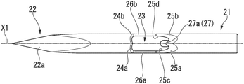
- FIG. 2 is an enlarged cross-sectional view of a distal portion of the tissue collecting instrument.
- FIG. 3 is a view illustrating a first member of the tissue collecting instrument.
- FIG. 4 is a view of the first member viewed from a different direction.
- FIG. 5 is a view of the first member viewed from another different direction.
- FIG. 6 is a view of the first member viewed from yet another different direction.
- FIG. 7 is a view illustrating a second member of the tissue collecting instrument.
- FIG. 8 is a view illustrating a process when the tissue collecting instrument is used.
- FIG. 9 is a view illustrating a process when the tissue collecting instrument is used.
- FIG. 10 is a view illustrating a process when the tissue collecting instrument is used.
- FIG. 11 is a view illustrating a process when the tissue collecting instrument is used.
- FIG. 12 is a view illustrating a process when a modified example of the tissue collecting instrument is used.
- FIG. 13 is an enlarged cross-sectional view schematically illustrating a distal portion of a tissue collecting instrument according to a second embodiment of the present invention.
- FIG. 14 is a view illustrating a process when the tissue collecting instrument is used.
- a tissue collecting instrument 1 includes a long insertion portion 10 , a tissue collecting portion 20 inserted into the insertion portion 10 , and a manipulator 50 provided at a proximal side of the insertion portion 10 and the tissue collecting portion 20 .
- the insertion portion 10 is formed in a tubular shape and has flexibility. As illustrated in FIG. 1 , the insertion portion 10 of the present embodiment is formed of a known coil sheath, but it may be formed of other materials.
- the dimensions of the insertion portion 10 such as a length, an outer diameter, and the like can be appropriately set. For example, they may be set to dimensions such that the insertion portion 10 can be inserted into a treatment instrument channel of an endoscope and be made to protrude from and be retracted into a distal opening of the treatment instrument channel.
- FIG. 2 is an enlarged cross-sectional view illustrating a distal portion of the tissue collecting instrument 1 .
- a first member 21 inserted into the insertion portion 10 and a second member 36 inserted into the first member 21 are provided in the tissue collecting portion 20 .
- the first member 21 is formed of a metal or the like in substantially a tubular shape and has a piercing portion 22 which is sharply formed at the distal end portion.
- the piercing portion 22 has a solid form and a region on the proximal end side from the piercing portion 22 is formed in a tubular shape having an internal space S.
- FIG. 3 is an external view of a distal portion of the first member 21 .
- a part of the outer circumferential surface of the tubular portion near the piercing portion 22 is removed in the first member 21 .
- a side hole 23 communicating with the internal space S is formed at the distal portion of the region formed in a tubular shape in the first member 21 .
- a cutaway surface of the first member 21 is formed on a peripheral edge of the side hole 23 .
- the cutaway surface of the first member 21 has six surfaces in total including a first end surface 24 a and a second end surface 24 b which are formed on the distal side, a first blade surface 25 a and a second blade surface 25 b which are formed on the proximal end side, a first edge surface 26 a positioned between the first end surface 24 a and the first blade surface 25 a , and a second edge surface 26 b positioned between the second end surface 24 b and the second blade surface 25 b .
- the first end surface 24 a , the first edge surface 26 a , and the first blade surface 25 a , and the second end surface 24 b , the second edge surface 26 b , and the second blade surface 25 b , are formed to be symmetrical with respect to the central line of an axis X 1 of the first member 21 .
- All of the aforementioned six surfaces are formed to be flat, but angles formed by the surfaces with respect to the axis X 1 are different.
- the first edge surface 26 a and the second edge surface 26 b are formed parallel to the axis X 1 .
- the first end surface 24 a and the second end surface 24 b as well as the first blade surface 25 a and the second blade surface 25 b are inclined to form angles with respect to the axis X 1 .
- the angle formed by the first blade surface 25 a and the second blade surface 25 b with respect to the axis X 1 is smaller than the angle formed by the first end surface 24 a and the second end surface 24 b with respect to the axis X 1 .
- edge portions near the side hole 23 in the first blade surface 25 a and the second blade surface 25 b are sharp edges 25 c and 25 d (see FIG. 3 ).
- the edges 25 c and 25 d are formed on a curved shape protruding toward the proximal end side of the first member 21 .
- a first protruding portion 27 protruding toward the inside of the side hole 23 is formed at a portion adjacent to the first blade surface 25 a and the second blade surface 25 b . That is, the first blade surface 25 a and the second blade surface 25 b are positioned on both sides of the first protruding portion 27 , and the edges 25 c and 25 d of the first blade surface 25 a and the second blade surface 25 b are continuous to a tip 27 a of the first protruding portion 27 .
- first end surface 24 a As illustrated in FIG. 4 , while the first end surface 24 a , the first edge surface 26 a , and the first blade surface 25 a which are positioned on the same side with respect to the axis X 1 have different angles from each other with respect to the axis X 1 , they have a common parallel axis X 2 extending in a direction perpendicular to the axis X 1 .
- the three flat surfaces of the first end surface 24 a , the first edge surface 26 a , and the first blade surface 25 a can be formed by a single cutting process by moving a laser, a cutter, or the like extending parallel to the parallel axis X 2 without changing the extending direction to cut a part off the outer circumferential surface of the first member 21 .
- the second end surface 24 b , the second edge surface 26 b , and the second blade surface 25 b positioned on the other side with respect to the axis X 1 also have a common parallel axis X 3 extending in a direction perpendicular to the axis X 1 as illustrated in FIG. 5 .
- the side hole 23 having the six surfaces and the first protruding portion 27 in the first member 21 through only two processes by forming the first end surface 24 a , the first edge surface 26 a , and the first blade surface 25 a using a laser, a cutter, or the like extending parallel to the parallel axis X 2 and forming the second end surface 24 b , second edge surface 26 b , and the second blade surface 25 b using a laser, a cutter, or the like extending parallel to the parallel axis X 3 .
- the first member 21 has six surfaces that appear to be a complex shape on the peripheral edge of the side hole 23 , it is actually configured to have extremely excellent processability.
- FIG. 6 is a view of the first member 21 viewed from the side opposite to the opening of the side hole 23 .
- a groove 28 with which the second member 36 is engaged is formed in the region on the proximal end side with respect to the side hole 23 .
- the aforementioned piercing portion 22 has three inclined surfaces 22 a , 22 b , and 22 c which are inclined with respect to the axis X 1 .
- Ridgelines 22 d , 22 e , and 22 f positioned between adjacent inclined surfaces are positioned at different phases from the first protruding portion 27 in a direction around the axis X 1 .
- FIG. 7 is a view illustrating the second member 36 .
- the second member 36 is formed by hollowing out a part of a substantially columnar member, and as illustrated in FIG. 2 , the hollowed-out portion is an accommodating portion 37 for accommodating tissue.
- the second member 36 has a second protruding portion 38 protruding toward the proximal end side with respect to the tip of the accommodating portion 37 .
- the dimension of the region on the distal side with respect to the accommodating portion 37 of substantially a columnar shape in a direction of an axis X 4 is longer than the maximum dimension of the side hole 23 in a direction of the axis X 1 .
- a protrusion 39 is formed on the outer circumferential surface of the second member 36 .
- the second member 36 is inserted into the first member 21 from the distal side so that the protrusion 39 enters the groove 28 . Since the protrusion 39 and the groove 28 are engaged with each other, the second member 36 is disposed to be movable relative to the first member 21 in the direction of the axis X 1 without rotating around the axis X 1 . In a state in which the second member 36 is inserted into the first member 21 , the second protruding portion 38 protrudes in a direction opposite to the first protruding portion 27 .
- the first protruding portion 27 of the first member 21 and the second protruding portion 38 of the second member 36 are positioned at substantially the same phase in a direction around the axis X 1 and face each other.
- the side hole 23 , the internal space S, and the accommodating portion 37 communicate in a state in which the first protruding portion 27 and the second protruding portion 38 are spaced apart and facing each other.
- the side hole 23 is shielded by the outer circumferential surface of the region on the distal side of the second member 36 and the internal space S can be closed.
- the first member 21 and the second member 36 are formed of a material having a rigidity of a predetermined value or higher so as to be suitably operated in the tissue of a subject to be collected.
- a material having a rigidity of a predetermined value or higher so as to be suitably operated in the tissue of a subject to be collected.
- metals and resins are suitable and ultrafine grained stainless steels are particularly suitable.
- a main body 51 to which a proximal end portion of the insertion portion 10 is connected, a first slider 52 connected to the first member 21 , and a second slider 53 connected to the second member 36 are provided in the manipulator 50 .
- the first slider 52 is connected to the first member 21 via a manipulation coil 41 illustrated in FIG. 2 .
- the first slider 52 is disposed to be slidable relative to the main body 51 , and it is possible to make the tissue collecting portion 20 protrude from the insertion portion 10 or accommodate the tissue collecting portion 20 in the insertion portion 10 by sliding the first slider 52 relative to the main body 51 .
- the second slider 53 is connected to the second member 36 via a manipulation wire 42 inserted through the manipulation coil 41 (see FIG. 2 ).
- the second slider 53 is disposed to be slidable relative to the main body 51 and the first slider 52 , and it is possible to move the second member 36 forward and backward relative to the first member 21 by sliding the second slider 53 relative to the first slider 52 .
- tissue collecting instrument 1 of the present embodiment configured as above will be described with reference to a case in which a pancreas is taken as an example of subject tissues to be collected (hereinafter, simply referred to as “subject tissue”).
- an operator introduces an endoscope, which is not illustrated, into a body of a patient and moves the distal end portion of the endoscope close to the pancreas.
- the tissue collecting instrument 1 is inserted into a forceps channel of the endoscope from the distal side thereof in a state in which the tissue collecting portion 20 is accommodated in the insertion portion 10 , and the distal portion of the insertion portion 10 is protruded from a distal opening of the forceps channel.
- the endoscope used may be appropriately selected from a variety of known endoscopes such as optical endoscopes or ultrasonic endoscopes depending on types or positions of subject tissues.
- the operator moves the first slider 52 and the second slider 53 forward relative to the main body 51 so that the tissue collecting portion 20 protrudes from the insertion portion 10 while the pancreas and a site from which a tissue sample is to be collected in the pancreas are observed through endoscope images.
- the second slider 53 is moved back by a predetermined amount relative to the first slider 52 in advance to shield the side hole 23 of the first member 21 .
- the operator pierces the pancreas which is the subject tissue with the piercing portion 22 so that the tissue collecting portion 20 enters the subject tissue St until the side hole 23 enters the subject tissue St while the side hole 23 is maintained in a shielded state, as illustrated in FIG. 8 .
- the operator moves the second slider 53 forward relative to the first slider 52 .
- the second member 36 moves forward relative to the first member 21 , in the first member 21 .
- the side hole 23 is opened and communicates with the accommodating portion 37 of the second member 36 provided in the internal space S.
- the second slider 53 moves to the proximal end side in the first member 21 .
- the second protruding portion 38 stabs tissue St 1 that has entered the accommodating portion 37 as illustrated in FIG. 10 .
- the second member 36 that has been driven into the tissue St 1 pulls the tissue St 1 toward the proximal end side to approach the first protruding portion 27 .
- the tissue St 1 comes into contact with the first protruding portion 27
- the edges 25 c and 25 d continuous with the tip of the first protruding portion 27 are brought into contact with the tissue St 1 , and the tissue St 1 is gradually cut by the first blade surface 25 a and the second blade surface 25 b .
- the tissue St 1 is cut off the subject tissue St and is accommodated in the accommodating portion 37 as illustrated in FIG. 11 .
- the operator moves the tissue collecting portion 20 back and accommodates it in the insertion portion 10 while a state in which the side hole 23 is shielded by the second member 36 is maintained.
- tissue collecting instrument 1 and the endoscope are removed from the body, a sequence of the operation is completed.
- the tissue collecting instrument 1 of the present embodiment in a state in which the side hole 23 of the first member 21 is open to enable some of the subject tissue to enter the internal space S, it is possible for the first protruding portion 27 provided in the first member 21 and the second protruding portion 38 provided in the second member 36 to set in a positional relationship in which the first protruding portion 27 and the second protruding portion 38 face each other in the direction of axis X 1 with the side hole 23 interposed therebetween.
- the tissue St 1 that has entered the internal space S is firmly pierced and hooked by the second protruding portion 38 , and can be reliably moved toward the first protruding portion 27 with which the first blade surface 25 a and the second blade surface 25 b are continuous for cutting the tissue St 1 .
- the tissue St 1 is reliably cut and taken by the first blade surface 25 a and the second blade surface 25 b , and a sufficient volume of tissue sample can be collected without forming negative pressure inside the tissue collecting portion 20 by suction using a syringe or the like.
- the tissue collecting instrument 1 is configured such that the side hole 23 can be shielded by the second member 36 , the side hole 23 is shielded before and after collecting the tissue and it is possible to suitably prevent tissue other than the subject tissue, body fluids, or the like from entering the internal space S.
- tissue other than the subject tissue, body fluids, or the like it is not necessary to use a stylet or the like to prevent foreign substances from being introduced as in conventional biopsy devices, and degradation in flexibility of the tissue collecting portion 20 and the manipulation coil 41 is not caused by insertion of a stylet.
- the piercing portion 22 which pierces the tissue has three inclined surfaces and three ridgelines, and all of the three ridgelines 22 d , 22 e , and 22 f are positioned at different phases from the first protruding portion 27 in the direction around the axis X 1 of the first member 21 .
- the subject tissue St positioned near the side hole 23 is not cut by the ridgelines 22 d , 22 e , and 22 f , and easily enters the internal space S through the side hole 23 .
- the piercing portion is not essential in the tissue collecting instrument of the present invention.
- a tip of a first member 21 A may be formed in a rounded shape such that the tip has a curved surface as in a tissue collecting instrument 1 A of the modified example illustrated in FIG. 12 . Even with such a shape, as illustrated in FIG. 12 , some tissue of a stenosis portion 101 can be reliably collected in a sufficient amount by having a tissue collecting portion 20 A enter the stenosis portion 101 such as a bile duct, a pancreatic duct, or the like.
- a second embodiment of the present invention will be described with reference to FIGS. 13 and 14 .
- a tissue collecting instrument 61 of the present embodiment is different from the tissue collecting instrument 1 of the first embodiment in shapes of the first member and second member.
- components the same as those already described are denoted by the same reference signs and duplicated descriptions thereof will be omitted.
- FIG. 13 is an enlarged cross-sectional view schematically illustrating a distal portion of the tissue collecting instrument 61 .
- a first member 62 is formed in a tubular shape having an opening 63 at its distal end.
- a piercing portion 72 is formed at the distal end portion of a second member 71 .
- the outer circumferential surface of the distal portion of the first member 62 is formed to gradually decrease in outer diameter approaching the opening 63 so that a large step difference with respect to the outer surface of the piercing portion 72 is not formed when the piercing portion 72 protrudes from the opening 63 .
- the second member 71 When subject tissue is pierced by the tissue collecting instrument 61 the second member 71 is moved forward relative to the first member 62 to cause the piercing portion 72 to protrude from the opening 63 and shield a side hole 23 as illustrated in FIG. 13 .
- the side hole 23 is opened to communicate with an internal space S and some of subject tissue St enters the internal space S through the side hole 23 as illustrated in FIG. 14 . Subsequent procedures of collecting tissue is generally the same as the first embodiment.
- tissue collecting instrument 61 of the present embodiment as well, as in the tissue collecting instrument 1 of the first embodiment, a sufficient volume of tissue slice can be reliably collected.
- a known dimple structure may be provided on the surface of the first member or the second member to facilitate visual recognition of the tissue collecting portion with an ultrasonic endoscope.
- first protruding portion and the second protruding portion may be reversed. That is, the first protruding portion may be provided on the distal side of the tissue collecting instrument, and the second protruding portion may be provided on the proximal side of the tissue collecting instrument. In this case, the tissue is collected by moving the second member forward relative to the first member.
- tissue collecting portion may be configured such that the tissue is directly accommodated in the internal space of the first member without an accommodating portion provided in the second member.
- the cutaway shape of the first member formed on the peripheral edge of the side hole is not limited to that having the above-described six surfaces, and may be appropriately modified.
- it may be configured to have four surfaces by making the first edge surface and the first end surface into one continuous surface.
- the second end surface, the second edge surface, and the second blade surface may be formed not to have a common parallel axis while the first end surface, the first edge surface, and the first blade surface may be formed to have a common parallel axis.
- the same effect of tissue collecting performance as that of the above-described embodiments is achieved.
- Subject tissues of the tissue collecting instrument of the present invention are not limited to the above-described pancreas or bile duct. Therefore, any tissue that can be approached by various known endoscopes can be a subject.
Landscapes
- Health & Medical Sciences (AREA)
- Life Sciences & Earth Sciences (AREA)
- Surgery (AREA)
- Biomedical Technology (AREA)
- Engineering & Computer Science (AREA)
- Pathology (AREA)
- Heart & Thoracic Surgery (AREA)
- Medical Informatics (AREA)
- Molecular Biology (AREA)
- Animal Behavior & Ethology (AREA)
- General Health & Medical Sciences (AREA)
- Public Health (AREA)
- Veterinary Medicine (AREA)
- Nuclear Medicine, Radiotherapy & Molecular Imaging (AREA)
- Surgical Instruments (AREA)
Abstract
Description
Claims (2)
Priority Applications (1)
| Application Number | Priority Date | Filing Date | Title |
|---|---|---|---|
| US15/496,373 US11229423B2 (en) | 2016-04-27 | 2017-04-25 | Tissue collecting instrument |
Applications Claiming Priority (3)
| Application Number | Priority Date | Filing Date | Title |
|---|---|---|---|
| JP2016-089749 | 2016-04-27 | ||
| JP2016089749A JP6811441B2 (en) | 2016-04-27 | 2016-04-27 | Tissue collection tool |
| US15/496,373 US11229423B2 (en) | 2016-04-27 | 2017-04-25 | Tissue collecting instrument |
Publications (2)
| Publication Number | Publication Date |
|---|---|
| US20170311936A1 US20170311936A1 (en) | 2017-11-02 |
| US11229423B2 true US11229423B2 (en) | 2022-01-25 |
Family
ID=60157089
Family Applications (1)
| Application Number | Title | Priority Date | Filing Date |
|---|---|---|---|
| US15/496,373 Active 2039-04-03 US11229423B2 (en) | 2016-04-27 | 2017-04-25 | Tissue collecting instrument |
Country Status (2)
| Country | Link |
|---|---|
| US (1) | US11229423B2 (en) |
| JP (1) | JP6811441B2 (en) |
Families Citing this family (2)
| Publication number | Priority date | Publication date | Assignee | Title |
|---|---|---|---|---|
| KR102026938B1 (en) * | 2017-06-13 | 2019-09-30 | 주식회사 파인메딕스 | Hybrid knife for endoscope |
| CA3074285A1 (en) * | 2019-09-10 | 2021-03-09 | Lenkbar, Llc | Cutting head for tissue collection device |
Citations (21)
| Publication number | Priority date | Publication date | Assignee | Title |
|---|---|---|---|---|
| JPS5450359A (en) | 1977-09-29 | 1979-04-20 | Toshiba Corp | Radiation thickness gauge |
| EP0019104A2 (en) * | 1979-05-19 | 1980-11-26 | Intermedicat GmbH | Biopsy needle for sampling histological specimens |
| US5320110A (en) | 1991-10-29 | 1994-06-14 | Wang Ko P | Pleural biopsy syringe-needles |
| US5458112A (en) | 1994-08-15 | 1995-10-17 | Arrow Precision Products, Inc. | Biliary biopsy device |
| US5507742A (en) * | 1993-12-02 | 1996-04-16 | Laser Centers Of America | Multifunction laser-powered surgical tool with optical electrocautery capability |
| JPH10137248A (en) | 1996-11-13 | 1998-05-26 | Olympus Optical Co Ltd | Suction biopsy tool |
| US20020022788A1 (en) | 1999-08-19 | 2002-02-21 | Tim Corvi | Apparatus and methods for material capture and removal |
| US20050070818A1 (en) | 2003-09-30 | 2005-03-31 | Mueller Richard L. | Biopsy device with viewing assembly |
| JP2006095312A (en) | 2004-09-29 | 2006-04-13 | Ethicon Endo Surgery Inc | Biopsy device and method |
| US20070106176A1 (en) * | 2003-10-14 | 2007-05-10 | Mark Joseph L | Vacuum assisted biopsy needle set |
| US20100145225A1 (en) * | 2008-12-09 | 2010-06-10 | Wilson-Cook Medical Inc. | Cytology Device |
| USD657461S1 (en) * | 2011-04-04 | 2012-04-10 | Cook Medical Technologies Llc | Biopsy needle tip |
| JP2012509096A (en) | 2008-11-18 | 2012-04-19 | ヒボン パク | Biopsy device |
| US20130046316A1 (en) | 2011-08-18 | 2013-02-21 | Hologic, Inc. | Tissue removal system |
| JP2013523333A (en) | 2010-04-06 | 2013-06-17 | クック メディカル テクノロジーズ エルエルシー | Endoscopic ultrasound guided biopsy needle |
| JP2013538615A (en) | 2010-09-03 | 2013-10-17 | デビコー・メディカル・プロダクツ・インコーポレイテッド | Echogenic needle for a biopsy device |
| US20140100448A1 (en) | 2012-10-10 | 2014-04-10 | Cook Medical Technologies Llc | Rotary sample-collection needle |
| US9844362B2 (en) * | 2015-01-13 | 2017-12-19 | Covidien Lp | Exchangeable core biopsy needle |
| US10034684B2 (en) * | 2015-06-15 | 2018-07-31 | Ethicon Llc | Apparatus and method for dissecting and coagulating tissue |
| US20180228476A1 (en) * | 2017-02-15 | 2018-08-16 | Cook Medical Technologies Llc | Endoscopic tri-point biopsy needle |
| US20200205794A1 (en) * | 2017-05-11 | 2020-07-02 | Snpshot Trustee Limited | A tissue sample punch |
-
2016
- 2016-04-27 JP JP2016089749A patent/JP6811441B2/en active Active
-
2017
- 2017-04-25 US US15/496,373 patent/US11229423B2/en active Active
Patent Citations (21)
| Publication number | Priority date | Publication date | Assignee | Title |
|---|---|---|---|---|
| JPS5450359A (en) | 1977-09-29 | 1979-04-20 | Toshiba Corp | Radiation thickness gauge |
| EP0019104A2 (en) * | 1979-05-19 | 1980-11-26 | Intermedicat GmbH | Biopsy needle for sampling histological specimens |
| US5320110A (en) | 1991-10-29 | 1994-06-14 | Wang Ko P | Pleural biopsy syringe-needles |
| US5507742A (en) * | 1993-12-02 | 1996-04-16 | Laser Centers Of America | Multifunction laser-powered surgical tool with optical electrocautery capability |
| US5458112A (en) | 1994-08-15 | 1995-10-17 | Arrow Precision Products, Inc. | Biliary biopsy device |
| JPH10137248A (en) | 1996-11-13 | 1998-05-26 | Olympus Optical Co Ltd | Suction biopsy tool |
| US20020022788A1 (en) | 1999-08-19 | 2002-02-21 | Tim Corvi | Apparatus and methods for material capture and removal |
| US20050070818A1 (en) | 2003-09-30 | 2005-03-31 | Mueller Richard L. | Biopsy device with viewing assembly |
| US20070106176A1 (en) * | 2003-10-14 | 2007-05-10 | Mark Joseph L | Vacuum assisted biopsy needle set |
| JP2006095312A (en) | 2004-09-29 | 2006-04-13 | Ethicon Endo Surgery Inc | Biopsy device and method |
| JP2012509096A (en) | 2008-11-18 | 2012-04-19 | ヒボン パク | Biopsy device |
| US20100145225A1 (en) * | 2008-12-09 | 2010-06-10 | Wilson-Cook Medical Inc. | Cytology Device |
| JP2013523333A (en) | 2010-04-06 | 2013-06-17 | クック メディカル テクノロジーズ エルエルシー | Endoscopic ultrasound guided biopsy needle |
| JP2013538615A (en) | 2010-09-03 | 2013-10-17 | デビコー・メディカル・プロダクツ・インコーポレイテッド | Echogenic needle for a biopsy device |
| USD657461S1 (en) * | 2011-04-04 | 2012-04-10 | Cook Medical Technologies Llc | Biopsy needle tip |
| US20130046316A1 (en) | 2011-08-18 | 2013-02-21 | Hologic, Inc. | Tissue removal system |
| US20140100448A1 (en) | 2012-10-10 | 2014-04-10 | Cook Medical Technologies Llc | Rotary sample-collection needle |
| US9844362B2 (en) * | 2015-01-13 | 2017-12-19 | Covidien Lp | Exchangeable core biopsy needle |
| US10034684B2 (en) * | 2015-06-15 | 2018-07-31 | Ethicon Llc | Apparatus and method for dissecting and coagulating tissue |
| US20180228476A1 (en) * | 2017-02-15 | 2018-08-16 | Cook Medical Technologies Llc | Endoscopic tri-point biopsy needle |
| US20200205794A1 (en) * | 2017-05-11 | 2020-07-02 | Snpshot Trustee Limited | A tissue sample punch |
Non-Patent Citations (2)
| Title |
|---|
| Japanese Office Action for JP Application No. 2016-089749 dated Feb. 6, 2020. |
| Japanese Office Action issued for JP 2016-089749 dated Jul. 13, 2020. |
Also Published As
| Publication number | Publication date |
|---|---|
| JP6811441B2 (en) | 2021-01-13 |
| JP2017196188A (en) | 2017-11-02 |
| US20170311936A1 (en) | 2017-11-02 |
Similar Documents
| Publication | Publication Date | Title |
|---|---|---|
| EP2982309B1 (en) | Exchangeable core biopsy needle | |
| US9237884B2 (en) | Treatment device for endoscope | |
| EP3260050B1 (en) | Biopsy needle | |
| EP3045118B1 (en) | Exchangable core biopsy needle | |
| JP5908198B1 (en) | Needle tube | |
| JP2020518369A (en) | Endoscopic biopsy needle tip and method of use | |
| US20220273274A1 (en) | Biopsy needle and tissue collecting device | |
| JP7442003B2 (en) | Puncture needle for endoscope | |
| US11229423B2 (en) | Tissue collecting instrument | |
| KR102065068B1 (en) | Needle structure of core biopsy device | |
| JP5945651B1 (en) | Biopsy needle | |
| EP2904976B1 (en) | Biopsy instrument | |
| CN222323584U (en) | Needle tube and biopsy device | |
| JP7263055B2 (en) | biopsy needle | |
| US20220104796A1 (en) | Biopsy needle assembly and method |
Legal Events
| Date | Code | Title | Description |
|---|---|---|---|
| AS | Assignment |
Owner name: NANO GRAINS CO., LTD., JAPAN Free format text: ASSIGNMENT OF ASSIGNORS INTEREST;ASSIGNOR:SUZUKI, KEITA;REEL/FRAME:042136/0615 Effective date: 20170420 |
|
| STPP | Information on status: patent application and granting procedure in general |
Free format text: DOCKETED NEW CASE - READY FOR EXAMINATION |
|
| STPP | Information on status: patent application and granting procedure in general |
Free format text: NON FINAL ACTION MAILED |
|
| STPP | Information on status: patent application and granting procedure in general |
Free format text: RESPONSE TO NON-FINAL OFFICE ACTION ENTERED AND FORWARDED TO EXAMINER |
|
| STPP | Information on status: patent application and granting procedure in general |
Free format text: FINAL REJECTION MAILED |
|
| STPP | Information on status: patent application and granting procedure in general |
Free format text: RESPONSE AFTER FINAL ACTION FORWARDED TO EXAMINER |
|
| STPP | Information on status: patent application and granting procedure in general |
Free format text: NOTICE OF ALLOWANCE MAILED -- APPLICATION RECEIVED IN OFFICE OF PUBLICATIONS |
|
| STPP | Information on status: patent application and granting procedure in general |
Free format text: PUBLICATIONS -- ISSUE FEE PAYMENT VERIFIED |
|
| STCF | Information on status: patent grant |
Free format text: PATENTED CASE |
|
| MAFP | Maintenance fee payment |
Free format text: PAYMENT OF MAINTENANCE FEE, 4TH YR, SMALL ENTITY (ORIGINAL EVENT CODE: M2551); ENTITY STATUS OF PATENT OWNER: SMALL ENTITY Year of fee payment: 4 |