US11228465B1 - Rapid training method for high-speed ethernet - Google Patents
Rapid training method for high-speed ethernet Download PDFInfo
- Publication number
- US11228465B1 US11228465B1 US16/362,479 US201916362479A US11228465B1 US 11228465 B1 US11228465 B1 US 11228465B1 US 201916362479 A US201916362479 A US 201916362479A US 11228465 B1 US11228465 B1 US 11228465B1
- Authority
- US
- United States
- Prior art keywords
- level symbols
- symbols
- level
- training
- precoder
- Prior art date
- Legal status (The legal status is an assumption and is not a legal conclusion. Google has not performed a legal analysis and makes no representation as to the accuracy of the status listed.)
- Active, expires
Links
Images


Classifications
-
- H—ELECTRICITY
- H04—ELECTRIC COMMUNICATION TECHNIQUE
- H04L—TRANSMISSION OF DIGITAL INFORMATION, e.g. TELEGRAPHIC COMMUNICATION
- H04L25/00—Baseband systems
- H04L25/02—Details ; arrangements for supplying electrical power along data transmission lines
- H04L25/0202—Channel estimation
- H04L25/0224—Channel estimation using sounding signals
- H04L25/0228—Channel estimation using sounding signals with direct estimation from sounding signals
- H04L25/023—Channel estimation using sounding signals with direct estimation from sounding signals with extension to other symbols
-
- H—ELECTRICITY
- H04—ELECTRIC COMMUNICATION TECHNIQUE
- H04L—TRANSMISSION OF DIGITAL INFORMATION, e.g. TELEGRAPHIC COMMUNICATION
- H04L25/00—Baseband systems
- H04L25/38—Synchronous or start-stop systems, e.g. for Baudot code
- H04L25/40—Transmitting circuits; Receiving circuits
- H04L25/49—Transmitting circuits; Receiving circuits using code conversion at the transmitter; using predistortion; using insertion of idle bits for obtaining a desired frequency spectrum; using three or more amplitude levels ; Baseband coding techniques specific to data transmission systems
- H04L25/497—Transmitting circuits; Receiving circuits using code conversion at the transmitter; using predistortion; using insertion of idle bits for obtaining a desired frequency spectrum; using three or more amplitude levels ; Baseband coding techniques specific to data transmission systems by correlative coding, e.g. partial response coding or echo modulation coding transmitters and receivers for partial response systems
- H04L25/4975—Correlative coding using Tomlinson precoding, Harashima precoding, Trellis precoding or GPRS
-
- H—ELECTRICITY
- H04—ELECTRIC COMMUNICATION TECHNIQUE
- H04L—TRANSMISSION OF DIGITAL INFORMATION, e.g. TELEGRAPHIC COMMUNICATION
- H04L1/00—Arrangements for detecting or preventing errors in the information received
- H04L1/0001—Systems modifying transmission characteristics according to link quality, e.g. power backoff
- H04L1/0002—Systems modifying transmission characteristics according to link quality, e.g. power backoff by adapting the transmission rate
- H04L1/0003—Systems modifying transmission characteristics according to link quality, e.g. power backoff by adapting the transmission rate by switching between different modulation schemes
-
- H—ELECTRICITY
- H04—ELECTRIC COMMUNICATION TECHNIQUE
- H04L—TRANSMISSION OF DIGITAL INFORMATION, e.g. TELEGRAPHIC COMMUNICATION
- H04L1/00—Arrangements for detecting or preventing errors in the information received
- H04L1/004—Arrangements for detecting or preventing errors in the information received by using forward error control
- H04L1/0041—Arrangements at the transmitter end
-
- H—ELECTRICITY
- H04—ELECTRIC COMMUNICATION TECHNIQUE
- H04L—TRANSMISSION OF DIGITAL INFORMATION, e.g. TELEGRAPHIC COMMUNICATION
- H04L1/00—Arrangements for detecting or preventing errors in the information received
- H04L1/004—Arrangements for detecting or preventing errors in the information received by using forward error control
- H04L1/0045—Arrangements at the receiver end
- H04L1/0046—Code rate detection or code type detection
-
- H—ELECTRICITY
- H04—ELECTRIC COMMUNICATION TECHNIQUE
- H04L—TRANSMISSION OF DIGITAL INFORMATION, e.g. TELEGRAPHIC COMMUNICATION
- H04L1/00—Arrangements for detecting or preventing errors in the information received
- H04L1/004—Arrangements for detecting or preventing errors in the information received by using forward error control
- H04L1/0056—Systems characterized by the type of code used
- H04L1/0057—Block codes
-
- H—ELECTRICITY
- H04—ELECTRIC COMMUNICATION TECHNIQUE
- H04L—TRANSMISSION OF DIGITAL INFORMATION, e.g. TELEGRAPHIC COMMUNICATION
- H04L25/00—Baseband systems
- H04L25/02—Details ; arrangements for supplying electrical power along data transmission lines
- H04L25/0202—Channel estimation
- H04L25/0224—Channel estimation using sounding signals
- H04L25/0226—Channel estimation using sounding signals sounding signals per se
-
- H—ELECTRICITY
- H04—ELECTRIC COMMUNICATION TECHNIQUE
- H04L—TRANSMISSION OF DIGITAL INFORMATION, e.g. TELEGRAPHIC COMMUNICATION
- H04L25/00—Baseband systems
- H04L25/02—Details ; arrangements for supplying electrical power along data transmission lines
- H04L25/03—Shaping networks in transmitter or receiver, e.g. adaptive shaping networks
- H04L25/03006—Arrangements for removing intersymbol interference
- H04L25/03343—Arrangements at the transmitter end
Definitions
- the disclosure herein relates to communications systems, and more specifically to high-speed Ethernet systems and methods.
- Modern high-speed Ethernet protocols such as 10GBASE-T and NBASE-T, rely on adaptive filters and digital signal processing circuitry to address noise that may affect the Ethernet link.
- the link Prior to operation of the link in an “online” mode, the link undergoes autonegotiation and a full training sequence to place the link in an initial state that's capable of overcoming the noise.
- the link While operating in the “online” mode, the link may briefly go “offline” due to extraneous alien crosstalk or other noise.
- Fast retrain sequences may bring the link back online in a very short period of time without the need to carry out a full training sequence.
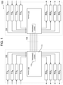
- FIG. 1 illustrates a high-level transmitter/receiver (transceiver) channel architecture for an NBASE-T Ethernet transceiver.
- FIG. 2 illustrates a flowchart of steps for one embodiment of a method for performing a full training sequence for initializing a link.
- FIG. 3 illustrates a flowchart of steps for one embodiment of a method for performing a fast retrain sequence for a link.
- FIG. 1 is a block diagram illustrating one embodiment of a communication system 100 .
- the system includes a first transceiver integrated circuit (IC) or chip 102 and a second transceiver chip 104 that can communicate with each other.
- the first transceiver 102 includes “transceiver components” including one or more transmitters TX A -TX D and one or more receivers RX A -RX D .
- the second transceiver 104 includes various transceiver components including one or more transmitters TX E -TX H and one or more receivers RX E -RX H .
- receivers RX A -RX H can be considered individual “receivers,” as typically referenced herein, or can alternately be considered individual receiver channels which a receiver block within the transceiver can independently receive signals on.
- the transmitters and receivers are connected to one or more components (not shown) of a computer system, device, processor, or other “controller” associated with each respective transceiver which wants to communicate data over the communication network.
- the transmitters receive data and control signals from the controller connected to the first transceiver 102 in order to send the data over the network to other transceivers and controllers, while the receivers receive data from other transceivers and controllers via the network in order to provide the data to the controller connected to the first transceiver 102 .
- the first transceiver chip 102 can communicate with the second transceiver chip 104 over one or more communication channels of a communication link 106 .
- a communication link 106 In one embodiment, such as one similar to the 10GBASE-T Ethernet standard, four communication channels are provided on the communication link 106 , each channel including a twisted pair cable.
- there are four transmitters TX and four corresponding receivers RX provided in each of the transceivers 102 and 104 each transmitter associated with one of the local near-end receivers in the same transceiver, and each such transmitter/receiver pair dedicated to one channel used for duplex communication.
- a transmitter/receiver pair in the first transceiver 102 communicates across a channel of the link 106 to a far-end transmitter/receiver pair in the second transceiver 104 .
- a transmitter TX and a receiver RX that are connected to the same channel/link, or two transceivers connected by the communication link 106 are considered “link partners.”
- the transmitters cooperate with precoders (not shown), and more specifically Tomlinson-Harashima precoders (THP) that apply THP coefficients to transmit signals to pre-compensate for channel imperfections and expected noise/distortion.
- THP Tomlinson-Harashima precoders
- An interface 108 can be provided in the first transceiver chip 102 and an interface 110 can be provided in the second transceiver chip 104 to allow data transmissions between the transceivers to be routed to the appropriate transceiver blocks.
- the interfaces 108 and 110 can include transformers, and circuitry used for directing signals or data (alternatively, some or all circuitry can be included in other components, such as transmitters TX and receivers RX).
- the interface 108 for each chip includes training logic 112 that manages and controls full training sequences and rapid retrain operations, as more fully explained below.
- the training logic associated with the interface 108 may be shared amongst the channels, or provided as separate resources for each of the transceiver channels.
- FIG. 2 illustrates steps employed for one embodiment of a full training sequence, generally designated 200 , used to train the parameters of each link partner transceiver to achieve fully-functional nominal operation.
- Nominal operation is a predefined level of operation at which parameters are at a particular target level (such as bit error rate being under a particular target rate), and for which the transceiver can transmit and receive data over the link.
- the full training sequence is a predefined sequence of stages or steps known by each of the link partners, although the boundaries of each step in the sequence may be overlapped or blurred in some embodiments.
- the sequence typically occurs at a predefined point of operation, such as at startup when a transceiver is powered on or is first connected to a communication link.
- the transceiver During nominal operation, after the full training sequence, the transceiver continues to adapt parameters to changing characteristics of the link based on received data. However, some characteristics change so quickly that the receiver cannot adapt quickly enough, due to noise, interference, or other disturbances, which sometimes cause the loss of the link.
- the full training sequence is used to re-train transceiver parameters when a transceiver loses a communication link in a manner such that a fast retrain sequence cannot bring up the link.
- the full training sequence example of FIG. 2 is an example pertinent to the 10GBASE-T and NBASE-T communication standards, but other full training sequences may be used in other embodiments.
- the full training sequence 200 may optionally first include a calibration process, at 202 .
- the calibration process is typically not part of a communication standard, but is often employed to allow the transceiver components to operate near optimal condition.
- the calibration process may include calibration of analog front end (AFE) components of the transceiver such as a digital-to-analog converter (DAC), line driver, low pass filter, gain stage, and analog-to-digital converter (ADC).
- AFE analog front end
- the calibration does not occur only in step 202 , but may continue to occur during parts or all of the training or retraining sequence.
- the calibration cooperates with a determination step, described below, for confirming whether a sequence of precoded training signals may be omitted in an effort to significantly reduce training time.
- the full training sequence 200 includes an autonegotiation step, at 204 .
- the autonegotiation step involves having the link partners communicate across the communication link to establish the common conditions under which normal data communication will operate.
- the autonegotiation step can include determining which communication standard to use (10GBASE-T, NBASE-T, etc.), and determining which link partner will be the Master and which one will be the Slave (the Slave recovers timing information from the Master needed for communication). Additional information such as support for fast retrains may also be advertised between the link partners.
- a pulse-amplitude modulation-2 (PAM-2) training signal transmission occurs next, at 206 .
- a PAM-2 signal has only 2 signal levels to transmit (e.g., bits are translated to either of two signal levels, e.g., +1V and ⁇ 1V), and since the levels are further apart than in a modulation scheme having a greater number of levels, PAM-2 signals are easier to decode and detect in a higher-noise environment. As a result, the signals are more suitable for transmission during training, when the communication may be more prone to noise and error.
- DSQ128 signals are typically used during normal transmission for the 10GBASE-T format, which, similar to PAM-16, allows 16 levels of signal after the receiver parameters have been trained. This allows many more signal levels to be used for a symbol, which may thus represent multiple bits.
- the PAM-2 signals can be used to determine a transmitter gain and a setting for a power backoff adjustment, described below, among other functions such as adapting filters and equalizers and clock-timing recovery. Furthermore, during the PAM-2 sequence, the receiver gain may be determined so that the receiver gain may be updated and adapted.
- the training next involves a power backoff step, at 208 .
- the power level used for transmission may be reduced down to a minimum level needed for communication, thus saving power during operation while reducing noise such as crosstalk to and from adjacent communication ports of the transceiver.
- Examples of signal quality parameters or indicators may involve signal-to-noise ratio (SNR) or received signals, or some form of linearity evaluation of signals propagating along the link. If the signals fail to meet a threshold signal quality level, which will often be in rare circumstances, then the standardized sequence of steps continues below consistent with a “legacy” full training mode. Should the PAM-2 training signals meet the signal quality threshold, then a reduced-step full training mode may be entered, described more fully below, to significantly reduce the time to train the link.
- SNR signal-to-noise ratio
- a further PAM-2 training sequence may be carried out, at 212 , which also includes a determination of precoder coefficients for the link partner transmitters.
- the precoder coefficients correspond to Tomlinson-Harashima Precoding (THP) coefficients.
- THP Tomlinson-Harashima Precoding
- the determined coefficients for each transmitter may be exchanged between the link partners so that each transceiver has the appropriate precoder coefficients as determined by its link partner, and the receiver is synchronized with the transmitter that is now using the precoding.
- the PAM-2 training signal is transmitted with the precoding, at 214 , using the appropriate coefficients and other parameters determined above.
- the precoding applied to the PAM-2 signal allows the far-end receiver to retune its filters for the potential difference between optimal operating points with and without the precoding, so that the same adaptation can be used during normal transmission (since THP is sent by the transmitter, it is not adapted to during normal data reception by the receiver).
- a transition period occurs, at 216 , to allow the link to transition from transmitting the precoded PAM-2 signals, to transmitting a multi-PAM type of signal having characteristics more closely resembling those actually used during nominal operation, such as a PAM-16 signal.
- actual PAM-16 training signals encoded with the THP coefficients, and modulated via a DSQ128 type of modulation may be transmitted, at 218 .
- the training sequence ends and normal operation begins, in which actual data is transmitted and received over the link as PAM-16 signals.
- the time expended to carry out the PAM-2THP steps 214 and 216 may take up to 650 milliseconds or more.
- ADCs and DAC architectures With ever-improving signaling media, ADCs and DAC architectures, the signal quality of the initial PAM-2 signals transmitted during the training sequence is often very good. Consequently, incremental training steps such as encoding the PAM-2 signals with the THP coefficients are often “overkill”, yet take relatively long times to carry out.
- one embodiment provides for a reduced-processing training mode, beginning at 220 , that omits the legacy PAM-2THP steps, resulting in a reduction in training time by approximately 32%.
- a separate “legacy” mode of full training may not be provided as a separate mode from the reduced-processing training mode, especially in circumstances where a certain minimal level of signal quality is expected from the link.
- a communication between link partners in the reduced-processing training mode is carried out, at 220 . This is carried out so that the partners know that the reduced-processing mode steps will be followed, instead of the legacy mode steps.
- This communication may be made by, for example, an InfoField protocol that includes one or more bits flagging use of the reduced-processing full training mode.
- the THP coefficients may be determined, and exchanged, at 222 , in a manner similar to the legacy training mode. Following the coefficient exchange, however, instead of carrying out a PAM-2THP training sequence with the associated transition time, the reduced-processing full training mode goes directly to a PAM-16THP step, at 224 , to run a training sequence of PAM-16 signals encoded by the THP coefficients determined earlier.
- a full training sequence may be reduced by approximately 650 milliseconds, which is almost a third of the typical two seconds often allocated to a full training sequence.
- a fast retrain method provides multiple fast retrain modes of operation in an Ethernet transceiver that can enable a fast link recovery for a link affected by a change in noise or some other undesirable distortion characteristic.
- a fast retrain sequence may be initiated, at 302 .
- a fast retrain is a brief link training sequence that resets a minimal number of link parameters to allow for changes in link parameters without necessarily requiring the link to go offline for a full auto-negotiation and training cycle, which may take a few seconds.
- the fast retrain sequence first provides a PAM-2 transmission sequence, at 304 .
- the PAM-2 training sequence allows updating of transceiver parameters.
- THP precoding coefficients as well as receiver equalizers and other filters can also be re-optimized due to the new noisy environment.
- one embodiment provides a legacy fast retraining mode that follows standardized fast retraining sequences where the detected signal quality is under a certain threshold, determined at 306 .
- a second fast retrain mode involves reducing steps even further, where the signal quality of the link remains above a certain threshold.
- the newly updated THP coefficients are exchanged between link partners and the receiver synchronized with precoded transmission data from the far-end link partner transmitter, at 308 .
- other signal types, modulations, or formats can be used for training signals as appropriate.
- the PAM-2 training signal is transmitted with the precoding, at 310 , using the appropriate coefficients and other parameters determined above.
- the precoding applied to the PAM-2 signal allows the far-end receiver to retune its filters for the potential difference between optimal operating points with and without the precoding, so that the same adaptation can be used during normal transmission.
- a transition period occurs, at 312 , to allow the link to transition from transmitting the precoded PAM-2 signals, to transmitting a multi-PAM type of signal having characteristics more closely resembling those actually used during nominal operation, such as a PAM-16 signal.
- actual PAM-16 training signals encoded with the THP coefficients, and modulated via a DSQ128 type of modulation may be transmitted, at 314 .
- the training sequence ends and normal operation begins, in which actual data is transmitted and received over the link as PAM-16 signals.
- the time expended to carry out the PAM-2THP steps 310 and 312 may take up to 10 milliseconds or more. This is approximately one-third of the timing budget allotted to each fast retrain sequence.
- one embodiment provides for a reduced-processing fast retrain mode, beginning at 316 , that omits the legacy PAM-2THP steps. This results in a training time reduction by approximately one-third. Note that in some embodiments, a separate “legacy” mode of fast retraining may not be provided as a separate mode from the reduced-processing training mode.
- a communication between link partners in the reduced-processing training mode is carried out, at 316 .
- This is carried out similar to the full training sequence, so that the partners know that the reduced-processing fast retrain mode will be followed, instead of the legacy mode.
- This communication may be made by, for example, an InfoField protocol that includes one or more bits flagging use of the reduced-processing training mode.
- the THP coefficients may be determined, and exchanged, at 318 , in a manner similar to the legacy training mode.
- the reduced-processing mode goes straight to a PAM-16THP step, at 320 , to run a training sequence of PAM-16 signals encoded by the THP coefficients determined earlier.
- a full training sequence may be shortened by approximately 10 milliseconds, which is almost a third of the typical 30 milliseconds often allocated to a legacy fast retrain sequence. Since fast retrains may occur often during normal operation of the link, repetitive fast retrain sequences of shorter duration saves significant time.
- Such data and/or instruction-based expressions of the above described circuits may be processed by a processing entity (e.g., one or more processors) within the computer system in conjunction with execution of one or more other computer programs including, without limitation, net-list generation programs, place and route programs and the like, to generate a representation or image of a physical manifestation of such circuits.
- a processing entity e.g., one or more processors
- Such representation or image may thereafter be used in device fabrication, for example, by enabling generation of one or more masks that are used to form various components of the circuits in a device fabrication process.
- signals described or depicted as having active-high or active-low logic levels may have opposite logic levels in alternative embodiments.
- Component circuitry within integrated circuit devices may be implemented using metal oxide semiconductor (MOS) technology, bipolar technology or any other technology in which logical and analog circuits may be implemented.
- MOS metal oxide semiconductor
- a signal is said to be “asserted” when the signal is driven to a low or high logic state (or charged to a high logic state or discharged to a low logic state) to indicate a particular condition.
- a signal is said to be “deasserted” to indicate that the signal is driven (or charged or discharged) to a state other than the asserted state (including a high or low logic state, or the floating state that may occur when the signal driving circuit is transitioned to a high impedance condition, such as an open drain or open collector condition).
- a signal driving circuit is said to “output” a signal to a signal receiving circuit when the signal driving circuit asserts (or deasserts, if explicitly stated or indicated by context) the signal on a signal line coupled between the signal driving and signal receiving circuits.
- a signal line is said to be “activated” when a signal is asserted on the signal line, and “deactivated” when the signal is deasserted.
- the prefix symbol “I” attached to signal names indicates that the signal is an active low signal (i.e., the asserted state is a logic low state).
- a line over a signal name e.g., ‘ ⁇ signal name> ’ is also used to indicate an active low signal.
- the term “coupled” is used herein to express a direct connection as well as a connection through one or more intervening circuits or structures.
- Integrated circuit device “programming” may include, for example and without limitation, loading a control value into a register or other storage circuit within the device in response to a host instruction and thus controlling an operational aspect of the device, establishing a device configuration or controlling an operational aspect of the device through a one-time programming operation (e.g., blowing fuses within a configuration circuit during device production), and/or connecting one or more selected pins or other contact structures of the device to reference voltage lines (also referred to as strapping) to establish a particular device configuration or operation aspect of the device.
- a one-time programming operation e.g., blowing fuses within a configuration circuit during device production
- reference voltage lines also referred to as strapping
Abstract
A method of operation for an Ethernet transceiver is disclosed. The method includes entering a training sequence. The training sequence includes transferring uncoded two-level symbols to a link partner; exchanging updated precoder coefficients with the link partner; and directly following exchanging updated precoder coefficients, transferring multi-level symbols to the link partner. The multi-level symbols being encoded consistent with the exchanged updated precoder coefficients and having greater than two symbol levels.
Description
The disclosure herein relates to communications systems, and more specifically to high-speed Ethernet systems and methods.
Modern high-speed Ethernet protocols, such as 10GBASE-T and NBASE-T, rely on adaptive filters and digital signal processing circuitry to address noise that may affect the Ethernet link. Prior to operation of the link in an “online” mode, the link undergoes autonegotiation and a full training sequence to place the link in an initial state that's capable of overcoming the noise. While operating in the “online” mode, the link may briefly go “offline” due to extraneous alien crosstalk or other noise. Fast retrain sequences may bring the link back online in a very short period of time without the need to carry out a full training sequence.
Conventional training sequences for high-speed Ethernet links generally take approximately two seconds for full training, and approximately 30 milliseconds for a fast retraining. For many applications, such time durations for training functions may be undesirable.
Embodiments of the disclosure are illustrated by way of example, and not by way of limitation, in the figures of the accompanying drawings and in which like reference numerals refer to similar elements and in which:
The first transceiver chip 102 can communicate with the second transceiver chip 104 over one or more communication channels of a communication link 106. In one embodiment, such as one similar to the 10GBASE-T Ethernet standard, four communication channels are provided on the communication link 106, each channel including a twisted pair cable. Thus, in that standard, there are four transmitters TX and four corresponding receivers RX provided in each of the transceivers 102 and 104, each transmitter associated with one of the local near-end receivers in the same transceiver, and each such transmitter/receiver pair dedicated to one channel used for duplex communication. A transmitter/receiver pair in the first transceiver 102 communicates across a channel of the link 106 to a far-end transmitter/receiver pair in the second transceiver 104. A transmitter TX and a receiver RX that are connected to the same channel/link, or two transceivers connected by the communication link 106, are considered “link partners.” In accordance with the 10GBASE-T standard, the transmitters cooperate with precoders (not shown), and more specifically Tomlinson-Harashima precoders (THP) that apply THP coefficients to transmit signals to pre-compensate for channel imperfections and expected noise/distortion.
An interface 108 can be provided in the first transceiver chip 102 and an interface 110 can be provided in the second transceiver chip 104 to allow data transmissions between the transceivers to be routed to the appropriate transceiver blocks. For example, the interfaces 108 and 110 can include transformers, and circuitry used for directing signals or data (alternatively, some or all circuitry can be included in other components, such as transmitters TX and receivers RX).
For one embodiment, the interface 108 for each chip includes training logic 112 that manages and controls full training sequences and rapid retrain operations, as more fully explained below. The training logic associated with the interface 108 may be shared amongst the channels, or provided as separate resources for each of the transceiver channels.
Further referring to FIG. 2 , the full training sequence 200 may optionally first include a calibration process, at 202. The calibration process is typically not part of a communication standard, but is often employed to allow the transceiver components to operate near optimal condition. For example, the calibration process may include calibration of analog front end (AFE) components of the transceiver such as a digital-to-analog converter (DAC), line driver, low pass filter, gain stage, and analog-to-digital converter (ADC). For some embodiments, the calibration does not occur only in step 202, but may continue to occur during parts or all of the training or retraining sequence. In one embodiment, the calibration cooperates with a determination step, described below, for confirming whether a sequence of precoded training signals may be omitted in an effort to significantly reduce training time.
With continued reference to FIG. 2 , the full training sequence 200 includes an autonegotiation step, at 204. The autonegotiation step involves having the link partners communicate across the communication link to establish the common conditions under which normal data communication will operate. For example, the autonegotiation step can include determining which communication standard to use (10GBASE-T, NBASE-T, etc.), and determining which link partner will be the Master and which one will be the Slave (the Slave recovers timing information from the Master needed for communication). Additional information such as support for fast retrains may also be advertised between the link partners.
Following autonegotiation, at step 204, a pulse-amplitude modulation-2 (PAM-2) training signal transmission occurs next, at 206. A PAM-2 signal has only 2 signal levels to transmit (e.g., bits are translated to either of two signal levels, e.g., +1V and −1V), and since the levels are further apart than in a modulation scheme having a greater number of levels, PAM-2 signals are easier to decode and detect in a higher-noise environment. As a result, the signals are more suitable for transmission during training, when the communication may be more prone to noise and error. In contrast, DSQ128 signals are typically used during normal transmission for the 10GBASE-T format, which, similar to PAM-16, allows 16 levels of signal after the receiver parameters have been trained. This allows many more signal levels to be used for a symbol, which may thus represent multiple bits. The PAM-2 signals can be used to determine a transmitter gain and a setting for a power backoff adjustment, described below, among other functions such as adapting filters and equalizers and clock-timing recovery. Furthermore, during the PAM-2 sequence, the receiver gain may be determined so that the receiver gain may be updated and adapted.
Further referring to FIG. 2 , and continuing with the “legacy” mode of training steps, the training next involves a power backoff step, at 208. In this step, the power level used for transmission may be reduced down to a minimum level needed for communication, thus saving power during operation while reducing noise such as crosstalk to and from adjacent communication ports of the transceiver.
At this point, many of the steps described above are mandated in various Ethernet standards, such as IEEE 802.3 and IEEE 802.3bz. As a result, future training capabilities should have provisions for legacy training operations that include a “legacy” training mode of operation consistent with the prior standardized steps. The inventor has discovered that certain of the standardized training steps specified in the aforementioned standards may be omitted in circumstances where received signals meet or are expected to meet a certain signal quality threshold. For one embodiment, a determination of the signal quality may be made on the transmitted PAM-2 training signals, at 210. For other embodiments, the “determination” may merely involve an expectation that the link is expected to support a minimum level of signal quality above the threshold. Examples of signal quality parameters or indicators may involve signal-to-noise ratio (SNR) or received signals, or some form of linearity evaluation of signals propagating along the link. If the signals fail to meet a threshold signal quality level, which will often be in rare circumstances, then the standardized sequence of steps continues below consistent with a “legacy” full training mode. Should the PAM-2 training signals meet the signal quality threshold, then a reduced-step full training mode may be entered, described more fully below, to significantly reduce the time to train the link.
Following the signal quality determination, at 210, a further PAM-2 training sequence may be carried out, at 212, which also includes a determination of precoder coefficients for the link partner transmitters. For one embodiment, the precoder coefficients correspond to Tomlinson-Harashima Precoding (THP) coefficients. As part of this step, the determined coefficients for each transmitter may be exchanged between the link partners so that each transceiver has the appropriate precoder coefficients as determined by its link partner, and the receiver is synchronized with the transmitter that is now using the precoding.
Further referring to FIG. 2 , following the THP coefficient exchange, the PAM-2 training signal is transmitted with the precoding, at 214, using the appropriate coefficients and other parameters determined above. The precoding applied to the PAM-2 signal allows the far-end receiver to retune its filters for the potential difference between optimal operating points with and without the precoding, so that the same adaptation can be used during normal transmission (since THP is sent by the transmitter, it is not adapted to during normal data reception by the receiver).
Following the PAM-2THP step, at 214, a transition period occurs, at 216, to allow the link to transition from transmitting the precoded PAM-2 signals, to transmitting a multi-PAM type of signal having characteristics more closely resembling those actually used during nominal operation, such as a PAM-16 signal. After the transition period, actual PAM-16 training signals encoded with the THP coefficients, and modulated via a DSQ128 type of modulation may be transmitted, at 218. After sending the PAM-16 training signal for an appropriate time to adapt the filters, equalizers, timing, and other components, the training sequence ends and normal operation begins, in which actual data is transmitted and received over the link as PAM-16 signals.
While the “legacy” training mode described above works well for its intended applications, the time expended to carry out the PAM- 2THP steps 214 and 216 may take up to 650 milliseconds or more. With ever-improving signaling media, ADCs and DAC architectures, the signal quality of the initial PAM-2 signals transmitted during the training sequence is often very good. Consequently, incremental training steps such as encoding the PAM-2 signals with the THP coefficients are often “overkill”, yet take relatively long times to carry out.
With the above considerations in mind, should the detected PAM-2 signal quality from the signal quality determination at step 210 meet the predetermined quality threshold, one embodiment provides for a reduced-processing training mode, beginning at 220, that omits the legacy PAM-2THP steps, resulting in a reduction in training time by approximately 32%. Note that in some embodiments, a separate “legacy” mode of full training may not be provided as a separate mode from the reduced-processing training mode, especially in circumstances where a certain minimal level of signal quality is expected from the link.
With further reference to FIG. 2 , for some embodiments, and after confirming that the signal quality meets a certain threshold, a communication between link partners in the reduced-processing training mode is carried out, at 220. This is carried out so that the partners know that the reduced-processing mode steps will be followed, instead of the legacy mode steps. This communication may be made by, for example, an InfoField protocol that includes one or more bits flagging use of the reduced-processing full training mode.
Following the communication step, at 220, the THP coefficients may be determined, and exchanged, at 222, in a manner similar to the legacy training mode. Following the coefficient exchange, however, instead of carrying out a PAM-2THP training sequence with the associated transition time, the reduced-processing full training mode goes directly to a PAM-16THP step, at 224, to run a training sequence of PAM-16 signals encoded by the THP coefficients determined earlier.
By eliminating the PAM-2THP legacy mode training step and associated transition time, a full training sequence may be reduced by approximately 650 milliseconds, which is almost a third of the typical two seconds often allocated to a full training sequence.
Operation of the link in a normal operation mode, after a full training sequence, often runs very well in transferring data at very high data rates without interruption. In some situations, however, extraneous noise such as crosstalk or interference may prevent the link from transferring data optimally. Where the link parameters remain relatively unchanged, restoring the link to optimal operation may involve a fast retrain, which involves retraining the link with fewer steps than a full retrain, and which is far faster (on the order of 30 milliseconds, instead of two full seconds).
Referring now to FIG. 3 , one embodiment of a fast retrain method, generally designated 300, provides multiple fast retrain modes of operation in an Ethernet transceiver that can enable a fast link recovery for a link affected by a change in noise or some other undesirable distortion characteristic. In response to detecting a drop in link quality, such as a minimum SNR or rate of LDPC error frames or other LDPC statistics, a fast retrain sequence may be initiated, at 302. As noted above, a fast retrain is a brief link training sequence that resets a minimal number of link parameters to allow for changes in link parameters without necessarily requiring the link to go offline for a full auto-negotiation and training cycle, which may take a few seconds.
Further referring to FIG. 3 , in one embodiment, the fast retrain sequence first provides a PAM-2 transmission sequence, at 304. The PAM-2 training sequence allows updating of transceiver parameters. THP precoding coefficients as well as receiver equalizers and other filters can also be re-optimized due to the new noisy environment. Similar to the full training modes described above, one embodiment provides a legacy fast retraining mode that follows standardized fast retraining sequences where the detected signal quality is under a certain threshold, determined at 306. A second fast retrain mode involves reducing steps even further, where the signal quality of the link remains above a certain threshold.
With continued reference to FIG. 3 , where the signal quality is below the determined threshold, the newly updated THP coefficients are exchanged between link partners and the receiver synchronized with precoded transmission data from the far-end link partner transmitter, at 308. In other embodiments, other signal types, modulations, or formats can be used for training signals as appropriate.
Further referring to FIG. 3 , following the THP coefficient exchange, the PAM-2 training signal is transmitted with the precoding, at 310, using the appropriate coefficients and other parameters determined above. The precoding applied to the PAM-2 signal allows the far-end receiver to retune its filters for the potential difference between optimal operating points with and without the precoding, so that the same adaptation can be used during normal transmission.
Following the PAM-2THP step, a transition period occurs, at 312, to allow the link to transition from transmitting the precoded PAM-2 signals, to transmitting a multi-PAM type of signal having characteristics more closely resembling those actually used during nominal operation, such as a PAM-16 signal. After the transition period, actual PAM-16 training signals encoded with the THP coefficients, and modulated via a DSQ128 type of modulation may be transmitted, at 314. After sending the PAM-16 training signal for an appropriate time to adapt the filters, equalizers, timing, and other components, the training sequence ends and normal operation begins, in which actual data is transmitted and received over the link as PAM-16 signals.
While the “legacy” fast retrain mode described above works well for its intended applications, the time expended to carry out the PAM- 2THP steps 310 and 312 may take up to 10 milliseconds or more. This is approximately one-third of the timing budget allotted to each fast retrain sequence.
With the above in mind, should the detected PAM-2 signal quality from the signal quality determination at step 306 meet the predetermined quality threshold, one embodiment provides for a reduced-processing fast retrain mode, beginning at 316, that omits the legacy PAM-2THP steps. This results in a training time reduction by approximately one-third. Note that in some embodiments, a separate “legacy” mode of fast retraining may not be provided as a separate mode from the reduced-processing training mode.
With further reference to FIG. 3 , for some embodiments, and after confirming that the signal quality meets a certain threshold, a communication between link partners in the reduced-processing training mode is carried out, at 316. This is carried out similar to the full training sequence, so that the partners know that the reduced-processing fast retrain mode will be followed, instead of the legacy mode. This communication may be made by, for example, an InfoField protocol that includes one or more bits flagging use of the reduced-processing training mode.
Following the communication step, at 316, the THP coefficients may be determined, and exchanged, at 318, in a manner similar to the legacy training mode. Following the coefficient exchange, however, instead of carrying out a PAM-2THP training sequence and associated transition time, the reduced-processing mode goes straight to a PAM-16THP step, at 320, to run a training sequence of PAM-16 signals encoded by the THP coefficients determined earlier.
By eliminating the PAM-2THP training step and associated transition time, a full training sequence may be shortened by approximately 10 milliseconds, which is almost a third of the typical 30 milliseconds often allocated to a legacy fast retrain sequence. Since fast retrains may occur often during normal operation of the link, repetitive fast retrain sequences of shorter duration saves significant time.
Those skilled in the art will appreciate the benefits and advantages provided by the embodiments described herein. Reducing full training and fast retraining steps for high speed Ethernet transceivers minimizes link downtime while improving processing efficiency.
When received within a computer system via one or more computer-readable media, such data and/or instruction-based expressions of the above described circuits may be processed by a processing entity (e.g., one or more processors) within the computer system in conjunction with execution of one or more other computer programs including, without limitation, net-list generation programs, place and route programs and the like, to generate a representation or image of a physical manifestation of such circuits. Such representation or image may thereafter be used in device fabrication, for example, by enabling generation of one or more masks that are used to form various components of the circuits in a device fabrication process.
In the foregoing description and in the accompanying drawings, specific terminology and drawing symbols have been set forth to provide a thorough understanding of the present invention. In some instances, the terminology and symbols may imply specific details that are not required to practice the invention. For example, any of the specific numbers of bits, signal path widths, signaling or operating frequencies, component circuits or devices and the like may be different from those described above in alternative embodiments. Also, the interconnection between circuit elements or circuit blocks shown or described as multi-conductor signal links may alternatively be single-conductor signal links, and single conductor signal links may alternatively be multi-conductor signal links. Signals and signaling paths shown or described as being single-ended may also be differential, and vice-versa. Similarly, signals described or depicted as having active-high or active-low logic levels may have opposite logic levels in alternative embodiments. Component circuitry within integrated circuit devices may be implemented using metal oxide semiconductor (MOS) technology, bipolar technology or any other technology in which logical and analog circuits may be implemented. With respect to terminology, a signal is said to be “asserted” when the signal is driven to a low or high logic state (or charged to a high logic state or discharged to a low logic state) to indicate a particular condition. Conversely, a signal is said to be “deasserted” to indicate that the signal is driven (or charged or discharged) to a state other than the asserted state (including a high or low logic state, or the floating state that may occur when the signal driving circuit is transitioned to a high impedance condition, such as an open drain or open collector condition). A signal driving circuit is said to “output” a signal to a signal receiving circuit when the signal driving circuit asserts (or deasserts, if explicitly stated or indicated by context) the signal on a signal line coupled between the signal driving and signal receiving circuits. A signal line is said to be “activated” when a signal is asserted on the signal line, and “deactivated” when the signal is deasserted. Additionally, the prefix symbol “I” attached to signal names indicates that the signal is an active low signal (i.e., the asserted state is a logic low state). A line over a signal name (e.g., ‘<signal name> ’) is also used to indicate an active low signal. The term “coupled” is used herein to express a direct connection as well as a connection through one or more intervening circuits or structures. Integrated circuit device “programming” may include, for example and without limitation, loading a control value into a register or other storage circuit within the device in response to a host instruction and thus controlling an operational aspect of the device, establishing a device configuration or controlling an operational aspect of the device through a one-time programming operation (e.g., blowing fuses within a configuration circuit during device production), and/or connecting one or more selected pins or other contact structures of the device to reference voltage lines (also referred to as strapping) to establish a particular device configuration or operation aspect of the device. The term “exemplary” is used to express an example, not a preference or requirement.
While the invention has been described with reference to specific embodiments thereof, it will be evident that various modifications and changes may be made thereto without departing from the broader spirit and scope of the invention. For example, features or aspects of any of the embodiments may be applied, at least where practicable, in combination with any other of the embodiments or in place of counterpart features or aspects thereof. Accordingly, the specification and drawings are to be regarded in an illustrative rather than a restrictive sense.
Claims (20)
1. A method of operation for an Ethernet transceiver, the method comprising:
entering a training sequence of steps, the training sequence of steps including
transferring uncoded two-level symbols to a link partner, each uncoded two-level symbol exhibiting one of two signal levels;
exchanging precoder coefficients with the link partner; and
directly following exchanging precoder coefficients, and without effecting an intervening transfer of two-level symbols, transferring multi-level symbols to the link partner, the multi-level symbols i) being encoded in a manner that is consistent with the exchanged precoder coefficients and ii) having a number of signal levels providing a higher level of encoding than two-level symbols.
2. The method according to claim 1 , wherein the precoder coefficients comprise:
Tomlinson-Harashima Precoder (THP) coefficients.
3. The method according to claim 1 , further comprising:
informing the link partner to not effect an intervening transfer of two-level symbols and to proceed directly to transferring the multi-level symbols following the exchanging precoder coefficients.
4. The method according to claim 3 , wherein the informing is carried out via at least one InfoField training frame.
5. The method according to claim 1 , wherein:
the two-level symbols comprise PAM-2 symbols; and
the multi-level symbols comprise PAM-16 symbols.
6. The method according to claim 1 , wherein:
the training sequence of steps comprises a full training sequence of steps.
7. The method according to claim 1 , wherein:
the training sequence of steps comprises a fast retrain sequence of steps.
8. An integrated circuit (IC) Ethernet transceiver chip comprising:
precoder circuitry including multiple precoder taps that operate based on operating precoder coefficients; and
training logic to control a training sequence the training logic to
transfer one or more uncoded two-level symbols to a link partner, each uncoded two-level symbol exhibiting one of two signal levels;
exchange updated precoder coefficients with the link partner, the updated precoder coefficients to serve as the operating precoder coefficients; and
directly following the exchange of the updated precoder coefficients, without performing an intervening transfer of two-level symbols, transfer one or more multi-level symbols to the link partner, the multi-level symbols i) being encoded in a manner that is consistent with the exchanged updated precoder coefficients and ii) having a number of signal levels providing a higher level of encoding than two-level symbols.
9. The IC Ethernet transceiver chip according to claim 8 , wherein:
the precoder circuitry comprises a Tomlinson-Harashima Precoder (THP); and
the precoder coefficients comprise THP coefficients.
10. The IC Ethernet transceiver chip according to claim 8 , wherein:
the two-level symbols comprise PAM-2 symbols; and
the multi-level symbols comprise PAM-16 symbols.
11. The IC Ethernet transceiver chip according to claim 8 , wherein:
the training sequence comprises a full training sequence that is carried out during a training mode of operation.
12. The IC Ethernet transceiver chip according to claim 8 , wherein:
the training sequence comprises a fast retrain sequence that is carried out during a data transfer mode of operation.
13. A method of operation for an Ethernet transceiver, the method comprising:
for a first mode of operation, performing a first training sequence by
transferring a first sequence of uncoded two-level symbols to a link partner, each of the uncoded two-level symbols exhibiting one of two signal levels;
exchanging first precoder coefficients with the link partner, and
directly following exchanging the first precoder coefficients, and without an intervening transfer of two-level symbols, transferring multi-level symbols to the link partner, the multi-level symbols encoded consistent with the exchanged first precoder coefficients and having greater than two symbol levels; and
for a second mode of operation, performing a second training sequence by
transferring a second sequence of uncoded two-level symbols to the link partner;
exchanging second precoder coefficients with the link partner,
transferring coded two-level symbols to the link partner, the coding consistent with the second precoder coefficients, and
transferring second multi-level symbols to the link partner, the second multi-level symbols i) being encoded consistent with the exchanged second precoder coefficients and ii) having a number of signal levels providing a higher level of encoding than two-level symbols.
14. The method according to claim 13 , wherein a selection between using the first mode of operation or the second mode of operation is based on a signal quality parameter.
15. The method according to claim 13 , wherein the first precoder coefficients and the second precoder coefficients comprise:
Tomlinson-Harashima Precoder (THP) coefficients.
16. The method according to claim 13 , wherein the first mode of operation further comprises:
informing the link partner to not effect an intervening transfer of two-level symbols and to proceed directly to transferring the multi-level symbols following exchanging precoder coefficients.
17. The method according to claim 16 , wherein the informing is carried out via at least one InfoField training frame.
18. The method according to claim 13 , wherein:
the two-level symbols comprise PAM-2 symbols; and
the multi-level symbols comprise PAM-16 symbols.
19. The method according to claim 13 , wherein:
the first training sequence and the second training sequence comprise full training sequences that are carried out during a training mode of operation.
20. The method according to claim 13 , wherein:
the first training sequence and the second training sequence comprise fast retrain sequences that are carried out during a data transfer mode of operation.
Priority Applications (1)
| Application Number | Priority Date | Filing Date | Title |
|---|---|---|---|
| US16/362,479 US11228465B1 (en) | 2019-03-22 | 2019-03-22 | Rapid training method for high-speed ethernet |
Applications Claiming Priority (1)
| Application Number | Priority Date | Filing Date | Title |
|---|---|---|---|
| US16/362,479 US11228465B1 (en) | 2019-03-22 | 2019-03-22 | Rapid training method for high-speed ethernet |
Publications (1)
| Publication Number | Publication Date |
|---|---|
| US11228465B1 true US11228465B1 (en) | 2022-01-18 |
Family
ID=79293917
Family Applications (1)
| Application Number | Title | Priority Date | Filing Date |
|---|---|---|---|
| US16/362,479 Active 2039-04-19 US11228465B1 (en) | 2019-03-22 | 2019-03-22 | Rapid training method for high-speed ethernet |
Country Status (1)
| Country | Link |
|---|---|
| US (1) | US11228465B1 (en) |
Citations (119)
| Publication number | Priority date | Publication date | Assignee | Title |
|---|---|---|---|---|
| US3506906A (en) | 1967-12-18 | 1970-04-14 | Rucker Co | Ground fault circuit interrupter with inadvertent ground sensor |
| US3671859A (en) | 1970-11-04 | 1972-06-20 | Gen Electric | Frequency transducer |
| US5680400A (en) | 1995-05-31 | 1997-10-21 | Unisys Corporation | System for high-speed transfer of a continuous data stream between hosts using multiple parallel communication links |
| US5832032A (en) | 1995-11-09 | 1998-11-03 | Northern Telecom Limited | Interference reduction in telecommunications systems |
| US5995567A (en) | 1996-04-19 | 1999-11-30 | Texas Instruments Incorporated | Radio frequency noise canceller |
| US5995566A (en) | 1995-11-04 | 1999-11-30 | Northern Telecom Limited | Interference reduction in telecommunication systems |
| WO2000021204A1 (en) | 1998-10-06 | 2000-04-13 | Crosslink, Inc. | A system for reducing transmitter cross-talk in receive part of a rf transceiver |
| US6052420A (en) | 1997-05-15 | 2000-04-18 | Northern Telecom Limited | Adaptive multiple sub-band common-mode RFI suppression |
| US6052385A (en) | 1995-12-18 | 2000-04-18 | Nokia Telecommunications Oy | Multichannel high-speed data transfer |
| US6081523A (en) | 1997-12-05 | 2000-06-27 | Advanced Micro Devices, Inc. | Arrangement for transmitting packet data segments from a media access controller across multiple physical links |
| US6094461A (en) * | 1996-06-25 | 2000-07-25 | British Telecommunications Public Limited Company | Data transmission |
| US6121890A (en) | 1998-09-08 | 2000-09-19 | Mahr Federal, Inc. | Electronic indicator with adjustable ratio of spindle displacement to displayed value |
| US6137829A (en) | 1997-03-05 | 2000-10-24 | Paradyne Corporation | System and method for transmitting special marker symbols |
| US6195360B1 (en) | 1997-11-13 | 2001-02-27 | Cypress Semiconductor Corp. | Architecture for a dual segment dual speed repeater |
| US20020006167A1 (en) | 2000-04-22 | 2002-01-17 | Mcfarland William | Multi-carrier communication systems employing variable symbol rates and number of carriers |
| US6345071B1 (en) | 1998-07-24 | 2002-02-05 | Compaq Computer Corporation | Fast retrain based on communication profiles for a digital modem |
| US6377640B2 (en) | 1997-07-31 | 2002-04-23 | Stanford Syncom, Inc. | Means and method for a synchronous network communications system |
| US6385315B1 (en) | 1998-06-05 | 2002-05-07 | Mphase Corporation | Video voice separation system |
| US20020119783A1 (en) | 2000-12-27 | 2002-08-29 | Yair Bourlas | Adaptive call admission control for use in a wireless communication system |
| US6467092B1 (en) | 1996-05-20 | 2002-10-15 | Adc Telecommunications Inc. | Method for adjusting power in a communication system with multicarrier telephony transport |
| US20020180547A1 (en) | 2001-05-23 | 2002-12-05 | Staszewski Robert B. | Efficient pulse amplitude modulation transmit modulation |
| US20030040298A1 (en) | 2000-03-31 | 2003-02-27 | Heatley David J | Mobile telephone with pager mode |
| US6532277B2 (en) | 1999-11-12 | 2003-03-11 | Qwest Communications International Inc. | Method for controlling DSL transmission power |
| US20030156603A1 (en) | 1995-08-25 | 2003-08-21 | Rakib Selim Shlomo | Apparatus and method for trellis encoding data for transmission in digital data transmission systems |
| US20030186591A1 (en) | 1993-03-12 | 2003-10-02 | Cekan/Cdt A/S | Connector element for high-speed data communications |
| US20030223505A1 (en) | 1999-12-30 | 2003-12-04 | Rami Verbin | Data transceiver with filtering and precoding |
| US20040023631A1 (en) | 2002-07-30 | 2004-02-05 | Deutsch Jeffrey T. | Method and system for rejecting noise in information communication |
| US6690739B1 (en) | 2000-01-14 | 2004-02-10 | Shou Yee Mui | Method for intersymbol interference compensation |
| US6711207B1 (en) | 1999-03-11 | 2004-03-23 | Globespanvirata, Inc. | System and method for reduced power consumption in digital subscriber line modems |
| US6734659B1 (en) | 2002-06-13 | 2004-05-11 | Mykrolis Corporation | Electronic interface for use with dual electrode capacitance diaphragm gauges |
| US20040114503A1 (en) | 2002-12-13 | 2004-06-17 | Schneider Kevin W. | Data communication system and method capable of limiting effects of crosstalk by adjusting transceiver power levels |
| US20040184810A1 (en) | 2003-03-18 | 2004-09-23 | Spilman Antony K. | Rate adaptive optical communication system and method thereof |
| US20040239465A1 (en) | 2003-05-21 | 2004-12-02 | Bel Fuse, Inc. | LAN magnetic interface circuit |
| US20050025266A1 (en) | 1998-11-11 | 2005-02-03 | Chan Kevin T. | Adaptive electronic transmission signal cancellation apparatus for full duplex communication |
| US20050030808A1 (en) | 2003-07-03 | 2005-02-10 | Broadcom Corporation | Standby mode for use in a device having a multiple channel physical layer |
| US20050055467A1 (en) | 2003-09-09 | 2005-03-10 | Marvell International Ltd. | Methods and apparatus for breaking and resynchronizing a data link |
| US20050053229A1 (en) | 2003-09-08 | 2005-03-10 | Tsatsanis Michail Konstantinos | Common mode noise cancellation |
| US20050058152A1 (en) | 2003-09-12 | 2005-03-17 | Oksanen Markku A. | Ultra-wideband/low power communication having a dedicated memory stick for fast data downloads - apparatus, systems and methods |
| US20050152466A1 (en) | 2004-01-12 | 2005-07-14 | Maltsev Alexander A. | Multicarrier communication system and methods for link adaptation using uniform bit loading and subcarrier puncturing |
| US6922448B1 (en) | 1999-11-17 | 2005-07-26 | Texas Instruments Incorporated | Upstream power back-off |
| US6924724B2 (en) | 2003-01-24 | 2005-08-02 | Solarflare Communications, Inc. | Method and apparatus for transformer bandwidth enhancement |
| US6959056B2 (en) | 2000-06-09 | 2005-10-25 | Bell Canada | RFI canceller using narrowband and wideband noise estimators |
| US20050245216A1 (en) | 2004-04-22 | 2005-11-03 | Zdravko Boos | Transceiver with interference signal rejection, and method for interference signal rejection |
| US20050259685A1 (en) | 2004-05-21 | 2005-11-24 | Luke Chang | Dual speed interface between media access control unit and physical unit |
| US7026730B1 (en) | 2002-12-20 | 2006-04-11 | Cisco Technology, Inc. | Integrated connector unit |
| US7027407B2 (en) | 2000-01-19 | 2006-04-11 | Agere Systems Inc. | Method and device for robust fallback in data communication systems |
| US20060109784A1 (en) | 2004-11-19 | 2006-05-25 | Cisco Technology, Inc. (A California Corporation) | Closed loop method and apparatus for throttling the transmit rate of an Ethernet Media Access Controller (MAC) |
| US20060153307A1 (en) | 2005-01-13 | 2006-07-13 | Broadcom Corporation | Dynamic adjustment of transfer characteristics as a function of channel characteristics |
| US20060153106A1 (en) | 2002-07-03 | 2006-07-13 | Timo Laakso | Power control of digital subscriber line |
| US20060159186A1 (en) | 2005-01-14 | 2006-07-20 | Piping Hot Networks Limited | Data, power and supervisory signaling over twisted pairs |
| US7106833B2 (en) | 2002-11-19 | 2006-09-12 | Telcordia Technologies, Inc. | Automated system and method for management of digital subscriber lines |
| US7113491B2 (en) | 2001-07-31 | 2006-09-26 | Conexant, Inc. | Method and system for varying an echo canceller filter length based on data rate |
| US20060215561A1 (en) | 2005-03-25 | 2006-09-28 | Li-Chun Wang | Cross-layer rate adaptation mechanism for WLAN |
| US20060274824A1 (en) | 2005-06-03 | 2006-12-07 | Adc Dsl Systems, Inc. | Non-intrusive transmit adjustment method |
| US7158563B2 (en) | 2001-06-01 | 2007-01-02 | The Board Of Trustees Of The Leland Stanford Junior University | Dynamic digital communication system control |
| US20070076722A1 (en) | 2005-09-30 | 2007-04-05 | Gottfried Ungerboeck | Method and system for 10GBASE-T start-up |
| US20070081475A1 (en) | 2005-10-11 | 2007-04-12 | Teranetics, Inc. | Multiple modulation rate 10Gbase-T transmission |
| US20070140289A1 (en) | 2005-12-16 | 2007-06-21 | Teranetics, Inc | Transceiver power backoff |
| US20070162818A1 (en) | 2002-05-31 | 2007-07-12 | Broadcom Corporation, A California Corporation | Bandwidth efficient coded modulation scheme based on MLC (multi-level code) signals having multiple maps |
| US20070192505A1 (en) | 2006-02-13 | 2007-08-16 | Teranetics, Inc. | Auto-sequencing transmission speed of a data port |
| US20070248024A1 (en) | 2006-04-19 | 2007-10-25 | Conway Bruce H | Method and system for extended reach copper transceiver |
| US7324511B2 (en) | 2000-08-10 | 2008-01-29 | Nec Corporation | Device, method and system for transferring frame |
| US20080034137A1 (en) | 2006-07-24 | 2008-02-07 | Colin Whitby-Strevens | Apparatus and methods for de-emphasis training on a point-to-point connection |
| USRE40149E1 (en) | 1999-12-30 | 2008-03-11 | Stmicroelectronics, N.V. | Method and apparatus for RF common-mode noise rejection in a DSL receiver |
| US7353007B2 (en) | 2005-02-03 | 2008-04-01 | International Business Machines Corporation | Digital transmission circuit and method providing selectable power consumption via multiple weighted drive slices |
| US20080089433A1 (en) | 2006-10-13 | 2008-04-17 | Jun Hyok Cho | Method and apparatus for adapting to dynamic channel conditions in a multi-channel communication system |
| US20080187028A1 (en) | 2007-02-07 | 2008-08-07 | Eyran Lida | Method and apparatus for communicating different types of data over a same network |
| US20080294919A1 (en) | 2007-02-07 | 2008-11-27 | Valens Semiconductor Ltd. | Ethernet low power partial functionality communication link |
| US20080310432A1 (en) | 2007-06-13 | 2008-12-18 | Juniper Networks, Inc. | Autonegotiation over an interface for which no autonegotiation standard exists |
| US20090080459A1 (en) | 2007-04-04 | 2009-03-26 | Ozdal Barkan | Long-reach ethernet for 1000BASE-T and 10GBASE-T |
| US20090097442A1 (en) | 2007-10-12 | 2009-04-16 | Wael William Diab | Method and system for utilizing a reserved channel to manage energy efficient network protocols |
| US7525992B1 (en) | 2005-11-23 | 2009-04-28 | Marvell International Ltd. | Automatic communication channel fault mitigation |
| US20090148161A1 (en) | 2003-03-24 | 2009-06-11 | Applied Micro Circuits Corporation | 10 gbe lan signal mapping to otu2 signal |
| US20090150745A1 (en) | 2007-12-05 | 2009-06-11 | Aquantia Corporation | Trapping set decoding for transmission frames |
| US20090154455A1 (en) | 2007-12-17 | 2009-06-18 | Wael William Diab | Method And System For Near Continuous Data Rate Limit Adjustment Via A Plurality Of Link Variables In An Energy Efficient Network |
| US20090187778A1 (en) | 2008-01-21 | 2009-07-23 | Broadcom Corporation | System and method for reducing power consumption during periods of low link utilization |
| US7567620B2 (en) | 2004-06-30 | 2009-07-28 | Texas Instruments Incorporated | Data transmission scheme using channel group and DOCSIS implementation thereof |
| US7593431B1 (en) | 2002-05-09 | 2009-09-22 | Marvell International Ltd. | Method and system for monitoring a MAC extra IPG count and adjusting the PHY transmit IPG |
| US20090282277A1 (en) | 2008-05-07 | 2009-11-12 | Aquantia Corporation | Low-power idle mode for network transceiver |
| US7664254B2 (en) | 2001-10-03 | 2010-02-16 | Alcatel | System and method for upstream power backoff for xDSL |
| US20100046543A1 (en) | 2008-08-11 | 2010-02-25 | Gavin Parnaby | Method of synchronization for low power idle |
| US20100054315A1 (en) | 2008-09-02 | 2010-03-04 | Realtek Semiconductor Corp. | Apparatus and Method for Start-up in Communication System |
| US20100075704A1 (en) | 2008-08-19 | 2010-03-25 | Shared Spectrum Company | Method and System for Dynamic Spectrum Access Using Specialty Detectors and Improved Networking |
| US7693240B2 (en) | 2006-03-31 | 2010-04-06 | Intel Corporation | Techniques to converge and adapt a communication system receiver |
| US7708595B2 (en) | 2008-09-10 | 2010-05-04 | Hon Hai Precision Ind. Co., Ltd. | Electrical connector system with magnetic module |
| US20100111202A1 (en) | 2008-10-30 | 2010-05-06 | Schley-May James T | Method and apparatus for generating a common-mode reference signal |
| US20100115295A1 (en) | 2008-11-05 | 2010-05-06 | Wael William Diab | Method And System For Energy Efficient Communication Among One Or More Interfaces In A Communication Path |
| US7720075B2 (en) | 2003-06-19 | 2010-05-18 | Intel Corporation | Network idle protocol with reduced channels |
| US7738482B2 (en) | 2003-11-17 | 2010-06-15 | Broadcom Corporation | Apparatus and method for implementing a suspend mode in an Ethernet-based communications system |
| US20100188980A1 (en) | 2005-08-25 | 2010-07-29 | Desai Shailendra S | Explicit Flow Control in a Gigabit/10 Gigabit Ethernet System |
| US20100322105A1 (en) | 2009-06-23 | 2010-12-23 | Wael William Diab | Method and system for network communications via a configurable multi-use ethernet phy |
| US7860020B2 (en) | 2006-05-22 | 2010-12-28 | Plx Technology, Inc. | Master/slave transceiver power back-off |
| US20110206042A1 (en) | 2010-02-23 | 2011-08-25 | Moshe Tarrab | Systems and methods for implementing a high throughput mode for a moca device |
| US20110249686A1 (en) | 2007-03-12 | 2011-10-13 | Paul Langner | Energy Efficient Ethernet (EEE) With 10GBase-T Structures |
| US20110249687A1 (en) | 2010-04-08 | 2011-10-13 | Broadcom Corporation | System and Method for Forming N0GBASE-T |
| US20110261814A1 (en) | 2009-10-23 | 2011-10-27 | Brad Matthews | Packet preemption for low latency |
| US8112646B2 (en) | 2007-09-17 | 2012-02-07 | Intel Corporation | Buffering techniques for power management |
| US20120063295A1 (en) | 2010-09-13 | 2012-03-15 | Broadcom Corporation | PHY Retraining |
| US8196016B1 (en) | 2007-12-05 | 2012-06-05 | Aquantia Corporation | Trapping set decoding for transmission frames |
| US8201005B2 (en) | 2009-03-17 | 2012-06-12 | Intel Corporation | Negotiating a transmit wake time |
| US20120170591A1 (en) | 2010-12-30 | 2012-07-05 | Broadcom Corporation | Advanced and Dynamic Physical Layer Device Capabilities Utilizing a Link Interruption Signal |
| US20120188894A1 (en) | 2009-08-06 | 2012-07-26 | Telefonaktiebolaget L M Ericsson (Publ) | Multicast scheduling and link adaptation |
| US8276013B2 (en) | 2008-02-13 | 2012-09-25 | Broadcom Corporation | System and method for reducing a link failure detection delay using a link energy signal while in a low power idle mode |
| US8284799B2 (en) | 2007-12-17 | 2012-10-09 | Broadcom Corporation | Method and system for supporting a variable and energy efficient data rate using a duty cycling technique and multiple power states on an Ethernet link |
| US8320411B1 (en) * | 2009-01-29 | 2012-11-27 | Aquantia Corporation | Fast retraining for transceivers in communication systems |
| US20130070823A1 (en) | 2011-09-16 | 2013-03-21 | Plx Technology, Inc. | Transceiver Spectrum Control for Cross-Talk Mitigation |
| US8442099B1 (en) | 2008-09-25 | 2013-05-14 | Aquantia Corporation | Crosstalk cancellation for a common-mode channel |
| US8665902B2 (en) | 2007-03-12 | 2014-03-04 | Broadcom Corporation | Method and system for reducing transceiver power via a variable symbol rate |
| US8804793B2 (en) | 2010-07-16 | 2014-08-12 | Aquantia Corporation | Method and apparatus for fast link recovery |
| US20140258813A1 (en) | 2012-07-10 | 2014-09-11 | Kent C. Lusted | Network System Configured for Resolving Forward Error Correction During A Data Mode |
| US9001872B1 (en) | 2012-11-07 | 2015-04-07 | Aquantia Corp. | Flexible data transmission scheme adaptive to communication channel quality |
| US9130695B1 (en) | 2012-03-06 | 2015-09-08 | Aquantia Corp. | Adaptive rate control of 10GBASE-T data transport system |
| US9294355B2 (en) | 2013-12-16 | 2016-03-22 | Cisco Technology, Inc. | Adjustable data rates |
| US9893756B1 (en) | 2015-03-06 | 2018-02-13 | Aquantia Corp. | Methods and apparatus to improve SNR for signaling across multi-channel cables |
| US9912375B1 (en) * | 2008-09-25 | 2018-03-06 | Aquantia Corp. | Cancellation of alien interference in communication systems |
| US10069521B1 (en) | 2015-01-29 | 2018-09-04 | Aquantia Corp. | Intelligent power balancing for NBASE-T ethernet |
| US10148508B1 (en) * | 2013-08-14 | 2018-12-04 | Aquantia Corp. | Method and system for ethernet transceiver rate control |
| US10771100B1 (en) * | 2019-03-22 | 2020-09-08 | Marvell Asia Pte., Ltd. | Method and apparatus for efficient fast retraining of ethernet transceivers |
| US10855395B2 (en) * | 2012-11-07 | 2020-12-01 | Marvell Asia Pte, Ltd. | Flexible data transmission scheme adaptive to communication channel quality |
-
2019
- 2019-03-22 US US16/362,479 patent/US11228465B1/en active Active
Patent Citations (137)
| Publication number | Priority date | Publication date | Assignee | Title |
|---|---|---|---|---|
| US3506906A (en) | 1967-12-18 | 1970-04-14 | Rucker Co | Ground fault circuit interrupter with inadvertent ground sensor |
| US3671859A (en) | 1970-11-04 | 1972-06-20 | Gen Electric | Frequency transducer |
| US20030186591A1 (en) | 1993-03-12 | 2003-10-02 | Cekan/Cdt A/S | Connector element for high-speed data communications |
| US5680400A (en) | 1995-05-31 | 1997-10-21 | Unisys Corporation | System for high-speed transfer of a continuous data stream between hosts using multiple parallel communication links |
| US20030156603A1 (en) | 1995-08-25 | 2003-08-21 | Rakib Selim Shlomo | Apparatus and method for trellis encoding data for transmission in digital data transmission systems |
| US5995566A (en) | 1995-11-04 | 1999-11-30 | Northern Telecom Limited | Interference reduction in telecommunication systems |
| US5832032A (en) | 1995-11-09 | 1998-11-03 | Northern Telecom Limited | Interference reduction in telecommunications systems |
| US6052385A (en) | 1995-12-18 | 2000-04-18 | Nokia Telecommunications Oy | Multichannel high-speed data transfer |
| US5995567A (en) | 1996-04-19 | 1999-11-30 | Texas Instruments Incorporated | Radio frequency noise canceller |
| US6467092B1 (en) | 1996-05-20 | 2002-10-15 | Adc Telecommunications Inc. | Method for adjusting power in a communication system with multicarrier telephony transport |
| US6094461A (en) * | 1996-06-25 | 2000-07-25 | British Telecommunications Public Limited Company | Data transmission |
| US6137829A (en) | 1997-03-05 | 2000-10-24 | Paradyne Corporation | System and method for transmitting special marker symbols |
| US6052420A (en) | 1997-05-15 | 2000-04-18 | Northern Telecom Limited | Adaptive multiple sub-band common-mode RFI suppression |
| US6377640B2 (en) | 1997-07-31 | 2002-04-23 | Stanford Syncom, Inc. | Means and method for a synchronous network communications system |
| US6195360B1 (en) | 1997-11-13 | 2001-02-27 | Cypress Semiconductor Corp. | Architecture for a dual segment dual speed repeater |
| US6081523A (en) | 1997-12-05 | 2000-06-27 | Advanced Micro Devices, Inc. | Arrangement for transmitting packet data segments from a media access controller across multiple physical links |
| US6385315B1 (en) | 1998-06-05 | 2002-05-07 | Mphase Corporation | Video voice separation system |
| US6345071B1 (en) | 1998-07-24 | 2002-02-05 | Compaq Computer Corporation | Fast retrain based on communication profiles for a digital modem |
| US6121890A (en) | 1998-09-08 | 2000-09-19 | Mahr Federal, Inc. | Electronic indicator with adjustable ratio of spindle displacement to displayed value |
| WO2000021204A1 (en) | 1998-10-06 | 2000-04-13 | Crosslink, Inc. | A system for reducing transmitter cross-talk in receive part of a rf transceiver |
| US7492840B2 (en) | 1998-11-11 | 2009-02-17 | Broadcom Corporation | Adaptive electronic transmission signal cancellation apparatus for full duplex communication |
| US20050025266A1 (en) | 1998-11-11 | 2005-02-03 | Chan Kevin T. | Adaptive electronic transmission signal cancellation apparatus for full duplex communication |
| US6711207B1 (en) | 1999-03-11 | 2004-03-23 | Globespanvirata, Inc. | System and method for reduced power consumption in digital subscriber line modems |
| US6532277B2 (en) | 1999-11-12 | 2003-03-11 | Qwest Communications International Inc. | Method for controlling DSL transmission power |
| US6922448B1 (en) | 1999-11-17 | 2005-07-26 | Texas Instruments Incorporated | Upstream power back-off |
| USRE40149E1 (en) | 1999-12-30 | 2008-03-11 | Stmicroelectronics, N.V. | Method and apparatus for RF common-mode noise rejection in a DSL receiver |
| US20030223505A1 (en) | 1999-12-30 | 2003-12-04 | Rami Verbin | Data transceiver with filtering and precoding |
| US7200180B2 (en) | 1999-12-30 | 2007-04-03 | Tioga Technologies, Inc. | Data transceiver with filtering and precoding |
| US6690739B1 (en) | 2000-01-14 | 2004-02-10 | Shou Yee Mui | Method for intersymbol interference compensation |
| US7027407B2 (en) | 2000-01-19 | 2006-04-11 | Agere Systems Inc. | Method and device for robust fallback in data communication systems |
| US20030040298A1 (en) | 2000-03-31 | 2003-02-27 | Heatley David J | Mobile telephone with pager mode |
| US20020006167A1 (en) | 2000-04-22 | 2002-01-17 | Mcfarland William | Multi-carrier communication systems employing variable symbol rates and number of carriers |
| US6959056B2 (en) | 2000-06-09 | 2005-10-25 | Bell Canada | RFI canceller using narrowband and wideband noise estimators |
| US7324511B2 (en) | 2000-08-10 | 2008-01-29 | Nec Corporation | Device, method and system for transferring frame |
| US20020119783A1 (en) | 2000-12-27 | 2002-08-29 | Yair Bourlas | Adaptive call admission control for use in a wireless communication system |
| US20020180547A1 (en) | 2001-05-23 | 2002-12-05 | Staszewski Robert B. | Efficient pulse amplitude modulation transmit modulation |
| US7158563B2 (en) | 2001-06-01 | 2007-01-02 | The Board Of Trustees Of The Leland Stanford Junior University | Dynamic digital communication system control |
| US7113491B2 (en) | 2001-07-31 | 2006-09-26 | Conexant, Inc. | Method and system for varying an echo canceller filter length based on data rate |
| US7664254B2 (en) | 2001-10-03 | 2010-02-16 | Alcatel | System and method for upstream power backoff for xDSL |
| US7593431B1 (en) | 2002-05-09 | 2009-09-22 | Marvell International Ltd. | Method and system for monitoring a MAC extra IPG count and adjusting the PHY transmit IPG |
| US20070162818A1 (en) | 2002-05-31 | 2007-07-12 | Broadcom Corporation, A California Corporation | Bandwidth efficient coded modulation scheme based on MLC (multi-level code) signals having multiple maps |
| US6734659B1 (en) | 2002-06-13 | 2004-05-11 | Mykrolis Corporation | Electronic interface for use with dual electrode capacitance diaphragm gauges |
| US20060153106A1 (en) | 2002-07-03 | 2006-07-13 | Timo Laakso | Power control of digital subscriber line |
| US20040023631A1 (en) | 2002-07-30 | 2004-02-05 | Deutsch Jeffrey T. | Method and system for rejecting noise in information communication |
| US7106833B2 (en) | 2002-11-19 | 2006-09-12 | Telcordia Technologies, Inc. | Automated system and method for management of digital subscriber lines |
| US7697408B2 (en) | 2002-12-13 | 2010-04-13 | Adtran, Inc. | Data communication system and method capable of limiting effects of crosstalk by adjusting transceiver power levels |
| US20040114503A1 (en) | 2002-12-13 | 2004-06-17 | Schneider Kevin W. | Data communication system and method capable of limiting effects of crosstalk by adjusting transceiver power levels |
| US7026730B1 (en) | 2002-12-20 | 2006-04-11 | Cisco Technology, Inc. | Integrated connector unit |
| US6924724B2 (en) | 2003-01-24 | 2005-08-02 | Solarflare Communications, Inc. | Method and apparatus for transformer bandwidth enhancement |
| US20040184810A1 (en) | 2003-03-18 | 2004-09-23 | Spilman Antony K. | Rate adaptive optical communication system and method thereof |
| US20090148161A1 (en) | 2003-03-24 | 2009-06-11 | Applied Micro Circuits Corporation | 10 gbe lan signal mapping to otu2 signal |
| US7123117B2 (en) | 2003-05-21 | 2006-10-17 | Bel-Fuse Inc. | LAN magnetic interface circuit |
| US20040239465A1 (en) | 2003-05-21 | 2004-12-02 | Bel Fuse, Inc. | LAN magnetic interface circuit |
| US7720075B2 (en) | 2003-06-19 | 2010-05-18 | Intel Corporation | Network idle protocol with reduced channels |
| US20050030808A1 (en) | 2003-07-03 | 2005-02-10 | Broadcom Corporation | Standby mode for use in a device having a multiple channel physical layer |
| US20050053229A1 (en) | 2003-09-08 | 2005-03-10 | Tsatsanis Michail Konstantinos | Common mode noise cancellation |
| US7315592B2 (en) | 2003-09-08 | 2008-01-01 | Aktino, Inc. | Common mode noise cancellation |
| US20050055467A1 (en) | 2003-09-09 | 2005-03-10 | Marvell International Ltd. | Methods and apparatus for breaking and resynchronizing a data link |
| US20050058152A1 (en) | 2003-09-12 | 2005-03-17 | Oksanen Markku A. | Ultra-wideband/low power communication having a dedicated memory stick for fast data downloads - apparatus, systems and methods |
| US7738482B2 (en) | 2003-11-17 | 2010-06-15 | Broadcom Corporation | Apparatus and method for implementing a suspend mode in an Ethernet-based communications system |
| US20050152466A1 (en) | 2004-01-12 | 2005-07-14 | Maltsev Alexander A. | Multicarrier communication system and methods for link adaptation using uniform bit loading and subcarrier puncturing |
| US20050245216A1 (en) | 2004-04-22 | 2005-11-03 | Zdravko Boos | Transceiver with interference signal rejection, and method for interference signal rejection |
| US20050259685A1 (en) | 2004-05-21 | 2005-11-24 | Luke Chang | Dual speed interface between media access control unit and physical unit |
| US7567620B2 (en) | 2004-06-30 | 2009-07-28 | Texas Instruments Incorporated | Data transmission scheme using channel group and DOCSIS implementation thereof |
| US20060109784A1 (en) | 2004-11-19 | 2006-05-25 | Cisco Technology, Inc. (A California Corporation) | Closed loop method and apparatus for throttling the transmit rate of an Ethernet Media Access Controller (MAC) |
| US20060153307A1 (en) | 2005-01-13 | 2006-07-13 | Broadcom Corporation | Dynamic adjustment of transfer characteristics as a function of channel characteristics |
| US7656956B2 (en) | 2005-01-14 | 2010-02-02 | Motorola, Inc. | Data, power and supervisory signaling over twisted pairs |
| US20060159186A1 (en) | 2005-01-14 | 2006-07-20 | Piping Hot Networks Limited | Data, power and supervisory signaling over twisted pairs |
| US7353007B2 (en) | 2005-02-03 | 2008-04-01 | International Business Machines Corporation | Digital transmission circuit and method providing selectable power consumption via multiple weighted drive slices |
| US20060215561A1 (en) | 2005-03-25 | 2006-09-28 | Li-Chun Wang | Cross-layer rate adaptation mechanism for WLAN |
| US20060274824A1 (en) | 2005-06-03 | 2006-12-07 | Adc Dsl Systems, Inc. | Non-intrusive transmit adjustment method |
| US20100188980A1 (en) | 2005-08-25 | 2010-07-29 | Desai Shailendra S | Explicit Flow Control in a Gigabit/10 Gigabit Ethernet System |
| US20070076722A1 (en) | 2005-09-30 | 2007-04-05 | Gottfried Ungerboeck | Method and system for 10GBASE-T start-up |
| US7936778B2 (en) * | 2005-09-30 | 2011-05-03 | Broadcom Corporation | Method and system for 10GBASE-T start-up |
| US7782852B2 (en) | 2005-10-11 | 2010-08-24 | Teranetics, Inc. | Multiple modulation rate 10Gbase-T transmission |
| US20070081475A1 (en) | 2005-10-11 | 2007-04-12 | Teranetics, Inc. | Multiple modulation rate 10Gbase-T transmission |
| US7525992B1 (en) | 2005-11-23 | 2009-04-28 | Marvell International Ltd. | Automatic communication channel fault mitigation |
| US20070140289A1 (en) | 2005-12-16 | 2007-06-21 | Teranetics, Inc | Transceiver power backoff |
| US7646699B2 (en) | 2005-12-16 | 2010-01-12 | Teranetics, Inc. | Transceiver power backoff |
| US20070192505A1 (en) | 2006-02-13 | 2007-08-16 | Teranetics, Inc. | Auto-sequencing transmission speed of a data port |
| US7693240B2 (en) | 2006-03-31 | 2010-04-06 | Intel Corporation | Techniques to converge and adapt a communication system receiver |
| US20070248024A1 (en) | 2006-04-19 | 2007-10-25 | Conway Bruce H | Method and system for extended reach copper transceiver |
| US7860020B2 (en) | 2006-05-22 | 2010-12-28 | Plx Technology, Inc. | Master/slave transceiver power back-off |
| US8520562B2 (en) | 2006-05-22 | 2013-08-27 | Aquantia Corporation | Master/slave transceiver power back-off |
| US8804582B1 (en) | 2006-05-22 | 2014-08-12 | Aquantia Corporation | Master/slave transceiver power back-off |
| US20110051620A1 (en) | 2006-05-22 | 2011-03-03 | Plx Technology, Inc. | Master/Slave Transceiver Power Back-Off |
| US20080034137A1 (en) | 2006-07-24 | 2008-02-07 | Colin Whitby-Strevens | Apparatus and methods for de-emphasis training on a point-to-point connection |
| US20080089433A1 (en) | 2006-10-13 | 2008-04-17 | Jun Hyok Cho | Method and apparatus for adapting to dynamic channel conditions in a multi-channel communication system |
| US20080294919A1 (en) | 2007-02-07 | 2008-11-27 | Valens Semiconductor Ltd. | Ethernet low power partial functionality communication link |
| US20080187028A1 (en) | 2007-02-07 | 2008-08-07 | Eyran Lida | Method and apparatus for communicating different types of data over a same network |
| US8665902B2 (en) | 2007-03-12 | 2014-03-04 | Broadcom Corporation | Method and system for reducing transceiver power via a variable symbol rate |
| US20090097389A1 (en) | 2007-03-12 | 2009-04-16 | Wael William Diab | Method And System For Training An Ethernet Channel Based On An Active Channel To Support Energy Efficient Ethernet Networks |
| US20110249686A1 (en) | 2007-03-12 | 2011-10-13 | Paul Langner | Energy Efficient Ethernet (EEE) With 10GBase-T Structures |
| US8854986B1 (en) | 2007-03-12 | 2014-10-07 | Aquantia Corporation | Energy efficiency ethernet (EEE) with 10GBASE-T structures |
| US20090080459A1 (en) | 2007-04-04 | 2009-03-26 | Ozdal Barkan | Long-reach ethernet for 1000BASE-T and 10GBASE-T |
| US20080310432A1 (en) | 2007-06-13 | 2008-12-18 | Juniper Networks, Inc. | Autonegotiation over an interface for which no autonegotiation standard exists |
| US8112646B2 (en) | 2007-09-17 | 2012-02-07 | Intel Corporation | Buffering techniques for power management |
| US20090097442A1 (en) | 2007-10-12 | 2009-04-16 | Wael William Diab | Method and system for utilizing a reserved channel to manage energy efficient network protocols |
| US20090097401A1 (en) | 2007-10-12 | 2009-04-16 | Wael William Diab | Method and system for configurable data rate thresholds for energy efficient ethernet |
| US20090150745A1 (en) | 2007-12-05 | 2009-06-11 | Aquantia Corporation | Trapping set decoding for transmission frames |
| US8196016B1 (en) | 2007-12-05 | 2012-06-05 | Aquantia Corporation | Trapping set decoding for transmission frames |
| US20090154455A1 (en) | 2007-12-17 | 2009-06-18 | Wael William Diab | Method And System For Near Continuous Data Rate Limit Adjustment Via A Plurality Of Link Variables In An Energy Efficient Network |
| US8284799B2 (en) | 2007-12-17 | 2012-10-09 | Broadcom Corporation | Method and system for supporting a variable and energy efficient data rate using a duty cycling technique and multiple power states on an Ethernet link |
| US20090187778A1 (en) | 2008-01-21 | 2009-07-23 | Broadcom Corporation | System and method for reducing power consumption during periods of low link utilization |
| US8276013B2 (en) | 2008-02-13 | 2012-09-25 | Broadcom Corporation | System and method for reducing a link failure detection delay using a link energy signal while in a low power idle mode |
| US20090282277A1 (en) | 2008-05-07 | 2009-11-12 | Aquantia Corporation | Low-power idle mode for network transceiver |
| US20100046543A1 (en) | 2008-08-11 | 2010-02-25 | Gavin Parnaby | Method of synchronization for low power idle |
| US20100075704A1 (en) | 2008-08-19 | 2010-03-25 | Shared Spectrum Company | Method and System for Dynamic Spectrum Access Using Specialty Detectors and Improved Networking |
| US20100054315A1 (en) | 2008-09-02 | 2010-03-04 | Realtek Semiconductor Corp. | Apparatus and Method for Start-up in Communication System |
| US7708595B2 (en) | 2008-09-10 | 2010-05-04 | Hon Hai Precision Ind. Co., Ltd. | Electrical connector system with magnetic module |
| US9912375B1 (en) * | 2008-09-25 | 2018-03-06 | Aquantia Corp. | Cancellation of alien interference in communication systems |
| US8442099B1 (en) | 2008-09-25 | 2013-05-14 | Aquantia Corporation | Crosstalk cancellation for a common-mode channel |
| US20100111202A1 (en) | 2008-10-30 | 2010-05-06 | Schley-May James T | Method and apparatus for generating a common-mode reference signal |
| US20100115295A1 (en) | 2008-11-05 | 2010-05-06 | Wael William Diab | Method And System For Energy Efficient Communication Among One Or More Interfaces In A Communication Path |
| US8320411B1 (en) * | 2009-01-29 | 2012-11-27 | Aquantia Corporation | Fast retraining for transceivers in communication systems |
| US8201005B2 (en) | 2009-03-17 | 2012-06-12 | Intel Corporation | Negotiating a transmit wake time |
| US20120106345A1 (en) | 2009-06-23 | 2012-05-03 | Wael William Diab | Method and System for Network Communications Via a Configurable Multi-Use Ethernet PHY |
| US20100322105A1 (en) | 2009-06-23 | 2010-12-23 | Wael William Diab | Method and system for network communications via a configurable multi-use ethernet phy |
| US20120188894A1 (en) | 2009-08-06 | 2012-07-26 | Telefonaktiebolaget L M Ericsson (Publ) | Multicast scheduling and link adaptation |
| US20110261814A1 (en) | 2009-10-23 | 2011-10-27 | Brad Matthews | Packet preemption for low latency |
| US20110206042A1 (en) | 2010-02-23 | 2011-08-25 | Moshe Tarrab | Systems and methods for implementing a high throughput mode for a moca device |
| US20110249687A1 (en) | 2010-04-08 | 2011-10-13 | Broadcom Corporation | System and Method for Forming N0GBASE-T |
| US8804793B2 (en) | 2010-07-16 | 2014-08-12 | Aquantia Corporation | Method and apparatus for fast link recovery |
| US20120063295A1 (en) | 2010-09-13 | 2012-03-15 | Broadcom Corporation | PHY Retraining |
| US20120170591A1 (en) | 2010-12-30 | 2012-07-05 | Broadcom Corporation | Advanced and Dynamic Physical Layer Device Capabilities Utilizing a Link Interruption Signal |
| US20130070823A1 (en) | 2011-09-16 | 2013-03-21 | Plx Technology, Inc. | Transceiver Spectrum Control for Cross-Talk Mitigation |
| US8804798B2 (en) | 2011-09-16 | 2014-08-12 | Aquantia Corporation | Transceiver spectrum control for cross-talk mitigation |
| US9130695B1 (en) | 2012-03-06 | 2015-09-08 | Aquantia Corp. | Adaptive rate control of 10GBASE-T data transport system |
| US20140258813A1 (en) | 2012-07-10 | 2014-09-11 | Kent C. Lusted | Network System Configured for Resolving Forward Error Correction During A Data Mode |
| US9001872B1 (en) | 2012-11-07 | 2015-04-07 | Aquantia Corp. | Flexible data transmission scheme adaptive to communication channel quality |
| US10855395B2 (en) * | 2012-11-07 | 2020-12-01 | Marvell Asia Pte, Ltd. | Flexible data transmission scheme adaptive to communication channel quality |
| US10148508B1 (en) * | 2013-08-14 | 2018-12-04 | Aquantia Corp. | Method and system for ethernet transceiver rate control |
| US9294355B2 (en) | 2013-12-16 | 2016-03-22 | Cisco Technology, Inc. | Adjustable data rates |
| US10069521B1 (en) | 2015-01-29 | 2018-09-04 | Aquantia Corp. | Intelligent power balancing for NBASE-T ethernet |
| US9893756B1 (en) | 2015-03-06 | 2018-02-13 | Aquantia Corp. | Methods and apparatus to improve SNR for signaling across multi-channel cables |
| US10200151B1 (en) * | 2015-03-06 | 2019-02-05 | Aquantia Corp. | Methods and apparatus to improve SNR for signaling across multi-channel cables |
| US10771100B1 (en) * | 2019-03-22 | 2020-09-08 | Marvell Asia Pte., Ltd. | Method and apparatus for efficient fast retraining of ethernet transceivers |
Non-Patent Citations (9)
| Title |
|---|
| Hugh Barrass, EEE Exchange of Management Information, IEEE 802.3az EEE Task Force, Mar. 2009, Vancouver, British Columbia, 11 Pages. |
| Ken Christense et al., IEEE 802.3az The Road to Energy Efficient Ethernet, IEEE Communications Magazine, Nov. 2010, 7 Pages. |
| Mankar et al.; ACEEE, Proc of Intl. Conf. on Recent Trends in Information, Telecommunication and Computing, ITC; 5 pages; "Algorithms and Architectures for Reduced Complexity LDPC Decoding". |
| Nariman Yousefi, Multi Rate Phy, IEEE Meeting Slides, Jul. 2003, 14 pages. |
| U.S. Appl. No. 12/977,844, filed Dec. 23, 2010, Sedarat. |
| U.S. Appl. No. 14/961,810, Sedarat. |
| Zhang et al.; IEEE Apr. 2010; pp. 843-855; "An Efficient 10GBASE-T Ethernet LDPC Decoder Design with Low Error Floors". |
| Zimmerman et al., IEEE Power Backoff, Mar. 15, 2005, 16 pages. |
| Zimmerman et al., IEEE Power Backoff, Solarflare,Teranetics, Feb. 19, 2005, 12 pages. |
Similar Documents
| Publication | Publication Date | Title |
|---|---|---|
| US9807208B2 (en) | Adaptive rate control of NBASE-T data transport system | |
| CN108737024B (en) | Multi-channel communication method and communication transceiver | |
| US8320411B1 (en) | Fast retraining for transceivers in communication systems | |
| US9537781B2 (en) | Method and system for extended reach copper transceiver | |
| US9461809B2 (en) | Method and system for an extended range ethernet link discovery signaling | |
| US7602806B2 (en) | Signaling and coding methods and apparatus for long-range 10 and 100 MBPS ethernet transmission | |
| US20210297307A1 (en) | Rapid rate adaptation in nbase-t ethernet | |
| TWI414165B (en) | Transceiver in communication system and start-up method thereof | |
| US10148508B1 (en) | Method and system for ethernet transceiver rate control | |
| US10454527B1 (en) | NBASE-T PHY-to-PHY information exchange method and apparatus | |
| US10200151B1 (en) | Methods and apparatus to improve SNR for signaling across multi-channel cables | |
| US10069521B1 (en) | Intelligent power balancing for NBASE-T ethernet | |
| US11909554B2 (en) | Period based bidirectional communication including transfer of control information via low power refresh signaling | |
| WO2022105943A1 (en) | Multi-rate bidirectional transmission system | |
| US10530906B2 (en) | High-speed interconnect solutions with support for continuous time back channel communication | |
| US20130136161A1 (en) | Transmitter control in communication systems | |
| US11711224B2 (en) | Ethernet transceiver to receive a non-data signal encoded with a control signal during a low-power mode of operation | |
| US10511549B2 (en) | High-speed interconnect solutions with support for continuous time in-band back channel communication and proprietary features | |
| US11228465B1 (en) | Rapid training method for high-speed ethernet | |
| US20190020511A1 (en) | High-speed interconnect solutions with support for continuous time in-band back channel communication and proprietary communication speeds | |
| US11387855B2 (en) | Method and apparatus for efficient fast retraining of ethernet transceivers | |
| US11115151B1 (en) | Method and apparatus for fast retraining of ethernet transceivers based on trickling error | |
| US10135641B1 (en) | Far end crosstalk cancellation for serdes links | |
| US8611451B1 (en) | Precoder coefficient optimization method and apparatus for communications systems | |
| US8130939B2 (en) | Maintaining convergence of a receiver during changing conditions |
Legal Events
| Date | Code | Title | Description |
|---|---|---|---|
| FEPP | Fee payment procedure |
Free format text: ENTITY STATUS SET TO UNDISCOUNTED (ORIGINAL EVENT CODE: BIG.); ENTITY STATUS OF PATENT OWNER: LARGE ENTITY |
|
| FEPP | Fee payment procedure |
Free format text: ENTITY STATUS SET TO SMALL (ORIGINAL EVENT CODE: SMAL); ENTITY STATUS OF PATENT OWNER: LARGE ENTITY |
|
| FEPP | Fee payment procedure |
Free format text: ENTITY STATUS SET TO UNDISCOUNTED (ORIGINAL EVENT CODE: BIG.); ENTITY STATUS OF PATENT OWNER: LARGE ENTITY |