US11228141B2 - Connector - Google Patents
Connector Download PDFInfo
- Publication number
- US11228141B2 US11228141B2 US16/968,238 US201916968238A US11228141B2 US 11228141 B2 US11228141 B2 US 11228141B2 US 201916968238 A US201916968238 A US 201916968238A US 11228141 B2 US11228141 B2 US 11228141B2
- Authority
- US
- United States
- Prior art keywords
- terminal
- housing
- holding
- wire
- pressing
- Prior art date
- Legal status (The legal status is an assumption and is not a legal conclusion. Google has not performed a legal analysis and makes no representation as to the accuracy of the status listed.)
- Active
Links
Images


Classifications
-
- H—ELECTRICITY
- H01—ELECTRIC ELEMENTS
- H01R—ELECTRICALLY-CONDUCTIVE CONNECTIONS; STRUCTURAL ASSOCIATIONS OF A PLURALITY OF MUTUALLY-INSULATED ELECTRICAL CONNECTING ELEMENTS; COUPLING DEVICES; CURRENT COLLECTORS
- H01R13/00—Details of coupling devices of the kinds covered by groups H01R12/70 or H01R24/00 - H01R33/00
- H01R13/62—Means for facilitating engagement or disengagement of coupling parts or for holding them in engagement
- H01R13/629—Additional means for facilitating engagement or disengagement of coupling parts, e.g. aligning or guiding means, levers, gas pressure electrical locking indicators, manufacturing tolerances
-
- H—ELECTRICITY
- H01—ELECTRIC ELEMENTS
- H01R—ELECTRICALLY-CONDUCTIVE CONNECTIONS; STRUCTURAL ASSOCIATIONS OF A PLURALITY OF MUTUALLY-INSULATED ELECTRICAL CONNECTING ELEMENTS; COUPLING DEVICES; CURRENT COLLECTORS
- H01R13/00—Details of coupling devices of the kinds covered by groups H01R12/70 or H01R24/00 - H01R33/00
- H01R13/46—Bases; Cases
- H01R13/502—Bases; Cases composed of different pieces
- H01R13/506—Bases; Cases composed of different pieces assembled by snap action of the parts
-
- H—ELECTRICITY
- H01—ELECTRIC ELEMENTS
- H01R—ELECTRICALLY-CONDUCTIVE CONNECTIONS; STRUCTURAL ASSOCIATIONS OF A PLURALITY OF MUTUALLY-INSULATED ELECTRICAL CONNECTING ELEMENTS; COUPLING DEVICES; CURRENT COLLECTORS
- H01R13/00—Details of coupling devices of the kinds covered by groups H01R12/70 or H01R24/00 - H01R33/00
- H01R13/40—Securing contact members in or to a base or case; Insulating of contact members
- H01R13/42—Securing in a demountable manner
- H01R13/436—Securing a plurality of contact members by one locking piece or operation
- H01R13/4367—Insertion of locking piece from the rear
-
- H—ELECTRICITY
- H01—ELECTRIC ELEMENTS
- H01R—ELECTRICALLY-CONDUCTIVE CONNECTIONS; STRUCTURAL ASSOCIATIONS OF A PLURALITY OF MUTUALLY-INSULATED ELECTRICAL CONNECTING ELEMENTS; COUPLING DEVICES; CURRENT COLLECTORS
- H01R13/00—Details of coupling devices of the kinds covered by groups H01R12/70 or H01R24/00 - H01R33/00
- H01R13/46—Bases; Cases
- H01R13/50—Bases; Cases formed as an integral body
-
- H—ELECTRICITY
- H01—ELECTRIC ELEMENTS
- H01R—ELECTRICALLY-CONDUCTIVE CONNECTIONS; STRUCTURAL ASSOCIATIONS OF A PLURALITY OF MUTUALLY-INSULATED ELECTRICAL CONNECTING ELEMENTS; COUPLING DEVICES; CURRENT COLLECTORS
- H01R13/00—Details of coupling devices of the kinds covered by groups H01R12/70 or H01R24/00 - H01R33/00
- H01R13/58—Means for relieving strain on wire connection, e.g. cord grip, for avoiding loosening of connections between wires and terminals within a coupling device terminating a cable
- H01R13/582—Means for relieving strain on wire connection, e.g. cord grip, for avoiding loosening of connections between wires and terminals within a coupling device terminating a cable the cable being clamped between assembled parts of the housing
- H01R13/5829—Means for relieving strain on wire connection, e.g. cord grip, for avoiding loosening of connections between wires and terminals within a coupling device terminating a cable the cable being clamped between assembled parts of the housing the clamping part being flexibly or hingedly connected to the housing
-
- H—ELECTRICITY
- H01—ELECTRIC ELEMENTS
- H01R—ELECTRICALLY-CONDUCTIVE CONNECTIONS; STRUCTURAL ASSOCIATIONS OF A PLURALITY OF MUTUALLY-INSULATED ELECTRICAL CONNECTING ELEMENTS; COUPLING DEVICES; CURRENT COLLECTORS
- H01R2107/00—Four or more poles
Definitions
- the technology disclosed herein relates to a connector.
- a connector including a housing in which terminals connected to ends of wires are arranged has been known.
- the connector disclosed in Patent Document 1 includes terminals to which the wires are connected by crimping and a housing including a terminal housing section where the terminals are arranged. The terminals are retained by a lance member that projects from an inner wall of the terminal housing section.
- Patent Document 1 Japanese Unexamined Patent Application Publication No. 2016-9527
- the connector has been demanded to be further downsized recently according to a configuration where the connector is mounted. This may lead the terminals that are arranged in the connector to be also downsized. For example, if the terminals to which the wires are connected by crimping with a wire barrel are used, the terminals are inserted in the terminal housing section of the housing after the crimping. In such a case, very thin wires of a small diameter are connected to the downsized terminals and therefore, the wires may be bent or warped when inserting the terminals into the terminal housing section.
- An object is to provide a connector that can be downsized and suppress bending or warping of a wire.
- a connector disclosed herein includes a terminal that is to be contacted with a conductive member of a wire, a housing in which the terminal is arranged, and a holding member that is fit in the housing and in contact with the terminal to hold a position of the terminal. At least one of the terminal and the housing includes a pressing portion that presses the conductive member in a direction such that the conductive member comes in contact with the terminal.
- the pressing portion presses the conductive member in a direction such that the conductive member comes in contact with the terminal after the conductive member of the wire is disposed on the terminal. Therefore, the problems such as bending or warping of the wire are less likely to be caused even with the downsized connector and the downsized terminal.
- the connector described before can be downsized while restricting the occurrence of the bending or warping of the wire.
- connection errors may occur between the terminal and the wire due to the wrong positioning of the pressing portion with respect to the conductive member since the connector is configured such that the pressing portion presses the conductive member in a direction such that the conductive member comes in contact with the terminal to connect the conductive member to the terminal.
- the holding member that is to be mounted in the housing comes in contact with the terminal to keep the position of the terminal, the connection errors that may be caused between the terminal and the wire due to the wrong positioning of the pressing portion with respect to the conductive member are less likely to be caused.
- Embodiments of the technology described herein may preferably include configurations as follows.
- the terminal may include a holding portion that holds the conductive member while being in contact with the conductive member and a pressing portion that is a separate component from the holding portion and presses in a direction such that the holding portion holds the conductive member.
- the wire can be connected to the terminal by moving the holding portion and the pressing portion relatively each other after setting the holding portion and the pressing portion in the housing. Therefore, the bending or warping of the wire can be restricted in a configuration including the downsized connector and the downsized terminal.
- the pressing portion may be sandwiched between the housing and the holding member to be positioned.
- the holding portion can keep holding the conductive member of the wire via the pressing portion. This can simplify the configuration of the connector.
- One of the housing and the holding member may include a fitting stopper that is fit to another one of the housing and the holding member while keeping a position of the terminal and a provisional fitting stopper that is provisionally fit to the other one of the housing and the holding member while not keeping the position of the terminal.
- the housing and the holding member that are provisionally fit each other can be made in the fitting state. This can simplify the fitting operation of the connector.
- the terminal may include a jig receiver that is configured to receive a jig when the holding member is provisionally fit in the housing, and the jig receiver that receives the jig may allow a relative position of the holding portion and the pressing portion to be moved with sliding.
- the holding member may include a body member that is to be in contact with the terminal, a cover member that is pivotably connected to the body member via a hinge portion, and a disposing portion that protrudes from the body member toward the cover member and on which the wire is disposed.
- the cover member may include a wire pressing portion that presses the wire disposed on the disposing portion toward the disposing portion.
- the wire pressing portion presses and holds the wire. This reduces stress that may be caused in a connection portion of the wire and the terminal.
- the connector can be downsized and bending or warping of a wire can be suppressed.
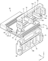
- FIG. 1 is a perspective view illustrating a connector according to a first embodiment.
- FIG. 2 is an elevation view illustrating the connector.
- FIG. 3 is a cross-sectional view taken along line A-A in FIG. 2 .
- FIG. 4 is an enlarged cross-sectional view illustrating a front section of the connector from which an outer housing is detached.
- FIG. 5 is a perspective view illustrating an inner housing.
- FIG. 6 is a perspective view illustrating a holding member when a pair of cover members is open.
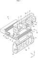
- FIG. 7 is a perspective view illustrating the inner housing where terminals are arranged and the holding member is provisionally fit.
- FIG. 8 is an elevation view illustrating the inner housing where the terminals are arranged and the holding member is provisionally fit.
- FIG. 9 is a cross-sectional view illustrating the inner housing where the terminals are arranged and the holding member is provisionally fit.
- FIG. 10 is a side view illustrating the inner housing where the holding member is provisionally fit and the wires are inserted.
- FIG. 11 is an enlarged cross-sectional view illustrating the inner housing where the holding member is provisionally fit and a jig is pressed to a jig receiver of a pressing member.
- FIG. 12 is an enlarged cross-sectional view illustrating the inner housing where the holding member is provisionally fit and pressing portions of the pressing member press holding portions of a terminal body section and a conductive member is sandwiched by the holding portions.
- FIG. 13 is a side view illustrating the inner housing where the holding member is fit.
- FIG. 14 is a cross-sectional view illustrating the inner housing where the holding member is fit.
- FIGS. 1 to 14 A first embodiment will be described with reference to FIGS. 1 to 14 .
- a connector 10 in this embodiment is mounted in a vehicle such as an automobile and is to be fit to a target connector that is connected to ends of wires or a device.
- an X-direction corresponds to a frontward direction
- a Y-direction corresponds to a leftward direction
- a Z-direction corresponds to an upward direction.
- the connector 10 includes terminals 20 that are connected to wires 11 , a housing 40 including an inner housing 41 and an outer housing 50 , and a holding member 60 that is to be mounted in the housing 40 and keeps a position of the terminals 20 .
- the wires 11 include conductive members 12 made of copper, copper alloy, aluminum, aluminum alloy, or other material and insulating covers 13 that surround and cover the respective conductive members 12 .
- the terminal 20 includes a terminal body portion 21 and a pressing member 30 that is a different component from the terminal body portion 21 .
- the terminal body portion 21 is a female terminal made of metal such as copper, copper alloy, aluminum, aluminum alloy, or other materials.
- the terminal body portion 21 includes a box portion 22 and an upper and lower pair of a holding portion 26 A and a holding portion 26 B.
- the box portion 22 has a square cylindrical shape and an elastic contact piece (not illustrated) that is to be connected to a target male terminal is arranged in the box portion 22 .
- the pair of holding portions 26 A, 26 B is disposed continuously from a rear portion of the box portion 22 and sandwiches the conductive member 12 of the wire 11 .
- the box portion 22 has a hole 23 in an upper portion (an outer surface of the inner housing 41 ) thereof and in a middle portion with respect to a front-rear direction.
- a distal end 12 A of the conductive member 12 can be seen from the outer surface side of the inner housing 41 through a space in the hole 23 of the box portion 22 .
- the pair of holding portions 26 A, 26 B is a pair of holding pieces and the holding portions 26 A and 26 B extend rearward from rear end portions of an upper wall and a lower wall of the box portion 22 , respectively, so as to form a rectangular plate shape.
- the upper (one) holding portion 26 A includes a thick portion 27 and a thin portion 28 that is thinner than the thick portion 27 and is on a rear side of the thick portion 27 .
- the lower (another) holding portion 26 B includes the thick portion 27 and the thin portion 28 that is thinner than the thick portion 27 and is on a front side of the thick portion 27 .
- a step is between the thick portion 27 and the thin portion 28 and connects the thick portion 27 and the thin portion 28 in a step-like form.
- Each of the holding portions 26 A, 26 B has serrations on the opposing surfaces and the serrations extend in form of grooves.
- Each of the holding portions 26 A, 26 B includes a deformed portion 24 at a basal end side thereof and the deformed portion 24 is formed with plastic deformation or elastic deformation when being pressed by the pressing member 30 .
- the pressing member 30 is made of metal such as copper, copper alloy, aluminum, aluminum alloy, or other materials or made of hard synthetic resin and is formed in a square cylindrical shape that can receive the rear portion of the terminal body portion 21 therein.
- the pressing member 30 includes an upper and lower pair of pressing portions 31 A, 31 B in a rear portion thereof and the pressing portions 31 A, 31 B are for pressing the pair of holding portions 26 A, 26 B.
- the pair of pressing portions 31 A, 31 B are formed by bending an upper wall 30 A and a lower wall 30 B of the pressing member 30 inwardly.
- the pressing portions 31 A, 31 B are formed to extend in an area corresponding to a length of the holding portions 26 A, 26 B with respect to the front-rear direction such that a distance between the upper wall 30 A and the lower wall 30 B is small in the area.
- the pressing member 30 includes a protrusion 33 on an upper surface of a top end portion thereof.
- the protrusion 33 protrudes upward and has a rectangular parallelepiped shape.
- the protrusion 33 extends over an entire width of the upper wall 30 A of the pressing member 30 .
- the protrusion 33 has a step portion that protrudes from the upper surface of the upper wall 30 A and the step portion is a jig receiver 33 A that can receive a jig J.
- the terminal body portion 21 and the pressing member 30 are made by punching and bending a metal plate with a pressing device.
- the housing 40 includes the inner housing 41 in which the terminals 20 are arranged and that is made of synthetic resin and the outer housing 50 that is fit to the inner housing 41 and made of synthetic resin.
- the inner housing 41 has a flat rectangular parallelepiped shape and includes terminal housing chambers 42 that are arranged in a vertical direction and a right-left direction.
- the terminal housing chambers 42 on an upper level and those on a lower level are arranged in a zig-zag form.
- the terminal housing chambers 42 on the lower level are arranged such that a middle (a center axis) of the terminal housing chamber 42 on the lower level with respect to the width direction is at a middle between the adjacent terminal housing chambers 42 on the upper level.
- Each of the terminal housing chambers 42 includes no ceiling wall 43 in the rear portion thereof and is open such that the terminal 20 is exposed through the opening to the outside of the inner housing 41 .
- the ceiling wall 43 includes a front stopper 44 in a rear end portion thereof.
- the front stopper 44 extends rearward.
- the front stopper 44 includes a recess portion 44 A on a lower surface thereof (an inner surface of the terminal housing chamber 42 ).
- the protrusion 33 of the pressing member 30 which is a front portion of the pressing member 30 , is in contact with and stopped at the recess portion 44 A.
- the terminal body portion 21 and the pressing member 30 are inserted through the space in the rear portion of the ceiling wall 32 of the inner housing 41 and arranged on a bottom surface of the terminal housing chamber 42 .
- each terminal housing chamber 42 has a sliding portion 42 A on an edge portion of an outer surface of the side wall thereof.
- Upper and lower opposing walls 65 A, 65 B of the holding member 60 can slide along the sliding portions 42 A.
- the sliding portion 42 A includes a front stopper 42 B that forms a step at a front end of the sliding portion 42 A.
- the front stoppers 42 B are to be contacted with front ends of the opposing walls 65 A, 65 B of the holding member 60 .
- the inner housing 41 includes terminal insertion holes 46 in the front wall thereof and the male terminals of the target connector, which is not illustrated, are to be inserted in the terminal insertion holes 46 .
- the inner housing 41 has recessed portions 41 A on outer surfaces of side walls thereof, respectively.
- the recessed portions 41 A are included in rear portions of the respective side walls and recessed inwardly.
- a fitting stopper 48 and a provisional fitting stopper 47 are arranged in the front-rear direction on the recessed portion 41 A and project from the recessed portion 41 A.
- Each of the provisional fitting stopper 47 and the fitting stopper 48 includes a front portion that projects in a step-like form and a rear portion that includes a sloped surface and reduces its projection dimension.
- the outer housing 50 includes a rectangular parallelepiped portion 51 and a front wall 55 .
- the rectangular parallelepiped portion 51 has a rectangular parallelepiped shape and can receive the inner housing 41 therein from the rear side.
- the front wall 55 closes a front side of the rectangular parallelepiped portion 51 .
- the front wall 55 includes terminal insertion holes 56 where the male terminals of the target connector are inserted.
- the rectangular parallelepiped portion 51 includes a lock arm 52 that locks fitting of the outer housing 50 and the target connector housing.
- the lock arm 52 includes a lock projection 53 that is to be fit to the target connector housing in a normal fitting state.
- the rectangular parallelepiped portion 51 includes flange portions 54 that project outwardly from the rear edge portion thereof.
- the rectangular parallelepiped portion 51 includes a separation restricting member, which is not illustrated, on the inner surface thereof.
- the separation restricting member is fit to the outer surface of the inner housing 41 to keep the fitting state where the inner housing 41 is fit in the rectangular parallelepiped portion 51 .
- the holding member 60 is made of insulating synthetic resin and, as illustrated in FIGS. 3 and 6 , includes a body member 61 and a pair of cover members 74 A, 74 B.
- the body member 61 includes terminal insertion holes 63 through which the wires 11 are inserted and has a flat rectangular parallelepiped shape.
- the cover members 74 A, 74 B are connected to a rear portion of the body member 61 via hinge portions 73 so as to be pivoted around the hinge portions 73 .
- the hinge portions 73 are formed in a thin belt-like shape and can be deformed to be warped.
- the body member 61 includes the opposing walls 65 A, 65 B that project frontward in the front end portion thereof.
- the body member 61 includes a right and left pair of side walls 61 A that connect the edges of the pair of opposing walls 65 A, 65 B and a pair of fitting frames 72 that extend frontward than the respective side walls 61 A.
- the body member 61 includes the terminal insertion holes 63 through which the wires 11 are inserted and the terminal insertion holes 63 are arranged in the vertical direction and the right-left direction.
- the terminal insertion holes 63 on an upper level and those on a lower level are arranged in a zig-zag form.
- the terminal insertion holes 63 on the lower level are arranged such that a middle (a center axis) of the terminal insertion hole 63 on the lower level with respect to the width direction is on a middle between the adjacent terminal insertion holes 63 on the upper level.
- the pair of opposing walls 65 A, 65 B are disposed to be able to slide along the sliding portions 42 A of the inner housing 40 . As illustrated in FIG. 4 , the front edges of the opposing walls 65 A, 65 B are restricting portions 65 C that are contacted with the front stoppers 42 B to restrict the body member 61 from moving frontward.
- the pair of opposing walls 65 A, 65 B includes projected portions 66 on the inner surfaces thereof and the projected portions 66 extend in the front-rear direction and are arranged in the right-left direction.
- the projected portions 66 are formed by increasing the thickness of the opposing walls 65 A, 65 B corresponding to the respective terminals 20 and an distal end portion of each projected portion 66 is sloped such that the thickness is reduced as it extends toward the distal end thereof.
- a rear end portion of the projected portion 66 includes a contact portion 67 protruding downward in a step-like form and is continuous to the terminal insertion hole 63 via the contact portion 67 .
- the contact portion 67 comes in contact with a rear end of the upper wall 30 A of the pressing member 30 .
- the pressing portions 31 A, 31 B of the pressing member 30 are positioned in a correct position so as to hold the holding portions 26 A, 26 B of the terminal body portion 21 .
- a projection piece 68 extends frontward from a portion of the opposing wall 65 B that is between the opposing walls 65 A and 65 B and continuous from a bottom surface of the terminal insertion hole 63 .
- the projection piece 68 comes in contact with the bottom surface of the terminal housing chamber 42 of the inner housing 41 .
- the body member 61 includes a disposing portion 70 extending from a rear portion thereof and the wires 11 are disposed on both surfaces of the disposing portion 70 .
- the disposing portion 70 has wire routing grooves 71 on upper and lower surfaces thereof.
- the wire routing grooves 71 form a wave shape that extends in the right-left direction to follow outer peripheral surfaces of the wires 11 .
- the wire routing grooves 71 are continuous rearward from the respective terminal insertion holes 63 and are arranged in a zig-zag form on the upper and lower surfaces of the disposing portion 70 .
- a middle (a center axis) of the wire routing groove 71 on the lower surface of the disposing portion 70 with respect to the width direction is on a middle between the adjacent wire routing grooves 71 on the upper surface of the disposing portion 70 .
- the pair of fitting frames 72 can be deformed to be warped with respect to the right-left direction and has a rectangular fitting hole 72 A therethrough.
- the provisional fitting stopper 47 or the fitting stopper 48 is stopped at a hole edge of the fitting hole 72 A.
- the pair of cover members 74 A, 74 B includes wire pressing portions 75 that project toward the wires 11 .
- the wire pressing portions 75 press the wires 11 that are disposed on the wire routing grooves 71 on the both surfaces of the disposing portion 70 .
- the wire pressing portion 75 projects to be formed in a tapered shape and extends over an entire width in the right-left direction.
- One cover member 74 A includes cover fitting pieces 76 and a pair of through holes 77 , which are slits.
- the cover fitting pieces 76 can be deformed to be warped and fit to the other cover member 74 B.
- the cover fitting piece 76 includes a fitting stopper 76 A at a distal end thereof.
- a tying band 82 (refer FIG.
- the other cover member 74 B includes receivers 78 where the respective fitting stoppers 76 A are fit.
- the one cover member 74 A includes cover fitting portions 79 extending from side wall surfaces thereof.
- the cover fitting portion 79 is formed in a frame shape and can be deformed to be warped.
- the other cover member 74 B includes cover fitting stoppers 80 projecting outwardly from outer wall surfaces thereof. The cover fitting stoppers 80 are fit in the respective cover fitting portions 79 .
- the cover fitting portion 79 When coming in contact with the cover fitting stopper 80 , the cover fitting portion 79 is deformed and warped and thereafter, the cover fitting portion 79 restores its original shape and stopped at a hole edge of a cover fitting hole 79 A of the cover fitting portion 79 . Thus, the pair of cover members 74 A, 74 B are maintained in a closed state.
- the pressing member 30 is fit to the rear end portion of the terminal body portion 21 of the terminal 20 and the terminal 20 is set in the terminal housing chamber 42 of the inner housing 41 .
- the holding member 60 is provisionally fit to the inner housing 41 by fitting the fitting frames 72 of the holding member 60 to the provisional fitting stoppers 47 of the inner housing 41 ( FIG. 10 ).
- the covers 13 are removed from the end portions of the wires 11 such that the conductive members 12 are exposed therefrom.
- the obtained wires 11 are inserted in the terminal insertion holes 63 of the holding member 60 and through the space between the pressing portions 31 A and 31 B and between the holding portions 26 A and 26 B.
- an operator inserts the wires 11 such that the distal ends 12 A of the conductive members 12 of the wires 11 reach the holes 23 while checking and seeing the distal ends 12 A of the conductive members 12 through spaces of the holes 23 and from an upper side of the inner housing 41 .
- the operator puts the jig J on the jig receiver 33 A of the protrusion 33 of the pressing member 30 and slides the pressing member 30 frontward with respect to the terminal body portion 21 .
- the terminal body portion 21 is deformed and the deformed portions 24 are formed and the pair of pressing portions 31 A, 31 B sandwich and press the pair of holding portions 26 A, 26 B and the pair of holding portions 26 A, 26 B hold the conductive member 12 of the wire 11 .
- the holding member 60 is moved frontward with respect to the inner housing 41 .
- the fitting between the provisional fitting stopper 47 and the holding member 60 is released and the fitting frames 72 that are in contact with the fitting stoppers 48 are deformed and warped. Accordingly, the fitting frames 72 are fit to the fitting stoppers 48 and become in a fitting state.
- the wires 11 are tied up and the tape 81 is wound around the wires 11 with using a space provided by opening the pair of cover members 74 A, 74 B ( FIGS. 13, 14 ).
- the one cover member 74 A is moved to be closed and the tying band 82 is inserted through the through holes 77 and the wires 11 wrapped with the tape 81 are tied up with the tying band 82 .
- the other cover member 74 B is moved to be closed and the cover fitting portions 79 and the cover fitting pieces 76 of the one cover member 74 A are fit to the cover fitting stoppers 80 and the receivers 78 of the other cover member 74 B (see FIGS. 1 and 7 ).
- the outer housing 50 is mounted on the inner housing 41 from the front side and the connector 10 is obtained.
- the connector 10 includes the terminals 20 that are contacted with the conductive members 12 of the wires 11 , the housing 40 in which the terminals 20 are arranged, and the holding member 60 that is mounted to the housing 40 and contacted with the terminals 20 to keep the positions of the terminals 20 .
- One of the terminals 20 and the housing 40 includes the pressing portions 31 A, 31 B that press the conductive member 12 in a direction such that the conductive member 12 comes in contact with the terminal 20 .
- the pressing portions 31 A, 31 B press the conductive member 12 in a direction such that the conductive member 12 comes in contact with the terminal 20 after the conductive member 12 of the wire 11 is disposed on the terminal 20 .
- the wires 11 are connected to the terminals 20 . Therefore, compared to a configuration in which the terminals are inserted in the housing after the terminals are connected to the ends of the wires 11 by crimping, the problems such as bending or warping of the wires 11 are less likely to be caused even with the downsized connector 10 and the downsized terminals 20 .
- the connector 10 described before can be downsized while restricting the occurrence of the bending or warping of the wires.
- connection errors may occur between the terminals 20 and the wires 11 due to the wrong positioning of the pressing portions 31 A, 31 B with respect to the conductive member 12 since the connector 10 is configured such that the pressing portions 31 A, 31 B press the conductive member 12 in a direction such that the conductive member 12 comes in contact with the terminal 20 to connect the conductive member 12 to the terminal 20 .
- the connection errors since the holding member 60 that is to be mounted in the housing 40 comes in contact with the terminals 20 to keep the position of the terminals 20 , the connection errors that may be caused between the terminals 20 and the wires 11 due to the wrong positioning of the pressing portions 31 A, 31 B with respect to the conductive member 12 are less likely to be caused.
- the terminal 20 includes the holding portions 26 A, 26 B and the pressing portions 31 A, 31 B that are separate components from the holding portions 26 A, 26 B.
- the holding portions 26 A, 26 B sandwich the conductive member 12 while being in contact with the conductive member 12 .
- the wires 11 can be connected to the terminals 20 by moving the holding portions 26 A, 26 B and the pressing portions 31 A, 31 B relatively each other after setting the holding portions 26 A, 26 B and the pressing portions 31 A, 31 B in the housing 40 . Therefore, the bending or warping of the wires 11 can be restricted in a configuration including the downsized connector 10 and the downsized terminals 20 .
- the pressing member 30 including the pressing portions 31 A, 31 B is sandwiched between the housing 40 and the holding member 60 and positioned.
- the holding portions 26 A, 26 B can keep holding the conductive member 12 of the wire 11 therebetween via the pressing member 30 . This can simplify the configuration of the connector 10 .
- One of the housing 40 and the holding member 60 includes the fitting stopper 48 and the provisional fitting stopper 47 .
- the fitting stopper 48 is fit to another one of the housing 40 and the holding member 60 while fixing the position of the holding portions 26 A, 26 B and the pressing portions 31 A, 31 B.
- the provisional fitting stopper 47 is provisionally fit to the other one of the housing 40 and the holding member 60 while not fixing the position of the holding portions 26 A, 26 B and the pressing portions 31 A, 31 B.
- the housing 40 and the holding member 60 that are provisionally fit each other can be made in the fitting state. This can simplify the fitting operation of the connector 10 .
- One of the terminal body portion 21 and the pressing member 30 includes the jig receiver 33 A where the jig J can be contacted with pressure while the holding member 60 and the housing 40 being provisionally fit each other.
- the jig receiver 33 A that receives the jig J can relatively move the terminal body portion 21 and the pressing member 30 with sliding.
- the holding member 60 includes the body member 61 , the cover members 74 A, 74 B, and the disposing portion 70 .
- the body member 61 is to be in contact with at least one of the terminal body portion 21 and the pressing member 30 .
- the cover members 74 A, 74 B are connected to the body member 61 via the hinge portions 73 so as to be pivoted around the hinge portions 73 and cover the wires 11 .
- the disposing portion 70 protrudes from the body member 61 toward the cover members 74 A, 74 B and the wires 11 are disposed on the disposing portion 70 .
- the cover members 74 A, 74 B include the wire pressing portions 75 , respectively, that press the wires 11 disposed on the disposing portion 70 toward the disposing portion 70 .
- the wire pressing portions 75 press and hold the wire 11 . This reduces stress that may be caused in a connection portion of the wire 11 and the terminal 20 .
- the above embodiment includes the inner housing 41 and the outer housing 50 .
- the embodiment is not limited to the configuration.
- one unitary housing may integrally include an inner housing and an outer housing or the housing may not include the outer housing 50 and include only the inner housing 41 .
- the holding member 60 is configured to be in contact with the pressing member 30 and keep the position of the terminal body portion 21 via the pressing member 30 .
- the embodiment is not limited to the configuration and the holding member may be in contact with the terminal body portion 21 and keep the position of the terminal body portion 21 and the pressing member 30 .
- the terminal body portion 21 includes the box portion 22 that is to be connected to a target male terminal.
- the embodiment is not limited to the configuration and the pressing member may include the box portion 22 .
- the holding member 60 includes the cover members 74 A, 74 B but may not include the cover members 74 A, 74 B.
- the terminal 20 includes the pressing portions 31 A, 31 B that press the holding portions 26 A, 26 B.
- a housing that receives the terminal 20 may include a configuration that presses the holding portions 26 A, 26 B.
- the housing may include a configuration that comes directly in contact with the conductive member 12 to press the conductive member 12 toward the terminal.
Landscapes
- Connector Housings Or Holding Contact Members (AREA)
- Details Of Connecting Devices For Male And Female Coupling (AREA)
Abstract
Description
- 10: connector
- 11: wire
- 12: conductive member
- 13: cover
- 20: terminal
- 21: terminal body portion
- 23: hole
- 26A, 26B: holding portion
- 30: pressing member
- 31A, 31B: pressing portion
- 33A: jig receiver
- 40: housing
- 41: inner housing
- 42: terminal housing chamber
- 44: front stopper
- 47: provisional fitting stopper
- 48: fitting stopper
- 50: outer housing
- 60: holding member
- 61: body member
- 65A, 65B: opposing wall
- 66: projected portion
- 67: contact portion
- 68: projection piece
- 70: disposing portion
- 71: wire routing groove
- 72: fitting frame
- 72A: fitting hole
- 73: hinge portion
- 74A, 74B: cover member
- 75: wire pressing portion
- J: jig
Claims (8)
Applications Claiming Priority (4)
| Application Number | Priority Date | Filing Date | Title |
|---|---|---|---|
| JPJP2018-025370 | 2018-02-15 | ||
| JP2018-025370 | 2018-02-15 | ||
| JP2018025370A JP6763896B2 (en) | 2018-02-15 | 2018-02-15 | connector |
| PCT/JP2019/003070 WO2019159691A1 (en) | 2018-02-15 | 2019-01-30 | Connector |
Publications (2)
| Publication Number | Publication Date |
|---|---|
| US20210036460A1 US20210036460A1 (en) | 2021-02-04 |
| US11228141B2 true US11228141B2 (en) | 2022-01-18 |
Family
ID=67619313
Family Applications (1)
| Application Number | Title | Priority Date | Filing Date |
|---|---|---|---|
| US16/968,238 Active US11228141B2 (en) | 2018-02-15 | 2019-01-30 | Connector |
Country Status (4)
| Country | Link |
|---|---|
| US (1) | US11228141B2 (en) |
| JP (1) | JP6763896B2 (en) |
| CN (1) | CN111684664B (en) |
| WO (1) | WO2019159691A1 (en) |
Cited By (2)
| Publication number | Priority date | Publication date | Assignee | Title |
|---|---|---|---|---|
| US20220123486A1 (en) * | 2019-01-22 | 2022-04-21 | Yokowo Co., Ltd. | Connector |
| US20220200171A1 (en) * | 2019-04-17 | 2022-06-23 | Sumitomo Wiring Systems, Ltd. | Communication cable with connector and connector assembly |
Families Citing this family (7)
| Publication number | Priority date | Publication date | Assignee | Title |
|---|---|---|---|---|
| EP3799224B1 (en) * | 2019-09-27 | 2024-08-14 | TE Connectivity Germany GmbH | Housing for an electrical connector |
| JP2021197286A (en) * | 2020-06-15 | 2021-12-27 | 株式会社オートネットワーク技術研究所 | Electric wire holding member and connector structure |
| JP7447731B2 (en) | 2020-08-07 | 2024-03-12 | 住友電装株式会社 | connector |
| JP7474412B2 (en) * | 2020-08-27 | 2024-04-25 | 住友電装株式会社 | connector |
| USD1000397S1 (en) * | 2021-06-07 | 2023-10-03 | Molex, Llc | Retainer for electrical connector |
| JP2024176636A (en) * | 2023-06-09 | 2024-12-19 | 株式会社オートネットワーク技術研究所 | connector |
| CN119209050B (en) * | 2024-11-08 | 2025-03-28 | 浙江博穆精密电子有限公司 | Connector convenient to equipment |
Citations (18)
| Publication number | Priority date | Publication date | Assignee | Title |
|---|---|---|---|---|
| JPS4998795U (en) | 1972-12-16 | 1974-08-26 | ||
| US4413872A (en) * | 1981-05-11 | 1983-11-08 | Amp Incorporated | Preloaded electrical connector |
| US4721482A (en) * | 1986-02-18 | 1988-01-26 | Yazaki Corporation | Connector housing |
| US4753612A (en) * | 1986-07-21 | 1988-06-28 | Amp Incorporated | Double lock electrical connector |
| US4975076A (en) * | 1990-03-01 | 1990-12-04 | Molex Incorporated | Contact wiping electrical connector |
| US5037325A (en) * | 1990-10-05 | 1991-08-06 | Molex Incorporated | Panel mounted electrical connector |
| US5195907A (en) * | 1990-05-31 | 1993-03-23 | Joseph Urban | Tooless electrical connector and conductor cable for use therewith |
| US5328386A (en) * | 1993-06-08 | 1994-07-12 | Frantz Robert H | Wire organizer for ballast connector |
| US5516984A (en) * | 1992-10-07 | 1996-05-14 | The Whitaker Corporation | Electrical connector having improved strain relief |
| US5545054A (en) * | 1994-08-26 | 1996-08-13 | Molex Incorporated | Electrical connector with hinged cover |
| US5573421A (en) * | 1993-10-18 | 1996-11-12 | Reichle + De-Massari Ag | Conductor connecting apparatus for weak-current system |
| US5697819A (en) * | 1994-11-15 | 1997-12-16 | Yazaki Corporation | Connector with rear holder |
| US5756972A (en) * | 1994-10-25 | 1998-05-26 | Raychem Corporation | Hinged connector for heating cables of various sizes |
| US6186821B1 (en) * | 1998-05-20 | 2001-02-13 | Heyco Products, Inc. | Hermaphroditic cable connector |
| US6843682B2 (en) * | 2002-08-30 | 2005-01-18 | Smk Corporation | Plug |
| US7140905B2 (en) * | 2003-10-31 | 2006-11-28 | Leviton Manufacturing Co., Inc. | Quick wire connect angle plug |
| JP2015056209A (en) | 2013-09-10 | 2015-03-23 | ヒロセ電機株式会社 | Electrical connector terminal and electrical connector |
| JP2016009527A (en) | 2014-06-20 | 2016-01-18 | 矢崎総業株式会社 | connector |
Family Cites Families (4)
| Publication number | Priority date | Publication date | Assignee | Title |
|---|---|---|---|---|
| JP5282540B2 (en) * | 2008-11-21 | 2013-09-04 | 日立電線株式会社 | Male-female connection structure |
| JP5748335B2 (en) * | 2011-06-08 | 2015-07-15 | 日本航空電子工業株式会社 | connector |
| EP3128617A1 (en) * | 2015-08-04 | 2017-02-08 | Dubuis et Cie | Device for fixing an electrical connection terminal to a support |
| JP6643154B2 (en) * | 2016-03-10 | 2020-02-12 | ヒロセ電機株式会社 | Electrical connector for flat conductor |
-
2018
- 2018-02-15 JP JP2018025370A patent/JP6763896B2/en active Active
-
2019
- 2019-01-30 WO PCT/JP2019/003070 patent/WO2019159691A1/en not_active Ceased
- 2019-01-30 CN CN201980011894.5A patent/CN111684664B/en active Active
- 2019-01-30 US US16/968,238 patent/US11228141B2/en active Active
Patent Citations (18)
| Publication number | Priority date | Publication date | Assignee | Title |
|---|---|---|---|---|
| JPS4998795U (en) | 1972-12-16 | 1974-08-26 | ||
| US4413872A (en) * | 1981-05-11 | 1983-11-08 | Amp Incorporated | Preloaded electrical connector |
| US4721482A (en) * | 1986-02-18 | 1988-01-26 | Yazaki Corporation | Connector housing |
| US4753612A (en) * | 1986-07-21 | 1988-06-28 | Amp Incorporated | Double lock electrical connector |
| US4975076A (en) * | 1990-03-01 | 1990-12-04 | Molex Incorporated | Contact wiping electrical connector |
| US5195907A (en) * | 1990-05-31 | 1993-03-23 | Joseph Urban | Tooless electrical connector and conductor cable for use therewith |
| US5037325A (en) * | 1990-10-05 | 1991-08-06 | Molex Incorporated | Panel mounted electrical connector |
| US5516984A (en) * | 1992-10-07 | 1996-05-14 | The Whitaker Corporation | Electrical connector having improved strain relief |
| US5328386A (en) * | 1993-06-08 | 1994-07-12 | Frantz Robert H | Wire organizer for ballast connector |
| US5573421A (en) * | 1993-10-18 | 1996-11-12 | Reichle + De-Massari Ag | Conductor connecting apparatus for weak-current system |
| US5545054A (en) * | 1994-08-26 | 1996-08-13 | Molex Incorporated | Electrical connector with hinged cover |
| US5756972A (en) * | 1994-10-25 | 1998-05-26 | Raychem Corporation | Hinged connector for heating cables of various sizes |
| US5697819A (en) * | 1994-11-15 | 1997-12-16 | Yazaki Corporation | Connector with rear holder |
| US6186821B1 (en) * | 1998-05-20 | 2001-02-13 | Heyco Products, Inc. | Hermaphroditic cable connector |
| US6843682B2 (en) * | 2002-08-30 | 2005-01-18 | Smk Corporation | Plug |
| US7140905B2 (en) * | 2003-10-31 | 2006-11-28 | Leviton Manufacturing Co., Inc. | Quick wire connect angle plug |
| JP2015056209A (en) | 2013-09-10 | 2015-03-23 | ヒロセ電機株式会社 | Electrical connector terminal and electrical connector |
| JP2016009527A (en) | 2014-06-20 | 2016-01-18 | 矢崎総業株式会社 | connector |
Non-Patent Citations (2)
| Title |
|---|
| International Search Report issued in International Patent Application No. PCT/JP2019/003070, dated Mar. 19, 2019, together with an English translation thereof. |
| Written Opinion issued in International Patent Application No. PCT/JP2019/003070, dated Mar. 19, 2019, together with an English translation thereof. |
Cited By (2)
| Publication number | Priority date | Publication date | Assignee | Title |
|---|---|---|---|---|
| US20220123486A1 (en) * | 2019-01-22 | 2022-04-21 | Yokowo Co., Ltd. | Connector |
| US20220200171A1 (en) * | 2019-04-17 | 2022-06-23 | Sumitomo Wiring Systems, Ltd. | Communication cable with connector and connector assembly |
Also Published As
| Publication number | Publication date |
|---|---|
| WO2019159691A1 (en) | 2019-08-22 |
| CN111684664B (en) | 2022-04-29 |
| JP6763896B2 (en) | 2020-09-30 |
| CN111684664A (en) | 2020-09-18 |
| US20210036460A1 (en) | 2021-02-04 |
| JP2019145209A (en) | 2019-08-29 |
Similar Documents
| Publication | Publication Date | Title |
|---|---|---|
| US11228141B2 (en) | Connector | |
| TWI387167B (en) | L-type coaxial connector | |
| US10680378B2 (en) | Wire cover and connector | |
| US9972936B2 (en) | Connector member and connector | |
| WO2012023533A1 (en) | Connector | |
| US10622751B2 (en) | Connector | |
| JP7001979B2 (en) | Shield terminal | |
| US10756478B2 (en) | Terminal and method of connecting electric wire to terminal | |
| US20250105554A1 (en) | Connector | |
| US20230238729A1 (en) | Connector | |
| JP7339018B2 (en) | IDC terminals, electric wires with terminals, and connectors | |
| US12142866B2 (en) | Terminal fitting and connector | |
| US12592348B2 (en) | Terminal module | |
| JP2020205231A (en) | connector | |
| US12119586B2 (en) | Connector | |
| US10804625B2 (en) | Terminal, method of connecting electric wire to terminal, and jig | |
| US20250105555A1 (en) | Connector | |
| US10892582B2 (en) | Connector with upper and lower covers | |
| US20250357692A1 (en) | Terminal device | |
| JP2025035563A (en) | Clamping type | |
| US20240297453A1 (en) | Terminal | |
| US20260018812A1 (en) | Terminal fitting | |
| US20240266771A1 (en) | Terminal | |
| JP3138221B2 (en) | Connector and connector assembly method | |
| WO2022190780A1 (en) | Connector |
Legal Events
| Date | Code | Title | Description |
|---|---|---|---|
| AS | Assignment |
Owner name: SUMITOMO ELECTRIC INDUSTRIES, LTD., JAPAN Free format text: ASSIGNMENT OF ASSIGNORS INTEREST;ASSIGNORS:MIYAMURA, TETSUYA;TABATA, MASAAKI;OMORI, YASUO;AND OTHERS;SIGNING DATES FROM 20200619 TO 20200626;REEL/FRAME:053431/0460 Owner name: TOYOTA JIDOSHA KABUSHIKI KAISHA, JAPAN Free format text: ASSIGNMENT OF ASSIGNORS INTEREST;ASSIGNORS:MIYAMURA, TETSUYA;TABATA, MASAAKI;OMORI, YASUO;AND OTHERS;SIGNING DATES FROM 20200619 TO 20200626;REEL/FRAME:053431/0460 Owner name: AUTONETWORKS TECHNOLOGIES, LTD., JAPAN Free format text: ASSIGNMENT OF ASSIGNORS INTEREST;ASSIGNORS:MIYAMURA, TETSUYA;TABATA, MASAAKI;OMORI, YASUO;AND OTHERS;SIGNING DATES FROM 20200619 TO 20200626;REEL/FRAME:053431/0460 Owner name: SUMITOMO WIRING SYSTEMS, LTD., JAPAN Free format text: ASSIGNMENT OF ASSIGNORS INTEREST;ASSIGNORS:MIYAMURA, TETSUYA;TABATA, MASAAKI;OMORI, YASUO;AND OTHERS;SIGNING DATES FROM 20200619 TO 20200626;REEL/FRAME:053431/0460 |
|
| FEPP | Fee payment procedure |
Free format text: ENTITY STATUS SET TO UNDISCOUNTED (ORIGINAL EVENT CODE: BIG.); ENTITY STATUS OF PATENT OWNER: LARGE ENTITY |
|
| STPP | Information on status: patent application and granting procedure in general |
Free format text: APPLICATION DISPATCHED FROM PREEXAM, NOT YET DOCKETED |
|
| STPP | Information on status: patent application and granting procedure in general |
Free format text: DOCKETED NEW CASE - READY FOR EXAMINATION |
|
| STPP | Information on status: patent application and granting procedure in general |
Free format text: NON FINAL ACTION MAILED |
|
| STPP | Information on status: patent application and granting procedure in general |
Free format text: RESPONSE TO NON-FINAL OFFICE ACTION ENTERED AND FORWARDED TO EXAMINER |
|
| STPP | Information on status: patent application and granting procedure in general |
Free format text: NOTICE OF ALLOWANCE MAILED -- APPLICATION RECEIVED IN OFFICE OF PUBLICATIONS |
|
| STPP | Information on status: patent application and granting procedure in general |
Free format text: PUBLICATIONS -- ISSUE FEE PAYMENT VERIFIED |
|
| STCF | Information on status: patent grant |
Free format text: PATENTED CASE |
|
| MAFP | Maintenance fee payment |
Free format text: PAYMENT OF MAINTENANCE FEE, 4TH YEAR, LARGE ENTITY (ORIGINAL EVENT CODE: M1551); ENTITY STATUS OF PATENT OWNER: LARGE ENTITY Year of fee payment: 4 |