US11228050B2 - Multi-metallic electro-catalyst for alkaline exchange membrane fuel cells and method of making same - Google Patents
Multi-metallic electro-catalyst for alkaline exchange membrane fuel cells and method of making same Download PDFInfo
- Publication number
- US11228050B2 US11228050B2 US16/636,064 US201816636064A US11228050B2 US 11228050 B2 US11228050 B2 US 11228050B2 US 201816636064 A US201816636064 A US 201816636064A US 11228050 B2 US11228050 B2 US 11228050B2
- Authority
- US
- United States
- Prior art keywords
- catalyst
- nanoparticles
- nanoparticle
- catalyst layer
- exchange membrane
- Prior art date
- Legal status (The legal status is an assumption and is not a legal conclusion. Google has not performed a legal analysis and makes no representation as to the accuracy of the status listed.)
- Active, expires
Links
Images


Classifications
-
- H—ELECTRICITY
- H01—ELECTRIC ELEMENTS
- H01M—PROCESSES OR MEANS, e.g. BATTERIES, FOR THE DIRECT CONVERSION OF CHEMICAL ENERGY INTO ELECTRICAL ENERGY
- H01M4/00—Electrodes
- H01M4/86—Inert electrodes with catalytic activity, e.g. for fuel cells
- H01M4/90—Selection of catalytic material
- H01M4/92—Metals of platinum group
-
- H—ELECTRICITY
- H01—ELECTRIC ELEMENTS
- H01M—PROCESSES OR MEANS, e.g. BATTERIES, FOR THE DIRECT CONVERSION OF CHEMICAL ENERGY INTO ELECTRICAL ENERGY
- H01M8/00—Fuel cells; Manufacture thereof
- H01M8/10—Fuel cells with solid electrolytes
- H01M8/1004—Fuel cells with solid electrolytes characterised by membrane-electrode assemblies [MEA]
-
- H—ELECTRICITY
- H01—ELECTRIC ELEMENTS
- H01M—PROCESSES OR MEANS, e.g. BATTERIES, FOR THE DIRECT CONVERSION OF CHEMICAL ENERGY INTO ELECTRICAL ENERGY
- H01M4/00—Electrodes
- H01M4/86—Inert electrodes with catalytic activity, e.g. for fuel cells
- H01M4/8663—Selection of inactive substances as ingredients for catalytic active masses, e.g. binders, fillers
- H01M4/8668—Binders
-
- H—ELECTRICITY
- H01—ELECTRIC ELEMENTS
- H01M—PROCESSES OR MEANS, e.g. BATTERIES, FOR THE DIRECT CONVERSION OF CHEMICAL ENERGY INTO ELECTRICAL ENERGY
- H01M4/00—Electrodes
- H01M4/86—Inert electrodes with catalytic activity, e.g. for fuel cells
- H01M4/88—Processes of manufacture
- H01M4/8878—Treatment steps after deposition of the catalytic active composition or after shaping of the electrode being free-standing body
- H01M4/8892—Impregnation or coating of the catalyst layer, e.g. by an ionomer
-
- H—ELECTRICITY
- H01—ELECTRIC ELEMENTS
- H01M—PROCESSES OR MEANS, e.g. BATTERIES, FOR THE DIRECT CONVERSION OF CHEMICAL ENERGY INTO ELECTRICAL ENERGY
- H01M4/00—Electrodes
- H01M4/86—Inert electrodes with catalytic activity, e.g. for fuel cells
- H01M4/90—Selection of catalytic material
- H01M4/9016—Oxides, hydroxides or oxygenated metallic salts
-
- H—ELECTRICITY
- H01—ELECTRIC ELEMENTS
- H01M—PROCESSES OR MEANS, e.g. BATTERIES, FOR THE DIRECT CONVERSION OF CHEMICAL ENERGY INTO ELECTRICAL ENERGY
- H01M4/00—Electrodes
- H01M4/86—Inert electrodes with catalytic activity, e.g. for fuel cells
- H01M4/90—Selection of catalytic material
- H01M4/92—Metals of platinum group
- H01M4/921—Alloys or mixtures with metallic elements
-
- H—ELECTRICITY
- H01—ELECTRIC ELEMENTS
- H01M—PROCESSES OR MEANS, e.g. BATTERIES, FOR THE DIRECT CONVERSION OF CHEMICAL ENERGY INTO ELECTRICAL ENERGY
- H01M4/00—Electrodes
- H01M4/86—Inert electrodes with catalytic activity, e.g. for fuel cells
- H01M4/90—Selection of catalytic material
- H01M4/92—Metals of platinum group
- H01M4/925—Metals of platinum group supported on carriers, e.g. powder carriers
- H01M4/926—Metals of platinum group supported on carriers, e.g. powder carriers on carbon or graphite
-
- H—ELECTRICITY
- H01—ELECTRIC ELEMENTS
- H01M—PROCESSES OR MEANS, e.g. BATTERIES, FOR THE DIRECT CONVERSION OF CHEMICAL ENERGY INTO ELECTRICAL ENERGY
- H01M8/00—Fuel cells; Manufacture thereof
- H01M8/08—Fuel cells with aqueous electrolytes
- H01M8/083—Alkaline fuel cells
-
- H—ELECTRICITY
- H01—ELECTRIC ELEMENTS
- H01M—PROCESSES OR MEANS, e.g. BATTERIES, FOR THE DIRECT CONVERSION OF CHEMICAL ENERGY INTO ELECTRICAL ENERGY
- H01M8/00—Fuel cells; Manufacture thereof
- H01M8/10—Fuel cells with solid electrolytes
- H01M8/1016—Fuel cells with solid electrolytes characterised by the electrolyte material
- H01M8/1018—Polymeric electrolyte materials
-
- H—ELECTRICITY
- H01—ELECTRIC ELEMENTS
- H01M—PROCESSES OR MEANS, e.g. BATTERIES, FOR THE DIRECT CONVERSION OF CHEMICAL ENERGY INTO ELECTRICAL ENERGY
- H01M8/00—Fuel cells; Manufacture thereof
- H01M8/10—Fuel cells with solid electrolytes
- H01M2008/1095—Fuel cells with polymeric electrolytes
-
- Y—GENERAL TAGGING OF NEW TECHNOLOGICAL DEVELOPMENTS; GENERAL TAGGING OF CROSS-SECTIONAL TECHNOLOGIES SPANNING OVER SEVERAL SECTIONS OF THE IPC; TECHNICAL SUBJECTS COVERED BY FORMER USPC CROSS-REFERENCE ART COLLECTIONS [XRACs] AND DIGESTS
- Y02—TECHNOLOGIES OR APPLICATIONS FOR MITIGATION OR ADAPTATION AGAINST CLIMATE CHANGE
- Y02E—REDUCTION OF GREENHOUSE GAS [GHG] EMISSIONS, RELATED TO ENERGY GENERATION, TRANSMISSION OR DISTRIBUTION
- Y02E60/00—Enabling technologies; Technologies with a potential or indirect contribution to GHG emissions mitigation
- Y02E60/30—Hydrogen technology
- Y02E60/50—Fuel cells
Definitions
- the invention is generally related to the field of alkaline exchange membrane fuel cells and more precisely to catalysts for alkaline exchange membrane fuel cells.
- Alkaline exchange membrane fuel cells are usually operated with hydrogen containing fuels having the lowest possible content of CO 2 . Research has proved that as little as 5 ppm of CO 2 can harm the performance of the fuel cell. In order to reduce the amount of CO 2 in the cell, complicated and sometime expensive CO 2 filtering systems are added before the fuel entrance to the fuel cell.
- anode catalysts for AEMFC include mostly Platinum (Pt) nanoparticles which are becoming inefficient when operating with CO 2 -containing fuel.
- the anode H 2 oxidation reaction (HOR) at Pt surfaces using bi-carbonate ions is slower (and thus less favored) in comparison to the HOR using pure H 2 (reaction (1)).
- the concentration of carbonate and/or bi-carbonate ions in the anode therefore increases with time relative to [OH—], and overall cell performance is therefore reduced. This reduces the ability to use cheaper fuels containing CO 2 (such as, reformed Methanol, Ethanol, etc.).
- Bi-carbonate and carbonate ions have lower diffusivity than OH ⁇ ion and therefore may travel inside the AEMFC at lower velocity than OH ⁇ , reducing the cell conductivity. Furthermore, bi-carbonate and carbonate ions accumulate at the AEMFC anode, at the expense of OH ions that are required for reaction. (1).
- Some aspects of the invention may be directed to a catalyst layer for anodes of Alkaline Exchange Membrane Fuel Cells (AEMFC).
- AEMFC Alkaline Exchange Membrane Fuel Cells
- Such catalyst layer may include catalyst nanoparticles and an ionomer.
- each catalyst nanoparticle may include one or more nanoparticles of catalytically active metal supported on at least one nanoparticle of a conductive compound, for example, crystalline RuO 2 .
- the diameter of the at least one nanoparticle of a conductive compound may be about order of magnitude larger than the diameter of the one or more nanoparticles of catalytically active metal.
- the catalytically active metal may be selected from a group consisting of: Pt, Pd, Ir, Ru and their alloys.
- the conductive compound may be selected from a group consisting of: crystalline metal oxides, crystalline RuO 2 , crystalline doped TiO 2 .
- each catalyst nanoparticle further comprises one or more catalytically non-active metallic nanoparticles.
- the one or more catalytically non-active metallic nanoparticles may be selected from a group consisting of: Ru, Ag, Ni, Fe.
- the catalyst nanoparticles may include between 2 wt. % to at most 20 wt. % of the catalytically active metal. In some embodiments, the size of the catalytically active metal nanoparticles is between 2-10 nm. In some embodiments, the catalyst layer may have at thickness of at most 25 micrometer. In some embodiments, the catalyst layer may include between 5-35 wt. % ionomer.
- Some additional aspects of the invention may be directed to a catalyst layer for anodes of Alkaline Exchange Membrane Fuel Cells (AEMFC).
- This catalyst layer may include catalyst nanoparticles having one or more nanoparticles of catalytically active metal supported on at least one Ru nanoparticle and an ionomer.
- the catalytically active metal may be selected from a group consisting of: Pt, Pd, Ir, Ru and their alloys.
- each catalyst nanoparticle may further include at least one nanoparticle of a conductive compound.
- the conductive compound may be selected from a group consisting of: metal oxides, crystalline RuO 2 , crystalline doped TiO 2 .
- the at least one Ru nanoparticle may have a diameter about one order of magnitude larger than the diameter of the one or more nanoparticles of catalytically active metal.
- the size of the catalytically active metal nanoparticles may be between 2-10 nm.
- the size of the catalytically active metal nanoparticles is between 2-10 nm.
- the catalyst layer may have at thickness of at most 25 micrometer.
- the catalyst layer may include between 5-35 wt. % ionomer.
- the Alkaline Exchange Membrane Fuel Cell may include an Alkaline Exchange Membrane, a cathode catalyst coated on a first side of the Alkaline Exchange Membrane; and an anode catalyst according to some embodiments of the invention.
- FIG. 1 is an illustration of an alkaline exchange membrane fuel cell according to some embodiments of the invention.
- FIG. 2 is an illustration of an anode catalyst layer for an alkaline exchange membrane fuel cell according to some embodiments of the invention
- FIGS. 3A and 3B are illustration of nanoparticles of an anode catalyst for an alkaline exchange membrane fuel cell according to some embodiments of the invention.
- FIG. 4 is an illustration of a nanoparticle of an anode catalyst for an alkaline exchange membrane fuel cell according to some embodiments of the invention.
- FIG. 5 is a high resolution transmission electron micrograph (lattice image) of a nanoparticle according to some embodiments of the invention.
- FIG. 6 is an X-Ray diffraction of a catalyst for an alkaline exchange membrane fuel cell according to some embodiments of the invention.
- FIGS. 7A-7C are graphs of Voltage vs. Current Density of alkaline exchange membrane fuel cells with Pt based anode catalyst and anode catalysts according to some embodiments of the invention.
- FIG. 8 is a graph of the performance over time of alkaline exchange membrane fuel cells having an anode catalyst according to some embodiments of the invention.
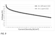
- FIG. 9 is a graph of Voltage vs. Current Density of alkaline exchange membrane fuel cells with Ir based anode catalyst according to some embodiments of the invention.
- Some aspects of the invention may be related to increasing the ability to use cheaper fuels containing CO 2 (such as reformed Methanol, Ethanol, etc.) in Alkaline Exchange Membrane Fuel Cells (AEMFC).
- AEMFC Alkaline Exchange Membrane Fuel Cells
- special catalysts have been developed. Such catalysts may enable to produce electrical current using reactions (4) and (5) disclosed above.
- the newly developed catalysts may further enhance reaction (1), thus improving the overall performance of the AEMFC.
- a catalytic layer for AEMFC may have to exhibit the following properties and performances.
- a commercial cost-effective catalytic layer one may like to minimize the amount of platinum group metals (PGM) due to their high costs.
- the catalyst layer may have to create electronic percolation using high electrical conducting material.
- the catalytic layer thickness may be selected as to avoid mass transport issues and keep low overall resistance. Materials selected to be included in the catalyst layer may be as little hydrophobic as possible in order to allow proper water transport.
- the catalytic layer may further include a sufficient amount of ionomer to allow ion and water transport and a sufficient amount of porosity to allow gas penetration. Accordingly, such catalyst layer may include a conductive hydrophilic support particles to support the minimal amount of costly active material (e.g., PGM) required.
- the commonly used carbon particles support is highly hydrophobic and has low tap density that may make the catalyst layer too thick.
- a catalyst according to some embodiments of the invention may include catalyst nanoparticles, in which each catalyst nanoparticle may include at least two different types of nanocrystals: catalytically active metallic nanocrystals supported, attached and/or carried on larger electrically conducting compound nanocrystals.
- catalytically active metallic nanocrystals may include metallic nanocrystals that catalytically activate the chemical reactions taking place on the surface of the anode and the cathode of the AEMFC, for example, reactions (1)-(5) disclosed herein above.
- the electrically conducting nanocrystals may be configured to increase the surface area of the catalytically active metallic nanocrystals.
- the catalyst may further include an ionomer holding the catalyst nanoparticle as a layer. The ionomer may be crosslinked or may not be crosslinked to the anion conducting membrane.
- An AEMFC 10 may include an anion conducting membrane 20 a cathode catalyst layer 30 coated on the cathode side of membrane 20 , a cathode gas diffusion layer (GDL) 40 , an anode catalyst layer 50 coated or attached to the anode side of membrane 20 and anode GDL 60 .
- Anion conducting membrane 20 may be any membrane configured to conduct anions such as OH ⁇ , CO 3 2 ⁇ and HCO 3 ⁇ .
- membrane 20 may include anions conducting solid polymer electrolyte that includes hydrocarbon backbone polymer, for example, Tokuyama AS4TM, Fumatech FAA-3TM, or aminated Poly Chloromethyl Styrene (also known as Poly Vinyl Benzyl Chloride) and the like.
- hydrocarbon backbone polymer for example, Tokuyama AS4TM, Fumatech FAA-3TM, or aminated Poly Chloromethyl Styrene (also known as Poly Vinyl Benzyl Chloride) and the like.
- Cathode catalyst layer 30 may include any suitable cathode catalyst metal, such as Ag with any suitable additives such as carbon, ionomer, etc.
- GDLs 40 and 60 may include porous material made from a dense array of carbon fibers (base e.g., on carbon paper, carbon cloth, carbon fiber or the like, with or without a micro porous layer (MPL). These GDLs may also provide an electrically conductive pathway for current collection. In some embodiments, GDLs 40 and 60 may allow passage for reactant transport and heat/water removal. GDLs 40 and 60 may further provide mechanical support to membrane 20 and protection of catalyst layers 30 and 50 from corrosion or erosion caused by flows or other factors.
- MPL micro porous layer
- Anode catalyst layer 50 may include catalyst nanoparticles 54 and an ionomer 58 .
- Ionomer 58 may include any ionomer suitable for carrying a catalyst in an AEMFC.
- ionomer 58 may include Tokuyama AS4, Fumatech FAA-3, or aminated Poly Chloromethyl Styrene (also known as Poly Vinyl Benzyl Chloride) and the like. Materials selected to be included in catalyst layer 50 may be as little hydrophobic as possible in order to allow proper water transport.
- Catalytic layer 50 may include a sufficient amount of ionomer 85 to allow ion and water transport and a sufficient amount of porosity to allow gas penetration.
- catalyst layer 50 may include between 5-35 wt. % ionomer.
- catalyst layer 50 may have a thickness of at most 25 micrometer.
- Catalyst nanoparticle 54 may include one or more nanoparticles 56 of catalytically active metal supported, carried and/or attached to at least one nanoparticle 55 of a conductive compound, as illustrated in FIG. 3A .
- catalytically active metal nanoparticles 56 may have a diameter of at least one order of magnitude smaller than conductive compound nanoparticle 55 diameter.
- each one of conductive compound nanoparticle 55 and catalytically active metal nanoparticles 56 may be either crystalline of non-crystalline.
- the size (e.g., average diameter) of catalytically active metal nanoparticles 55 may be between 2-10 nm and the size (e.g., average diameter) of conductive compound nanoparticles 56 may be between 20-100 nm.
- the catalytically active metal may be selected from a group consisting of: PGM, such as, Pt, Pd, Ir and their alloys.
- catalytically active metal nanoparticles 55 may include a nanocrystal of the catalytically active metal.
- the conductive compound may be selected to be as little hydrophobic as possible, as explained above.
- the conductive compound may be selected from a group consisting of: crystalline metal oxides such as, crystalline RuO 2 , crystalline doped TiO, Nb x O y , crystalline metal carbides, such as WC and the like.
- crystalline RuO 2 may include nano crystals of RuO 2 that may or may not include doping.
- conductive compound nanoparticles 56 may include a nanocrystal of the conductive compound.
- the catalyst nanoparticle 54 may further include one or more catalytically non-active metallic nanoparticles 57 , as illustrated in FIG. 3B .
- one or more catalytically non-active metallic nanoparticles 57 may be selected from a group consisting of: Ru, Ag, Ni, Fe nanoparticles.
- one or more of catalytically non-active metallic nanoparticles 57 may be a nanocrystal.
- the size of catalytically non-active metallic nanoparticle 57 may be between 10-50 nm, between 10-100 nm or more than 100 nm.
- Some aspects of the invention may be related to a catalyst layer for anodes of Alkaline Exchange Membrane Fuel Cells (AEMFC), such as layer 50 , that include catalyst nanoparticles 540 (illustrated in FIG. 4 ) and an ionomer, such as the ionomer 58 illustrated and discussed with respect to FIG. 2 .
- FIG. 4 is an illustration of catalyst nanoparticle 540 that may include one or more nanoparticles 56 of catalytically active metal supported, carried and/or attached on at least one Ru nanoparticle 545 .
- Catalytically active nanoparticles 56 included in nanoparticles 540 may be substantially the same as nanoparticles 56 included in catalyst nanoparticles 54 .
- Ru nanoparticle 545 may be crystalline.
- the size (e.g., average diameter) of Ru nanoparticle 545 may be at least one order of magnitude larger than catalytically active nanoparticles 56 .
- Catalysts nanoparticles were prepared using any known method.
- the catalyst nanoparticles may be prepared by reduction of a salt of the required metal(s), e.g. RuCl 3 .xH 2 O or similar, by the use of a suitable reducing agent such as sodium acetate, sodium or other borohydride, hydrazine, or any number of other available known reducing agents.
- a suitable reducing agent such as sodium acetate, sodium or other borohydride, hydrazine, or any number of other available known reducing agents.
- the precursor materials may be held in aqueous solution and heated under reflux conditions or hydrothermal conditions, or by heating by microwave or other direct radiation.
- the metal salt and the reducing agent can be pre-mixed or mixed after heating to a desired temperature.
- Blending of the reducing agent with the metal salt, possibly with additional treatment such as heating, may lead to the formation of nucleated metal clusters that develop with time into nanoparticles in the reaction mixture.
- the growth of these particles may be controlled by reaction time, temperature, and in some cases the presence of surface-active agents (surfactants) or other additives to moderate growth of the particles.
- the reaction mixture may be removed from the reaction conditions (e.g., cooled to room temperature and/or pressure) and the supernatant then separated from the particles. Additives and remaining reactants may be subsequently washed and/or burned away. Exposure to oxygen during the process may lead to the formation of metal oxide(s) together with or in place of, or as a part of, the metal particles. This can also typically be controlled to a certain degree.
- Another example for a method of preparing catalyst nanoparticles may include: depositing catalytic nanoparticles on the support particles by following a similar procedure but using a salt of the catalytic metal(s), with the same or different combinations of reducing agent(s) and surfactant(s), in the presence of pre-formed support particles.
- the catalytic particles may be prepared separately and later mixed mechanically by various means known in the art such as stirring, sonication and/or other homogenizing techniques applied to a co-dispersion, and/or by ball milling or other processing techniques.
- the two types of particles may be prepared in a single step where salts of both metals are present in the reaction mixture. Such a one-step process (mixing the salts of different metals together) could lead either to alloys of the various particles, separate particles of one species and another, or a mixture of those.
- the catalyst nanoparticles included: 15 weight (wt.)% Pt, 42.5 wt. % RuO2 and 42.5 wt. % Ru or 9 wt. % Pt, 45.5 wt. % RuO2 and 45.5 wt. % Ru.
- the catalysts nanoparticles were analyzed using HRTEM and XRD and added to an ionomer to form a catalytic layer of a solid electrolyte membrane. The performance of the new catalytic layer were tested during the operation of an AEMFC.
- FIG. 5 is a lattice image taken by a high resolution transmission electron microscope of a catalyst nanoparticle according to some embodiments of the invention.
- the image shows a small Pt crystal having a diameter of approximately 5 nm attached to a larger RuO 2 crystal having a dimeter of approximately 10 nm.
- FIG. 6 is an XRD spectrum taken from the catalyst according to some embodiments of the invention.
- the XRD maxima were identified as the typical maxima of crystalline Pt, Ru and RuO 2 .
- FIG. 7A shows graphs showing the voltage vs. the current density taken from an AEMFC that included the Pt anode catalyst when supplied with two types of fuels: a clean H 2 having less than 1 ppm CO 2 and H 2 with 100 ppm CO 2 .
- a clean H 2 having less than 1 ppm CO 2
- H 2 with 100 ppm CO 2 there is a loss of more than 10% in the voltage at high current densities (above 0.6 A/cm 3 ) when operating the cell with H 2 with 100 ppm CO 2 .
- FIG. 7B shows graphs showing the voltage vs. the current density taken from an AEMFC that included an anode catalyst according to some embodiments of the invention.
- the catalyst of FIG. 7B included 15 wt. % Pt, 42.5 wt. % RuO 2 and 42.5 wt. % Ru.
- FIG. 7C shows graphs showing the voltage vs. the current density taken from an AEMFC that included an anode catalyst according to some embodiments of the invention.
- the catalyst of FIG. 7C included 9 wt. % Pt, 45.5 wt. % RuO 2 and 45.5 wt. % Ru.
- the overall drop in voltage at higher current densities of the cell operating in both types of fuels is 20% less than the drop in the fuel cell of FIG. 7A operating with pure H 2 .
- a catalysts made according to embodiments of the invention may improve the performance of the fuel cell operating which any type of fuel in comparison to fuel cells known in the art.
- FIG. 8 shows the performance (in percentage; voltage, current or power) over time of a cell with a catalyst according to embodiments of the invention (the catalyst of FIG. 7B ) operating with fuels having 100 ppm and 1 ppm levels of CO 2 at the anode fuel stream.
- the performance drops by approximately 9% over time when operating the fuel cell with fuel having 100 ppm of CO 2 .
- FIG. 9 shows graphs showing the voltage vs. the current density taken from an AEMFC that included an anode catalyst according to some embodiments of the invention.
- the catalyst of FIG. 9 included Ir, RuO 2 and Ru.
- Ir, RuO 2 and Ru As can clearly be seen there is no loses at all when operating the cell with the new catalysts with both fuel types having 1 and 100 ppm of CO 2 . Accordingly, an Ir based catalyst made according to embodiments of the invention may improve the performance of the fuel cell operating which any type of fuel in comparison to fuel cells known in the art.
Abstract
Description
H2+2OH−→2H2O+2e − (1)
In the presence of CO2 some of the hydroxide ions (OH−), coming to the anode through the membrane from the AEMFC cathode reaction, may transform to bi-carbonates ions according to reaction (2) and/or carbonates ions according to reaction (3):
CO2+OH−→HCO3 − (2)
HCO3 −+OH−→H2O+CO3 2− (3)
H2+CO3 2−→H2O+CO2+2e − (4)
H2+2HCO3 −→2H2O+2CO2+2e − (5)
Claims (8)
Applications Claiming Priority (3)
| Application Number | Priority Date | Filing Date | Title |
|---|---|---|---|
| IL253814 | 2017-08-03 | ||
| IL253814A IL253814B (en) | 2017-08-03 | 2017-08-03 | Multi-metallic electro-catalyst for alkaline exchange membrane fuel cells and method of making same |
| PCT/IL2018/050845 WO2019026068A1 (en) | 2017-08-03 | 2018-07-30 | Multi-metallic electro-catalyst for alkaline exchange membrane fuel cells and method of making same |
Publications (2)
| Publication Number | Publication Date |
|---|---|
| US20200161686A1 US20200161686A1 (en) | 2020-05-21 |
| US11228050B2 true US11228050B2 (en) | 2022-01-18 |
Family
ID=61866866
Family Applications (1)
| Application Number | Title | Priority Date | Filing Date |
|---|---|---|---|
| US16/636,064 Active 2038-12-06 US11228050B2 (en) | 2017-08-03 | 2018-07-30 | Multi-metallic electro-catalyst for alkaline exchange membrane fuel cells and method of making same |
Country Status (4)
| Country | Link |
|---|---|
| US (1) | US11228050B2 (en) |
| EP (1) | EP3662527B1 (en) |
| IL (1) | IL253814B (en) |
| WO (1) | WO2019026068A1 (en) |
Families Citing this family (1)
| Publication number | Priority date | Publication date | Assignee | Title |
|---|---|---|---|---|
| CN111900339B (en) * | 2020-07-22 | 2023-06-13 | 东方醒狮储能电池有限公司 | Lithium ion energy storage power battery anode and preparation method thereof |
Citations (14)
| Publication number | Priority date | Publication date | Assignee | Title |
|---|---|---|---|---|
| US20040087441A1 (en) | 2002-10-29 | 2004-05-06 | Christina Bock | Platinum based nano-size catalysts |
| US20050282061A1 (en) * | 2004-06-22 | 2005-12-22 | Campbell Stephen A | Catalyst support for an electrochemical fuel cell |
| US20060251954A1 (en) | 2005-05-04 | 2006-11-09 | Belabbes Merzougui | Conductive matrices for fuel cell electrodes |
| US20070128499A1 (en) | 2005-11-18 | 2007-06-07 | Campbell Stephen A | Catalyst for fuel cells |
| EP1842589A1 (en) | 2006-04-04 | 2007-10-10 | Postech Foundation | Nanoporous tungsten carbide catalyst and preparation method thereof |
| JP2007273278A (en) | 2006-03-31 | 2007-10-18 | Dainippon Printing Co Ltd | Catalyst layer for fuel cell, and catalyst layer-electrolyte film laminate |
| US20080115875A1 (en) | 2006-11-22 | 2008-05-22 | Atomic Energy Council-Institute Of Nuclear Energy Research | Membrane fuel cell electrodes incorporated with carbon nanomaterial-supported electrocatalysts and methods of making the same |
| US20090130515A1 (en) * | 2006-11-10 | 2009-05-21 | In-Hyuk Son | Electrode for fuel cell, membrane-electrode assembly including same, and fuel cell system including same |
| US20110207602A1 (en) | 2006-09-22 | 2011-08-25 | Ocean University Of China | Nanometer powder catalyst and its preparation method |
| GB2481309A (en) | 2010-06-17 | 2011-12-21 | Cmr Fuel Cells Uk Ltd | Improvements in or relating to catalysts for fuel cells |
| US20130122401A1 (en) | 2007-10-05 | 2013-05-16 | Jeremy J. Pietron | ELECTRODES HAVING Pt NANOPARTICLES ON RuO2 NANOSKINS |
| WO2013184269A2 (en) * | 2012-05-07 | 2013-12-12 | Cellera, Inc. | Anode electro-catalysts for alkaline membrane fuel cells |
| US20140356761A1 (en) | 2011-08-11 | 2014-12-04 | Amalyst Limited | Catalysts |
| US20150221954A1 (en) * | 2014-01-31 | 2015-08-06 | Nissan North America, Inc. | Templated non-carbon metal oxide catalyst support |
-
2017
- 2017-08-03 IL IL253814A patent/IL253814B/en active IP Right Grant
-
2018
- 2018-07-30 EP EP18759761.2A patent/EP3662527B1/en active Active
- 2018-07-30 WO PCT/IL2018/050845 patent/WO2019026068A1/en unknown
- 2018-07-30 US US16/636,064 patent/US11228050B2/en active Active
Patent Citations (14)
| Publication number | Priority date | Publication date | Assignee | Title |
|---|---|---|---|---|
| US20040087441A1 (en) | 2002-10-29 | 2004-05-06 | Christina Bock | Platinum based nano-size catalysts |
| US20050282061A1 (en) * | 2004-06-22 | 2005-12-22 | Campbell Stephen A | Catalyst support for an electrochemical fuel cell |
| US20060251954A1 (en) | 2005-05-04 | 2006-11-09 | Belabbes Merzougui | Conductive matrices for fuel cell electrodes |
| US20070128499A1 (en) | 2005-11-18 | 2007-06-07 | Campbell Stephen A | Catalyst for fuel cells |
| JP2007273278A (en) | 2006-03-31 | 2007-10-18 | Dainippon Printing Co Ltd | Catalyst layer for fuel cell, and catalyst layer-electrolyte film laminate |
| EP1842589A1 (en) | 2006-04-04 | 2007-10-10 | Postech Foundation | Nanoporous tungsten carbide catalyst and preparation method thereof |
| US20110207602A1 (en) | 2006-09-22 | 2011-08-25 | Ocean University Of China | Nanometer powder catalyst and its preparation method |
| US20090130515A1 (en) * | 2006-11-10 | 2009-05-21 | In-Hyuk Son | Electrode for fuel cell, membrane-electrode assembly including same, and fuel cell system including same |
| US20080115875A1 (en) | 2006-11-22 | 2008-05-22 | Atomic Energy Council-Institute Of Nuclear Energy Research | Membrane fuel cell electrodes incorporated with carbon nanomaterial-supported electrocatalysts and methods of making the same |
| US20130122401A1 (en) | 2007-10-05 | 2013-05-16 | Jeremy J. Pietron | ELECTRODES HAVING Pt NANOPARTICLES ON RuO2 NANOSKINS |
| GB2481309A (en) | 2010-06-17 | 2011-12-21 | Cmr Fuel Cells Uk Ltd | Improvements in or relating to catalysts for fuel cells |
| US20140356761A1 (en) | 2011-08-11 | 2014-12-04 | Amalyst Limited | Catalysts |
| WO2013184269A2 (en) * | 2012-05-07 | 2013-12-12 | Cellera, Inc. | Anode electro-catalysts for alkaline membrane fuel cells |
| US20150221954A1 (en) * | 2014-01-31 | 2015-08-06 | Nissan North America, Inc. | Templated non-carbon metal oxide catalyst support |
Non-Patent Citations (5)
| Title |
|---|
| International Search Report and Written Opinion for PCT Application No. PCT/IL2018/050845, dated Oct. 10, 2018. |
| Lasch K. et al. "Mixed conducting catalyst support materials for the direct methanol fuel cell"; Journal of Power Sources, vol. 105, No. 2, pp. 305-310; published on-line Oct. 30, 2001. |
| Office Action for IL patent application No. 253814, dated Aug. 1, 2018. |
| Office Action for IL patent application No. 253814, dated Feb. 4, 2018. |
| Ohyama J. et al. "High performance of Ru nanoparticles supported on carbon for anode electrocatalyst of alkaline anion exchange membrane fuel cell"; Journal of Power Sources, vol. 225 (2013), pp. 311-315. |
Also Published As
| Publication number | Publication date |
|---|---|
| EP3662527A1 (en) | 2020-06-10 |
| US20200161686A1 (en) | 2020-05-21 |
| EP3662527B1 (en) | 2023-04-26 |
| IL253814B (en) | 2019-05-30 |
| WO2019026068A1 (en) | 2019-02-07 |
| IL253814A0 (en) | 2017-10-01 |
Similar Documents
| Publication | Publication Date | Title |
|---|---|---|
| Bu et al. | Coupled spd exchange in facet-controlled Pd3Pb tripods enhances oxygen reduction catalysis | |
| KR102569084B1 (en) | An electrocatalyst composition comprising a noble metal oxide supported on tin oxide | |
| JP3884313B2 (en) | Catalyst for carbon fiber synthesis and method for producing carbon fiber | |
| JP4656576B2 (en) | Method for producing Pt / Ru alloy catalyst for fuel cell anode | |
| US20060252635A1 (en) | Method for making catalysts for fuel cell oxygen electrodes | |
| JP4724030B2 (en) | ELECTRODE CATALYST MATERIAL FOR FUEL CELL, METHOD FOR PRODUCING ELECTRODE CATALYST MATERIAL FOR FUEL CELL, ELECTRODE FOR FUEL CELL, MEMBRANE ELECTRODE COMPLEX AND FUEL CELL | |
| KR102200474B1 (en) | Bifunctional electrocatalyst for water electrolysis with high oxygen vacancy and nanoporous structure, a manufacturing method thereof, and battery for water electrolysis including the electrocatalyst | |
| JP4934799B2 (en) | Platinum-carbon composite comprising sponge-like platinum nanosheet supported on carbon and method for producing the same | |
| JP2012041581A (en) | Fine particle of core-shell structure and functional device incorporated therewith | |
| Kim et al. | The plasma-assisted formation of Ag@ Co3O4 core-shell hybrid nanocrystals for oxygen reduction reaction | |
| JP5893305B2 (en) | Electrocatalyst for polymer electrolyte fuel cell and method for producing the same | |
| KR101458068B1 (en) | Hollow-structured Pt-Ni alloy nanoparticles, electrocatalyst for fuel cell comprising the same, and the preparation method thereof | |
| US8956771B2 (en) | Electrode catalyst for fuel cell, method of preparation, MEA including the catalyst, and fuel cell including the MEA | |
| Ribeiro et al. | MOF-derived PtCo/Co 3 O 4 nanocomposites in carbonaceous matrices as high-performance ORR electrocatalysts synthesized via laser ablation techniques | |
| Wang et al. | Facile one-pot synthesis of a PtRh alloy decorated on Ag nanocubes as a trimetallic core–shell catalyst for boosting methanol oxidation reaction | |
| Zhang et al. | Controllable synthesis of two-dimensional tungsten nitride nanosheets as electrocatalysts for oxygen reduction reaction | |
| Menéndez et al. | Preparation and characterization of Pt/Pt: CeO 2− x nanorod catalysts for short chain alcohol electrooxidation in alkaline media | |
| JP6547696B2 (en) | Fuel cell electrode catalyst, method for producing the same, and fuel cell | |
| US11228050B2 (en) | Multi-metallic electro-catalyst for alkaline exchange membrane fuel cells and method of making same | |
| JP3824487B2 (en) | Catalyst production method | |
| JP2007237182A (en) | Catalyst material for fuel cell | |
| Jiang et al. | Core–shell and alloy integrating PdAu bimetallic nanoplates on reduced graphene oxide for efficient and stable hydrogen evolution catalysts | |
| Rong et al. | Noble metal-based nanocomposites for fuel cells | |
| JP2005251455A (en) | Catalyst for fuel cell, manufacturing method of the same, electrode, and direct methanol type fuel cell | |
| Alesker et al. | Operando X-ray absorption spectroscopy of a Pd/γ-NiOOH 2 nm cubes hydrogen oxidation catalyst in an alkaline membrane fuel cell |
Legal Events
| Date | Code | Title | Description |
|---|---|---|---|
| FEPP | Fee payment procedure |
Free format text: ENTITY STATUS SET TO UNDISCOUNTED (ORIGINAL EVENT CODE: BIG.); ENTITY STATUS OF PATENT OWNER: LARGE ENTITY |
|
| STPP | Information on status: patent application and granting procedure in general |
Free format text: DOCKETED NEW CASE - READY FOR EXAMINATION |
|
| AS | Assignment |
Owner name: POCELL TECH LTD., ISRAEL Free format text: ASSIGNMENT OF ASSIGNORS INTEREST;ASSIGNORS:PASKA, YAIR;PAGE, MILES;AZRA, CHARLY DAVID;AND OTHERS;SIGNING DATES FROM 20200806 TO 20200902;REEL/FRAME:053994/0299 |
|
| AS | Assignment |
Owner name: HYDROLITE LTD, ISRAEL Free format text: CHANGE OF NAME;ASSIGNOR:POCELL TECH LTD;REEL/FRAME:056494/0124 Effective date: 20201124 |
|
| STPP | Information on status: patent application and granting procedure in general |
Free format text: NON FINAL ACTION MAILED |
|
| STPP | Information on status: patent application and granting procedure in general |
Free format text: RESPONSE TO NON-FINAL OFFICE ACTION ENTERED AND FORWARDED TO EXAMINER |
|
| STPP | Information on status: patent application and granting procedure in general |
Free format text: NOTICE OF ALLOWANCE MAILED -- APPLICATION RECEIVED IN OFFICE OF PUBLICATIONS |
|
| STPP | Information on status: patent application and granting procedure in general |
Free format text: PUBLICATIONS -- ISSUE FEE PAYMENT VERIFIED |
|
| STCF | Information on status: patent grant |
Free format text: PATENTED CASE |