US11226953B2 - Technique for generating a change cache database utilized to inspect changes made to a repository - Google Patents
Technique for generating a change cache database utilized to inspect changes made to a repository Download PDFInfo
- Publication number
- US11226953B2 US11226953B2 US16/156,824 US201816156824A US11226953B2 US 11226953 B2 US11226953 B2 US 11226953B2 US 201816156824 A US201816156824 A US 201816156824A US 11226953 B2 US11226953 B2 US 11226953B2
- Authority
- US
- United States
- Prior art keywords
- change
- changesets
- infrastructure
- briefcase
- remote
- Prior art date
- Legal status (The legal status is an assumption and is not a legal conclusion. Google has not performed a legal analysis and makes no representation as to the accuracy of the status listed.)
- Active, expires
Links
Images


Classifications
-
- G—PHYSICS
- G06—COMPUTING OR CALCULATING; COUNTING
- G06F—ELECTRIC DIGITAL DATA PROCESSING
- G06F16/00—Information retrieval; Database structures therefor; File system structures therefor
- G06F16/20—Information retrieval; Database structures therefor; File system structures therefor of structured data, e.g. relational data
- G06F16/23—Updating
- G06F16/2358—Change logging, detection, and notification
-
- G—PHYSICS
- G06—COMPUTING OR CALCULATING; COUNTING
- G06F—ELECTRIC DIGITAL DATA PROCESSING
- G06F16/00—Information retrieval; Database structures therefor; File system structures therefor
- G06F16/20—Information retrieval; Database structures therefor; File system structures therefor of structured data, e.g. relational data
- G06F16/23—Updating
- G06F16/2365—Ensuring data consistency and integrity
-
- G—PHYSICS
- G06—COMPUTING OR CALCULATING; COUNTING
- G06F—ELECTRIC DIGITAL DATA PROCESSING
- G06F16/00—Information retrieval; Database structures therefor; File system structures therefor
- G06F16/20—Information retrieval; Database structures therefor; File system structures therefor of structured data, e.g. relational data
- G06F16/24—Querying
- G06F16/245—Query processing
- G06F16/2455—Query execution
Definitions
- the present disclosure relates generally to computer-based infrastructure modeling, and more specifically to techniques for generating a change cache database utilized to inspect changes made to a repository.
- an infrastructure e.g., buildings, factories, roads, railways, bridges, electrical and communication networks, etc.
- a local copy of a briefcase, representing the infrastructure and obtained from a repository may be maintained at different client devices that are individually or collaboratively working on the design, construction and operation of the infrastructure.
- Each of the client devices may make one or more different changes to their local briefcase.
- a particular client device does not readily and easily have visibility into the changes made to the repository.
- the changes are not typically organized in such a manner that the client devices can search the changes to gain a better understanding of the development and modification of the repository from its genesis to completion.
- each of a plurality of client devices may maintain and make changes to a local briefcase representing an infrastructure and obtained from a repository.
- Information associated with each of the changes may be stored in a changeset created at the client device and then transmitted and stored at a modeling hub services software.
- a client device may generate a change cache database based on one or more changesets generated locally and/or received from the modeling hub services software.
- the change cache database includes a plurality of tables that stores information from the changeset and, specifically, information that summarizes the different changes included in the changesets.
- the change cache database is searchable and the client device may, for example, search the change cache database to determine what changes have been made to the repository.
- the change cache database provides users with the ability to implement more robust and efficient searches to inspect the changes that are made to the repository. Specifically, the results from a search of the change cache database may allow a user to understand the changes made to the repository. Moreover, a particular user may learn of the changes made to the repository by other users over a particular time span. In addition, the change cache database provides the user with the ability to perform a structured analysis on a subset of the changes made to the repository, or on changes made to a particular element. For example, a client device may search the change cache database to analyze just the changes made to a particular infrastructure element.
- FIG. 1 is a high-level block diagram of at least a portion of an example infrastructure modeling software architecture in accordance with an example embodiment
- FIG. 2A is a first changeset in accordance with an example embodiment
- FIG. 2B is a second changeset in accordance with an example embodiment
- FIG. 3 is a change cache database in accordance with an example embodiment
- FIG. 4 is a flow diagram for generating a change cache database in accordance with an example embodiment.
- FIG. 5 is a flow diagram for searching a change cache database in accordance with an example embodiment.
- infrastructure refers to a physical structure or object that has been built, or is planned to be built, in the real-world.
- infrastructure examples include buildings, factories, roads, railways, pipe networks, etc.
- BIS built infrastructure schema
- a conceptual data model i.e. a conceptual data model
- underlying database e.g., a SQLite database
- structures in BIS mapped to an underlying database schema (e.g., DgnDb) of the database.
- infrastructure modeling repository refers to a distributed database.
- Each constituent database of the distributed database may be referred to as a “briefcase,” as discussed below.
- changeset refers to a persistent electronic artifact that captures changes needed to transform a particular briefcase from one valid state to a new valid state.
- a changeset may be generated by recording changes made to the briefcase as they happen.
- a changeset that captures the changes needed to move the briefcase from one state (e.g., a state M) to another state (e.g., a state N) may be applied (in sequential order) to a copy of the briefcase at state M to update it to state N.
- the changeset may also be applied “in reverse” to transform a briefcase in state N back to state M.
- briefcase refers to a particular instance of a database (e.g., a SQLite database) that implements BIS.
- a briefcase When a briefcase is used as a constituent database of a repository, the briefcase represents a materialized view of the information of a specific version of the repository.
- the repository in a state (e.g., a state M) is defined as the information resulting from sequentially applying all changesets up to and including changeset M to a “baseline” briefcase, for example an empty “baseline” briefcase.
- a briefcase holding version M of the repository can be updated to another version (e.g., a version Q) of the repository by applying to it the set of changesets from N to Q, inclusive.
- the term “element” refers to a record maintained in a briefcase.
- the element represents (i.e. “models”, in a colloquial sense of the term) an entity in the real-world (e.g., pumps, beams, contracts, companies etc.).
- An element that represents an infrastructure entity in the real-world e.g., a pipe, pump, beam, support, etc.
- infrastructure element e.g., a pipe, pump, beam, support, etc.
- aspects refers to a set of properties that belong to a particular element, but which have an independent lifecycle (e.g., may come and go over the lifetime of an element).
- individual aspects may be owned by individual elements, but are not individually identifiable and do not have incoming relationships other than from the element that owns it.
- model refers to a container for a set of elements maintained in a briefcase where the set of elements collectively represent (i.e. “model”, in a colloquial sense of the term) an entity in the real-world.
- the entity in the real-world may be an individual unit of infrastructure.
- models may nest. That is, a model is said to “break down” a particular element (e.g., an infrastructure element) into a finer-grained description (i.e. a description that describes the same entity in the real-world but at a fine granularity).
- relationship refers to a connection that relates two or more elements, aspects or models. Examples of relationships include parent-child relationships that may imply ownership and peer-peer relationships that may define groups.
- FIG. 1 is a high-level block diagram of at least a portion of an example infrastructure modeling software architecture.
- the architecture may be divided into client-side software 110 executing on one more or more computing devices arranged locally on-premises or hosted for an enterprise's use (collectively “client devices”), and cloud-based services software 120 that is executed on one or more remote computing devices (“cloud computing devices”) accessible to the enterprise, and other enterprises, over the Internet.
- client devices arranged locally on-premises or hosted for an enterprise's use
- cloud-based services software 120 that is executed on one or more remote computing devices (“cloud computing devices”) accessible to the enterprise, and other enterprises, over the Internet.
- infrastructure modeling hub services e.g., iModelHub services 130 that provide centralized management and synchronization support, and that work closely with briefcase services 140 that provide clash detection, validation, costing, publishing, analytics, among other services.
- Infrastructure modeling hub services e.g., iModelHub services 130 maintain repositories 132 - 134 that include briefcases 152 , a set of accepted changesets (e.g., historical changesets) 200 , metadata 156 (e.g., that includes storage locations, lookup identifiers, sequence information, etc. about the changesets), and locks 158 (e.g., that may provide pessimistic locking per element and per model).
- a briefcase 152 in a repository 132 - 134 may begin as an empty “baseline” briefcase that is programmatically generated and may be persisted by infrastructure modeling hub services (e.g., iModelHub services) 130 .
- the repository may be modified by accepting new changesets into the sets of accepted changesets 200 .
- a changeset may be created by change-detection functionality that records the actual and specific effects of modifications made to a briefcase.
- a new changeset may only be accepted as a modification of the repository (i.e. into the set of accepted changesets 200 ) if it holds changes relative to a briefcase that is of the most recent version of the repository's information.
- infrastructure modeling hub services 130 may create additional “snapshot” briefcases 152 at different versions.
- iModelHub services 130 may create additional “snapshot” briefcases 152 at different versions.
- the briefcase 152 closest to such version (which may be a “snapshot” briefcase) is accessed and changesets (or reverse changesets) from the set 200 are applied until a briefcase 152 of the needed version is obtained.
- Clients 150 may be executed locally on desktop or mobile computing devices of an enterprise or hosted for the enterprise's use. Each client 150 may utilize a Hypertext Transfer Protocol (HTTP)-based representational state transfer (REST) application program interface (API) to communicate with the infrastructure modeling hub services (e.g., iModelHub services) 130 to obtain a local briefcase and changesets needed to transform it into a briefcase of a desired version of the repository 132 - 134 . Clients may subscribe to notification functions provided by infrastructure modeling hub services (e.g., iModelHub services) 130 to receive notifications regarding new changesets in the repository's set of accepted changesets 200 .
- HTTP Hypertext Transfer Protocol
- REST representational state transfer
- API application program interface
- the clients may then “pull” (download) the new changeset(s) and apply them to its briefcase to update it to the new version. Similar operations may occur when a client 150 modifies a briefcase, to propagate those changes.
- a client modifies a version of a briefcase e.g., version X
- a provisional new version number e.g., a provisional new version Y
- a new provisional changeset e.g., a provisional changeset Y
- the provisional changeset Y is then “pushed” (uploaded) to modeling hub services (e.g., iModelHub services) 130 .
- the provisional changeset Y is accepted into the set of accepted changesets 200 and becomes the new “most recent changeset” Otherwise, the client 152 may “pull” (download) any newer changeset(s) and apply them to its briefcase and reconcile any inconsistencies created by that update. After this “pull and merge” process is complete, the client 152 may attempt to “push” (upload) an updated provisional changeset to infrastructure modeling hub services (e.g., iModelHub services) 130 .
- infrastructure modeling hub services e.g., iModelHub services
- the client may make one or more changes to its local briefcase 152 .
- a changeset 200 may be created at the client that reflects a union of all additions, deletions, and modifications made to the briefcase 152 over a period of time. Such changes may correspond to the insertion of a row in a table stored in the briefcase 152 , a deletion of a row in a table stored the briefcase 152 , and/or a modification to a column of an existing row in a table stored in the briefcase 152 .
- the changeset 200 may store a variety of different information associated with the one or more changes made to the briefcase 152 .
- the information may include, but is not limited to, the type of change made, the cell(s) (e.g., row(s)/column(s)) of a table affected by the change, the author of the change, the date/time when the changeset 200 is uploaded (e.g., pushed/pulled) to the infrastructure modeling hub services 130 (e.g., iModelTM hub services), etc.
- Each changeset 200 is persisted and assigned an identifier by the infrastructure modeling hub services 130 .
- Each changeset 200 other than the first changeset created for the briefcase 152 , stores an identifier of its parent changeset such that all the changesets 200 together form a history of all changes made to the repository (e.g., infrastructure modeling repository).
- John Gooding may make a first change utilizing the client device by modifying a diameter of a first flange, in the infrastructure model, from 350 cm to 450 cm.
- John Gooding may use a pointing device (e.g., mouse) and/or keyboard to modify the diameter of the first flange in the infrastructure model from the first value of 350 cm to the second value of 450 cm.
- the first flange in the infrastructure model may, for example, correspond to a particular row of a particular table stored in briefcase 152 .
- the first flange corresponds to row 34 of a “bis_Element” table stored in briefcase 152 .
- the diameter of the first flange may correspond to a particular column of row 34 .
- the diameter of the first flange corresponds to the column entitled “col_dia” of row 34 .
- John Gooding makes a second change to the infrastructure model representing the water distribution system by inserting a new flange in the infrastructure model.
- John Gooding may select, using a pointing device and/or keyboard, a new flange from a template or other type of graphical user interface (GUI) and place the new flange in the infrastructure model.
- GUI graphical user interface
- the new flange is a steel flange having a diameter of 125 cm, a rating of “F”, and a code of “FL_3234.”
- the new flange may be preconfigured or the user may utilize the pointing device and/or keyboard to assign particular attributes to the new flange.
- a new row may be generated and inserted into a particular table stored in briefcase 152 .
- particular values may be placed in columns of the newly created row based on the attributes of the new element (e.g., flange) added to the infrastructure model.
- new row 124 is inserted into table “bis_Element” for the new flange added to the infrastructure model.
- the attributes of the new flange e.g., material, rating, diameter, and code
- FIG. 2A depicts a first changeset according to one or more example embodiments descried herein.
- the first changeset 200 a includes a plurality of fields that store information associated with the first change and second change made to briefcase 152 as describe herein.
- an author field 205 a of the first changeset 200 a stores an identifier of the individual/person who made the one or more changes.
- John Gooding made the first change and the second change.
- an identifier for John Gooding is stored in the author field 205 a of the first changeset 200 a.
- one or more change information fields store information associated with each of the changes made to the briefcase 152 .
- a first change information field 210 a stores information associated with the modification (i.e., update) made to the diameter of the first flange in the infrastructure model.
- the first change information field 210 a stores information indicating that the column entitled “col_dia” of row 34 of table “bis_Element” is updated from an old value of 350 cm to a new value of 450 cm.
- the first change information field 210 a for the first changeset 200 a stores the relevant information associated with the modification to the diameter of the first flange in the infrastructure model made by John Gooding.
- a second change information field 210 b stores information associated with the second change made to the briefcase 152 .
- the second change information field 210 b stores information associated with the addition of the new flange to the infrastructure model.
- the second change information field 210 b stores information indicating that that new row 124 is inserted into the “bis_Element” table based on the addition of the new flange to the infrastructure model.
- the second change information field 210 b stores information associated with the attributes of the new flange.
- the second change information field 210 b stores information indicating the values stored in each column of the new row 124 in the “bis_Element” table.
- the second change information field 210 b stores information indicating that the column entitled rating (e.g., col_rating) of new row 124 stores a value of F for the rating of the new flange.
- the second change information field 210 b stores information indicating that the column entitled material (e.g., col_material) of new row 124 stores a value of steel for the material of the new flange.
- the second change information field 210 b stores information indicating that the column entitled diameter (e.g., col_diameter) of new row 124 stores a value of 125 for the diameter of the new flange.
- the second change information field 210 b stores information indicating that the column entitled code (e.g., col_code) of new row 124 stores a value of FL_3234 for the code of the new flange.
- the second change information fields 210 b for the first changeset 200 a stores the relevant information associated with the addition of the new flange to the infrastructure model by John Gooding.
- a changeset may include a single change information field or any number of change information fields.
- the change set identifier field 215 a stores a unique identifier that identifies the first changeset 200 a and distinguishes the first changeset 200 a from all other changesets that, for example, are received at the infrastructure modeling hub services 130 .
- the identifier may be assigned by the infrastructure modeling hub services 130 when the changeset is uploaded (e.g., pushed/pulled) to the infrastructure modeling hub services 130 .
- the client device uploads the first changeset 200 a to the infrastructure modeling hub services 130 on Oct. 1, 2018 at 5:45 PM.
- the change set identifier of 1015 is assigned to the first changeset 200 a by the infrastructure modeling hub services 130 and stored in the change set identifier field 215 a .
- the date and time the first changeset 200 a was uploaded to the infrastructure modeling hub services 130 is stored in push date field 220 a .
- Oct. 1, 2018 5:43 PM is stored in the push date field 220 a .
- the parent changesetId field 225 a may store an identifier of the last changeset that was uploaded to the infrastructure modeling hub services 130 before the current changeset (e.g., the first change set 200 a ) is uploaded.
- the parentchangesetId field 225 a stores a value of 1014.
- FIG. 2B depicts s second changeset according to one or more example embodiments described herein.
- the second changeset 200 b includes a plurality of fields that store information associated with the further change to remove the pump from the infrastructure model representing the water distribution system and that is stored in briefcase 152 .
- author field 205 b stores the identifier for John Gooding (e.g., John.Gooding) who removed the pump from the infrastructure model.
- a change information field 210 c stores information associated with the removal of the pump.
- the change information field 210 c of the second changeset 200 b stores information indicating that that row 31 , corresponding to the removed pump, was deleted from the “bis_Element” table.
- the change set Id field 215 b stores a unique identifier that identifies the second changeset 200 b and distinguishes the second changeset 200 b from the first changeset 200 a and all other changesets received at the infrastructure modeling hub services 130 .
- the client device uploads the second changeset 200 b to the infrastructure modeling hub services 130 on Oct. 2, 2018 at 7:00 PM.
- the change set Id of 1016 is assigned to the second changeset 200 b by the infrastructure modeling hub services 130 and stored in the change set Id field 215 b .
- the date and time the second changeset 200 b was uploaded to the infrastructure modeling hub services 130 is stored in the push date field 220 b .
- the parent changesetId field 225 b stores the identifier of 1015 associated with the first changeset 200 a , which is the parent changeset of the second changeset 200 b.
- first and second changesets and the values and information stored in the first and second changesets are for exemplary purposes only. It is expressly contemplated that the changesets 200 described herein may have different structures and include less, additional, or other information that describes the changes made to the briefcase 152 . Further, although reference is made to the entries in the changesets 200 storing a plurality of values/identifiers, it is expressly contemplated that each of the values/identifiers in the changesets 200 may be stored in a separate entry. For example, the values/identifiers in the second change information field 210 b may be stored in separate fields. As such, the configuration of the changesets 200 is for exemplary purposes only.
- the changeset 200 may be downloaded as compressed blobs at the infrastructure modeling hub services 130 and written to a file.
- a changeset 200 from a client may be downloaded by the infrastructure modeling hub services 130 and stored in the repository (e.g., 132 - 134 ) as a file such that the infrastructure modeling hub services 130 has the information associated with all changes made to the briefcases being worked on by, for example, a plurality of different clients.
- the infrastructure hub component 130 may then provide one or more changesets 200 to a client 150 .
- the client device may then utilize locally generated changesets 200 and/or the one or more received changesets 200 to create a change cache database.
- FIG. 3 is a change cache database in accordance with an example embodiment.
- the change cache database 300 may include a plurality of tables that store summary information from locally generated changesets 200 and/or received changesets 200 .
- the change cache database 300 of FIG. 3 includes a plurality of tables that store summary information from the first changeset 200 a and second changeset 200 b as described herein.
- the change cache database 300 may store information and values from any of a variety of different changesets 200 that are locally generated at the client 150 and/or received at the client 150 .
- the change cache database 300 may include a changesets table 305 that stores information from the changesets 200 to be included in the change cache database 300 .
- the changesets table 305 may include a change set entry that stores information for each changeset received at the client 150 .
- the client 150 e.g., a different client device from the client device that generated changesets 200 a and 200 b
- the changesets table 305 includes a first change set entry 310 a that stores information associated with the first changeset 200 a and a second change set entry 310 b that stores information associated with the second changeset 200 b .
- the first change set entry 310 a stores the changeset identifier of 1015 for the first changeset 200 a that is associated with the modification of the first flange and the addition of the new flange (e.g., changes to flanges) to the infrastructure model.
- the first change set entry 310 a stores the parent change set identifier of 1014 associated with the first changeset 200 a .
- the first change set entry 310 a stores the identifier of John Gooding who is the author of the first changeset 200 a and Oct. 1, 2018/5:43 PM which is the date and time the first changeset 200 a was uploaded to the infrastructure modeling hub services 130 .
- the first change set entry 310 a stores “changes to flanges” which is a description of the changes included in the first changeset 200 a.
- the second change set entry 310 b stores the changeset identifier of 1016 for the second changeset 200 b that is associated with the deletion of the pump from the infrastructure model.
- the second change set entry 310 b stores the parent change set identifier of 1015 associated with the first changeset 200 a .
- the second change set entry 310 b stores the identifier of John Gooding who is the author of the second changeset 200 b and Oct. 2, 2018/7:00 PM which is the date and time the second changeset 200 b was uploaded to the infrastructure modeling hub services 130 .
- the second change set entry 310 b stores “deletion of pump” which is a description of the changes included in the second changeset 200 b.
- the change cache database 300 includes a changesummaries table 315 that stores top level information associated with extracted summary information from the changesets 200 to be included in the change cache database 300 .
- the changesummaries table 315 may include a summary entry for each changeset received from a client device.
- the summary entry may store information, such as, but not limited to, a change summary identifier, the change set identifier associated with the changeset, etc.
- the changesummaries table 315 includes a first summary entry 320 a for the first changeset 200 a and a second summary entry 320 b for the second changeset 200 b .
- the first summary entry 320 a stores a unique change summary identifier of 100 assigned to the first summary entry 320 a by the infrastructure modeling hub services 130 . That is, each change summary identifier is unique for each summary entry.
- the first summary entry 320 a stores the change set identifier of 1015 for the first changeset 200 a . Further, the first summary entry 320 a may store extended properties.
- the second summary entry 320 b stores a unique change summary identifier of 101 assigned to the second summary entry 320 b by the infrastructure modeling hub services 130 .
- the second summary entry 320 b stores the changeset identifier of 1016 for the second changeset 200 b .
- the second summary entry 320 b may store extended properties that include.
- the change cache database 300 includes a changedinstances table 325 that stores information for all the changed instances associated with the changes in the changesets 200 to be included in the change cache database 300 .
- the changedinstances table 325 may include a changed instance entry for each changed instances stored in the plurality of received changesets 200 .
- the changed instance entry may store information, such as, but not limited to, a changed instance identifier, the changed summary identifier from the changedinstances table 325 , and a changed instance identifier from the changeset.
- the changedinstances table 325 includes a first changed instance entry 330 a for the modification of the first flange from the first changeset 200 a , a second changed instance entry 330 b for the addition of the new flange from the first changeset 200 a , and a the third changed instance entry 330 c for the deletion of the pump from the second changeset 200 b.
- the first changed instance entry 330 a stores information including a unique changed instance identifier of 1. That is, each changed instance entry in the changedinstances table 325 includes a different and unique changed instance identifier.
- the first changed instance entry 330 a stores a change summary identifier obtained from the changesummaries table 315 and that is associated with the modification of the first flange. Since the modification of the first flange is from the first changeset 200 a , the change summary identifier stored in the first changed instance entry 330 a is 100. Further, since the first change was associated with an update to a column of an existing row, the first changed instance entry 330 a stores an identifier of “update” (i.e., modify).
- the second changed instance entry 330 b stores information including a unique identifier of 2.
- the second changed instance entry 330 b stores a change summary identifier from the changesummaries table 315 and that is associated with the insertion of the new flange. Since the addition of the new flange is from the first changeset 200 , the change summary identifier stored in the second changed instance entry 330 b is 100. Further, since the second change was associated with insertion of a new row, the second changed instance entry 330 b stores an identifier of “insert.”
- the third changed instance entry 330 c stores information including a unique identifier of 3.
- the third changed instance entry 330 c stores a change summary identifier from the changesummaries table 315 and that is associated with the deletion of the pump. Since the deletion of the pump is from the second changeset 200 b , the change summary identifier stored in the third changed instance entry 330 c is 101. Further, since the further change was associated with a deletion of a row, the third changed instance entry 330 c stores an identifier of “delete.”
- the change cache database 300 includes a changedpropertyvalues table 335 that stores information that summarizes the property values associated with the changes in the changesets 200 to be included in the change cache database 300 .
- the changedpropertyvalues table 335 may include a changed property value entry for each property value associated with each change in the received changesets 200 .
- the changed property value entry may store information, such as, but not limited to, a changed instance identifier associated with a change and a property value associated with the change.
- the modification of the first flange is a single property value change to the diameter of the first flange.
- a first change property value entry of 340 a stores the changed instance identifier of 1 from the changedinstances table 325 and that is associated with the first flange.
- the first change property value entry 340 a stores the column identifier (e.g., col_dia) for the diameter of the first flange and the old value ( 350 ) and the new value ( 450 ) for the diameter of the first flange.
- the insertion of the new flange includes four different property values.
- each of the four property values correspond to a different column of row 124 associated with the addition of the new flange.
- the change property value entry 340 b stores a changed instance identifier of 2 from the changedinstances table 325 and that is associated with the addition of the new flange.
- the change property value entry 340 b stores a column identifier of col_rating and a value of F for the rating property of the new flange.
- the change property value entry 340 c stores a changed instance identifier of 2 from the changedinstances table 325 and that is associated with the addition of the new flange.
- the change property value entry 340 c stores a column identifier of col_material and a value of steel for the material property of the new flange.
- the change property value entry 340 d stores a changed instance identifier of 2 from the changedinstances table 325 and that is associated with the addition of the new flange.
- the change property value entry 340 d stores a column identifier of col_diameter and a value of 125 for the diameter property of the new flange.
- the change property value entry 340 e stores a changed instance identifier of 2 from the changedinstances table 325 and that is associated with the addition of the new flange.
- the change property value entry 340 d stores a column identifier of col_code and a value of FL_3234 associated with the code property of the new flange.
- the change property value entry 340 f stores a changed instance identifier of 3 from the changedinstances table 325 and that is associated with the deletion of the pump.
- the change property value entry 340 f stores an identifier (e.g., delete all) indicating that all information associated with the pump is deleted.
- identifier e.g., delete all
- each of the values/identifiers may be stored in a separate entry.
- each of the identifiers in changed property value entry may be stored in a separate entry of a same row.
- the structure of the tables and change cache database are for exemplary purposes only.
- the change cache database 400 includes information associated with all changes made to the briefcase from all the different client devices.
- FIG. 4 is a flow diagram for generating a change cache database in accordance with an example embodiment.
- the procedure 400 starts at step 405 and continues to step 410 where one or more changes are made to a briefcase 152 representing an infrastructure.
- a user may utilize the client 150 to make on or more changes (e.g., insertion, deletion, modification) to an infrastructure model stored in a briefcase 152 that is received over the network from infrastructure modeling hub services 130 .
- the modifications may cause, for example, cells (e.g., columns/rows) of one or more tables maintained in the briefcase 152 to be modified, deleted, and/or inserted.
- the procedure continues to step 415 and information associated with the one or more changes is recorded.
- the information may include, but is not limited to, the type of changes made, the author of the changes, the column/rows of a particular table affected by the changes, a parent changeset identifier, etc.
- the procedure continues to step 420 and a changeset is created at the client device.
- the changeset 200 includes information associated with one or more changes made to the briefcase 152 at the client device.
- FIGS. 2A and 2B are exemplary changesets 200 a and 200 b created in accordance with one or more embodiments described herein.
- the procedure continues to step 425 and a request to upload the changeset to the infrastructure modeling hub services 130 (e.g., iModelTM hub services) is initiated.
- the client device may initiate the request to push the change to the infrastructure modeling hub services 130 .
- the infrastructure modeling hub services 130 may send a request, over the network and to the client device, that the client device push the changeset to the infrastructure modeling hub services 130 .
- the procedure continues to step 430 and the changeset is uploaded to the infrastructure hub services 130 .
- the client 150 may transmit the changeset 200 to the infrastructure modeling hub services 130 over a wired/wireless network.
- the client device may include in the changeset 200 the date/time the changeset 200 is uploaded to the infrastructure modeling hub services 130 .
- the procedure continues to step 435 and the infrastructure modeling hub services 130 assigns a unique identifier to the received changeset 200 .
- the infrastructure modeling hub services 130 assigns the identifier to the changeset 200 such that the changesets 200 received from the same client device and from different clients are distinguishable.
- the changeset 200 may then be stored in the repository 132 - 134 .
- a change cache database is created at a client 150 based on the changesets locally generated at the client 150 and/or the changesets 200 received at the client 150 .
- the client e.g., the same or different client from the client that created the changesets 200 a and 200 b
- CLI command line interface
- the client 150 extracts information associated with the changes in the locally generated changesets 200 and/or received changeset 200 to generate a plurality of tables for the change cache database 300 .
- FIG. 3 is an exemplary change cache database 300 that includes a plurality of tables storing summary information associated with the one or more changes in the changesets 200 (e.g., the first changeset 200 a and second changeset 200 b ).
- the client 150 can receive a briefcase at version M, Q, or some version between M and Q, and also receive changesets M through Q, and apply those changesets to generate the local change cache database 300 .
- the procedure then ends at step 445 .
- the change cache database 300 may be attached to the briefcase 152 utilizing a relational database command (e.g., an ECSQLTM command).
- a relational database command e.g., an ECSQLTM command
- the client may use the ECSQLTM command of:
- iModel is an identifier of the briefcase 152 the change cache database 300 will be attached to.
- the client may search the change cache database to determine what changes have been made to the repository from its genesis to completion. That is, each of the plurality of clients may search the locally generated and stored change cache database to determine what changes have been made to repository, when the changes were made, who made the changes, etc.
- the client may utilize a GUI or a CLI to input one or more queries to search the change cache database generated and stored at the client.
- a query may be an ECSQLTM query of classes and properties.
- the client may issue a request to extract change summaries associated with a particular repository starting with a specified version of a briefcase.
- the client may use the ECSQLTM query of:
- iModel is an identifier of the repository of interest to the user and “startVersion” is the specified version of a briefcase that the user wants to start with.
- the client may issue a request for the identifiers of all changed instances in a specified change summary.
- the client may use the ECSQLTM query of:
- the client may issue a request for the property values that have changed in a change summary with a particular identifier.
- the client may use the ECSQLTM query of:
- the client may issue a request for a change summary corresponding to a changeset along with the author, description of the changeset, and the push date.
- the client may use the ECSQLTM query of:
- the client may issue a request for changes after a change.
- the client may use the ECSQLTM query of:
- the client may issue a request for changes before a change.
- the client may use the ECSQLTM query of:
- the client may issue a request for all change summaries that have affected a specific domain element.
- the client may use the ECSQLTM query of:
- the client may issue a request for all change summaries that are associated with a particular operation (e.g., insertion, deletion, modification) of a particular element (e.g., valve, pump, flange, etc.).
- a particular operation e.g., insertion, deletion, modification
- a particular element e.g., valve, pump, flange, etc.
- the client may use the ECSQLTM query of:
- the search query may be converted to a database query to search the change cache database 400 utilizing a mapping stored in the briefcase 152 .
- the client 150 may utilizing a mapping between the classes and properties of the query and rows and columns of the database to translate the query into database query (e.g., structured query language (SQL) query) that can be processed on the database (e.g., SQLite Db).
- database query e.g., structured query language (SQL) query
- SQLite Db e.g., structured query language
- SQLite Db e.g., structured query language
- the database query is utilized to search the change cache database and to obtain information from the tables of the change cache database.
- the results are then output to the client and displayed, for example, on a display screen associated with the client. For example, the results may be displayed with the GUI or CLI utilized by the client to input the search query.
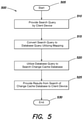
- FIG. 5 is a flow diagram for searching a change cache database in accordance with an example embodiment.
- the procedure 500 starts at step 505 and continues to step 510 where a client provides a search query to search the change cache database.
- the client may input the search query into a GUI or CLI.
- a user operating the client may utilize a pointing device and/or keyboard to input the search query into the GUI or CLI.
- the search query may be, for example, an ECSQLTM query of classes and properties.
- step 515 the query is converted to a database query utilizing a mapping between classes and properties of the search query and the rows and columns of the change cache database.
- the mapping may be maintained with the locally stored briefcase 152 and the client 150 may utilize the mapping to translate/convert the receive search query of classes and properties to rows and columns of the change cache database.
- the procedure continues to step 520 and the database query is utilized to search the change cache database.
- the database query includes one or more particular columns and/or rows identified in the mapping, and the data from the one or more particular column and/or rows is obtained.
- the procedure continues to step 525 and the results from the search of the change cache database are provided to the client. Specifically, the results may be displayed on a display screen of the client. For example, the results may be displayed in the GUI or CLI.
- the procedure then ends at step 530 .
- the change cache database 300 is an improved database in its structure (organization) and operability.
- the change cache database of the present invention change cache database provides users with the ability to implement more robust and efficient searches to inspect the changes that are made to the repository.
- the results from a search of the change cache database may allow a user to understand the changes made to the repository.
- a particular user may learn of the changes made to the repository by other users over a particular time span.
- the change cache database provides the user with the ability to perform a structured analysis on a subset of the changes made to the repository, or on changes made to a particular element. For example, a client device may search the change cache database to analyze just the changes made to a particular infrastructure element.
- the information from the change cache database may be utilized to determine which infrastructure elements are being actively changed such that a heat map of regions of an infrastructure model can be generated.
- the change cache database may be utilized to generate reports associated with the changes made to a repository such that the maturity of the repository from its genesis can be understood more effectively.
- the changesets created at client 150 may be discarded after they are transmitted to the cloud-based software 120 .
- the memory requirements of the client devices are reduced.
- the change cache database and its structure allows for more efficient searches that require less processing capabilities of the client devices.
- software implementations may include electronic device-executable instructions (e.g., computer-executable instructions) stored in a non-transitory electronic device-readable medium (e.g., a non-transitory computer-readable medium), such as a volatile memory, a persistent storage device, or other tangible medium.
- Hardware implementations may include logic circuits, application specific integrated circuits, and/or other types of hardware components.
- combined software/hardware implementations may include both electronic device-executable instructions stored in a non-transitory electronic device-readable medium, as well as one or more hardware components.
Landscapes
- Engineering & Computer Science (AREA)
- Theoretical Computer Science (AREA)
- Data Mining & Analysis (AREA)
- Databases & Information Systems (AREA)
- Physics & Mathematics (AREA)
- General Engineering & Computer Science (AREA)
- General Physics & Mathematics (AREA)
- Computational Linguistics (AREA)
- Computer Security & Cryptography (AREA)
- Information Retrieval, Db Structures And Fs Structures Therefor (AREA)
Abstract
Description
-
- SELECT ChangedInstance.Id, OpCode FROM ecchange.change.InstanceChange WHERE Summary.Id=X
where “X” is a change summary identifier.
- SELECT ChangedInstance.Id, OpCode FROM ecchange.change.InstanceChange WHERE Summary.Id=X
-
- SELECT i.ChangedInstance.Id, p.AccessString, i.OpCode FROM change.PropertyValueChange p
- JOIN change.InstanceChange i USING change.InstanceChangeOwnsPropertyValueChanges
- WHERE i.Summary.Id=X
Where “X” is the particular identifier of the change summary.
- SELECT i.ChangedInstance.Id, p.AccessString, i.OpCode FROM change.PropertyValueChange p
-
- SELECT Summary.Id,Author,Description,PushDate FROM ecchange.imodelchange.ChangeSet WHERE WsgId=X
where “X” is the changeset identifier.
- SELECT Summary.Id,Author,Description,PushDate FROM ecchange.imodelchange.ChangeSet WHERE WsgId=X
-
- SELECT Id, Code, Rating, Type FROM plant.Valve.Changes(:changeSummaryId, ‘AfterInsert’) WHERE Type=‘ButterflyValve’
-
- SELECT Id, Code, Rating, Type FROM plant.Valve.Changes(:changeSummaryId, ‘BeforeUpdate’) WHERE Type=‘GateValve’
-
- SELECT DISTINCT Summary.Id FROM change.InstanceChange WHERE ChangedInstance.Id=X
where “X” is the changed instance identifier.
- SELECT DISTINCT Summary.Id FROM change.InstanceChange WHERE ChangedInstance.Id=X
-
- SELECT DISTINCT ic.Summary.Id
- FROM change.InstanceChange is
- JOIN meta.ECClassDef c
- ON ic.ChangedInstance.ClassId=c.ECInstanceId
- WHERE c.Name=‘ButterflyValve’ AND ic.OpCode=OpCode.Insert
- SELECT DISTINCT ic.Summary.Id
Claims (14)
Priority Applications (1)
| Application Number | Priority Date | Filing Date | Title |
|---|---|---|---|
| US16/156,824 US11226953B2 (en) | 2018-10-10 | 2018-10-10 | Technique for generating a change cache database utilized to inspect changes made to a repository |
Applications Claiming Priority (1)
| Application Number | Priority Date | Filing Date | Title |
|---|---|---|---|
| US16/156,824 US11226953B2 (en) | 2018-10-10 | 2018-10-10 | Technique for generating a change cache database utilized to inspect changes made to a repository |
Publications (2)
| Publication Number | Publication Date |
|---|---|
| US20200117729A1 US20200117729A1 (en) | 2020-04-16 |
| US11226953B2 true US11226953B2 (en) | 2022-01-18 |
Family
ID=70161301
Family Applications (1)
| Application Number | Title | Priority Date | Filing Date |
|---|---|---|---|
| US16/156,824 Active 2039-03-15 US11226953B2 (en) | 2018-10-10 | 2018-10-10 | Technique for generating a change cache database utilized to inspect changes made to a repository |
Country Status (1)
| Country | Link |
|---|---|
| US (1) | US11226953B2 (en) |
Cited By (2)
| Publication number | Priority date | Publication date | Assignee | Title |
|---|---|---|---|---|
| US20220043797A1 (en) * | 2020-08-05 | 2022-02-10 | Salesforce.Com, Inc. | Virtual dataset management database system |
| US11455437B1 (en) * | 2019-10-15 | 2022-09-27 | Bentley Systems, Incorporated | Techniques for generating and retrieving change summary data and aggregated model version data for an infrastructure model |
Families Citing this family (5)
| Publication number | Priority date | Publication date | Assignee | Title |
|---|---|---|---|---|
| US11316841B2 (en) * | 2019-03-25 | 2022-04-26 | Micron Technology, Inc. | Secure communication between an intermediary device and a network |
| CN112732751B (en) * | 2020-12-30 | 2023-04-28 | 北京懿医云科技有限公司 | Medical data processing method, device, storage medium and equipment |
| US11163798B1 (en) | 2021-03-21 | 2021-11-02 | Snowflake Inc. | Database replication to remote deployment with automated fulfillment |
| CN113360513A (en) * | 2021-06-24 | 2021-09-07 | 平安普惠企业管理有限公司 | Report influence analysis method and device, computer equipment and storage medium |
| US20240220505A1 (en) * | 2022-12-29 | 2024-07-04 | Palantir Technologies Inc. | Systems and methods for context-aware change management |
Citations (18)
| Publication number | Priority date | Publication date | Assignee | Title |
|---|---|---|---|---|
| US5758150A (en) * | 1995-10-06 | 1998-05-26 | Tele-Communications, Inc. | System and method for database synchronization |
| US6526418B1 (en) * | 1999-12-16 | 2003-02-25 | Livevault Corporation | Systems and methods for backing up data files |
| US20050262048A1 (en) * | 2004-05-05 | 2005-11-24 | International Business Machines Corporation | Dynamic database access via standard query language and abstraction technology |
| US20060253419A1 (en) * | 2002-07-20 | 2006-11-09 | Microsoft Corporation | Translation of object queries involving inheritence |
| US20080052719A1 (en) * | 2006-08-23 | 2008-02-28 | Peter John Briscoe | Resource management system |
| US7395258B2 (en) | 2004-07-30 | 2008-07-01 | International Business Machines Corporation | System and method for adaptive database caching |
| US20090144696A1 (en) * | 2007-11-29 | 2009-06-04 | Max Rydahl Andersen | Code completion for object relational mapping query language (oql) queries |
| US7657406B2 (en) | 2005-06-09 | 2010-02-02 | Intepoint, Llc | Multi-infrastructure modeling system |
| US20100211662A1 (en) * | 2009-02-13 | 2010-08-19 | Graham Glendinning | Method and system for specifying planned changes to a communications network |
| US20110314138A1 (en) * | 2010-06-21 | 2011-12-22 | Hitachi, Ltd. | Method and apparatus for cause analysis configuration change |
| US20130117232A1 (en) | 2011-11-09 | 2013-05-09 | Microsoft Corporation | Snapshots of database models |
| US20140172791A1 (en) * | 2011-10-18 | 2014-06-19 | Microsoft Corporation | Application of a differential dataset to a data store using sequential change sets |
| US20150007176A1 (en) * | 2013-06-26 | 2015-01-01 | Fujitsu Limited | Analysis support method, analysis supporting device, and recording medium |
| US9998551B1 (en) * | 2016-10-24 | 2018-06-12 | Palantir Technologies Inc. | Automatic discovery and registration of service application for files introduced to a user interface |
| US10268709B1 (en) * | 2013-03-08 | 2019-04-23 | Datical, Inc. | System, method and computer program product for database change management |
| US20190294722A1 (en) | 2018-03-20 | 2019-09-26 | Locus Robotics Corp. | Change management system for data synchronization within an enterprise portal application |
| US10558529B2 (en) | 2016-11-11 | 2020-02-11 | Sap Se | Database object delivery infrastructure |
| US20200117445A1 (en) | 2018-10-12 | 2020-04-16 | Bentley Systems, Incorporated | Changeset conflict rebasing |
-
2018
- 2018-10-10 US US16/156,824 patent/US11226953B2/en active Active
Patent Citations (18)
| Publication number | Priority date | Publication date | Assignee | Title |
|---|---|---|---|---|
| US5758150A (en) * | 1995-10-06 | 1998-05-26 | Tele-Communications, Inc. | System and method for database synchronization |
| US6526418B1 (en) * | 1999-12-16 | 2003-02-25 | Livevault Corporation | Systems and methods for backing up data files |
| US20060253419A1 (en) * | 2002-07-20 | 2006-11-09 | Microsoft Corporation | Translation of object queries involving inheritence |
| US20050262048A1 (en) * | 2004-05-05 | 2005-11-24 | International Business Machines Corporation | Dynamic database access via standard query language and abstraction technology |
| US7395258B2 (en) | 2004-07-30 | 2008-07-01 | International Business Machines Corporation | System and method for adaptive database caching |
| US7657406B2 (en) | 2005-06-09 | 2010-02-02 | Intepoint, Llc | Multi-infrastructure modeling system |
| US20080052719A1 (en) * | 2006-08-23 | 2008-02-28 | Peter John Briscoe | Resource management system |
| US20090144696A1 (en) * | 2007-11-29 | 2009-06-04 | Max Rydahl Andersen | Code completion for object relational mapping query language (oql) queries |
| US20100211662A1 (en) * | 2009-02-13 | 2010-08-19 | Graham Glendinning | Method and system for specifying planned changes to a communications network |
| US20110314138A1 (en) * | 2010-06-21 | 2011-12-22 | Hitachi, Ltd. | Method and apparatus for cause analysis configuration change |
| US20140172791A1 (en) * | 2011-10-18 | 2014-06-19 | Microsoft Corporation | Application of a differential dataset to a data store using sequential change sets |
| US20130117232A1 (en) | 2011-11-09 | 2013-05-09 | Microsoft Corporation | Snapshots of database models |
| US10268709B1 (en) * | 2013-03-08 | 2019-04-23 | Datical, Inc. | System, method and computer program product for database change management |
| US20150007176A1 (en) * | 2013-06-26 | 2015-01-01 | Fujitsu Limited | Analysis support method, analysis supporting device, and recording medium |
| US9998551B1 (en) * | 2016-10-24 | 2018-06-12 | Palantir Technologies Inc. | Automatic discovery and registration of service application for files introduced to a user interface |
| US10558529B2 (en) | 2016-11-11 | 2020-02-11 | Sap Se | Database object delivery infrastructure |
| US20190294722A1 (en) | 2018-03-20 | 2019-09-26 | Locus Robotics Corp. | Change management system for data synchronization within an enterprise portal application |
| US20200117445A1 (en) | 2018-10-12 | 2020-04-16 | Bentley Systems, Incorporated | Changeset conflict rebasing |
Cited By (2)
| Publication number | Priority date | Publication date | Assignee | Title |
|---|---|---|---|---|
| US11455437B1 (en) * | 2019-10-15 | 2022-09-27 | Bentley Systems, Incorporated | Techniques for generating and retrieving change summary data and aggregated model version data for an infrastructure model |
| US20220043797A1 (en) * | 2020-08-05 | 2022-02-10 | Salesforce.Com, Inc. | Virtual dataset management database system |
Also Published As
| Publication number | Publication date |
|---|---|
| US20200117729A1 (en) | 2020-04-16 |
Similar Documents
| Publication | Publication Date | Title |
|---|---|---|
| US11226953B2 (en) | Technique for generating a change cache database utilized to inspect changes made to a repository | |
| US12424303B2 (en) | Clinical data management system | |
| AU2021202623B2 (en) | System for synchronization of changes in edited websites and interactive applications | |
| US12566783B2 (en) | Method and apparatus for implementing a set of integrated data systems | |
| EP3695290B1 (en) | Alignment of source infrastructure data with a bis conceptual schema | |
| US10783124B2 (en) | Data migration in a networked computer environment | |
| Karnitis et al. | Migration of relational database to document-oriented database: structure denormalization and data transformation | |
| US10095717B2 (en) | Data archive vault in big data platform | |
| EP3864504B1 (en) | Changeset conflict rebasing | |
| US8543539B2 (en) | Method and system for capturing change of data | |
| US20190079958A1 (en) | Intelligent model hierarchy for infrastructure modeling | |
| US11210181B2 (en) | System and method for implementing data manipulation language (DML) on Hadoop | |
| US20170286100A1 (en) | User-configurable database artifacts | |
| CN111753141B (en) | A data management method and related equipment | |
| CN105426128A (en) | Index maintenance method and device | |
| Kobayashi et al. | Decoupling identity resolution from the maintenance of identity information | |
| US11455437B1 (en) | Techniques for generating and retrieving change summary data and aggregated model version data for an infrastructure model | |
| CN114356945A (en) | Data processing method, data processing device, computer equipment and storage medium | |
| de Bhróithe et al. | A generic approach to schema evolution in live relational databases | |
| JP5673246B2 (en) | Data store control device, data store control program, and data store control method | |
| Hsieh et al. | A method for web application data migration based on RESTful API: A case study of ezScrum | |
| Makoondlall et al. | ZDLC: Layered lineage report across technologies | |
| CN120653645A (en) | Data storage method, device, equipment and medium | |
| Varghese | Persistence with MongoDB | |
| Kaltenthaler et al. | Synchronized data management and its integration into a graphical user interface for archaeological related disciplines |
Legal Events
| Date | Code | Title | Description |
|---|---|---|---|
| FEPP | Fee payment procedure |
Free format text: ENTITY STATUS SET TO UNDISCOUNTED (ORIGINAL EVENT CODE: BIG.); ENTITY STATUS OF PATENT OWNER: LARGE ENTITY |
|
| AS | Assignment |
Owner name: BENTLEY SYSTEMS, INCORPORATED, PENNSYLVANIA Free format text: ASSIGNMENT OF ASSIGNORS INTEREST;ASSIGNORS:RAMAN, RAMANUJAM;KHAN, AFFAN;EBERLE, KRISCHAN;AND OTHERS;SIGNING DATES FROM 20191217 TO 20200310;REEL/FRAME:052065/0280 |
|
| STPP | Information on status: patent application and granting procedure in general |
Free format text: NON FINAL ACTION MAILED |
|
| STPP | Information on status: patent application and granting procedure in general |
Free format text: RESPONSE TO NON-FINAL OFFICE ACTION ENTERED AND FORWARDED TO EXAMINER |
|
| STPP | Information on status: patent application and granting procedure in general |
Free format text: FINAL REJECTION MAILED |
|
| STPP | Information on status: patent application and granting procedure in general |
Free format text: FINAL REJECTION MAILED |
|
| STPP | Information on status: patent application and granting procedure in general |
Free format text: DOCKETED NEW CASE - READY FOR EXAMINATION |
|
| STPP | Information on status: patent application and granting procedure in general |
Free format text: NON FINAL ACTION MAILED |
|
| STPP | Information on status: patent application and granting procedure in general |
Free format text: RESPONSE TO NON-FINAL OFFICE ACTION ENTERED AND FORWARDED TO EXAMINER |
|
| STPP | Information on status: patent application and granting procedure in general |
Free format text: NOTICE OF ALLOWANCE MAILED -- APPLICATION RECEIVED IN OFFICE OF PUBLICATIONS |
|
| STPP | Information on status: patent application and granting procedure in general |
Free format text: PUBLICATIONS -- ISSUE FEE PAYMENT VERIFIED |
|
| STCF | Information on status: patent grant |
Free format text: PATENTED CASE |
|
| AS | Assignment |
Owner name: PNC BANK, NATIONAL ASSOCIATION, PENNSYLVANIA Free format text: SECURITY INTEREST;ASSIGNOR:BENTLEY SYSTEMS, INCORPORATED;REEL/FRAME:069268/0042 Effective date: 20241018 |
|
| MAFP | Maintenance fee payment |
Free format text: PAYMENT OF MAINTENANCE FEE, 4TH YEAR, LARGE ENTITY (ORIGINAL EVENT CODE: M1551); ENTITY STATUS OF PATENT OWNER: LARGE ENTITY Year of fee payment: 4 |