US112265A - Improvement in feed-cutters - Google Patents
Improvement in feed-cutters Download PDFInfo
- Publication number
- US112265A US112265A US112265DA US112265A US 112265 A US112265 A US 112265A US 112265D A US112265D A US 112265DA US 112265 A US112265 A US 112265A
- Authority
- US
- United States
- Prior art keywords
- wheel
- secured
- feed
- dogs
- rollers
- Prior art date
- Legal status (The legal status is an assumption and is not a legal conclusion. Google has not performed a legal analysis and makes no representation as to the accuracy of the status listed.)
- Expired - Lifetime
Links
- 241000282472 Canis lupus familiaris Species 0.000 description 13
- 239000010902 straw Substances 0.000 description 9
- 230000013707 sensory perception of sound Effects 0.000 description 3
- CVRALZAYCYJELZ-UHFFFAOYSA-N O-(4-bromo-2,5-dichlorophenyl) O-methyl phenylphosphonothioate Chemical compound C=1C=CC=CC=1P(=S)(OC)OC1=CC(Cl)=C(Br)C=C1Cl CVRALZAYCYJELZ-UHFFFAOYSA-N 0.000 description 1
- 238000010276 construction Methods 0.000 description 1
- 239000000428 dust Substances 0.000 description 1
- 210000005069 ears Anatomy 0.000 description 1
- 239000000463 material Substances 0.000 description 1
- 230000001105 regulatory effect Effects 0.000 description 1
- 230000000717 retained effect Effects 0.000 description 1
Images

Classifications
-
- B—PERFORMING OPERATIONS; TRANSPORTING
- B02—CRUSHING, PULVERISING, OR DISINTEGRATING; PREPARATORY TREATMENT OF GRAIN FOR MILLING
- B02C—CRUSHING, PULVERISING, OR DISINTEGRATING IN GENERAL; MILLING GRAIN
- B02C18/00—Disintegrating by knives or other cutting or tearing members which chop material into fragments
- B02C18/06—Disintegrating by knives or other cutting or tearing members which chop material into fragments with rotating knives
- B02C18/14—Disintegrating by knives or other cutting or tearing members which chop material into fragments with rotating knives within horizontal containers
- B02C18/148—Disintegrating by knives or other cutting or tearing members which chop material into fragments with rotating knives within horizontal containers specially adapted for disintegrating plastics, e.g. cinematographic films
-
- A—HUMAN NECESSITIES
- A01—AGRICULTURE; FORESTRY; ANIMAL HUSBANDRY; HUNTING; TRAPPING; FISHING
- A01F—PROCESSING OF HARVESTED PRODUCE; HAY OR STRAW PRESSES; DEVICES FOR STORING AGRICULTURAL OR HORTICULTURAL PRODUCE
- A01F29/00—Cutting apparatus specially adapted for cutting hay, straw or the like
- A01F29/09—Details
- A01F29/095—Mounting or adjusting of knives
-
- Y—GENERAL TAGGING OF NEW TECHNOLOGICAL DEVELOPMENTS; GENERAL TAGGING OF CROSS-SECTIONAL TECHNOLOGIES SPANNING OVER SEVERAL SECTIONS OF THE IPC; TECHNICAL SUBJECTS COVERED BY FORMER USPC CROSS-REFERENCE ART COLLECTIONS [XRACs] AND DIGESTS
- Y10—TECHNICAL SUBJECTS COVERED BY FORMER USPC
- Y10T—TECHNICAL SUBJECTS COVERED BY FORMER US CLASSIFICATION
- Y10T83/00—Cutting
- Y10T83/485—Cutter with timed stroke relative to moving work
- Y10T83/492—With means to vary timing of tool feed
Definitions
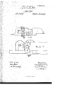
- Figure 2 is a side view, withthe fly-wheel attached.
- B ign-re A3 isa sid'eyiew, withthe fly-wheel removed.
- Figure-4 is a longitudinal ⁇ - ⁇ sectional view ⁇ through theceuter of the machine;
- This invention belongsto that class of straw and fodder-cuttersih which' arevolving knifeor blade, Y working overa stntionarylbar, is used, and consistsiu a novel arrangement of Qmechanism, ⁇ whereby the straw or fodder is not only uniformly fed for the-action of h "the k
- the lower roller revolves in stationary bearings
- Our iuven 'ou alsoconsistsinthe combination and arrangement ofthe mechanism by which a simultan# cous ⁇ and uniform or like movement Ais imparted to the feed-rollers and this we accomplish by means of ratchetwheelsseenred on their, Vaxles or shafts, and springpawls or dogs, the latter being connected by pitmanrods with theshortarin of ⁇ a T-shaped lever,'the ⁇ loog armof which has its ⁇ hearings and slides in guide-boxes secured to thel sideofthe cuttingbox or frame;
- This connectingbar or rod that unites the ily-wheel i ⁇ and the T-shaped lever is permanently secured to the latter atrpr oua pivotfceuterg and to the wheel hy meansrofa slottedfplate ⁇ or coupling-link and a set; y screw. di d y h A l ⁇ This arrangementaffords a complete system ofadjustment forthe feed mechanism, and one by which it can heregulatedatpleasure.
- A is the frame: i
- B B' are the feed-rollers, and their entire surface is finely ute'd.
- rollers, B B' are each provided with an axleshaft, b, and are supported in cast-metallic bearingplates, C C, secured to the frame A on its opposite sides,a11d at the discharge end ofthe feed box.
- the shaft b of the lower roller B is secured in ⁇ fixed bearings, while the shaft b of the roller B is secured in a metallic cap, D, and rests in anopen slot in the plates G C. t
- a guidecasing for the roller not only partially protecting the same from dust, as an ordinary rectangular plate would do, but serving as a guide, not only readily enabling the roller to accommodate itself to any thickness or 'unevenness of material fed, but, at the same time, inclosing it, as it does, always retaining theroller on the true line of' its work.
- this cap is also secured the retaining-paw] H,of the ratchet-wheel, which is securel to the shift of the feed-roller B', and which is consequently movedexacfly as is the roller, always being ⁇ in position to act effectively on its ratchet 'lhecenter or arch of' the how of this spring D rests against a horizontal armor bar, D", secured onv the frame.
- This blade is so arranged as to work in connection Awith the stationary bar or knife Gl, which is also secured in thebearing-plates O C.
- X's a hinged metallic cap that in'closes the knives, and is' simply to guard against or prevent accident.
- the main or driving-wheel Fz works on an independentv hearing fastened to the frame A.
- GG are two ratchet-wheels, and are permanently .secured on the shafts b b ofthe feed-rollers B B'.
- hh are two pendentllips, and are bolted onto the pawls or dogs H H.
- T hese hold the ratchet-wheels, and prevent any backward movement of the rollers after they have been carried forward through the action of the pa'wls or dogs H H.
- J is a T-sha-pedmotor-lever, the long arm j of' which is lsupported .and so secured iu a guide-box, J', attached to the frame A, as to allow of its freely sliding backward and forward in a horizontal direction.
- pitman-rods K K connect the T-shaped lever with the pawls or dogs H H, and are the medium through which the motion of the one is communicated to the other.
- This T-shaped level' is connected to the fly-wheel by means of abar or plate, L.
- This bar or plate. is att-ached to the lever on a pivot center, Land which is immediately at the point of union between its long and short arm.
- This plate or link enters groove orrecess on the face of the. ily-wheel F, and is secured or fastened at any desired point along its entire surface by means of a screw, m.
- rollers B B', plates C C, cap D, having a retaining pawl or dog, H', attached, rods d d, and spring D1, when'the same are combined and arranged substantially as described.
Landscapes
- Engineering & Computer Science (AREA)
- Food Science & Technology (AREA)
- Life Sciences & Earth Sciences (AREA)
- Environmental Sciences (AREA)
- Threshing Machine Elements (AREA)
Description
JAMESBQMQQLINTONAun WILLIAM MCcLiN'roN. or oALioN, onto. y
;` Leners Parent No.` 112265,. @and February 2s, 1871.
IMPROVEMENT iN FEED-correas.
`The` Schedulereferred to in these Letters Patent and making part of the same.-
` `To all whom 'it maycoacernf `Be it known that weJhMEs B. McCmn'rox and `WILLIAM MCOLlnTON, of Galion, in the count-y of Grawi'ordand State of Ohio, have invented `certain new and useful Improvements in Straw andlodder- Cutters and we do hereby declare that the following `is a full, clear, and exact description of the same, `reference being had to" the. accnnpanyiug drawing i andlto the letters ofreference` murkedthereon making partei' this speciiication,y iuwhicli- Figure 1 is a4 topplan view. 1
Figure 2 is a side view, withthe fly-wheel attached. B ign-re A3 isa sid'eyiew, withthe fly-wheel removed. Figure-4 is a longitudinal`- `sectional view` through theceuter of the machine;
This invention belongsto that class of straw and fodder-cuttersih which' arevolving knifeor blade, Y working overa stntionarylbar, is used, and consistsiu a novel arrangement of Qmechanism,` whereby the straw or fodder is not only uniformly fed for the-action of h "the k|`1ives,but in vhieh the feed mechanism is capa- ,ble of such adjustment asiusures the cutting of the straw or fodder ofa greater or lesser length, as occasion may require. i r
The lower roller revolves in stationary bearings,
i while the upper hasits hearings inra guide-slot, being retained in position hylmeans` of a metallic cap, rods, and spring, so `arrzingednthat while a slight 'vertical play, is allowed its axle, thetensionof the spring shall l f f lie/constantly exerted in drawing it to and retaining it in such a positionasto cause it torso bite or press the substauce'to be cot astto insure it being properly i to the knives.
Our iuven 'ou alsoconsistsinthe combination and arrangement ofthe mechanism by which a simultan# cous `and uniform or like movement Ais imparted to the feed-rollers and this we accomplish by means of ratchetwheelsseenred on their, Vaxles or shafts, and springpawls or dogs, the latter being connected by pitmanrods with theshortarin of `a T-shaped lever,'the`loog armof which has its `hearings and slides in guide-boxes secured to thel sideofthe cuttingbox or frame;
rThis'l'7-shaped lever is so connected with the fly- Awheel hy'a-rod or bareplatethat the revolution of the i ,wheel shall cause the' lever `to nrove or slide to and V `fro in a horizontal line or in a.- horizontal direction.
This connectingbar or rod that unites the ily-wheel i `and the T-shaped lever is permanently secured to the latter atrpr oua pivotfceuterg and to the wheel hy meansrofa slottedfplate `or coupling-link and a set; y screw. di d y h A l `This arrangementaffords a complete system ofadjustment forthe feed mechanism, and one by which it can heregulatedatpleasure.
As the movement of the rollers depends entirely on this connecting-rod, of course the speed or rate at which they feed is controlled entirely by its point of bearing on the y \vheel.v Therefore, to vary the cut oi' the machine, or to cause it to cut the straw or fodder of a greater or lesser length, you simply have to change the point at which the connecting-roll has its d bearing on the fly-Wheel, and which is done h v moving the slotted bar or coupling-link so as to carry the end' oi the connecting-bar further from or bri nging it nearer to the axle ofthe wheel, as thecase may be, or the length of cut desired may require.
When the ratchet-wheels are moved forward by the spring-pawls or dogs they are held in their place and prevented from returning by retaining-pawls or dogs, while the spriug-pawls or dogs are themselves prevented from slippiu g or being thrown ont of direct contact with the ratchet periphery of the wheels by means ofthe plates on which they have their hearings and pendent-lips secured .to the pawl.
To enable others skilled in the art to make and use ourinveution, we will now proceed to describe its construction and'operation.
A is the frame: i
A, the cutting-box; and
A2, the spout or chute for the cut-straw to run down, all of which are constructed in the usual manner.
B B' are the feed-rollers, and their entire surface is finely ute'd.
'These rollers, B B', are each provided with an axleshaft, b, and are supported in cast-metallic bearingplates, C C, secured to the frame A on its opposite sides,a11d at the discharge end ofthe feed box.
The shaft b of the lower roller B is secured in `fixed bearings, while the shaft b of the roller B is secured in a metallic cap, D, and rests in anopen slot in the plates G C. t
(l d are two. vertical rods, supported in ears on the cap D, which are arranged at such point ou the side flanged-plate thereof that when gthe roller B is in- 1 serted Vits shaft rests ou the right-angled head of the rods.
` These rods d ll have screw-threads cut on the lower for receiviugvand securing the shaft b-ot' the roller B',
and is so arranged, as it were, to act a; a guidecasing for the roller, not only partially protecting the same from dust, as an ordinary rectangular plate would do, but serving as a guide, not only readily enabling the roller to accommodate itself to any thickness or 'unevenness of material fed, but, at the same time, inclosing it, as it does, always retaining theroller on the true line of' its work.
'lo this cap is also secured the retaining-paw] H,of the ratchet-wheel, which is securel to the shift of the feed-roller B', and which is consequently movedexacfly as is the roller, always being`in position to act effectively on its ratchet 'lhecenter or arch of' the how of this spring D rests against a horizontal armor bar, D", secured onv the frame.
Byt-his armngement the tension or power of the spring is constantly exerted in drawing the roller in suchcontact with thc roller B as to insure that they shall so press or bite the straw or fodder as to secure a proper feeding ofthe Sallie to the knives.
On the plates C C, and in front ofthe rollers B B', in suitable'bearings, rests and works the shaft E.
To this shaft E are keyed, by clamping jaws, the arms e c,-to which the knife or blade E is attached.
This blade is so arranged as to work in connection Awith the stationary bar or knife Gl, which is also secured in thebearing-plates O C.
X's a hinged metallic cap that in'closes the knives, and is' simply to guard against or prevent accident.
f 0n the opposite ends ofthe shaft E are secured the ily-wheel li and the pinionwheel 1*".
'.lhis pinion-wheel Fl meshes with the main or drivingratchet crank-wheel F2, from which the power is receivedthatoperates not only the knife but the en'- tire feed mechanism.
The main or driving-wheel Fz works on an independentv hearing fastened to the frame A.
GG are two ratchet-wheels, and are permanently .secured on the shafts b b ofthe feed-rollers B B'.
' il G' are two bearingplates, and are also secured on the Shafts. f i
* These plates G'G are secured innnediately in front 0f the inner lfaceof` the ratchet-wheels, and are attached in such manner as to allow of their free movement.
To these plates are'secured the spring-p-.twls or dogs 11H, which work theratchet-wheels G G, anal through them the feed-rollers B B'.
hh are two pendentllips, and are bolted onto the pawls or dogs H H.
These project down on t-hc outside of the. wheels G G, and, in connection with the plates G' G', which extend up en the inner surface of' the wheels, prevent the pawls or dogs f'rom slipping off the wheels G G or `falling nt'of direct Contact with the ratchet peripheries thereof'.
H' H'are two dogs or rctaininggpawls, one secured 'to the cap D, as before stated, and the other to the frame A.-
T hese hold the ratchet-wheels, and prevent any backward movement of the rollers after they have been carried forward through the action of the pa'wls or dogs H H.
J is a T-sha-pedmotor-lever, the long arm j of' which is lsupported .and so secured iu a guide-box, J', attached to the frame A, as to allow of its freely sliding backward and forward in a horizontal direction.
In eyes, k k, at theends of the short, or, when secured in the guide-box, the vertical arm of this lever, are attached pitman-rods, K K.
These pitman-rods K K connect the T-shaped lever with the pawls or dogs H H, and are the medium through which the motion of the one is communicated to the other.
This T-shaped level' is connected to the fly-wheel by means of abar or plate, L.
This bar or plate. is att-ached to the lever on a pivot center, Land which is immediately at the point of union between its long and short arm.
The other end of' this bail is secured to a wrist-pn,v
1', on a slotted plate or linlt M.
This plate or link enters groove orrecess on the face of the. ily-wheel F, and is secured or fastened at any desired point along its entire surface by means of a screw, m.
The operation is as follows: 'y
Power'being applied to the crank-wheel F2, in cousequence of its meshing with the pinion-wheel F1, that wheel is revolved, carrying,r with it the shaft E, thc knife EC'and iiy-wheel F. This revolution of the flywheel, through the connecting-bar or p|ate'L,'iu|parts a'horizontal orsliding movement to the T-shaped lever J, which, through the pitman-rods K 1K, work the pawls or dogs H H, and which, turning the ratchetwheels G G, revolve simultaneously the rollers B B', which,v biting the straw or fodder, feed it for the action of the knife. Now, the cut of the machine depending, as it does, entirely on the length ofthe stroke of' the bar or pla-te L, we can vary it'at pleasure simply by shifting the point at which the link M is secured in the groove on the fly-wheel F.I Therefore, when we desire to alter the cut, or cut the straw or fodder of eithera greater or lesser lengththan that at 'which the lnachine is set, we have simply to loosen the screw m and move the lilik M in the groove, so as to bring the end of the rod nearer to or remove it further from the axle E of the fly-wheel, as the case maybe. l v
We are aware that prior to our invention the connecting-bar has been attached to the fly-wheel by an adjustable bearing, whereby the length of its stroke could be regulated; therefore we do not' desire to be understood as broadly claiming this feature per se.
Having tlms fully described our invention,
What we claim tberin as new, and desire to secure by Letters Patent ofthe United States, is
l. The rollers B B', plates C C, cap D, having a retaining pawl or dog, H', attached, rods d d, and spring D1, when'the same are combined and arranged substantially as described.
y2. The T-shaped llever J, pitman-rods K K, dogs H H, ratchet-wheels G G, and connecting-bar L, secured to the fly-wheel as stated, when the same are so combined and arranged as to impart to the feed'- rollers an adjustable and uniform movement, substantially as described.
In testimony whereof we have signed our namesto this specification in the presence of two -subscribing witnesses.
' JAMES B. MC'GLINTON.
Witnesses WILLIAM MCGLINTON.
S. G. CUMMINGS, M. MCGLINTON.
Publications (1)
| Publication Number | Publication Date |
|---|---|
| US112265A true US112265A (en) | 1871-02-28 |
Family
ID=2181733
Family Applications (1)
| Application Number | Title | Priority Date | Filing Date |
|---|---|---|---|
| US112265D Expired - Lifetime US112265A (en) | Improvement in feed-cutters |
Country Status (1)
| Country | Link |
|---|---|
| US (1) | US112265A (en) |
-
0
- US US112265D patent/US112265A/en not_active Expired - Lifetime
Similar Documents
| Publication | Publication Date | Title |
|---|---|---|
| US112265A (en) | Improvement in feed-cutters | |
| US1195538A (en) | Darius t | |
| US181658A (en) | Improvement in straw-cutters | |
| US12610A (en) | Improvement in hulling cotton-seeds | |
| USRE2838E (en) | Franklin | |
| US390601A (en) | Feed-cutter | |
| US118235A (en) | Improvement in vegetable cutters | |
| US216486A (en) | Improvement in hay | |
| US165514A (en) | Improvement in straw-cutters | |
| US41637A (en) | Improvement in tobacco-cutters | |
| US449572A (en) | cameron | |
| US621704A (en) | Coupon cutting and dating machine | |
| US60069A (en) | schoolbt | |
| US73961A (en) | wainwright | |
| US49998A (en) | Improvement in sugar-cane mills | |
| US165043A (en) | Improvement in feed-cutters | |
| US86293A (en) | Improvement in mortising-machines | |
| US412040A (en) | Straw-cutter | |
| US119326A (en) | Improvement in straw-cutters | |
| US5169A (en) | Straw-cutter | |
| US167334A (en) | Improvement in straw-cutters | |
| US57121A (en) | Improvement in straw-cutters | |
| US95047A (en) | John h | |
| US166307A (en) | Improvement in straw-cutters | |
| US120781A (en) | Improvement in straw-cutters |