US11226494B2 - Wearable device and electrical connector with magnetic attraction - Google Patents
Wearable device and electrical connector with magnetic attraction Download PDFInfo
- Publication number
- US11226494B2 US11226494B2 US16/689,209 US201916689209A US11226494B2 US 11226494 B2 US11226494 B2 US 11226494B2 US 201916689209 A US201916689209 A US 201916689209A US 11226494 B2 US11226494 B2 US 11226494B2
- Authority
- US
- United States
- Prior art keywords
- magnetic attraction
- terminal structures
- attraction member
- wearable device
- pivotal
- Prior art date
- Legal status (The legal status is an assumption and is not a legal conclusion. Google has not performed a legal analysis and makes no representation as to the accuracy of the status listed.)
- Active, expires
Links
- 239000011521 glass Substances 0.000 claims description 15
- 230000005611 electricity Effects 0.000 claims description 6
- 238000013461 design Methods 0.000 description 11
- 238000000034 method Methods 0.000 description 4
- 238000012986 modification Methods 0.000 description 4
- 230000004048 modification Effects 0.000 description 4
- 230000008569 process Effects 0.000 description 4
- 230000003190 augmentative effect Effects 0.000 description 2
- 230000008901 benefit Effects 0.000 description 1
- 238000004891 communication Methods 0.000 description 1
- 238000011161 development Methods 0.000 description 1
- 230000006870 function Effects 0.000 description 1
- 230000007246 mechanism Effects 0.000 description 1
- 230000004044 response Effects 0.000 description 1
Images


Classifications
-
- G—PHYSICS
- G02—OPTICS
- G02C—SPECTACLES; SUNGLASSES OR GOGGLES INSOFAR AS THEY HAVE THE SAME FEATURES AS SPECTACLES; CONTACT LENSES
- G02C5/00—Constructions of non-optical parts
- G02C5/02—Bridges; Browbars; Intermediate bars
- G02C5/10—Intermediate bars or bars between bridge and side-members
-
- G—PHYSICS
- G02—OPTICS
- G02C—SPECTACLES; SUNGLASSES OR GOGGLES INSOFAR AS THEY HAVE THE SAME FEATURES AS SPECTACLES; CONTACT LENSES
- G02C5/00—Constructions of non-optical parts
- G02C5/22—Hinges
- G02C5/2209—Pivot bearings and hinge bolts other than screws
-
- G—PHYSICS
- G02—OPTICS
- G02B—OPTICAL ELEMENTS, SYSTEMS OR APPARATUS
- G02B27/00—Optical systems or apparatus not provided for by any of the groups G02B1/00 - G02B26/00, G02B30/00
- G02B27/01—Head-up displays
- G02B27/017—Head mounted
-
- G—PHYSICS
- G02—OPTICS
- G02C—SPECTACLES; SUNGLASSES OR GOGGLES INSOFAR AS THEY HAVE THE SAME FEATURES AS SPECTACLES; CONTACT LENSES
- G02C5/00—Constructions of non-optical parts
- G02C5/14—Side-members
- G02C5/146—Side-members having special front end
-
- G—PHYSICS
- G06—COMPUTING; CALCULATING OR COUNTING
- G06K—GRAPHICAL DATA READING; PRESENTATION OF DATA; RECORD CARRIERS; HANDLING RECORD CARRIERS
- G06K19/00—Record carriers for use with machines and with at least a part designed to carry digital markings
- G06K19/06—Record carriers for use with machines and with at least a part designed to carry digital markings characterised by the kind of the digital marking, e.g. shape, nature, code
- G06K19/067—Record carriers with conductive marks, printed circuits or semiconductor circuit elements, e.g. credit or identity cards also with resonating or responding marks without active components
- G06K19/07—Record carriers with conductive marks, printed circuits or semiconductor circuit elements, e.g. credit or identity cards also with resonating or responding marks without active components with integrated circuit chips
- G06K19/073—Special arrangements for circuits, e.g. for protecting identification code in memory
- G06K19/07309—Means for preventing undesired reading or writing from or onto record carriers
- G06K19/07345—Means for preventing undesired reading or writing from or onto record carriers by activating or deactivating at least a part of the circuit on the record carrier, e.g. ON/OFF switches
-
- G—PHYSICS
- G02—OPTICS
- G02B—OPTICAL ELEMENTS, SYSTEMS OR APPARATUS
- G02B27/00—Optical systems or apparatus not provided for by any of the groups G02B1/00 - G02B26/00, G02B30/00
- G02B27/01—Head-up displays
- G02B27/017—Head mounted
- G02B2027/0178—Eyeglass type
-
- G—PHYSICS
- G02—OPTICS
- G02C—SPECTACLES; SUNGLASSES OR GOGGLES INSOFAR AS THEY HAVE THE SAME FEATURES AS SPECTACLES; CONTACT LENSES
- G02C2200/00—Generic mechanical aspects applicable to one or more of the groups G02C1/00 - G02C5/00 and G02C9/00 - G02C13/00 and their subgroups
- G02C2200/02—Magnetic means
-
- G—PHYSICS
- G06—COMPUTING; CALCULATING OR COUNTING
- G06K—GRAPHICAL DATA READING; PRESENTATION OF DATA; RECORD CARRIERS; HANDLING RECORD CARRIERS
- G06K19/00—Record carriers for use with machines and with at least a part designed to carry digital markings
- G06K19/06—Record carriers for use with machines and with at least a part designed to carry digital markings characterised by the kind of the digital marking, e.g. shape, nature, code
- G06K19/067—Record carriers with conductive marks, printed circuits or semiconductor circuit elements, e.g. credit or identity cards also with resonating or responding marks without active components
- G06K19/07—Record carriers with conductive marks, printed circuits or semiconductor circuit elements, e.g. credit or identity cards also with resonating or responding marks without active components with integrated circuit chips
- G06K19/077—Constructional details, e.g. mounting of circuits in the carrier
- G06K19/07749—Constructional details, e.g. mounting of circuits in the carrier the record carrier being capable of non-contact communication, e.g. constructional details of the antenna of a non-contact smart card
- G06K19/07758—Constructional details, e.g. mounting of circuits in the carrier the record carrier being capable of non-contact communication, e.g. constructional details of the antenna of a non-contact smart card arrangements for adhering the record carrier to further objects or living beings, functioning as an identification tag
- G06K19/07762—Constructional details, e.g. mounting of circuits in the carrier the record carrier being capable of non-contact communication, e.g. constructional details of the antenna of a non-contact smart card arrangements for adhering the record carrier to further objects or living beings, functioning as an identification tag the adhering arrangement making the record carrier wearable, e.g. having the form of a ring, watch, glove or bracelet
Definitions
- the present disclosure relates to a wearable device and an electrical connector with magnetic attraction, and more particularly to a wearable device and an electrical connector with magnetic attraction that connects two components of the wearable device.
- a conventional wearable device e.g., a pair of virtual reality glasses, a pair of augmented reality glasses, a pair of mixed reality glasses, or a head-mounted display device/a helmet-mounted display device
- a battery When the user uses the conventional wearable device, the battery needs to be charged very often.
- a charging process of the conventional wearable device is almost implemented by connecting to an external wire, so that the user basically cannot use the conventional wearable device in the charging process. Accordingly, for related manufacturers, how users can quickly replace batteries has become one of the trends in the development of wearable devices.
- the present disclosure provides a wearable device and an electrical connector with magnetic attraction to effectively improve the issues associated with conventional wearable devices (e.g., a battery in conventional wearable device being difficult to be replaced).
- the present disclosure provides a wearable device, which includes a first body, at least one first magnetic attraction member, a plurality of first terminal structures, a first pivotal structure, a first electrical unit, a second body, at least one second magnetic attraction member, a plurality of second terminal structures, and a second electrical unit.
- the first body includes an engaging slot. Two inner walls of the engaging slot of the first body connected to each other are defined as two first functional walls.
- the at least one first magnetic attraction member is fixed on one of the two first functional walls.
- the first terminal structures are disposed in the other one of the two first functional walls and are spaced apart from each other.
- the first pivotal structure is arranged on the first body and is arranged adjacent to the engaging slot.
- the first electrical unit is connected to at least one of the first terminal structures.
- the second body has a second pivotal structure that is configured to be pivotally connected to the first pivotal structure.
- Two outer walls of the second body connected to each other are defined as two second functional walls.
- the at least one second magnetic attraction member is disposed on one of the two second functional walls.
- the second terminal structures are disposed in the other one of the two second functional walls and are spaced apart from each other.
- the second electrical unit is connected to at least one of the second terminal structures.
- the first magnetic attraction member and the second magnetic attraction member are fixed to each other by using a magnetic attraction there-between, so that the first body and the second body are fixed to each other, and the first terminal structures respectively contact the second terminal structures, and the first electrical unit connects with the second electrical unit.
- the present disclosure provides an electrical connector with magnetic attraction for being applied to a wearable device that includes a first body, at least one first magnetic attraction member and a plurality of first terminal structures which are respectively disposed on two inner walls of the first body connected to each other, a first pivotal structure disposed on the first body, and a first electrical unit connected to at least one of the first terminals structures.
- the electrical connector includes a second body, at least one second magnetic attraction member, and a plurality of second terminal structures.
- the second body has a second pivotal structure that is configured to be pivotally connected to the first pivotal structure.
- Two outer walls of the second body connected to each other are defined as two second functional walls.
- the at least one second magnetic attraction member is disposed on one of the two second functional walls.
- the at least one second magnetic attraction member is configured to fix to the at least one first magnetic attraction member by using a magnetic attraction there-between.
- the second terminal structures are disposed in the other one of the two second functional walls and are spaced apart from each other.
- the second terminal structures are configured to contact the first terminal structures.
- the second body can be conveniently detached from the first body by the cooperation of the first magnetic attraction member, the second magnetic attraction member, the first terminal structures, and the second terminal structures.
- the stability of connection between the first terminal structures and the second terminal structures can be maintained by the cooperation of the first magnetic attraction member and the second magnetic attraction member.
- FIG. 1 is a perspective view of a wearable device that is a pair of glasses according to the present disclosure.
- FIG. 2 and FIG. 3 are exploded views of FIG. 1 in different angles of view.
- FIG. 4 is an enlarged view of portion IV of FIG. 2 .
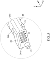
- FIG. 5 is an enlarged view of portion V of FIG. 3 .
- FIG. 6 is a perspective view showing an assembling process of wearable device of FIG. 1 .
- FIG. 7 is a perspective view of an electrical connector with magnetic attraction according to the present disclosure.
- FIG. 8 is a perspective view showing the electrical connector in another angle of view.
- FIG. 9 is a perspective view showing the electrical connector applied to a wearable device (e.g., a watch) according to the present disclosure.
- a wearable device e.g., a watch
- FIG. 10 and FIG. 11 are exploded views of FIG. 9 in different angles of view.
- FIG. 12 is an enlarged view of portion XII of FIG. 10 .
- FIG. 13 is an enlarged view of portion XIII of FIG. 11 .
- FIG. 14 is a perspective view showing an assembling process of the electrical connector of FIG. 9 .
- Numbering terms such as “first”, “second” or “third” can be used to describe various components, signals or the like, which are for distinguishing one component/signal from another one only, and are not intended to, nor should be construed to impose any substantive limitations on the components, signals or the like.
- an embodiment of the present disclosure provides a wearable device.
- the wearable device in the present embodiment is a pair of glasses, but the wearable device of the present disclosure is not limited thereto.
- the wearable device can be other types of wearable devices.
- the wearable device D 1 includes a first body 10 , two second bodies 20 , and a plurality of components fastened to (or formed on) the first body 10 and the two second bodies 20 .
- the first body 10 is a spectacle frame
- the two second bodies 20 are temples and are detachably connected to the first body 10 .
- the first body 10 and the two second bodies 20 are simply shown in the drawings, and can be changed according to design requirements.
- the wearable device D 1 of the present disclosure can be a pair of virtual reality glasses device, an augmented reality glasses device, a mixed reality glasses device, or a head-mounted display device, but is not limited thereto.
- the wearable device D 1 of the present embodiment is shown as the glasses having the two second bodies 20 , but the present disclosure is not limited thereto. In other embodiments of the present disclosure, the wearable device D 1 being a pair of glasses can include a single second body 20 and a conventional temple.
- first body 10 Two opposite end portions of the first body 10 each are provided with a first magnetic attraction member 11 , a plurality of first terminal structures 12 , a first pivotal structure 13 , and a first retaining structure 14 .
- the first body 10 is provided with a first electrical unit 15 embedded therein.
- each of the two opposite end portions of the first body 10 has an engaging slot 101 inwardly recessed therein along a first direction (e.g., a Y axis shown in FIG. 2 ).
- Two inner walls of the engaging slot 101 of the first body 10 connected to each other are defined as two first functional walls 101 A, 101 B.
- the first magnetic attraction member 11 is disposed on the first functional wall 101 A that forms a portion of engaging slot 101 , and can be a magnet or a component that can be attracted by a magnet.
- the size or shape of the engaging slot 101 is formed according to the shape of the second body 20 , and the drawings of the present embodiment only show one mode. In practical application, the number and shape of the first magnetic attraction member 11 can be changed according to design requirements, and are not limited to those shown in the drawings of the present embodiment.
- the first terminal structures 12 are disposed in the first functional wall 101 B that forms a portion of the engaging slot 101 , and are spaced apart from each other. In practical application, the number and shape of each of the first terminal structures 12 can be changed according to design requirements, and is not limited to the present embodiment. Each of the first terminal structures 12 is capable of transmitting signal, transmitting electricity, or being grounded according to design requirements.
- the first pivotal structure 13 can be a shaft hole that is recessed in the first functional wall 101 A along the first direction (e.g., the Y axis shown in FIG. 2 ).
- the shape and position of the first pivotal structure 13 is not limited to those shown in the drawings of the present embodiment.
- any configuration with the first pivotal structure 13 being arranged adjacent to the engaging slot 101 should be within the scope of the present disclosure.
- the first body 10 can be provided with a plurality of first electrical units 15 according to the functions of the wearable device D 1 , and the first electrical units 15 can be fixed onto a circuit board.
- the first electrical units 15 can include microprocessors, communication chips, and/or memory chips. At least one of the first electrical units 15 is connected to at least one of the first terminal structures 12 , and the first electrical unit 15 can receive signal or electricity transmitted from the first terminal structure 12 .
- each of the two second bodies 20 is a temple.
- One end of the second body 20 is configured to hang on user's ear, and the other end of the second body 20 has two outer walls connected to each other and defined as two second functional walls 20 A, 20 B.
- a second pivotal structure 21 extends from the second functional wall 20 A in a direction away from the second body 20 , and can be pivotally connected to the first pivotal structure 13 (shown in FIG. 4 ).
- the second pivotal structure 21 and the first pivotal structure 13 are pivotally connected to each other, the second body 20 is rotatable relative to the first body 10 along a rotation axis C.
- the first pivotal structure 13 is a shaft hole
- the second pivotal structure 21 is a column, but the present disclosure is not limited thereto.
- the second functional wall 20 A is further provided with a plurality of second terminal structures 22 spaced apart from each other.
- the second terminal structures 22 are configured to contact the first terminal structures 12 .
- the number of the second terminal structures 22 corresponds to that of the first terminal structures 12 .
- the second functional wall 20 B is provided with a second magnetic attraction member 23 that can be fixed to the first magnetic attraction member 11 by using a magnetic attraction there-between.
- the second magnetic attraction member 23 can be a magnet or a component that can be attracted by a magnet.
- the first body 10 and the second body 20 are fixed.
- the first body 10 and the second body 20 can be fixed through the magnetic attraction between the first magnetic attraction member 11 and the second magnetic attraction member 23 .
- the first magnetic attraction member 11 and the second magnetic attraction member 23 can be two magnets having different polarities, or can be a magnet and a component that can be attracted by the magnet.
- each of the magnetic attraction member 11 and the second magnetic attraction member 23 can be formed with other members (e.g., plastic cases) on an outer surface thereof according to design requirements.
- the number and shape of the second magnetic attraction member 23 can be changed according to design requirements, and are not limited to those shown in the drawings of the present embodiment.
- the second body 20 is provided with at least one second electrical unit 24 therein, and the at least one second electrical unit 24 is connected to at least one of the second terminal structures 22 .
- the second electrical unit 24 can be batteries, microprocessors, memory chips, sensors, earphones, controllers, or vibration motors, but is not limited thereto.
- the second electrical unit 24 arranged in one of the two second bodies 20 is a battery, and the second electrical unit 24 arranged in the other one of the two second bodies 20 can be a memory chip. Accordingly, the user can quickly replace the battery or the memory chip of the wearable device D 1 by replacing the original temple with a different temple (i.e., the different second bodies 20 ).
- the second electrical unit 24 in the second body 20 can be connected to (e.g., electrically connected to) the first electrical unit 15 in the first body 10 .
- the first electrical unit 15 in the first body 10 can be a microprocessor
- the second electrical unit 24 in the second body 20 can be a battery.
- the battery i.e., the first electrical unit 15
- the microprocessor i.e., the second electrical unit 24
- one of the two second bodies 20 can be assembled to one of the two opposite end portions of the first body 10 (i.e., the spectacle frame) by sequentially implementing the following steps.
- the second pivotal structure 21 of the second body 20 i.e., the temple
- the first pivotal structure 13 of the first body 10 i.e., the spectacle frame
- the second body 20 is rotated relative to the first body 10 through the cooperation of the first pivotal structure 13 and the second pivotal structure 21 , so that the second magnetic attraction member 23 can be rotated toward the first magnetic attraction member 11 (shown in FIG.
- the first magnetic attraction member 11 and the second magnetic attraction member 23 are fixed to each other, the first body 10 and the second body 20 are fixed to each other, the first terminal structures 12 contact the second terminal structures 22 , the second electrical unit 24 is connected to the first electrical unit 15 through the first terminal structures 12 and the second terminal structures 22 , so that the second electrical unit 24 can transmit electricity to the first electrical unit 15 , or can receive signals transmitted from the first electrical unit 15 .
- the first terminal structures 12 and the first magnetic attraction member 11 of the wearable device D 1 in the present disclosure are arranged on different axes (e.g., the first terminal structures 12 are arranged along the first direction, the Y axis shown in FIG. 2 , and the first magnetic attraction member 11 is arranged along a second direction, an X axis shown in FIG. 2 ), so that the connection between the first terminal structures 12 and the second terminal structures 22 is established only after the first magnetic attraction member 11 is fixed to the second magnetic attraction member 23 by using the magnetic attraction there-between, ensuring that the first terminal structures 12 and the second terminal structures 22 are in contact with each other at a right position. Moreover, since the first magnetic attraction 11 and the second magnetic attraction member 23 are provided, the first terminal structures 12 and the second terminal structures 22 can be in firm contact with each other.
- the wearable device D 1 of the present disclosure when the wearable device D 1 of the present disclosure is applied to the glasses of the present embodiment, the user can smoothly separate the temple (i.e., the second body 20 ) from the spectacle frame (i.e., the first body 10 ) by designing the first terminal structures 12 and the first magnetic attraction member 11 to be arranged on different axes, thereby effectively reducing the volume of connecting portions of the temple (i.e., the second body 20 ) and the spectacle.
- the temple i.e., the second body 20
- the temple when a user wears the glasses, the temple (i.e., the second body 20 ) is substantially perpendicular to the spectacle frame (i.e., the first body 10 ).
- the user can rotate the temple (i.e., the second body 20 ) toward one side away from the spectacle frame (i.e., the first body 10 ), and then move the temple (i.e., the second body 20 ) in a direction away from the spectacle frame (i.e., the first body 10 ), thereby conveniently and quickly detaching the temple (i.e., the second body 20 ) from the spectacle frame (i.e., the first body 10 ).
- the first body 10 can have a first retaining structure 14
- the second body 20 can have a second retaining structure 25 that can be engaged with the first retaining structure 14 , thereby helping to enhance the strength of connection between the first body 10 and the second body 20 .
- the first body 10 includes a side wall that is connected to the two first functional walls 101 A, 101 B so as to jointly form the engaging slot 101 and a notch that is recessed in the side wall along a second direction (e.g., the X axis shown in FIG. 2 ) non-parallel to (e.g., perpendicular to) the first direction.
- the notch in the present embodiment can be defined as the first retaining structure 14 .
- An outer side wall of the second body 20 connected to the two second functional walls 20 A, 20 B is defined as a top wall 20 C.
- the second retaining structure 25 can be a protrusion arranged on the top wall 20 C of the second body 20 .
- the first retaining structure 14 can be a protrusion
- the second retaining structure 25 can be a notch corresponding in shape and position to the protrusion.
- an end of the second body 20 can be inserted into the engaging slot 101 by sequentially implementing the following steps.
- the second body 20 is slantingly moved toward the first body 10 along the first direction so as to pivotally connect the second pivotal structure 21 and the first pivotal structure 13 ; and the second body 20 is rotated toward the first body 10 along the rotation axis C, so as to insert the second retaining structure 25 into the first retaining structure 14 .
- the first magnetic attraction member 11 and the second magnetic attraction member 23 are fixed to each other by using the magnetic attraction there-between, so that the first body and the second body are fixed to each other, and the second retaining structure 25 is engaged with the first retaining structure 14 , so that the second body 20 is incapable of being separated from the first body 10 .
- the cooperation between the first magnetic attraction member 11 and the second magnetic attraction member 23 can be used to prevent the second body 20 from separating from the first body 10 along the second direction
- the cooperation between the first retaining structure 14 and the second retaining structure 25 can be used to prevent the second body 20 from separating from the first body 10 along the first direction.
- the cooperation between the first magnetic attraction member 11 and the second magnetic attraction member 23 and the cooperation between the first retaining structure 14 and the second retaining structure 25 can be used to effectively prevent the second body 20 from separating from the first body 10 along two different directions, so that the second body 20 is not easily separated from the first body 10 when a user wears the wearable device D 1 .
- the second terminal structures 22 are retractable into the second body 20 to generate an elastic returning force when being pressed.
- the first retaining structure 14 and the second retaining structure 25 are engaged with each other, the second terminal structures 22 are pressed to generate the elastic returning force for firmly contacting the first terminal structures 12 .
- a direction along which each of the second terminal structures 22 is retracted into the second body 20 when being pressed can be changed according to design requirements.
- each of the second terminal structures 22 can have a spring-like portion arranged in the second body 20 , or an end of each of the second terminal structures 22 arranged in the second body 20 can be connected to an elastic sheet or a spring that provides the elastic returning force.
- the single second body 20 and the components (i.e., the second pivotal structure 21 , the second magnetic attraction member 23 , the second terminal structures 22 , and the second electrical unit 24 ) disposed thereon as shown in FIG. 1 to FIG. 6 are one of embodiments of an electrical connector 40 with magnetic attraction in the present disclosure.
- the electrical connector 40 in the above embodiment shown in FIG. 1 to FIG. 6 is applied to a temple, but the electrical connector 40 can be applied to other wearable devices D 1 as well.
- FIG. 7 and FIG. 8 are perspective views of the electrical connector with magnetic attraction according to another embodiment of the present disclosure
- FIG. 9 is a perspective view showing the electrical connector applied to a wearable device (e.g., a watch) according to the present disclosure.
- the electrical connector 40 is configured to pivotally connect between a first body 30 (e.g., a watch core) and a third body 50 (e.g., a watchband) of the wearable device D 2 (e.g., a watch).
- the electrical connector 40 includes a second body 41 .
- the second body 41 has two outer walls connected to each other and defined as two second functional walls 411 .
- One of the two second functional walls 411 is provided with a second pivotal structure 42 protruding therefrom, and the other one of the two functional walls 411 is provided with a second magnetic attraction member 44 .
- a side wall of the second body 41 opposite to the above second pivotal structure 42 is provided with another second pivotal structure 42 protruding therefrom.
- the second body 41 is provided with a plurality of second terminal structures 43 therein, and two opposite portions of the second terminal structures 43 are respectively exposed from the corresponding second functional wall 411 and the side wall of the second body 41 .
- each of the second pivotal structures 42 in the present embodiment is a circular column, but the present disclosure is not limited thereto. In other embodiments of the present disclosure, the second pivotal structure 42 can be a hole or a slot.
- the electrical connector 40 of the present embodiment is configured to connect the first body 30 and the third body 50 .
- the second body 41 is provided with the two second pivotal structures 42 that are configured to be pivotally connected to the first pivotal structure 31 of the first body 30 and the third pivotal structure 51 of the third body 50 (shown in FIG. 11 ), respectively.
- the second body 41 can be formed with a single second pivotal structure 42 .
- two opposite outer walls of the second body 41 in the present embodiment are formed to respectively expose two opposite portions of the second terminal structures 43 , but in other embodiments of the present disclosure, the second body 41 can be formed to expose the second terminal structures 43 only through a single outer wall thereof.
- the interior of the second body 41 can be provided to receive the second terminal structures 43 and the relevant and necessary electrical components, but the present disclosure is not limited thereto.
- the second body 41 can be provided with microprocessors and memory chips therein according to design requirements.
- FIG. 9 to FIG. 14 are respective views showing the wearable device D 2 of the present disclosure applied to a watch, and show the electrical connector 40 of the present disclosure applied to the wearable device.
- the first body 30 is a watch core
- the third body 50 is a watchband
- the first body 30 is connected to another watchband 60 .
- the first body 30 (i.e., the watch core) in the present embodiment is connected to the third body 50 (i.e., the watchband) and a conventional watchband, but the present disclosure is not limited thereto.
- the first body 30 i.e., the watch core
- the first body 30 can be connected to two third bodies 50 (i.e., the two watchbands), and the first body 30 (i.e., the watch core) is connected to each of the two third bodies 50 through one electrical connector 40 .
- the first body 30 includes a plurality of components associated with the displaying of time, and an engaging slot 301 .
- Two inner walls of the engaging slot 301 of the first body 10 connected to each other are defined as two first functional walls 301 A, 301 B.
- the first functional wall 301 A is provided with a first pivotal structure 31 and a plurality of first terminal structures 32 disposed thereon.
- the first functional wall 301 B is provided with a first magnetic attraction member 33 disposed thereon.
- the structure and connection relationship of the first pivotal structure 31 , the first terminal structures 32 , the first magnetic attraction member 33 , the second pivotal structure 42 , the second terminal structures 43 , and the second magnetic attraction member 44 are substantially identical to that of the first pivotal structure 13 , the first terminal structures 12 , the first magnetic attraction member 11 , the second pivotal structure 21 , the second terminal structures 22 , and the second magnetic attraction member 23 e , so that descriptions of the same components in the following description will be omitted for the sake of brevity.
- engaging slot 301 can be formed with a structure (e.g., a shaft hole 32 shown in FIG. 12 ) that is used to connect a conventional watchband.
- a structure e.g., a shaft hole 32 shown in FIG. 12
- the drawings only show an embodiment, and the size and shape of the engaging slot 31 can be changed according to design requirements.
- the third body 50 has an engaging slot 501 corresponding in position to the electrical connector 40 .
- a side wall of the engaging slot 501 is provided with a third pivotal structure 51 and a plurality of third terminal structures 52 .
- the third pivotal structure 51 is configured to be pivotally connected to one of the second pivotal structures 42 of the electrical connector 40 .
- the third terminal structures 52 are used to contact the second terminal structures 43 .
- the first pivotal structure 31 (shown in FIG. 12 ) and the third pivotal structure 51 are shaft holes, and the two second pivotal structures 42 of the second body 41 (shown in FIG. 7 ) are columns, but the present disclosure is not limited thereto.
- the first pivotal structure 31 and the third pivotal structure 51 can be columns, and the two second pivotal structures 42 of the second body 41 can be shaft holes.
- the third body 50 is provided with a third electrical unit 53 therein.
- the third electrical unit 53 can be a battery, a memory chip, or a microprocessor, but is not limited thereto.
- the third body 50 is further provided with a structure (e.g., two shafts 54 respectively protruding from two opposite ends of the third body 50 ) that is used to be pivotally connected to the first body 30 .
- the third body 50 and the first body 30 are pivotally connected to each other through the shaft 54 and the shaft hole 302 , but the present disclosure is not limited thereto.
- the third body 50 and the first body 30 can be pivotally connected to each other through other mechanisms.
- the third body 50 can be provided with a quick-release assembly.
- the second terminal structures 43 of the electrical connector 40 are connected to the first terminal structures 32 and the third terminal structures 52
- the first electrical unit 15 in the first body 30 is connected to the third electrical unit 53 through the first terminal structures 32 , the second terminal structures 43 , and the third terminal structures 52 .
- the third electrical unit 53 is a battery and the first electrical unit 15 in the first body 30 is a microprocessor, the third electrical unit 53 can provide electricity to the first electrical unit 15 through the first terminal structures 32 , the second terminal structures 43 , and the third terminal structures 52 .
- an outer wall of the second body 41 in the practical application opposite to the second magnetic attraction member 44 can be formed with an assisting structure 412 .
- the assisting structure 412 is configured for a user to easily rotate the second body 41 relative to the first body 30 .
- the electrical connector of the present disclosure can be quickly and conveniently detached or assembled to the wearable device, and the electrical connector and the wearable device of the present disclosure can each be provided with at least one electrical unit therein.
Abstract
Description
Claims (10)
Applications Claiming Priority (2)
| Application Number | Priority Date | Filing Date | Title |
|---|---|---|---|
| TW108106891A TWI685691B (en) | 2019-02-27 | 2019-02-27 | Wearable device and magnetic-type electric connector |
| TW108106891 | 2019-02-27 |
Publications (2)
| Publication Number | Publication Date |
|---|---|
| US20200271953A1 US20200271953A1 (en) | 2020-08-27 |
| US11226494B2 true US11226494B2 (en) | 2022-01-18 |
Family
ID=70413202
Family Applications (1)
| Application Number | Title | Priority Date | Filing Date |
|---|---|---|---|
| US16/689,209 Active 2040-07-30 US11226494B2 (en) | 2019-02-27 | 2019-11-20 | Wearable device and electrical connector with magnetic attraction |
Country Status (2)
| Country | Link |
|---|---|
| US (1) | US11226494B2 (en) |
| TW (1) | TWI685691B (en) |
Families Citing this family (1)
| Publication number | Priority date | Publication date | Assignee | Title |
|---|---|---|---|---|
| US20230408849A1 (en) * | 2022-06-15 | 2023-12-21 | Nebulae Inc. | Customizable electronic eyewear |
Citations (22)
| Publication number | Priority date | Publication date | Assignee | Title |
|---|---|---|---|---|
| US6217170B1 (en) * | 2000-06-30 | 2001-04-17 | Yu-Teng Hsiao | Magnetic coupling system for securing a temple to an eyeglass hinge |
| US20050248719A1 (en) * | 2003-10-09 | 2005-11-10 | Howell Thomas A | Event eyeglasses |
| US7422323B2 (en) * | 2006-06-09 | 2008-09-09 | Washin Optical Co., Ltd. | Hinge system for eyewear |
| US7581833B2 (en) * | 2003-10-09 | 2009-09-01 | Ipventure, Inc. | Eyewear supporting after-market electrical components |
| US7922321B2 (en) * | 2003-10-09 | 2011-04-12 | Ipventure, Inc. | Eyewear supporting after-market electrical components |
| US20140104562A1 (en) * | 2011-05-31 | 2014-04-17 | Jang Rak Kim | Glasses having replaceable leg using magnets |
| US20140226120A1 (en) * | 2012-07-26 | 2014-08-14 | Hwa Mao Optical (Xiamen) Co., Ltd. | Pair of eyeglasses with easily-installed and easily-changed eyeglass legs |
| US20140337621A1 (en) * | 2013-05-07 | 2014-11-13 | Serguei Nakhimov | Wearable communication device, security complex and user interface |
| US9033493B2 (en) * | 2003-10-09 | 2015-05-19 | Ingeniospec, Llc | Eyewear supporting electrical components and apparatus therefor |
| US9201249B2 (en) * | 2011-11-03 | 2015-12-01 | Fortuna Urbis Srl | Eyeglasses |
| US20160346609A1 (en) * | 2015-05-28 | 2016-12-01 | Nike, Inc. | Wearable usb device assembly |
| US20170146816A1 (en) * | 2015-11-19 | 2017-05-25 | Lin-Yun Chen | Eyeglasses |
| US9726900B1 (en) * | 2016-09-21 | 2017-08-08 | Klar Scientific Llc | Magnetically locking reversible eyewear and method of reversing orientation of same |
| US10060790B2 (en) * | 2004-04-12 | 2018-08-28 | Ingeniospec, Llc | Eyewear with radiation detection system |
| US20180279889A1 (en) * | 2015-10-08 | 2018-10-04 | Charmcare Co., Ltd. | Wrist-worn blood pressure monitor |
| US20190033622A1 (en) * | 2017-07-31 | 2019-01-31 | Ugur Olgun | Near-field antenna for eyewear |
| US20190053584A1 (en) * | 2014-08-11 | 2019-02-21 | Apple Inc. | Consumer product attachment systems having a locking assembly |
| US10223710B2 (en) * | 2013-01-04 | 2019-03-05 | Visa International Service Association | Wearable intelligent vision device apparatuses, methods and systems |
| US10463301B2 (en) * | 2015-11-13 | 2019-11-05 | Zte Corporation | Wearable device band |
| US10670889B1 (en) * | 2015-04-15 | 2020-06-02 | Snap Inc. | Eyewear having selectively exposable feature |
| US11061252B2 (en) * | 2007-05-04 | 2021-07-13 | E-Vision, Llc | Hinge for electronic spectacles |
| US11074488B2 (en) * | 2018-07-09 | 2021-07-27 | Tomas Francis Klimt | Wearable device with electronically-readable tag |
Family Cites Families (3)
| Publication number | Priority date | Publication date | Assignee | Title |
|---|---|---|---|---|
| US20160187654A1 (en) * | 2011-02-28 | 2016-06-30 | Microsoft Technology Licensing, Llc | See-through near-eye display glasses with a light transmissive wedge shaped illumination system |
| CN105572898A (en) * | 2014-10-08 | 2016-05-11 | 雅德视国际股份有限公司 | Spectacles |
| TWI563311B (en) * | 2015-11-19 | 2016-12-21 | Ags Global Marketing Inc | Eyeglasses |
-
2019
- 2019-02-27 TW TW108106891A patent/TWI685691B/en active
- 2019-11-20 US US16/689,209 patent/US11226494B2/en active Active
Patent Citations (31)
| Publication number | Priority date | Publication date | Assignee | Title |
|---|---|---|---|---|
| US6217170B1 (en) * | 2000-06-30 | 2001-04-17 | Yu-Teng Hsiao | Magnetic coupling system for securing a temple to an eyeglass hinge |
| US11086147B2 (en) * | 2003-10-09 | 2021-08-10 | Ingeniospec, Llc | Eyewear supporting electrical components and apparatus therefor |
| US20150253590A1 (en) * | 2003-10-09 | 2015-09-10 | Ingeniospec, Llc | Eyewear supporting electrical components and apparatus therefor |
| US9033493B2 (en) * | 2003-10-09 | 2015-05-19 | Ingeniospec, Llc | Eyewear supporting electrical components and apparatus therefor |
| US8500271B2 (en) * | 2003-10-09 | 2013-08-06 | Ipventure, Inc. | Eyewear supporting after-market electrical components |
| US10330956B2 (en) * | 2003-10-09 | 2019-06-25 | Ingeniospec, Llc | Eyewear supporting electrical components and apparatus therefor |
| US20050248719A1 (en) * | 2003-10-09 | 2005-11-10 | Howell Thomas A | Event eyeglasses |
| US7581833B2 (en) * | 2003-10-09 | 2009-09-01 | Ipventure, Inc. | Eyewear supporting after-market electrical components |
| US7922321B2 (en) * | 2003-10-09 | 2011-04-12 | Ipventure, Inc. | Eyewear supporting after-market electrical components |
| US20190033623A1 (en) * | 2003-10-09 | 2019-01-31 | Ingeniospec, Llc | Eyewear supporting electrical components and apparatus therefor |
| US10060790B2 (en) * | 2004-04-12 | 2018-08-28 | Ingeniospec, Llc | Eyewear with radiation detection system |
| US7422323B2 (en) * | 2006-06-09 | 2008-09-09 | Washin Optical Co., Ltd. | Hinge system for eyewear |
| US11061252B2 (en) * | 2007-05-04 | 2021-07-13 | E-Vision, Llc | Hinge for electronic spectacles |
| US20140104562A1 (en) * | 2011-05-31 | 2014-04-17 | Jang Rak Kim | Glasses having replaceable leg using magnets |
| US9201249B2 (en) * | 2011-11-03 | 2015-12-01 | Fortuna Urbis Srl | Eyeglasses |
| US10685379B2 (en) * | 2012-01-05 | 2020-06-16 | Visa International Service Association | Wearable intelligent vision device apparatuses, methods and systems |
| US20140226120A1 (en) * | 2012-07-26 | 2014-08-14 | Hwa Mao Optical (Xiamen) Co., Ltd. | Pair of eyeglasses with easily-installed and easily-changed eyeglass legs |
| US10223710B2 (en) * | 2013-01-04 | 2019-03-05 | Visa International Service Association | Wearable intelligent vision device apparatuses, methods and systems |
| US20140337621A1 (en) * | 2013-05-07 | 2014-11-13 | Serguei Nakhimov | Wearable communication device, security complex and user interface |
| US20190053584A1 (en) * | 2014-08-11 | 2019-02-21 | Apple Inc. | Consumer product attachment systems having a locking assembly |
| US10670889B1 (en) * | 2015-04-15 | 2020-06-02 | Snap Inc. | Eyewear having selectively exposable feature |
| US20170361162A1 (en) * | 2015-05-28 | 2017-12-21 | Nike, Inc. | Wearable USB Device Assembly |
| US10293208B2 (en) * | 2015-05-28 | 2019-05-21 | Nike, Inc. | Wearable USB device assembly |
| US9724562B2 (en) * | 2015-05-28 | 2017-08-08 | Nike, Inc. | Wearable USB device assembly |
| US20160346609A1 (en) * | 2015-05-28 | 2016-12-01 | Nike, Inc. | Wearable usb device assembly |
| US20180279889A1 (en) * | 2015-10-08 | 2018-10-04 | Charmcare Co., Ltd. | Wrist-worn blood pressure monitor |
| US10463301B2 (en) * | 2015-11-13 | 2019-11-05 | Zte Corporation | Wearable device band |
| US20170146816A1 (en) * | 2015-11-19 | 2017-05-25 | Lin-Yun Chen | Eyeglasses |
| US9726900B1 (en) * | 2016-09-21 | 2017-08-08 | Klar Scientific Llc | Magnetically locking reversible eyewear and method of reversing orientation of same |
| US20190033622A1 (en) * | 2017-07-31 | 2019-01-31 | Ugur Olgun | Near-field antenna for eyewear |
| US11074488B2 (en) * | 2018-07-09 | 2021-07-27 | Tomas Francis Klimt | Wearable device with electronically-readable tag |
Also Published As
| Publication number | Publication date |
|---|---|
| TW202032208A (en) | 2020-09-01 |
| TWI685691B (en) | 2020-02-21 |
| US20200271953A1 (en) | 2020-08-27 |
Similar Documents
| Publication | Publication Date | Title |
|---|---|---|
| US11307422B2 (en) | Systems and devices for connecting parts of a glasses frame | |
| US10317953B2 (en) | Electronic device with moveable contacts at an exterior surface | |
| CN111025679A (en) | Mirror holder, intelligent glasses, mirror leg, picture frame and picture frame assembly | |
| CN108720192B (en) | Wearable electronic device | |
| CN111880307B (en) | Wearable device and rotating shaft module thereof | |
| KR101549074B1 (en) | Smart glass and connecting gender thereof | |
| CN112305757B (en) | Head-mounted display device | |
| US10317706B1 (en) | Battery assembly for a wearable electronic device | |
| US11226494B2 (en) | Wearable device and electrical connector with magnetic attraction | |
| CN109061880B (en) | Video glasses | |
| CN111781746A (en) | Picture frame, mirror holder and intelligent glasses | |
| WO2015170555A1 (en) | Glasses-type electronic device | |
| CN215911923U (en) | Intelligent glasses, charger and intelligent glasses subassembly | |
| JP3165977U (en) | Composite female connector | |
| CN111679429B (en) | Wearing device and magnetic electric connector | |
| EP4274396A1 (en) | Wearable electronic device comprising heat dissipation structure | |
| TWI678559B (en) | Modularization intelligent glasses | |
| CN214504029U (en) | Head-mounted display device | |
| TWM523999U (en) | Charging system | |
| CN219016711U (en) | Glasses frame and intelligent glasses | |
| CN217902180U (en) | Intelligent wearable device | |
| CN211669462U (en) | Glasses and glasses case | |
| CN210427992U (en) | Intelligent glasses and glasses assembly | |
| CN213399096U (en) | Picture frame, mirror holder and intelligent glasses | |
| EP4261595A1 (en) | Eyeglasses frame and smart eyeglasses |
Legal Events
| Date | Code | Title | Description |
|---|---|---|---|
| AS | Assignment |
Owner name: C.C.P.CONTACT PROBES CO.,LTD., TAIWAN Free format text: ASSIGNMENT OF ASSIGNORS INTEREST;ASSIGNORS:LIN, YEN-WEI;TSAI, BOR-CHEN;SIGNING DATES FROM 20191106 TO 20191111;REEL/FRAME:051061/0266 Owner name: C.C.P.CONTACT PROBES CO.,LTD., TAIWAN Free format text: ASSIGNMENT OF ASSIGNORS INTEREST;ASSIGNORS:LIN, YEN-WEI;TSAI, BOR-CHEN;SIGNING DATES FROM 20191106 TO 20191111;REEL/FRAME:051061/0511 |
|
| FEPP | Fee payment procedure |
Free format text: ENTITY STATUS SET TO UNDISCOUNTED (ORIGINAL EVENT CODE: BIG.); ENTITY STATUS OF PATENT OWNER: SMALL ENTITY |
|
| FEPP | Fee payment procedure |
Free format text: ENTITY STATUS SET TO SMALL (ORIGINAL EVENT CODE: SMAL); ENTITY STATUS OF PATENT OWNER: SMALL ENTITY |
|
| STPP | Information on status: patent application and granting procedure in general |
Free format text: DOCKETED NEW CASE - READY FOR EXAMINATION |
|
| STPP | Information on status: patent application and granting procedure in general |
Free format text: NOTICE OF ALLOWANCE MAILED -- APPLICATION RECEIVED IN OFFICE OF PUBLICATIONS |
|
| STPP | Information on status: patent application and granting procedure in general |
Free format text: PUBLICATIONS -- ISSUE FEE PAYMENT RECEIVED |
|
| STPP | Information on status: patent application and granting procedure in general |
Free format text: PUBLICATIONS -- ISSUE FEE PAYMENT VERIFIED |
|
| STCF | Information on status: patent grant |
Free format text: PATENTED CASE |