US11226385B2 - Dixon type water/fat separation MR imaging with improved fat shift correction - Google Patents
Dixon type water/fat separation MR imaging with improved fat shift correction Download PDFInfo
- Publication number
- US11226385B2 US11226385B2 US16/651,398 US201816651398A US11226385B2 US 11226385 B2 US11226385 B2 US 11226385B2 US 201816651398 A US201816651398 A US 201816651398A US 11226385 B2 US11226385 B2 US 11226385B2
- Authority
- US
- United States
- Prior art keywords
- images
- fat
- echo
- echo signals
- magnetic field
- Prior art date
- Legal status (The legal status is an assumption and is not a legal conclusion. Google has not performed a legal analysis and makes no representation as to the accuracy of the status listed.)
- Active
Links
Images


Classifications
-
- G—PHYSICS
- G01—MEASURING; TESTING
- G01R—MEASURING ELECTRIC VARIABLES; MEASURING MAGNETIC VARIABLES
- G01R33/00—Arrangements or instruments for measuring magnetic variables
- G01R33/20—Arrangements or instruments for measuring magnetic variables involving magnetic resonance
- G01R33/44—Arrangements or instruments for measuring magnetic variables involving magnetic resonance using nuclear magnetic resonance [NMR]
- G01R33/48—NMR imaging systems
- G01R33/4828—Resolving the MR signals of different chemical species, e.g. water-fat imaging
-
- G—PHYSICS
- G01—MEASURING; TESTING
- G01R—MEASURING ELECTRIC VARIABLES; MEASURING MAGNETIC VARIABLES
- G01R33/00—Arrangements or instruments for measuring magnetic variables
- G01R33/20—Arrangements or instruments for measuring magnetic variables involving magnetic resonance
- G01R33/44—Arrangements or instruments for measuring magnetic variables involving magnetic resonance using nuclear magnetic resonance [NMR]
- G01R33/48—NMR imaging systems
- G01R33/483—NMR imaging systems with selection of signals or spectra from particular regions of the volume, e.g. in vivo spectroscopy
- G01R33/485—NMR imaging systems with selection of signals or spectra from particular regions of the volume, e.g. in vivo spectroscopy based on chemical shift information [CSI] or spectroscopic imaging, e.g. to acquire the spatial distributions of metabolites
-
- G—PHYSICS
- G01—MEASURING; TESTING
- G01R—MEASURING ELECTRIC VARIABLES; MEASURING MAGNETIC VARIABLES
- G01R33/00—Arrangements or instruments for measuring magnetic variables
- G01R33/20—Arrangements or instruments for measuring magnetic variables involving magnetic resonance
- G01R33/44—Arrangements or instruments for measuring magnetic variables involving magnetic resonance using nuclear magnetic resonance [NMR]
- G01R33/48—NMR imaging systems
- G01R33/54—Signal processing systems, e.g. using pulse sequences ; Generation or control of pulse sequences; Operator console
- G01R33/56—Image enhancement or correction, e.g. subtraction or averaging techniques, e.g. improvement of signal-to-noise ratio and resolution
- G01R33/5602—Image enhancement or correction, e.g. subtraction or averaging techniques, e.g. improvement of signal-to-noise ratio and resolution by filtering or weighting based on different relaxation times within the sample, e.g. T1 weighting using an inversion pulse
-
- G—PHYSICS
- G01—MEASURING; TESTING
- G01R—MEASURING ELECTRIC VARIABLES; MEASURING MAGNETIC VARIABLES
- G01R33/00—Arrangements or instruments for measuring magnetic variables
- G01R33/20—Arrangements or instruments for measuring magnetic variables involving magnetic resonance
- G01R33/44—Arrangements or instruments for measuring magnetic variables involving magnetic resonance using nuclear magnetic resonance [NMR]
- G01R33/48—NMR imaging systems
- G01R33/54—Signal processing systems, e.g. using pulse sequences ; Generation or control of pulse sequences; Operator console
- G01R33/56—Image enhancement or correction, e.g. subtraction or averaging techniques, e.g. improvement of signal-to-noise ratio and resolution
- G01R33/561—Image enhancement or correction, e.g. subtraction or averaging techniques, e.g. improvement of signal-to-noise ratio and resolution by reduction of the scanning time, i.e. fast acquiring systems, e.g. using echo-planar pulse sequences
- G01R33/5615—Echo train techniques involving acquiring plural, differently encoded, echo signals after one RF excitation, e.g. using gradient refocusing in echo planar imaging [EPI], RF refocusing in rapid acquisition with relaxation enhancement [RARE] or using both RF and gradient refocusing in gradient and spin echo imaging [GRASE]
- G01R33/5616—Echo train techniques involving acquiring plural, differently encoded, echo signals after one RF excitation, e.g. using gradient refocusing in echo planar imaging [EPI], RF refocusing in rapid acquisition with relaxation enhancement [RARE] or using both RF and gradient refocusing in gradient and spin echo imaging [GRASE] using gradient refocusing, e.g. EPI
-
- G—PHYSICS
- G01—MEASURING; TESTING
- G01R—MEASURING ELECTRIC VARIABLES; MEASURING MAGNETIC VARIABLES
- G01R33/00—Arrangements or instruments for measuring magnetic variables
- G01R33/20—Arrangements or instruments for measuring magnetic variables involving magnetic resonance
- G01R33/44—Arrangements or instruments for measuring magnetic variables involving magnetic resonance using nuclear magnetic resonance [NMR]
- G01R33/48—NMR imaging systems
- G01R33/54—Signal processing systems, e.g. using pulse sequences ; Generation or control of pulse sequences; Operator console
- G01R33/56—Image enhancement or correction, e.g. subtraction or averaging techniques, e.g. improvement of signal-to-noise ratio and resolution
- G01R33/565—Correction of image distortions, e.g. due to magnetic field inhomogeneities
- G01R33/56527—Correction of image distortions, e.g. due to magnetic field inhomogeneities due to chemical shift effects
-
- G—PHYSICS
- G01—MEASURING; TESTING
- G01R—MEASURING ELECTRIC VARIABLES; MEASURING MAGNETIC VARIABLES
- G01R33/00—Arrangements or instruments for measuring magnetic variables
- G01R33/20—Arrangements or instruments for measuring magnetic variables involving magnetic resonance
- G01R33/44—Arrangements or instruments for measuring magnetic variables involving magnetic resonance using nuclear magnetic resonance [NMR]
- G01R33/48—NMR imaging systems
- G01R33/54—Signal processing systems, e.g. using pulse sequences ; Generation or control of pulse sequences; Operator console
- G01R33/56—Image enhancement or correction, e.g. subtraction or averaging techniques, e.g. improvement of signal-to-noise ratio and resolution
- G01R33/565—Correction of image distortions, e.g. due to magnetic field inhomogeneities
- G01R33/56545—Correction of image distortions, e.g. due to magnetic field inhomogeneities caused by finite or discrete sampling, e.g. Gibbs ringing, truncation artefacts, phase aliasing artefacts
-
- G—PHYSICS
- G01—MEASURING; TESTING
- G01R—MEASURING ELECTRIC VARIABLES; MEASURING MAGNETIC VARIABLES
- G01R33/00—Arrangements or instruments for measuring magnetic variables
- G01R33/20—Arrangements or instruments for measuring magnetic variables involving magnetic resonance
- G01R33/44—Arrangements or instruments for measuring magnetic variables involving magnetic resonance using nuclear magnetic resonance [NMR]
- G01R33/48—NMR imaging systems
- G01R33/54—Signal processing systems, e.g. using pulse sequences ; Generation or control of pulse sequences; Operator console
- G01R33/56—Image enhancement or correction, e.g. subtraction or averaging techniques, e.g. improvement of signal-to-noise ratio and resolution
- G01R33/565—Correction of image distortions, e.g. due to magnetic field inhomogeneities
- G01R33/56563—Correction of image distortions, e.g. due to magnetic field inhomogeneities caused by a distortion of the main magnetic field B0, e.g. temporal variation of the magnitude or spatial inhomogeneity of B0
-
- G—PHYSICS
- G01—MEASURING; TESTING
- G01R—MEASURING ELECTRIC VARIABLES; MEASURING MAGNETIC VARIABLES
- G01R33/00—Arrangements or instruments for measuring magnetic variables
- G01R33/20—Arrangements or instruments for measuring magnetic variables involving magnetic resonance
- G01R33/44—Arrangements or instruments for measuring magnetic variables involving magnetic resonance using nuclear magnetic resonance [NMR]
- G01R33/48—NMR imaging systems
- G01R33/54—Signal processing systems, e.g. using pulse sequences ; Generation or control of pulse sequences; Operator console
- G01R33/56—Image enhancement or correction, e.g. subtraction or averaging techniques, e.g. improvement of signal-to-noise ratio and resolution
- G01R33/565—Correction of image distortions, e.g. due to magnetic field inhomogeneities
- G01R33/56554—Correction of image distortions, e.g. due to magnetic field inhomogeneities caused by acquiring plural, differently encoded echo signals after one RF excitation, e.g. correction for readout gradients of alternating polarity in EPI
-
- G—PHYSICS
- G01—MEASURING; TESTING
- G01R—MEASURING ELECTRIC VARIABLES; MEASURING MAGNETIC VARIABLES
- G01R33/00—Arrangements or instruments for measuring magnetic variables
- G01R33/20—Arrangements or instruments for measuring magnetic variables involving magnetic resonance
- G01R33/44—Arrangements or instruments for measuring magnetic variables involving magnetic resonance using nuclear magnetic resonance [NMR]
- G01R33/48—NMR imaging systems
- G01R33/54—Signal processing systems, e.g. using pulse sequences ; Generation or control of pulse sequences; Operator console
- G01R33/56—Image enhancement or correction, e.g. subtraction or averaging techniques, e.g. improvement of signal-to-noise ratio and resolution
- G01R33/565—Correction of image distortions, e.g. due to magnetic field inhomogeneities
- G01R33/5659—Correction of image distortions, e.g. due to magnetic field inhomogeneities caused by a distortion of the RF magnetic field, e.g. spatial inhomogeneities of the RF magnetic field
Definitions
- the invention relates to the field of magnetic resonance (MR) imaging. It concerns a method of MR imaging of an object placed in a main magnetic field within an examination volume of a MR device.
- the invention also relates to a MR device and to a computer program to be run on a MR device.
- Image-forming MR methods which utilize the interaction between magnetic fields and nuclear spins in order to form two-dimensional or three-dimensional images are widely used nowadays, notably in the field of medical diagnostics, because for the imaging of soft tissue they are superior to other imaging methods in many respects, do not require ionizing radiation and are usually not invasive.
- the body of the patient to be examined is arranged in a strong, uniform magnetic field B 0 whose direction at the same time defines an axis (normally the z-axis) of the co-ordinate system on which the measurement is based.
- the magnetic field B 0 produces different energy levels for the individual nuclear spins in dependence on the magnetic field strength which can be excited (spin resonance) by application of an electromagnetic alternating field (RF field) of defined frequency (so-called Larmor frequency, or MR frequency).
- the distribution of the individual nuclear spins produces an overall magnetization which can be deflected out of the state of equilibrium by application of an electromagnetic pulse of appropriate frequency (RF pulse) perpendicular to the z-axis, so that the magnetization performs a precessional motion about the z-axis.
- the precessional motion describes a surface of a cone whose angle of aperture is referred to as flip angle.
- the magnitude of the flip angle is dependent on the strength and the duration of the applied electromagnetic pulse.
- 90° pulse the spins are deflected from the z-axis to the transverse plane (flip angle 90°).
- the magnetization relaxes back to the original state of equilibrium, in which the magnetization in the z direction is built up again with a first time constant T 1 (spin-lattice or longitudinal relaxation time), and the magnetization in the direction perpendicular to the z direction relaxes with a second time constant T 2 (spin-spin or transverse relaxation time).
- T 1 spin-lattice or longitudinal relaxation time
- T 2 spin-spin or transverse relaxation time
- the decay of the transverse magnetization is accompanied, after application of, for example, a 90° pulse, by a transition of the nuclear spins (induced by local magnetic field inhomogeneities) from an ordered state with the same phase to a state in which all phase angles are uniformly distributed (dephasing).
- the dephasing can be compensated by means of a refocusing pulse (for example a 180° pulse). This produces an echo signal in the receiving coils.
- the signal picked up in the receiving coils then contains components of different frequencies which can be associated with different locations in the body.
- the signal data obtained via the receiving coils correspond to the spatial frequency domain and are called k-space data.
- the k-space data usually include multiple lines acquired with different phase encoding. Each k-space line is digitized by collecting a number of samples. A set of k-space data is converted to an MR image, e.g., by means of Fourier transformation.
- Various strategies can be used in Dixon imaging for acquiring echo signals at two different echo times, including: (i) dual-pass strategies, wherein each echo signal is acquired separately after an excitation RF pulse using a positive amplitude readout magnetic field gradient, (ii) fly-back strategies, wherein both echo signals are acquired after the same excitation RF pulse using a positive amplitude readout magnetic field gradient in combination with a negative amplitude re-winder magnetic field gradient, and (iii) bipolar strategies, wherein both echo signals are acquired after the same excitation RF pulse, one echo being acquired using a positive amplitude readout magnetic field gradient and the other echo being acquired using a negative amplitude readout magnetic field gradient.
- Bipolar strategies offer many attractive advantages, such as shorter scan times, higher SNR (signal-to-noise ratio) efficiency, a more robust field map estimation, reduced motion-induced artifacts, and less sensitivity to short T 2 *.
- the alternating readout magnetic field gradients cause several problems, including phase errors and geometric distortions, which limit the direct application of existing Dixon water/fat separation techniques.
- the reversal of the polarity of the readout magnetic field gradient leads to geometric distortions in opposite directions between odd and even echoes.
- Lu et al. propose a three-step procedure to address these problems.
- a post-processing is applied to the acquired echo signals prior to water/fat separation. This post-processing includes shifting the k-space data to correct for phase errors due to echo misalignment.
- the image data are resampled with the aid of a field map to correct for main field inhomogeneity-induced geometric distortions.
- the field map is estimated from low-resolution image data, where the geometric distortions are negligible, to avoid introducing field map estimation errors.
- water/fat separation is performed in k-space, whereby chemical shift-induced geometric distortions are eliminated.
- a method of MR imaging of an object placed in a main magnetic field within an examination volume of a MR device comprising the steps of:
- Two echo signals are acquired using a pair of temporally adjoining readout magnetic field gradients with opposed polarity.
- the first echo is acquired at a first echo time using a positive amplitude readout magnetic field gradient and the second echo is acquired at a second echo time using a negative amplitude readout magnetic field gradient (or vice versa).
- More than two echo signals may be acquired and processed correspondingly. For the sake of simplicity, however, only the case of two echo signals is explicitly discussed henceforth.
- the amplitudes of the readout magnetic field gradients may differ in magnitude, in which case the two or more echo signals may be acquired with variable bandwidth.
- the invention principally adopts the method steps of a conventional multi-echo Dixon technique using bipolar readout magnetic field gradients.
- the invention proposes, in order to better take the chemical shift-induced geometric distortion into account, to base the estimation of the phase errors, i.e. the field map, not only on the two original single-echo images (the first and second images within the meaning of the invention), but also on two modified single-echo images (the modified first and second images within the meaning of the invention), in which the fat shift is compensated.
- Compensation of the fat shift means that the contents of the first and second images are spatially shifted in the positive and negative readout direction, depending on the respective polarity of the readout magnetic field gradient.
- the 1H MR spectrum of fat is reduced to a single peak at about 3.3 ppm relative to the resonance frequency of water for this purpose.
- the resonance frequency of fat is then about 210 Hz (at 1.5 T) or 420 Hz (at 3 T) lower than the resonance frequency of water.
- This difference in chemical shift or resonance frequency leads to a spatial displacement of the signal contributions from fat in the reconstructed first and second images.
- This spatial displacement is corrected for in the modified first and second images according to the invention by a corresponding opposite spatial displacement.
- the fat signal contributions will thus be correctly registered in the modified first and second images, while the signal contributions from water will be misregistered. If a multi-peak spectral model of fat is used instead, the fat signal contributions can still be correctly registered in the modified first and second images.
- the spatial displacement just has to be replaced by an appropriate spatial convolution or filtering.
- the present invention achieves to correct for phase-errors associated with the gradient field induced spatial encoding of the reconstructed magnetic resonance images.
- An insight of the present invention is that the chemical shift affects the spatial encoding of water and fat voxels differently. This correction will improve the accuracy of the water-fat separation for any n-point Dixon technique for n>1. That is, the correction applies to any pair or reconstructed water and fit images, no matter the details of the multi-echo acquisition technique. Also the benefit of the phase correction for the difference in gradient encoding is achieved whether or not the ultimate water fat separation makes use of an estimate of water and fat dominant voxels, respectively.
- the phase errors are estimated in two individual computation steps using the first and second images in one computation step and using the modified first and second images in another computation step, wherein, for each voxel position, the phase error estimated on the basis of the first and second images is selected if the contribution from water is found to dominate at the respective voxel position and the phase error estimated on the basis of the modified first and second images is selected if the contribution from fat is found to dominate at the respective voxel position.
- the estimation of the phase error is predominantly based on the correctly registered signal contributions at each voxel position, thereby effectively compensating for the chemical shift-induced geometric distortion which is due to the bipolar acquisition strategy.
- the step of estimating the phase errors includes:
- a signal model which includes the signal contributions from water and fat at each voxel position, the phase offset between water and fat induced by the difference in chemical shift (resulting from the chosen spectral model of fat and the two echo time values used in the signal acquisition) and the (predominantly main field inhomogeneity-induced) phase error.
- the fundamental ambiguity in the derivation of the three unknowns of the signal model (water contribution, fat contribution, phase error) from the two single-echo images is commonly resolved by the assumption of spatial smoothness of the main field inhomogeneity.
- two-point Dixon methods typically perform the separation in three steps: First, potential solutions for the phase error are calculated. This is independently done for each voxel such that this step is affected by any misregistration between the two single-echo images. Then, one solution is selected for each voxel by maximizing the spatial smoothness of the phase error and, finally, the water and fat signal contributions are estimated given the phase error.
- the invention proposes to perform the first step twice, once on the first and second images and once on the modified first and second images, in which the fat shift is compensated.
- the water signal is registered and the fat signal is misregistered in the two original single-echo images (the first and second images), whereas the water signal is misregistered and the fat signal is registered in the two modified single-echo images (the modified first and second images).
- the respectively found solutions for the phase errors are then used to estimate potential values for the water and fat signal contributions. If this estimation indicates a dominance of water in a voxel, the corresponding potential value for the phase error derived from the two original single-echo images is used.
- the corresponding potential value for the phase error derived from the two modified single-echo images is used instead. In this way, the misregistration between the two single-echo images which is due to the bipolar acquisition is suitably addressed and corresponding image artifacts are reduced.
- the two echo signals are preferably corrected for k-space misalignment prior to reconstructing the first and second images.
- this correction step reference is made to the article by Lu et al. cited above.
- a compensation for a main field inhomogeneity-induced shift in both the reconstruction of the first and second images and in the computation of the modified first and second images is introduced.
- the information about the main field inhomogeneity may be obtained from i) prior knowledge (e.g. a separate scan of the B 0 map), ii) low-resolution images (e.g. as proposed in the above-cited article by Lu et al.), or iii) the estimated phase errors. In the latter case, an iterative approach is applied.
- the B 0 map is derived from the phase errors estimated according to the invention, then the corresponding shifts in the first and second images as well as the modified first and second images are compensated for, and the estimation of the phase errors is repeated on the basis of the compensated images. This iteration may be repeated until convergence is reached.
- the method of the invention described thus far can be carried out by means of a MR device including at least one main magnet coil for generating an essentially uniform, static main magnetic field B 0 within an examination volume, a number of gradient coils for generating switched magnetic field gradients in different spatial directions within the examination volume, at least one body RF coil for generating RF pulses within the examination volume and/or for receiving MR signals from a body of a patient positioned in the examination volume, a control unit for controlling the temporal succession of RF pulses and switched magnetic field gradients, and a reconstruction unit for reconstructing MR images from the received MR signals.
- the method of the invention can be implemented by a corresponding programming of the reconstruction unit and/or the control unit of the MR device.
- the method of the invention can be advantageously carried out on most MR devices in clinical use at present. To this end it is merely necessary to utilize a computer program by which the MR device is controlled such that it performs the above-explained method steps of the invention.
- the computer program may be present either on a data carrier or be present in a data network so as to be downloaded for installation in the control unit of the MR device.
- FIG. 1 shows a MR device for carrying out the method of the invention
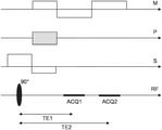
- FIG. 2 shows a schematic (simplified) pulse sequence diagram of a Dixon imaging sequence using bipolar readout magnetic field gradients according to the invention
- FIG. 3 shows a comparison of water images obtained with a conventional water/fat separation (left) and with the method of the invention (right).
- a MR device 1 is shown as a block diagram.
- the device comprises superconducting or resistive main magnet coils 2 such that a substantially uniform, temporally constant main magnetic field B 0 is created along a z-axis through an examination volume.
- the device further comprises a set of (1 st , 2 nd , and—where applicable—3 rd order) shimming coils 2 ′, wherein the current flow through the individual shimming coils of the set 2 ′ is controllable for the purpose of minimizing B 0 deviations within the examination volume.
- a magnetic resonance generation and manipulation system applies a series of RF pulses and switched magnetic field gradients to invert or excite nuclear magnetic spins, induce magnetic resonance, refocus magnetic resonance, manipulate magnetic resonance, spatially and otherwise encode the magnetic resonance, saturate spins, and the like to perform MR imaging.
- a gradient pulse amplifier 3 applies current pulses to selected ones of whole-body gradient coils 4 , 5 and 6 along x, y and z-axes of the examination volume.
- a digital RF frequency transmitter 7 transmits RF pulses or pulse packets, via a send/receive switch 8 and a body RF coil 9 , into the examination volume.
- a typical MR imaging sequence is composed of a packet of RF pulse segments of short duration which, together with any applied magnetic field gradients, achieve a selected manipulation of nuclear magnetic resonance.
- the RF pulses are used to saturate resonance, excite resonance, invert magnetization, refocus resonance, or manipulate resonance and select a portion of a body 10 positioned in the examination volume.
- the MR signals are also picked up by the body RF coil 9 .
- a set of local array RF coils 11 , 12 , 13 are placed contiguous to the region selected for imaging.
- the array coils 11 , 12 , 13 can be used to receive MR signals induced by RF transmissions via the body RF coil.
- the resultant MR signals are picked up by the body RF coil 9 and/or by the array RF coils 11 , 12 , 13 and demodulated by a receiver 14 preferably including a preamplifier (not shown).
- the receiver 14 is connected to the RF coils 9 , 11 , 12 and 13 via the send/receive switch 8 .
- a host computer 15 controls the shimming coils 2 ′ as well as the gradient pulse amplifier 3 and the transmitter 7 to generate the imaging sequences of the invention.
- the receiver 14 receives a single or a plurality of MR data lines in rapid succession following each RF excitation pulse.
- a data acquisition system 16 performs analog-to-digital conversion of the received signals and converts each MR data line to a digital format suitable for further processing. In modern MR devices the data acquisition system 16 is a separate computer which is specialized in acquisition of raw image data.
- the digital raw image data are reconstructed into an image representation by a reconstruction processor 17 which applies a Fourier transform or other appropriate reconstruction algorithms, such as SENSE.
- the MR image may represent a planar slice through the patient, an array of parallel planar slices, a three-dimensional volume, or the like.
- the image is then stored in an image memory where it may be accessed for converting slices, projections, or other portions of the image representation into appropriate format for visualization, for example via a video monitor 18 which provides a man-readable display of the resultant MR image.
- the host computer 15 and the reconstruction processor 17 are programmed to execute the method of the invention as described above and in the following.
- FIG. 2 a schematic pulse sequence diagram of a dual-echo Dixon imaging sequence using bipolar readout magnetic field gradients according to the invention is depicted.
- the diagram shows switched magnetic field gradients in the frequency-encoding direction (M), the phase-encoding direction (P) and the slice-selection direction (S).
- the diagram shows an RF excitation pulse as well as the time intervals during which echo signals are acquired, designated by ACQ 1 and ACQ 2 .
- the diagram covers the acquisition of one pair of echo signals. A number of such pairs of echo signals is acquired by multiple repetitions of the depicted sequence using different phase encodings (P) to completely cover the required region of k-space.
- Each pair of echo signals is acquired using a corresponding pair of readout magnetic field gradients (M) with opposed polarity.
- the timing and amplitudes of the bipolar readout magnetic field gradients are chosen to shift the acquisition windows ACQ 1 and ACQ 2 of the echo signals such that different echo times TE 1 and TE 2 and correspondingly different phase offsets of the signal contributions from water protons and fat protons are provided.
- One set of echo signals is acquired at echo time TE 1 and another set of echo signals is acquired at echo time TE 2 .
- the Dixon-type separation of these signal contributions is based on the resulting phase offsets in the final step of reconstruction of a water and/or a fat image.
- a first image is reconstructed from the echo signals attributed to the first echo time TE 1 and a second image is reconstructed from the echo signals attributed to the second echo time TE 2 .
- a signal model is used for water/fat separation which includes the signal contributions from water and fat at each voxel position, a phase offset between water and fat induced by the difference in chemical shift and a (main field inhomogeneity-induced) phase error. Potential solutions for the phase error, as well as corresponding potential solutions for the water and the fat signal, are computed.
- FIG. 3 shows a comparison of water images obtained with a conventional two-point water/fat separation (left) and the water/fat separation technique of the invention (right).
- the white arrow points at an incomplete fat suppression at a tissue/air interface using the conventional technique. This artifact is not present in the right image which is obtained by the method of the invention.
Landscapes
- Physics & Mathematics (AREA)
- General Physics & Mathematics (AREA)
- High Energy & Nuclear Physics (AREA)
- Condensed Matter Physics & Semiconductors (AREA)
- Nuclear Medicine, Radiotherapy & Molecular Imaging (AREA)
- Radiology & Medical Imaging (AREA)
- Engineering & Computer Science (AREA)
- Signal Processing (AREA)
- General Health & Medical Sciences (AREA)
- Health & Medical Sciences (AREA)
- Spectroscopy & Molecular Physics (AREA)
- Optics & Photonics (AREA)
- Magnetic Resonance Imaging Apparatus (AREA)
Applications Claiming Priority (4)
| Application Number | Priority Date | Filing Date | Title |
|---|---|---|---|
| EP17193731.1A EP3462204A1 (en) | 2017-09-28 | 2017-09-28 | Dixon-type water/fat separation mr imaging with improved fat shift correction |
| EP17193731 | 2017-09-28 | ||
| EP17193731.1 | 2017-09-28 | ||
| PCT/EP2018/076035 WO2019063574A1 (en) | 2017-09-28 | 2018-09-26 | DIXON TYPE WATER / GREASE SEPARATION MAGNETIC RESONANCE IMAGING WITH ENHANCED FAT OFFSET CORRECTION |
Publications (2)
| Publication Number | Publication Date |
|---|---|
| US20200300948A1 US20200300948A1 (en) | 2020-09-24 |
| US11226385B2 true US11226385B2 (en) | 2022-01-18 |
Family
ID=59974326
Family Applications (1)
| Application Number | Title | Priority Date | Filing Date |
|---|---|---|---|
| US16/651,398 Active US11226385B2 (en) | 2017-09-28 | 2018-09-26 | Dixon type water/fat separation MR imaging with improved fat shift correction |
Country Status (5)
| Country | Link |
|---|---|
| US (1) | US11226385B2 (enExample) |
| EP (2) | EP3462204A1 (enExample) |
| JP (1) | JP7237066B2 (enExample) |
| CN (1) | CN111164444B (enExample) |
| WO (1) | WO2019063574A1 (enExample) |
Cited By (1)
| Publication number | Priority date | Publication date | Assignee | Title |
|---|---|---|---|---|
| US12540992B2 (en) * | 2022-04-04 | 2026-02-03 | Canon Medical Systems Corporation | Data processing apparatus and MRI apparatus |
Families Citing this family (1)
| Publication number | Priority date | Publication date | Assignee | Title |
|---|---|---|---|---|
| US11163027B2 (en) * | 2019-06-05 | 2021-11-02 | Canon Medical Systems Corporation | Magnetic resonance imaging apparatus and magnetic resonance imaging method |
Citations (8)
| Publication number | Priority date | Publication date | Assignee | Title |
|---|---|---|---|---|
| US20100244822A1 (en) | 2009-03-31 | 2010-09-30 | General Electric Company | Method and system to perform phase correction for species separation in magnetic resonance imaging |
| US20110091090A1 (en) | 2008-04-17 | 2011-04-21 | Olof Dahlqvist Leinhard | Improvement in magnetic resonance imaging relating to correction of chemical shift artifact and intensity inhomogeneity |
| US20120301007A1 (en) | 2010-03-03 | 2012-11-29 | Hitachi Medical Corporation | Magnetic resonance imaging device |
| US20160187447A1 (en) | 2014-12-29 | 2016-06-30 | General Electric Company | Method and apparatus for separating chemical species in magnetic resonance imaging |
| US20160231405A1 (en) * | 2013-09-16 | 2016-08-11 | Koninklijke Philips N.V. | Mr imaging with dixon-type water/fat separation |
| US20160313423A1 (en) | 2013-12-19 | 2016-10-27 | Koninklijke Philips N.V. | Mri with dixon-type water/fat separation with estimation of the main magnetic field variations |
| US20170038446A1 (en) | 2014-04-24 | 2017-02-09 | Junmin LIU | Systems and methods for field mapping in magnetic resonance imaging |
| US20180259607A1 (en) * | 2017-03-10 | 2018-09-13 | Maria Drangova | Method for dixon mri, multi-contrast imaging and multi-parametric mapping with a single multi-echo gradient-recalled echo acquisition |
Family Cites Families (3)
| Publication number | Priority date | Publication date | Assignee | Title |
|---|---|---|---|---|
| WO2013001415A1 (en) * | 2011-06-28 | 2013-01-03 | Koninklijke Philips Electronics N.V. | Mri with separation of different chemical species using a spectral model |
| EP2992351B1 (en) * | 2013-04-03 | 2019-08-07 | Koninklijke Philips N.V. | Dixon-type water/fat separation mri using high-snr in-phase image and lower-snr at least partially out-of-phase image |
| CN107076819B (zh) * | 2014-09-26 | 2020-01-10 | 皇家飞利浦有限公司 | 具有对流伪影的抑制的Dixon MR成像 |
-
2017
- 2017-09-28 EP EP17193731.1A patent/EP3462204A1/en not_active Withdrawn
-
2018
- 2018-09-26 US US16/651,398 patent/US11226385B2/en active Active
- 2018-09-26 EP EP18773455.3A patent/EP3688479B1/en active Active
- 2018-09-26 JP JP2020517151A patent/JP7237066B2/ja active Active
- 2018-09-26 CN CN201880062445.9A patent/CN111164444B/zh active Active
- 2018-09-26 WO PCT/EP2018/076035 patent/WO2019063574A1/en not_active Ceased
Patent Citations (8)
| Publication number | Priority date | Publication date | Assignee | Title |
|---|---|---|---|---|
| US20110091090A1 (en) | 2008-04-17 | 2011-04-21 | Olof Dahlqvist Leinhard | Improvement in magnetic resonance imaging relating to correction of chemical shift artifact and intensity inhomogeneity |
| US20100244822A1 (en) | 2009-03-31 | 2010-09-30 | General Electric Company | Method and system to perform phase correction for species separation in magnetic resonance imaging |
| US20120301007A1 (en) | 2010-03-03 | 2012-11-29 | Hitachi Medical Corporation | Magnetic resonance imaging device |
| US20160231405A1 (en) * | 2013-09-16 | 2016-08-11 | Koninklijke Philips N.V. | Mr imaging with dixon-type water/fat separation |
| US20160313423A1 (en) | 2013-12-19 | 2016-10-27 | Koninklijke Philips N.V. | Mri with dixon-type water/fat separation with estimation of the main magnetic field variations |
| US20170038446A1 (en) | 2014-04-24 | 2017-02-09 | Junmin LIU | Systems and methods for field mapping in magnetic resonance imaging |
| US20160187447A1 (en) | 2014-12-29 | 2016-06-30 | General Electric Company | Method and apparatus for separating chemical species in magnetic resonance imaging |
| US20180259607A1 (en) * | 2017-03-10 | 2018-09-13 | Maria Drangova | Method for dixon mri, multi-contrast imaging and multi-parametric mapping with a single multi-echo gradient-recalled echo acquisition |
Non-Patent Citations (12)
| Title |
|---|
| Ben et al. "Correction of Fat-Water Swaps in Dixon MRI" Network and Parallel Computing, p. 536-543 (2016). |
| Doneva et al. "Compressed Sensing for Chemical Shift Based Water Fat Separation" Magnetic Resonance in Med. 24 p. 1749-1759 (2010). |
| Eggers H, et al. Chemical shift encoding-based water-fat separation methods. J Magn Reson Im-aging 2014; 40:251-268. |
| Eggers H, et al. Dual-echo Dixon imaging with flexible choice of echo times. Magn Reson Med 2011; 65:96-107. |
| Huanzhou Yu et al.. Combination of Complex-Based and Magnitude-Based Multiecho Water-Fat Separation for Accurate Quantification of Fat-Fraction; Magnetic Resonance in Med. 66 p. 199-206 (2011). |
| Huanzhou Yu et al.Phase and Amplitude Correction for Multi-Echo Water-Fat Separation With Bipolar Acquisitions J Magn Reson Imaging. May 2010 ; 31(5): 1264-1271. doi:10.01002/jmri.22111. |
| International Search Report from PCT/EP2018/076035 dated Dec. 19, 2018. |
| Jingfei Ma et al. "Linear Phase-Error Correction for Improved Water and Fat Separation in Dual-Echo Dixon Techniques" Magnetic Resonance in Med. 60 p. 1250-1255 (2008). |
| Junmin Liu et al., "Method of B0 Mapping with Magnitude-Based Correction for Bipolar Two-Point Dixon Cardiac MRI" Magnetic Resonance in Med. (2016). |
| Lu W, et al. Water-fat separation with bipolar multi-echo sequences. Magn Reson Med 2008; 60: 198-209. |
| Sharma et al. "Improving Chemical Shift Encoded Water-Fat Separation using Object Based Information of the Magnetic Field Inhomogeneity" Magnetic Resonance in Med. vol. 73, No. 2 p. 597-604 (2014). |
| Tobias Romu et al., "Robust Water Fat Separated Dual-Echo MRI by Phase-Sensitive Reconstruction" Magnetic Resonance in Med. (2016). |
Cited By (1)
| Publication number | Priority date | Publication date | Assignee | Title |
|---|---|---|---|---|
| US12540992B2 (en) * | 2022-04-04 | 2026-02-03 | Canon Medical Systems Corporation | Data processing apparatus and MRI apparatus |
Also Published As
| Publication number | Publication date |
|---|---|
| EP3462204A1 (en) | 2019-04-03 |
| CN111164444A (zh) | 2020-05-15 |
| JP2020534916A (ja) | 2020-12-03 |
| US20200300948A1 (en) | 2020-09-24 |
| JP7237066B2 (ja) | 2023-03-10 |
| EP3688479B1 (en) | 2024-02-14 |
| EP3688479A1 (en) | 2020-08-05 |
| WO2019063574A1 (en) | 2019-04-04 |
| CN111164444B (zh) | 2023-04-04 |
Similar Documents
| Publication | Publication Date | Title |
|---|---|---|
| US11041926B2 (en) | Dixon-type water/fat separation MR imaging | |
| US10996301B2 (en) | Dual-echo dixon-type water/fat separation MR imaging | |
| EP3004908A1 (en) | Parallel mri with b0 distortion correction and multi-echo dixon water-fat separation using regularised sense reconstruction | |
| US11327133B2 (en) | Dixon-type water/fat separation MR imaging | |
| US10859652B2 (en) | MR imaging with dixon-type water/fat separation | |
| US20220057467A1 (en) | Epi mr imaging with distortion correction | |
| US12360188B2 (en) | Dixon-type water/fat separation MR imaging | |
| WO2018114554A1 (en) | Dixon-type water/fat separation mr imaging | |
| US11226385B2 (en) | Dixon type water/fat separation MR imaging with improved fat shift correction | |
| US12392851B2 (en) | Dixon-type water/fat separation MR imaging | |
| US11940517B2 (en) | MR imaging using Dixon-type water/fat separation with suppression of flow-induced leakage and/or swapping artifacts | |
| EP4597148A1 (en) | Dixon type water/fat separation mr imaging | |
| RU2773486C2 (ru) | Магнитно-резонансная визуализация с разделением вода/жир методом диксона |
Legal Events
| Date | Code | Title | Description |
|---|---|---|---|
| AS | Assignment |
Owner name: KONINKLIJKE PHILIPS N.V., NETHERLANDS Free format text: ASSIGNMENT OF ASSIGNORS INTEREST;ASSIGNOR:EGGERS, HOLGER;REEL/FRAME:052241/0823 Effective date: 20181022 |
|
| FEPP | Fee payment procedure |
Free format text: ENTITY STATUS SET TO UNDISCOUNTED (ORIGINAL EVENT CODE: BIG.); ENTITY STATUS OF PATENT OWNER: LARGE ENTITY |
|
| STPP | Information on status: patent application and granting procedure in general |
Free format text: APPLICATION DISPATCHED FROM PREEXAM, NOT YET DOCKETED |
|
| STPP | Information on status: patent application and granting procedure in general |
Free format text: DOCKETED NEW CASE - READY FOR EXAMINATION |
|
| STPP | Information on status: patent application and granting procedure in general |
Free format text: NON FINAL ACTION MAILED |
|
| STPP | Information on status: patent application and granting procedure in general |
Free format text: RESPONSE TO NON-FINAL OFFICE ACTION ENTERED AND FORWARDED TO EXAMINER |
|
| STPP | Information on status: patent application and granting procedure in general |
Free format text: NOTICE OF ALLOWANCE MAILED -- APPLICATION RECEIVED IN OFFICE OF PUBLICATIONS |
|
| STPP | Information on status: patent application and granting procedure in general |
Free format text: PUBLICATIONS -- ISSUE FEE PAYMENT VERIFIED |
|
| STCF | Information on status: patent grant |
Free format text: PATENTED CASE |
|
| MAFP | Maintenance fee payment |
Free format text: PAYMENT OF MAINTENANCE FEE, 4TH YEAR, LARGE ENTITY (ORIGINAL EVENT CODE: M1551); ENTITY STATUS OF PATENT OWNER: LARGE ENTITY Year of fee payment: 4 |