US11225775B2 - Cycle time calibration - Google Patents
Cycle time calibration Download PDFInfo
- Publication number
- US11225775B2 US11225775B2 US16/452,720 US201916452720A US11225775B2 US 11225775 B2 US11225775 B2 US 11225775B2 US 201916452720 A US201916452720 A US 201916452720A US 11225775 B2 US11225775 B2 US 11225775B2
- Authority
- US
- United States
- Prior art keywords
- pressure
- cycle time
- sensed
- timer
- processor
- Prior art date
- Legal status (The legal status is an assumption and is not a legal conclusion. Google has not performed a legal analysis and makes no representation as to the accuracy of the status listed.)
- Expired - Fee Related, expires
Links
Images


Classifications
-
- E—FIXED CONSTRUCTIONS
- E02—HYDRAULIC ENGINEERING; FOUNDATIONS; SOIL SHIFTING
- E02F—DREDGING; SOIL-SHIFTING
- E02F9/00—Component parts of dredgers or soil-shifting machines, not restricted to one of the kinds covered by groups E02F3/00 - E02F7/00
-
- E—FIXED CONSTRUCTIONS
- E02—HYDRAULIC ENGINEERING; FOUNDATIONS; SOIL SHIFTING
- E02F—DREDGING; SOIL-SHIFTING
- E02F9/00—Component parts of dredgers or soil-shifting machines, not restricted to one of the kinds covered by groups E02F3/00 - E02F7/00
- E02F9/26—Indicating devices
- E02F9/264—Sensors and their calibration for indicating the position of the work tool
-
- E—FIXED CONSTRUCTIONS
- E02—HYDRAULIC ENGINEERING; FOUNDATIONS; SOIL SHIFTING
- E02F—DREDGING; SOIL-SHIFTING
- E02F9/00—Component parts of dredgers or soil-shifting machines, not restricted to one of the kinds covered by groups E02F3/00 - E02F7/00
- E02F9/20—Drives; Control devices
- E02F9/22—Hydraulic or pneumatic drives
- E02F9/2203—Arrangements for controlling the attitude of actuators, e.g. speed, floating function
-
- E—FIXED CONSTRUCTIONS
- E02—HYDRAULIC ENGINEERING; FOUNDATIONS; SOIL SHIFTING
- E02F—DREDGING; SOIL-SHIFTING
- E02F9/00—Component parts of dredgers or soil-shifting machines, not restricted to one of the kinds covered by groups E02F3/00 - E02F7/00
- E02F9/02—Travelling-gear, e.g. associated with slewing gears
- E02F9/04—Walking gears moving the dredger forward step-by-step
-
- E—FIXED CONSTRUCTIONS
- E02—HYDRAULIC ENGINEERING; FOUNDATIONS; SOIL SHIFTING
- E02F—DREDGING; SOIL-SHIFTING
- E02F9/00—Component parts of dredgers or soil-shifting machines, not restricted to one of the kinds covered by groups E02F3/00 - E02F7/00
- E02F9/08—Superstructures; Supports for superstructures
-
- E—FIXED CONSTRUCTIONS
- E02—HYDRAULIC ENGINEERING; FOUNDATIONS; SOIL SHIFTING
- E02F—DREDGING; SOIL-SHIFTING
- E02F9/00—Component parts of dredgers or soil-shifting machines, not restricted to one of the kinds covered by groups E02F3/00 - E02F7/00
- E02F9/20—Drives; Control devices
-
- E—FIXED CONSTRUCTIONS
- E02—HYDRAULIC ENGINEERING; FOUNDATIONS; SOIL SHIFTING
- E02F—DREDGING; SOIL-SHIFTING
- E02F9/00—Component parts of dredgers or soil-shifting machines, not restricted to one of the kinds covered by groups E02F3/00 - E02F7/00
- E02F9/20—Drives; Control devices
- E02F9/22—Hydraulic or pneumatic drives
- E02F9/2221—Control of flow rate; Load sensing arrangements
-
- E—FIXED CONSTRUCTIONS
- E02—HYDRAULIC ENGINEERING; FOUNDATIONS; SOIL SHIFTING
- E02F—DREDGING; SOIL-SHIFTING
- E02F9/00—Component parts of dredgers or soil-shifting machines, not restricted to one of the kinds covered by groups E02F3/00 - E02F7/00
- E02F9/20—Drives; Control devices
- E02F9/22—Hydraulic or pneumatic drives
- E02F9/2246—Control of prime movers, e.g. depending on the hydraulic load of work tools
-
- E—FIXED CONSTRUCTIONS
- E02—HYDRAULIC ENGINEERING; FOUNDATIONS; SOIL SHIFTING
- E02F—DREDGING; SOIL-SHIFTING
- E02F9/00—Component parts of dredgers or soil-shifting machines, not restricted to one of the kinds covered by groups E02F3/00 - E02F7/00
- E02F9/20—Drives; Control devices
- E02F9/22—Hydraulic or pneumatic drives
- E02F9/226—Safety arrangements, e.g. hydraulic driven fans, preventing cavitation, leakage, overheating
-
- E—FIXED CONSTRUCTIONS
- E02—HYDRAULIC ENGINEERING; FOUNDATIONS; SOIL SHIFTING
- E02F—DREDGING; SOIL-SHIFTING
- E02F9/00—Component parts of dredgers or soil-shifting machines, not restricted to one of the kinds covered by groups E02F3/00 - E02F7/00
- E02F9/20—Drives; Control devices
- E02F9/22—Hydraulic or pneumatic drives
- E02F9/2264—Arrangements or adaptations of elements for hydraulic drives
- E02F9/2267—Valves or distributors
-
- E—FIXED CONSTRUCTIONS
- E02—HYDRAULIC ENGINEERING; FOUNDATIONS; SOIL SHIFTING
- E02F—DREDGING; SOIL-SHIFTING
- E02F9/00—Component parts of dredgers or soil-shifting machines, not restricted to one of the kinds covered by groups E02F3/00 - E02F7/00
- E02F9/20—Drives; Control devices
- E02F9/22—Hydraulic or pneumatic drives
- E02F9/2278—Hydraulic circuits
- E02F9/2296—Systems with a variable displacement pump
-
- G—PHYSICS
- G07—CHECKING-DEVICES
- G07C—TIME OR ATTENDANCE REGISTERS; REGISTERING OR INDICATING THE WORKING OF MACHINES; GENERATING RANDOM NUMBERS; VOTING OR LOTTERY APPARATUS; ARRANGEMENTS, SYSTEMS OR APPARATUS FOR CHECKING NOT PROVIDED FOR ELSEWHERE
- G07C5/00—Registering or indicating the working of vehicles
- G07C5/008—Registering or indicating the working of vehicles communicating information to a remotely located station
-
- G—PHYSICS
- G07—CHECKING-DEVICES
- G07C—TIME OR ATTENDANCE REGISTERS; REGISTERING OR INDICATING THE WORKING OF MACHINES; GENERATING RANDOM NUMBERS; VOTING OR LOTTERY APPARATUS; ARRANGEMENTS, SYSTEMS OR APPARATUS FOR CHECKING NOT PROVIDED FOR ELSEWHERE
- G07C5/00—Registering or indicating the working of vehicles
- G07C5/08—Registering or indicating performance data other than driving, working, idle, or waiting time, with or without registering driving, working, idle or waiting time
- G07C5/0808—Diagnosing performance data
-
- G—PHYSICS
- G07—CHECKING-DEVICES
- G07C—TIME OR ATTENDANCE REGISTERS; REGISTERING OR INDICATING THE WORKING OF MACHINES; GENERATING RANDOM NUMBERS; VOTING OR LOTTERY APPARATUS; ARRANGEMENTS, SYSTEMS OR APPARATUS FOR CHECKING NOT PROVIDED FOR ELSEWHERE
- G07C5/00—Registering or indicating the working of vehicles
- G07C5/08—Registering or indicating performance data other than driving, working, idle, or waiting time, with or without registering driving, working, idle or waiting time
- G07C5/0816—Indicating performance data, e.g. occurrence of a malfunction
-
- E—FIXED CONSTRUCTIONS
- E02—HYDRAULIC ENGINEERING; FOUNDATIONS; SOIL SHIFTING
- E02F—DREDGING; SOIL-SHIFTING
- E02F3/00—Dredgers; Soil-shifting machines
- E02F3/04—Dredgers; Soil-shifting machines mechanically-driven
- E02F3/28—Dredgers; Soil-shifting machines mechanically-driven with digging tools mounted on a dipper- or bucket-arm, i.e. there is either one arm or a pair of arms, e.g. dippers, buckets
- E02F3/36—Component parts
- E02F3/42—Drives for dippers, buckets, dipper-arms or bucket-arms
- E02F3/43—Control of dipper or bucket position; Control of sequence of drive operations
- E02F3/435—Control of dipper or bucket position; Control of sequence of drive operations for dipper-arms, backhoes or the like
- E02F3/438—Memorising movements for repetition, e.g. play-back capability
Definitions
- the present disclosure relates to work vehicles and time calibration of one or more functions of the work vehicles.
- the disclosure provides a work vehicle including a chassis, a ground engaging implement configured to move the chassis along a ground surface, a boom including a first boom portion connected to the chassis and a second boom portion, an arm including a first arm portion connected to the second boom portion and a second arm portion, and a bucket connected to the second arm portion.
- a first actuator includes a first portion connected to the chassis and a second portion connected to the boom. The first actuator rotates the boom with respect to the chassis.
- a second actuator includes a first portion connected to the boom and a second portion connected to the arm. The second actuator rotates the arm with respect to the boom.
- a third actuator includes a first portion connected to the arm and a second portion connected to the bucket. The third actuator rotates the bucket with respect to the arm.
- a processor calculates a first cycle time of operation of the first actuator, and analyzes if the calculated first cycle time is valid. If the first cycle time is valid, the processor communicates the calculated first cycle time to a user, and if the first cycle time is not valid, the processor repeats the calculation of the first cycle time of operation of the first actuator.
- the disclosure provides a method for calculating a cycle time for a work vehicle having a chassis, a boom rotatably connected to the chassis via a first actuator, an arm rotatably connected to the boom via a second actuator, and a bucket rotatably connected to the arm via a third actuator.
- the method includes sensing a first pressure proximate the first actuator, comparing the sensed first pressure to a threshold pressure, sensing a second pressure proximate the second actuator, comparing the sensed second pressure to the threshold pressure, sensing a third pressure proximate the third actuator, and comparing the sensed third pressure to the threshold pressure.
- the method further includes starting a timer if all of the following conditions occur: if the first sensed pressure is greater than the threshold pressure, if the sensed second pressure is less than the threshold pressure, and if the sensed third pressure is less than the threshold pressure.
- the method also includes further sensing the first pressure after starting the timer, further sensing the second pressure after starting the timer, further sensing the third pressure after staring time the timer, and stopping the timer when any of the following conditions occur: if the sensed first pressure is less than the threshold pressure, if the sensed second pressure is greater than the threshold pressure, and if the sensed third pressure is greater than the threshold pressure.
- the method further includes communicating a cycle time to a processor, determining with the processor if the cycle time is valid, and storing the cycle time with the processor if the cycle time is determined to be valid.
- the disclosure provides a method for calculating a cycle time for a work vehicle having a chassis, a boom rotatably connected to the chassis via a first actuator, and a bucket rotatably connected to the boom via a second actuator.
- the method includes sensing a first pressure proximate the first actuator, comparing the sensed first pressure to a threshold pressure, sensing a second pressure proximate the second actuator, comparing the sensed second pressure to the threshold pressure, and starting timer if the following conditions occur: if the first sensed pressure is less than the threshold pressure, and if the sensed second pressure is greater than the threshold pressure.
- the method further comprising further sensing the first pressure after starting the timer, further sensing the second pressure after starting the timer, and stopping the timer when either of the following conditions occur: if the sensed first pressure is greater than the threshold pressure, and if the sensed second pressure is less than the threshold pressure.
- the method further comprising communicating a cycle time to a processor, determining with the processor if the cycle time is valid, and storing the cycle time if the cycle time is determined to be valid.
- FIG. 1 is a perspective view of a work vehicle according to some embodiments.
- FIG. 2 is a schematic view of a hydraulic circuit according to some embodiments.
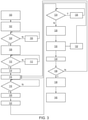
- FIG. 3 is a flow chart showing one possible method of operation.
- FIG. 4 is a graph of an example calculation of pressure over time.
- FIG. 1 illustrates an off-highway machine, such as an excavator 10 , having a chassis 14 and a ground-engaging implement (e.g., tracks or crawler mechanisms 18 ) for supporting and propelling the chassis 14 and therefore the machine 10 along a surface.
- the crawler mechanisms 18 are oriented parallel to a longitudinal axis A of the chassis 14 , which coincides with a forward direction of travel of the machine 10 during operation.
- each crawler mechanism 18 includes a drive sprocket 42 , an undercarriage frame 46 , and a track 50 .
- the drive sprocket 42 is driven by a prime mover 54 and engages the track 50 .
- the track 50 is driven in an endless loop around the drive sprocket 42 and the undercarriage frame 46 .
- the illustrated machine 10 further includes an operator cab 22 , a boom 30 , an arm 32 , a bucket 34 supported on an end of the arm 32 , a processor 56 , and a user interface 58 .
- the boom 30 includes a first end that is pivotally connected to the chassis 14 and a second distal end.
- First and second boom cylinders 60 a , 60 b are connected to the chassis 14 and to the boom 30 .
- the first and second arm cylinders 60 a , 60 b are operable to pivot the boom 30 with respect to the chassis 14 .
- the arm 32 includes a first end pivotally connected to the second end of the boom 30 and a second distal end.
- An arm cylinder 62 is connected to the boom 30 and to the arm 32 and is operable to pivot the arm 32 with respect to the boom 30 .
- the bucket 34 is connected to the distal end of the arm 32 .
- a bucket cylinder 64 is connected to the arm 32 and to the bucket 34 via a pivot arm 36 and is operable to pivot the bucket 34 with respect to the arm 32 via the pivot arm 36 .
- the cylinders 60 a , 60 b , 62 and 64 are hydraulic cylinders, but other configurations, such as pneumatic cylinders can be utilized.
- the off-highway machine 10 is illustrated and described as an excavator, it is understood that the off-highway machine 10 may have a different form, such as a loader, a dozer, a motor grader, a scraper, or another type of construction, mining, agricultural, or utility machine.
- the work attachment is illustrated and described as a bucket, it is understood that the work attachment may have a different form, such as an auger, a breaker, a ripper, a grapple, or some other type of attachment for digging, breaking, handling, carrying, dumping or otherwise engaging dirt or other material.
- the work attachment may be detachable from the arm 32 to permit another type of work attachment to be connected to the arm 32 .
- FIG. 2 is a schematic according to some embodiments.
- FIG. 2 illustrates that the boom cylinders 60 a / 60 b are connected to the chassis 14 at a first end and are connected to the boom 30 at a second end.
- the first end of each of the boom cylinders 60 a / 60 b is fluidly connected to a first valve 70 and a second valve 72 and the second end of each of the boom cylinders 60 a / 60 b is fluidly connected to the first valve 70 .
- the boom cylinders 60 a and 60 b are substantially identical and fluidly connected in parallel to the first valve 70 and to the second valve 72 .
- a pump 74 moves fluid from a reservoir 76 through the first valve 70 and optionally through the second valve 72 into the first end of each of the boom cylinders 60 a / 60 b and fluid is moved from the second end of each of the boom cylinders 60 a / 60 b through the first valve 70 into the reservoir to pivot the boom 30 upwards (counterclockwise in FIG. 2 ).
- the pump 74 moves fluid from the reservoir 76 through the first valve 70 into the second end of each of the boom cylinders 60 a / 60 b and fluid is moved from the first end of each of the boom cylinders 60 a / 60 b through the first valve 70 into the reservoir to pivot the boom 30 downwards (clockwise in FIG. 2 ).
- a first end of the arm cylinder 62 is connected to the boom 30 and a second end of the arm cylinder 62 is connected to the arm 32 .
- the pump 74 moves fluid from the reservoir 76 through a third valve 78 and optionally through a fourth valve 80 into the first end of the arm cylinder 62 and fluid is moved from the second end of the arm cylinder 62 through the third valve 78 and optionally through the fourth valve 80 in the reservoir to pivot the arm 32 upwards (counterclockwise in FIG. 2 ).
- the pump 74 moves fluid from the reservoir 76 through the third valve 78 and optionally through the fourth valve 80 into the second end of the arm cylinders 62 and fluid is moved from the first end of the arm cylinder 62 through the third valve 78 and optionally through the fourth valve 80 into the reservoir to pivot the arm 32 downwards (clockwise in FIG. 2 ).
- a first end of the bucket cylinder 64 is connected to the arm 32 and a second end of the bucket cylinder 64 is connected to the pivot arm 36 .
- the pump 74 moves fluid from the reservoir 76 through a fifth valve 82 into the first end of the bucket cylinder 64 and fluid is moved from the second end of the bucket cylinder 64 through the fifth valve 82 into the reservoir 76 to pivot the bucket 34 upward (clockwise in FIG. 2 ).
- the pump moves fluid from the reservoir 76 through the fifth valve 82 into the second end of the bucket cylinder 64 and fluid is moved from the first end of the bucket cylinder 64 through the fifth valve 82 into the reservoir to pivot the bucket 34 downward (counterclockwise in FIG. 2 ).
- a first pilot control 86 is fluidly connected to both ends of the first valve 70 , one end of the second valve 72 and to both ends of the fifth valve 82 .
- the first pilot control 86 is configured to actuate the first valve 70 , the second valve 72 and the fifth valve 82 .
- Each of the fluid flow lines between the first valve 70 and the first pilot control 86 as well as the fluid lines between the fifth valve 82 and the first pilot control 86 includes a pressure sensor (shown by a circle with a diagonal arrow) configured to sense a fluid pressure in the respective flow line.
- a second pilot control 88 is fluidly connected to both ends of the third valve 78 and to both ends of the fourth valve 80 .
- the second pilot control 88 is configured to actuate the third valve 78 and the fourth valve 80 .
- Both of the fluid flow lines between the second pilot control 88 and the third valve 78 include a pressure sensor (shown by a circle with a diagonal arrow) configured to sense a fluid pressure in the respective flow line.
- the cylinders 60 a , 60 b , 62 and 64 , the valves 70 , 72 , 78 , 80 and 82 , and the pressure sensors are all electrically coupled to the processor 56 .
- FIG. 3 illustrates one possible method of cycle time calibration according to some embodiments.
- Calibration testing is initiated by the operator entering a calibration application and selecting a cycle time option via the user interface 58 .
- the user selects one of the following functions to test: (1) the boom cylinders 60 a and 60 b , (2) the arm cylinder 62 or (3) the bucket cylinder 64 .
- the processor 56 checks for system faults that would result in an invalid calibration. If no faults are uncovered, calibration continues to step 104 .
- step 104 the temperature of hydraulic oil is also sensed and operation is permitted in safe state if the sensed temperature is above a pre-determined temperature. If the sensed temperature is too low, the machine is warmed up at step 106 until the temperature rises above the pre-determined temperature. If the sensed temperature is above the pre-determined temperature, operation proceeds to step 108 .
- the processor 56 sends signals to set the engine speed to maximum throttle, the mode to high power mode in which the machine will operate at maximum speed, work mode is set to dig and the automatic idle is deactivated. These signals from the processor 56 put the machine in a known state where variables relating to engine speed and performance are controlled. Therefore, the processor 56 confirms that the machine is ready to begin calibration at which time machine settings such as power mode, pressure boost and engine speed could be overridden by the processor 56 at step 108 .
- the processor 56 enquires if the pilot lever has been raised.
- the pilot lever is controlled by the operator in the operator cab 22 and corresponds to the selected boom cylinders 60 a / 60 b . If the pilot lever has not been raised, the operator is instructed to raise the pilot lever at step 112 . If the pilot lever has been raised, operation moves to step 114 at which the operator moves the appropriate joystick to extend the selected boom cylinders 60 a / 60 b.
- a pilot pressure at the boom pressure sensors is sensed and communicated to the processor 56 .
- the processor compares the sensed pressure to a first threshold pressure. If the sensed pressure is greater than the first threshold pressure, operation moves to step 120 . If the sensed pressure is less than or equal to the threshold pressure, operation returns to step 116 at which the pilot pressure is sensed.
- a cycle time clock is started.
- a first pilot pressure at the first valve 70 is sensed, a second pilot pressure at the third valve 78 is sensed, a third pilot pressure at the fifth valve 82 is sensed, and a change in pump pressure is sensed at the pump 74 .
- the sensed pressures are compared to respective threshold pressures. Operation moves to step 126 , at which the processor continues incrementing the cycle time, if all of the following conditions occur:
- the first sensed pressure is greater than the first threshold pressure
- the second pressure is less than the second threshold pressure
- the third pressures is less than a third threshold pressure
- the sensed change in pump pressure is less than the pressure change threshold.
- the first threshold pressure is identical to the second threshold pressure. In other embodiments, the first threshold pressure is greater than the second threshold pressure. In some embodiments the second threshold pressure is identical to the third threshold pressure. In other embodiments, the second threshold pressure is greater than the third threshold pressure. Operation moves to step 128 , at which the cycle time is stopped, if any of the following conditions occur:
- the first sensed pressure is less than the first threshold pressure
- the second pressure is greater than the second threshold pressure
- the third pressure is greater than the third threshold pressure, or
- the pump pressure change is greater than the pressure change threshold.
- the processor determines if the cycle time is valid.
- the processor records three cycle times and the average of the three cycle times is utilized as the cycle time for purposes of detecting validity. Some of the causes of an invalid cycle time are the operator discontinuing operation of the cycle time, the pump pressure exceeding a threshold pressure, or the rate of change of pump pressure exceeds a threshold rate.
- the cycle time is determined to be invalid if any of the following conditions occurred during the cycle time:
- one or more diagnostic error codes were generated.
- step 132 determines that the cycle time is invalid
- step 132 determines that the cycle time is discarded and operation returns to step 116 to record another cycle time.
- step 134 determines if a sufficient number of cycle times have been stored. If a sufficient number of cycle times have been stored, operation moves to step 138 . If a sufficient number of cycle times have not been stored, operation returns to step 116 to record another cycle time.
- the processor calculates an average cycle time from the stored cycle times and communicates the calculated average cycle time with the operator and with a network (such as a controller area network, telematics, or other suitable communication network). Then operation moves to step 140 at which the system is returned to normal operation.
- a network such as a controller area network, telematics, or other suitable communication network
- the cycle time mode operation shown in FIG. 3 can be repeated for the arm cylinder 62 and for the bucket cylinder 64 . Only the differences in operation for the arm cylinder 62 and the bucket cylinder 64 will be described in detail.
- the processor 56 enquires if the pilot lever has been raised.
- the pilot lever is controlled by the operator in the operator cab 22 and corresponds to the selected arm cylinders 62 . If the pilot lever has not been raised, the operator is instructed to raise the pilot lever at step 112 . If the pilot lever has been raised, operation moves to step 114 at which the operator moves the appropriate joystick to extend the selected arm cylinder 62 .
- a pilot pressure at the arm pressure sensors is sensed and communicated to the processor 56 .
- the processor compares the sensed pressure to a first threshold pressure. If the sensed pressure is greater than the first threshold pressure, operation moves to step 120 . If the sensed pressure is less than or equal to the first threshold pressure, operation returns to step 116 at which the pilot pressure is sensed.
- a cycle time clock is started.
- a first pilot pressure at the first valve 70 is sensed, a second pilot pressure at the third valve 78 is sensed, a third pilot pressure at the fifth valve 82 is sensed, and a change in pump pressure is sensed at the pump 74 .
- the sensed pressures are compared to respective threshold pressures. Operation moves to step 126 , at which the processor continues incrementing the cycle time, if all of the following conditions occur:
- the first sensed pressure is less than the first threshold pressure
- the second pressure is greater than the second threshold pressure
- the third pressures is less than a third threshold pressure
- the sensed change in pump pressure is less than the pressure change threshold.
- the first threshold pressure is identical to the second threshold pressure. In other embodiments, the first threshold pressure is greater than the second threshold pressure. In some embodiments the second threshold pressure is identical to the third threshold pressure. In other embodiments, the second threshold pressure is greater than the third threshold pressure. Operation moves to step 128 , at which the cycle time is stopped, if any of the following conditions occur:
- the first sensed pressure is greater than the first threshold pressure
- the second pressure is less than the second threshold pressure
- the third pressure is greater than the third threshold pressure, or
- the pump pressure change is greater than the pressure change threshold.
- the processor determines if the cycle time is valid.
- the cycle time is determined to be invalid if any of the following conditions occurred during the cycle time:
- one or more diagnostic error codes were generated.
- step 132 If the processor determines that the cycle time is invalid, operation moves to step 132 .
- the descriptions of steps 132 through 140 for the cycle time calculation of the boom cylinders 60 a / 60 b is identical to the operation of the cycle time calculation of the arm cylinder 62 and the bucket cylinder 64 .
- step 110 if the operator selects the bucket cylinder 64 , the processor 56 enquires if the pilot lever has been raised.
- the pilot lever is controlled by the operator in the operator cab 22 and corresponds to the bucket cylinder 64 . If the pilot lever has not been raised, the operator is instructed to raise the pilot lever at step 112 . If the pilot lever has been raised, operation moves to step 114 at which the operator moves the appropriate joystick to extend the selected bucket cylinder 64 .
- a pilot pressure at the bucket pressure sensors is sensed and communicated to the processor 56 .
- the processor compares the sensed pressure to a first threshold pressure. If the sensed pressure is greater than the first threshold pressure, operation moves to step 120 . If the sensed pressure is less than or equal to the first threshold pressure, operation returns to step 116 at which the pilot pressure is sensed.
- a cycle time clock is started.
- a first pilot pressure at the first valve 70 is sensed, a second pilot pressure at the third valve 78 is sensed and a third pilot pressure at the fifth valve 82 is sensed, and a change in pump pressure is sensed at the pump 74 .
- the sensed pressures are compared to respective threshold pressures. Operation moves to step 126 , at which the processor continues incrementing the cycle time, if all of the following conditions occur:
- the first sensed pressure is less than the second threshold pressure
- the second pressure is less than the third threshold pressure
- the third pressures is greater than the first threshold pressure
- the sensed change in pump pressure is less than the pressure change threshold.
- the first threshold pressure is identical to the second threshold pressure. In other embodiments, the first threshold pressure is greater than the second threshold pressure. In some embodiments the second threshold pressure is identical to the third threshold pressure. In other embodiments, the second threshold pressure is greater than the third threshold pressure. Operation moves to step 128 , at which the cycle time is stopped, if any of the following conditions occur:
- the first sensed pressure is greater than the second threshold pressure
- the second pressure is greater than the third threshold pressure
- the third pressure is less than the first threshold pressure
- the pump pressure change is greater than the pressure change threshold.
- the processor determines if the cycle time is valid.
- the cycle time is determined to be invalid if any of the following conditions occurred during the cycle time:
- one or more diagnostic error codes were generated.
- step 132 If the processor determines that the cycle time is invalid, operation moves to step 132 .
- steps 132 through 140 for the cycle time calculation of the boom cylinders 60 a / 60 b is identical to the operation of the cycle time calculation of the arm cylinder 62 and the bucket cylinder 64 .
- the cycle time calculation can be conducted on a work vehicle having a chassis, a boom connected to the chassis via a boom actuator, and a bucket connected to the boom via a bucket actuator.
- a work vehicle having a chassis, a boom connected to the chassis via a boom actuator, and a bucket connected to the boom via a bucket actuator.
- Such vehicles omit the arm and the arm actuator.
- FIG. 4 illustrates results from one test of the boom cylinders.
- the solid line shows the boom raise pilot pressure which is sensed near the boom joystick.
- the dotted line is the boom cylinder stroke which can be sensed by a position sensor and illustrates the position of the piston within the boom cylinder.
- the dashed line illustrates the pump pressure which is sensed by one or more pressure sensors adjacent the pump.
- the piston begins to move from one end of its stroke within the boom cylinder (at about 40% in the graph)
- the boom raise pilot pressure increases dramatically and the pump pressure increases to a moderate pressure.
- the boom raise pilot pressure decreases dramatically and the pump pressure increases dramatically.
- the processor would begin the cycle timer when the pilot pressure increases and would stop the cycle timer when the pilot pressure decreases.
- the cycle time method disclosed in the present application can be utilized in the field to diagnose a machine as well as in the factory for initial machine testing.
- a user would operate a stopwatch upon actuating the appropriate joystick.
- there is a delay between the operator actuating the joystick and starting the timer a delay between the actuator motion stopping and the user stopping the timer, as well as a delay between actuating the joystick and the pilot pressure being high enough to begin moving the respective cylinder.
- the delays can vary across the different cycle time measurements and between different operators.
- the present cycle time calibration method allows for a more consistent measuring of the cycle time to more accurately detect functioning of the actuators and the machine overall.
Landscapes
- Engineering & Computer Science (AREA)
- Mining & Mineral Resources (AREA)
- Civil Engineering (AREA)
- General Engineering & Computer Science (AREA)
- Structural Engineering (AREA)
- Physics & Mathematics (AREA)
- General Physics & Mathematics (AREA)
- Fluid Mechanics (AREA)
- Operation Control Of Excavators (AREA)
Abstract
Description
Claims (19)
Priority Applications (3)
| Application Number | Priority Date | Filing Date | Title |
|---|---|---|---|
| US16/452,720 US11225775B2 (en) | 2019-06-26 | 2019-06-26 | Cycle time calibration |
| CN202010576849.9A CN112144604B (en) | 2019-06-26 | 2020-06-22 | Cycle time calibration |
| DE102020207736.3A DE102020207736A1 (en) | 2019-06-26 | 2020-06-23 | CYCLE TIME CALIBRATION |
Applications Claiming Priority (1)
| Application Number | Priority Date | Filing Date | Title |
|---|---|---|---|
| US16/452,720 US11225775B2 (en) | 2019-06-26 | 2019-06-26 | Cycle time calibration |
Publications (2)
| Publication Number | Publication Date |
|---|---|
| US20200407943A1 US20200407943A1 (en) | 2020-12-31 |
| US11225775B2 true US11225775B2 (en) | 2022-01-18 |
Family
ID=73747249
Family Applications (1)
| Application Number | Title | Priority Date | Filing Date |
|---|---|---|---|
| US16/452,720 Expired - Fee Related US11225775B2 (en) | 2019-06-26 | 2019-06-26 | Cycle time calibration |
Country Status (3)
| Country | Link |
|---|---|
| US (1) | US11225775B2 (en) |
| CN (1) | CN112144604B (en) |
| DE (1) | DE102020207736A1 (en) |
Citations (4)
| Publication number | Priority date | Publication date | Assignee | Title |
|---|---|---|---|---|
| JP2011038273A (en) | 2009-08-07 | 2011-02-24 | Caterpillar Sarl | Remote diagnosis system for working machine |
| US8924094B2 (en) | 2012-10-17 | 2014-12-30 | Caterpillar Inc. | System for work cycle detection |
| US20180223502A1 (en) | 2017-02-09 | 2018-08-09 | Deere & Company | Method Of Testing Cycle Time Of An Implement On A Work Machine And System Thereof |
| US20190249399A1 (en) * | 2017-03-29 | 2019-08-15 | Hitachi Construction Machinery Co., Ltd. | Operation guide device |
Family Cites Families (4)
| Publication number | Priority date | Publication date | Assignee | Title |
|---|---|---|---|---|
| IN171213B (en) * | 1988-01-27 | 1992-08-15 | Hitachi Construction Machinery | |
| US5955706A (en) * | 1997-11-26 | 1999-09-21 | Caterpillar Inc. | Method and apparatus for calculating work cycle times |
| WO2014127368A1 (en) * | 2013-02-18 | 2014-08-21 | Harnischfeger Technologies, Inc. | Systems and methods for monitoring a fluid system of a mining machine |
| US20180030687A1 (en) * | 2016-07-29 | 2018-02-01 | Deere & Company | Hydraulic speed modes for industrial machines |
-
2019
- 2019-06-26 US US16/452,720 patent/US11225775B2/en not_active Expired - Fee Related
-
2020
- 2020-06-22 CN CN202010576849.9A patent/CN112144604B/en active Active
- 2020-06-23 DE DE102020207736.3A patent/DE102020207736A1/en not_active Withdrawn
Patent Citations (5)
| Publication number | Priority date | Publication date | Assignee | Title |
|---|---|---|---|---|
| JP2011038273A (en) | 2009-08-07 | 2011-02-24 | Caterpillar Sarl | Remote diagnosis system for working machine |
| US8924094B2 (en) | 2012-10-17 | 2014-12-30 | Caterpillar Inc. | System for work cycle detection |
| US20180223502A1 (en) | 2017-02-09 | 2018-08-09 | Deere & Company | Method Of Testing Cycle Time Of An Implement On A Work Machine And System Thereof |
| US10125475B2 (en) | 2017-02-09 | 2018-11-13 | Deere & Company | Method of testing cycle time of an implement on a work machine and system thereof |
| US20190249399A1 (en) * | 2017-03-29 | 2019-08-15 | Hitachi Construction Machinery Co., Ltd. | Operation guide device |
Non-Patent Citations (1)
| Title |
|---|
| German Search Report issued in counterpart application No. 102020207736.3 dated Apr. 28, 2021 (10 pages). |
Also Published As
| Publication number | Publication date |
|---|---|
| CN112144604A (en) | 2020-12-29 |
| US20200407943A1 (en) | 2020-12-31 |
| DE102020207736A1 (en) | 2020-12-31 |
| CN112144604B (en) | 2023-04-07 |
Similar Documents
| Publication | Publication Date | Title |
|---|---|---|
| EP1862599B1 (en) | Control system for an electronic float feature for a loader | |
| US7555855B2 (en) | Automatic digging and loading system for a work machine | |
| US8160783B2 (en) | Digging control system | |
| US5968103A (en) | System and method for automatic bucket loading using crowd factors | |
| BR102020014072A2 (en) | METHOD FOR ADJUSTING OPERATING PARAMETERS OF A MACHINE | |
| US20170198457A1 (en) | Autonomous method for detecting a pile | |
| US8548692B2 (en) | Travel vibration suppressing device of work vehicle | |
| US20160319516A1 (en) | Ride control system for power machine | |
| WO2015108817A1 (en) | Boom cylinder dig flow regeneration | |
| US20150240451A1 (en) | Method For Controlling A Machine | |
| US11225775B2 (en) | Cycle time calibration | |
| US11608610B2 (en) | Control of a hydraulic system | |
| US9863120B2 (en) | System and method for controlling a machine implement | |
| JP7193419B2 (en) | construction machinery | |
| JP7148328B2 (en) | construction machinery | |
| CN114423907A (en) | construction machinery | |
| US10408241B2 (en) | Method of determining cycle time of an actuator and a system for determining a cycle time of a machine having an actuator | |
| US12509860B2 (en) | Control system for loading machine, control method therefor, and loading machine | |
| US12467229B2 (en) | Work machine stabilization | |
| JP7285183B2 (en) | ENGINE CONTROL SYSTEM, WORKING MACHINE AND METHOD OF CONTROLLING WORKING MACHINE | |
| US10927526B1 (en) | Hydraulic wave tuner | |
| JP7752019B2 (en) | Work machine control device | |
| JPS62220620A (en) | Automatic excavator for loading machine | |
| US20170044737A1 (en) | Recovering energy from hydraulic system of a machine | |
| BR102019003018B1 (en) | METHOD FOR DETERMINING A CYCLE TIME OF AN ACTUATOR, AND SYSTEM FOR DETERMINING A CYCLE TIME OF A MACHINE WITH AN ACTUATOR |
Legal Events
| Date | Code | Title | Description |
|---|---|---|---|
| FEPP | Fee payment procedure |
Free format text: ENTITY STATUS SET TO UNDISCOUNTED (ORIGINAL EVENT CODE: BIG.); ENTITY STATUS OF PATENT OWNER: LARGE ENTITY |
|
| AS | Assignment |
Owner name: DEERE & COMPANY, ILLINOIS Free format text: ASSIGNMENT OF ASSIGNORS INTEREST;ASSIGNORS:JONES, AMY K.;CADMAN, KRISTEN D.;KASSEN, DANIEL M.;AND OTHERS;SIGNING DATES FROM 20190620 TO 20190621;REEL/FRAME:050764/0517 |
|
| STPP | Information on status: patent application and granting procedure in general |
Free format text: NON FINAL ACTION MAILED |
|
| STPP | Information on status: patent application and granting procedure in general |
Free format text: RESPONSE TO NON-FINAL OFFICE ACTION ENTERED AND FORWARDED TO EXAMINER |
|
| STPP | Information on status: patent application and granting procedure in general |
Free format text: NOTICE OF ALLOWANCE MAILED -- APPLICATION RECEIVED IN OFFICE OF PUBLICATIONS |
|
| STPP | Information on status: patent application and granting procedure in general |
Free format text: PUBLICATIONS -- ISSUE FEE PAYMENT VERIFIED |
|
| STCF | Information on status: patent grant |
Free format text: PATENTED CASE |
|
| FEPP | Fee payment procedure |
Free format text: MAINTENANCE FEE REMINDER MAILED (ORIGINAL EVENT CODE: REM.); ENTITY STATUS OF PATENT OWNER: LARGE ENTITY |
|
| LAPS | Lapse for failure to pay maintenance fees |
Free format text: PATENT EXPIRED FOR FAILURE TO PAY MAINTENANCE FEES (ORIGINAL EVENT CODE: EXP.); ENTITY STATUS OF PATENT OWNER: LARGE ENTITY |
|
| STCH | Information on status: patent discontinuation |
Free format text: PATENT EXPIRED DUE TO NONPAYMENT OF MAINTENANCE FEES UNDER 37 CFR 1.362 |
|
| FP | Lapsed due to failure to pay maintenance fee |
Effective date: 20260118 |