US11224290B1 - Multifunctional draining rack - Google Patents
Multifunctional draining rack Download PDFInfo
- Publication number
- US11224290B1 US11224290B1 US17/032,697 US202017032697A US11224290B1 US 11224290 B1 US11224290 B1 US 11224290B1 US 202017032697 A US202017032697 A US 202017032697A US 11224290 B1 US11224290 B1 US 11224290B1
- Authority
- US
- United States
- Prior art keywords
- draining rack
- rack body
- assembled
- draining
- hanger
- Prior art date
- Legal status (The legal status is an assumption and is not a legal conclusion. Google has not performed a legal analysis and makes no representation as to the accuracy of the status listed.)
- Active
Links
- 238000004140 cleaning Methods 0.000 claims abstract description 50
- 238000003780 insertion Methods 0.000 claims description 22
- 230000037431 insertion Effects 0.000 claims description 22
- 230000009471 action Effects 0.000 claims description 5
- 238000009434 installation Methods 0.000 abstract description 12
- 238000000034 method Methods 0.000 abstract description 5
- 238000010586 diagram Methods 0.000 description 7
- XLYOFNOQVPJJNP-UHFFFAOYSA-N water Substances O XLYOFNOQVPJJNP-UHFFFAOYSA-N 0.000 description 6
- 229910000831 Steel Inorganic materials 0.000 description 4
- 239000012790 adhesive layer Substances 0.000 description 4
- 230000000694 effects Effects 0.000 description 4
- 239000010959 steel Substances 0.000 description 4
- 238000001035 drying Methods 0.000 description 3
- 230000001681 protective effect Effects 0.000 description 3
- 238000012986 modification Methods 0.000 description 2
- 230000004048 modification Effects 0.000 description 2
- 230000008569 process Effects 0.000 description 2
- QNRATNLHPGXHMA-XZHTYLCXSA-N (r)-(6-ethoxyquinolin-4-yl)-[(2s,4s,5r)-5-ethyl-1-azabicyclo[2.2.2]octan-2-yl]methanol;hydrochloride Chemical compound Cl.C([C@H]([C@H](C1)CC)C2)CN1[C@@H]2[C@H](O)C1=CC=NC2=CC=C(OCC)C=C21 QNRATNLHPGXHMA-XZHTYLCXSA-N 0.000 description 1
- VYPSYNLAJGMNEJ-UHFFFAOYSA-N Silicium dioxide Chemical compound O=[Si]=O VYPSYNLAJGMNEJ-UHFFFAOYSA-N 0.000 description 1
- QJVKUMXDEUEQLH-UHFFFAOYSA-N [B].[Fe].[Nd] Chemical compound [B].[Fe].[Nd] QJVKUMXDEUEQLH-UHFFFAOYSA-N 0.000 description 1
- 239000002390 adhesive tape Substances 0.000 description 1
- 238000005452 bending Methods 0.000 description 1
- 230000009286 beneficial effect Effects 0.000 description 1
- 230000007547 defect Effects 0.000 description 1
- 230000006872 improvement Effects 0.000 description 1
- 229910001172 neodymium magnet Inorganic materials 0.000 description 1
- 229920001296 polysiloxane Polymers 0.000 description 1
- 230000000717 retained effect Effects 0.000 description 1
- 238000006748 scratching Methods 0.000 description 1
- 230000002393 scratching effect Effects 0.000 description 1
- 239000000741 silica gel Substances 0.000 description 1
- 229910002027 silica gel Inorganic materials 0.000 description 1
- 238000006467 substitution reaction Methods 0.000 description 1
Images


Classifications
-
- A—HUMAN NECESSITIES
- A47—FURNITURE; DOMESTIC ARTICLES OR APPLIANCES; COFFEE MILLS; SPICE MILLS; SUCTION CLEANERS IN GENERAL
- A47B—TABLES; DESKS; OFFICE FURNITURE; CABINETS; DRAWERS; GENERAL DETAILS OF FURNITURE
- A47B81/00—Cabinets or racks specially adapted for other particular purposes, e.g. for storing guns or skis
- A47B81/02—Cabinets or racks specially adapted for other particular purposes, e.g. for storing guns or skis specially adapted for storing cleaning utensils
-
- A—HUMAN NECESSITIES
- A46—BRUSHWARE
- A46B—BRUSHES
- A46B17/00—Accessories for brushes
- A46B17/08—Other accessories, e.g. scrapers, rubber buffers for preventing damage to furniture
-
- A—HUMAN NECESSITIES
- A47—FURNITURE; DOMESTIC ARTICLES OR APPLIANCES; COFFEE MILLS; SPICE MILLS; SUCTION CLEANERS IN GENERAL
- A47B—TABLES; DESKS; OFFICE FURNITURE; CABINETS; DRAWERS; GENERAL DETAILS OF FURNITURE
- A47B95/00—Fittings for furniture
- A47B95/008—Suspension fittings for cabinets to be hung on walls
-
- A—HUMAN NECESSITIES
- A47—FURNITURE; DOMESTIC ARTICLES OR APPLIANCES; COFFEE MILLS; SPICE MILLS; SUCTION CLEANERS IN GENERAL
- A47G—HOUSEHOLD OR TABLE EQUIPMENT
- A47G29/00—Supports, holders, or containers for household use, not provided for in groups A47G1/00-A47G27/00 or A47G33/00
- A47G29/08—Holders for articles of personal use in general, e.g. brushes
-
- A—HUMAN NECESSITIES
- A47—FURNITURE; DOMESTIC ARTICLES OR APPLIANCES; COFFEE MILLS; SPICE MILLS; SUCTION CLEANERS IN GENERAL
- A47G—HOUSEHOLD OR TABLE EQUIPMENT
- A47G29/00—Supports, holders, or containers for household use, not provided for in groups A47G1/00-A47G27/00 or A47G33/00
- A47G29/087—Devices for fastening household utensils, or the like, to tables, walls, or the like
-
- B—PERFORMING OPERATIONS; TRANSPORTING
- B08—CLEANING
- B08B—CLEANING IN GENERAL; PREVENTION OF FOULING IN GENERAL
- B08B13/00—Accessories or details of general applicability for machines or apparatus for cleaning
-
- F—MECHANICAL ENGINEERING; LIGHTING; HEATING; WEAPONS; BLASTING
- F16—ENGINEERING ELEMENTS AND UNITS; GENERAL MEASURES FOR PRODUCING AND MAINTAINING EFFECTIVE FUNCTIONING OF MACHINES OR INSTALLATIONS; THERMAL INSULATION IN GENERAL
- F16B—DEVICES FOR FASTENING OR SECURING CONSTRUCTIONAL ELEMENTS OR MACHINE PARTS TOGETHER, e.g. NAILS, BOLTS, CIRCLIPS, CLAMPS, CLIPS OR WEDGES; JOINTS OR JOINTING
- F16B1/00—Devices for securing together, or preventing relative movement between, constructional elements or machine parts
-
- A—HUMAN NECESSITIES
- A46—BRUSHWARE
- A46B—BRUSHES
- A46B17/00—Accessories for brushes
- A46B17/02—Devices for holding brushes in use
-
- A—HUMAN NECESSITIES
- A46—BRUSHWARE
- A46B—BRUSHES
- A46B2200/00—Brushes characterized by their functions, uses or applications
- A46B2200/30—Brushes for cleaning or polishing
- A46B2200/3033—Household brush, i.e. brushes for cleaning in the house or dishes
-
- A—HUMAN NECESSITIES
- A47—FURNITURE; DOMESTIC ARTICLES OR APPLIANCES; COFFEE MILLS; SPICE MILLS; SUCTION CLEANERS IN GENERAL
- A47J—KITCHEN EQUIPMENT; COFFEE MILLS; SPICE MILLS; APPARATUS FOR MAKING BEVERAGES
- A47J47/00—Kitchen containers, stands or the like, not provided for in other groups of this subclass; Cutting-boards, e.g. for bread
- A47J47/20—Grids, racks or other supports removably mounted in, on or over sinks
-
- F—MECHANICAL ENGINEERING; LIGHTING; HEATING; WEAPONS; BLASTING
- F16—ENGINEERING ELEMENTS AND UNITS; GENERAL MEASURES FOR PRODUCING AND MAINTAINING EFFECTIVE FUNCTIONING OF MACHINES OR INSTALLATIONS; THERMAL INSULATION IN GENERAL
- F16B—DEVICES FOR FASTENING OR SECURING CONSTRUCTIONAL ELEMENTS OR MACHINE PARTS TOGETHER, e.g. NAILS, BOLTS, CIRCLIPS, CLAMPS, CLIPS OR WEDGES; JOINTS OR JOINTING
- F16B2/00—Friction-grip releasable fastenings
- F16B2/20—Clips, i.e. with gripping action effected solely by the inherent resistance to deformation of the material of the fastening
- F16B2/22—Clips, i.e. with gripping action effected solely by the inherent resistance to deformation of the material of the fastening of resilient material, e.g. rubbery material
-
- F16B2001/0035—
-
- F—MECHANICAL ENGINEERING; LIGHTING; HEATING; WEAPONS; BLASTING
- F16—ENGINEERING ELEMENTS AND UNITS; GENERAL MEASURES FOR PRODUCING AND MAINTAINING EFFECTIVE FUNCTIONING OF MACHINES OR INSTALLATIONS; THERMAL INSULATION IN GENERAL
- F16B—DEVICES FOR FASTENING OR SECURING CONSTRUCTIONAL ELEMENTS OR MACHINE PARTS TOGETHER, e.g. NAILS, BOLTS, CIRCLIPS, CLAMPS, CLIPS OR WEDGES; JOINTS OR JOINTING
- F16B2200/00—Constructional details of connections not covered for in other groups of this subclass
- F16B2200/83—Use of a magnetic material
-
- F—MECHANICAL ENGINEERING; LIGHTING; HEATING; WEAPONS; BLASTING
- F16—ENGINEERING ELEMENTS AND UNITS; GENERAL MEASURES FOR PRODUCING AND MAINTAINING EFFECTIVE FUNCTIONING OF MACHINES OR INSTALLATIONS; THERMAL INSULATION IN GENERAL
- F16B—DEVICES FOR FASTENING OR SECURING CONSTRUCTIONAL ELEMENTS OR MACHINE PARTS TOGETHER, e.g. NAILS, BOLTS, CIRCLIPS, CLAMPS, CLIPS OR WEDGES; JOINTS OR JOINTING
- F16B45/00—Hooks; Eyes
- F16B45/005—Hooks; Eyes characterised by the material
- F16B45/008—Hooks; Eyes characterised by the material plastics
Landscapes
- Engineering & Computer Science (AREA)
- General Engineering & Computer Science (AREA)
- Mechanical Engineering (AREA)
- Food Science & Technology (AREA)
- Washing And Drying Of Tableware (AREA)
Abstract
A multifunctional draining rack, which relates to the technical field of draining appliances, includes: a draining rack body provided with a storage space; a cleaning brush holder detachably assembled on the draining rack body; and a towel hanger rotatably assembled on the draining rack body and used to rotate relative to the draining rack body for folding or in use; and a fixing device detachably assembled on the draining rack body for fixing the draining rack body on the use wall. The use of the above technical solution has the advantages of multiple functions, classified storage, small occupation space, high flexibility of adjustable storage space, diverse installation methods, convenient disassembly and assembly, and good user experience.
Description
The present disclosure relates to the technical field of draining appliances, in particular to a multifunctional draining rack.
Draining rack is a kind of kitchen and bathroom utensils, and is generally installed on bathroom walls and in sinks. It is mainly used to drain the water retained in cleaning cloths, cleaning brushes, cleaning balls, cleaning sponges, bath brushes and other items, and to store cleaning supplies and toiletries.
However, the existing draining rack has a single function and a simple design structure. Generally, it can only store and drain a single cleaning product and toiletries, and cannot be sorted and drained; in addition, the draining rack with sorted storage has a larger shape and is incapable of adjusting the storage space according to demand, which not only brings a lot of trouble and inconvenience to users, but also cannot meet people's demand for high-quality life. Therefore, there is still room for improvement.
The purpose of the present disclosure is to address the defects and shortcomings of the prior art, so a multifunctional draining rack is provided which has the advantages of multiple functions, classified storage, small occupation space, high flexibility of adjustable storage space, diverse installation methods, convenient disassembly and assembly, and good user experience.
In order to achieve the above objective, the technical solution adopted by the present disclosure is to provide a multifunctional draining rack, comprising: a draining rack body provided with a storage space; a cleaning brush holder detachably assembled on the draining rack body; and a towel hanger assembled on the draining rack body and configured to rotate relative to the draining rack body for folding or in use.
The cleaning brush holder comprises: a brush holder body on which an insertion portion for inserting a cleaning brush is provided; a plurality of elastic abutment blocks are provided on an edge portion of the insertion portion, and the elastic abutment blocks are compressed and deformed during the insertion and placement of the cleaning brush, and after the cleaning brush is inserted, the cleaning brush is pressed tightly to maintain in a fixed inserted state under the action of restoring force of the elastic abutment blocks, and wherein clamping slots are symmetrically provided at both ends of the insertion portion on the brush holder body, and a rack bar of the draining rack body is clamped in the clamping slots to embody that the cleaning brush holder and the draining rack body are detachably assembled.
A plurality of the elastic abutment blocks are arranged equidistantly along a circumferential direction of the insertion portion, and one end of the elastic abutment blocks away from the edge portion is oriented to the center of the insertion portion.
The towel hanger comprises: a hanger body rotatably assembled on the draining rack body and configured to rotate relative to the draining rack body to be folded on the draining rack body or in use; a rotating member assembled between the hanger body and the draining rack body; and a stopper assembled between the hanger body and the draining rack body for limiting a rotation angle of the hanger body to maintain the hanger body in usage state.
The stopper comprises: an eccentric ball assembled on the hanger body and located on a side of the rotating member and configured to rotate with the hanger body to be abutted against the draining rack body, and the hanger body is offset from a center of the eccentric ball.
The rotating member comprises: a rotating block on which two mounting holes are assembled at intervals, and the mounting holes are respectively configured to assemble the hanger body and the draining rack body.
The multifunctional draining rack further comprises: a fixing device detachably assembled on the draining rack body and configured to fix and mount the draining rack body on a wall surface.
The fixing device comprises: a fixing plate; a clamping assembly fixedly assembled on the fixing plate for clamping the draining rack body; and a connecting piece of which one end is fixedly assembled on the fixing plate, and the other end is fixedly connected to the wall surface.
The clamping assembly comprises: a bracket block fixedly assembled on the fixing plate and configured to support a rack bar of the draining rack body; a mounting position provided on the fixing plate; and a buckle block hinged on the mounting position by a rotating shaft and configured to rotate relative to the fixing plate to buckle or unbuckle with the bracket block to clamp or loosen the rack bar of the draining rack body.
A limiting hole is provided on the draining rack body, and the fixing device comprises: a first magnetic attraction component inserted into the limiting hole; and a second magnetic attraction component arranged on the wall surface and configured in conjunction with the first magnetic attraction component to fix the draining rack body.
After adopting the above technical scheme, the beneficial effects of the present disclosure are as follows.
First, during installation, the first magnetic attraction component clamped on the draining rack body and the second magnetic attraction component adhered to the outer wall of the sink can be sucked together to assemble the draining rack body in the sink to achieve convenient disassembly and assembly effect. After the draining rack body is clamped by the clamping assembly provided on the fixing plate, the connecting piece can be adhered to the wall surface, which is suitable for installation in multiple places.
Second, during use, according to the user's hand habits, the symmetrical clamping slots on both ends of the brush holder body are clamped with the rack bars of the draining rack body to install the cleaning brush holder on the left or right side of the draining port of the draining rack body to make it easier for users to access. When the brush holder does not need to be cleaned, it is disassembled to increase the use space of the draining rack body and achieve the effect of flexible space adjustment.
Third, the elastic abutment block is arranged on the installation position, so that when the cleaning brush is inserted, the elastic abutment block is compressed and deformed during the insertion and placement of the cleaning brush, and after the cleaning brush is inserted, the cleaning brush is pressed tightly to maintain in a perpendicular manner to the placement surface under the action of restoring force of the elastic abutment block, which improves the neatness of storage, and avoids the problem of oblique protrusions occupying the space of the sink when the cleaning brush is inserted obliquely, and the process of inserting and removing the cleaning brush is very quiet, docile and comfortable.
Fourth, the towel hanger is assembled on the draining rack body by rotating members. When there is no need to dry towels, the towel hanger can be rotated to fold on the draining rack body, which can save the space of the draining tank and the bathroom. In addition, the stopper is an eccentric ball assembled on the towel hanger, and the eccentric ball can stop the towel hanger at a predetermined drying angle after rotating relative to the draining rack body, and protect the towel hanger and the draining rack body from being scratched. The multifunctional draining rack provided by the present disclosure has the advantages of multiple functions, classified storage, small footprint, adjustable storage space, high flexibility, diverse installation methods, convenient disassembly and assembly, and good user experience.
In order to explain the embodiments of the present disclosure or the technical solutions in the prior art more clearly, the following will briefly introduce the drawings that need to be used in the description of the embodiments or the prior art. Obviously, the drawings in the following description are only some embodiments of the present disclosure. For those of ordinary skill in the art, other drawings can be obtained based on these drawings without creative labor.
Reference numeral: 1. draining rack body; 2. cleaning brush holder; 21. brush holder body; 22. inserting plate; 23. elastic abutment block; 3. towel hanger; 31. hanger body; 311. hanging rod; 312. connecting rod; 313. supporting rod; 32. rotating member; 33. stopper; 4. fixing device; 41. fixing plate; 42. clamping assembly; 421. bracket block; 422. mounting position; 423. buckle block; 43. connecting piece; 44. first magnetic attraction component; 441. fixing assembly; 442. first magnetic attraction part; 443. flexible washer; 45. second magnetic attraction component; 451. second magnetic attraction part 452. adhesive layer; 46. supporting frame; 47. protective cover; 5. sink; a. limiting hole; b. first draining sink; c. second draining sink; d. water collection tank; e. clamping slot.
The present disclosure will be further described in detail below in conjunction with the drawings.
This specific embodiment is only an explanation of the present disclosure, and it is not a limitation of the present disclosure. After reading this specification, those skilled in the art can make modifications to this embodiment that do not create any contribution as needed, but as long as the rights of the present disclosure, all requirements are protected by patent law.
This embodiment relates to a multifunctional draining rack. As shown in FIGS. 1 and 2 , the multifunctional draining rack includes: a draining rack body 1, a cleaning brush rack 2, a towel hanger 3, and a fixing device 4.
The draining rack body 1 is a structure welded by steel bars and has a storage space. The cleaning brush holder 2 is detachably assembled on the draining holder body 1, and it is disassembled when not needed to increase the use space of the draining rack body 1 to achieve the effect of space adjustment. The towel hanger 3 is rotatably assembled on the side of the draining rack body 1, or the towel hanger 3 is in use for drying the towels. When the towel draining rack is not needed, the towel hanger 3 is rotated relative to the draining rack body 1 so as to be folded on the draining rack body 1 to avoid occupying the sink 5. In addition, the fixing device 4 is detachably assembled on the draining rack body 1 and used to fix the draining rack body 1 on the wall surface.
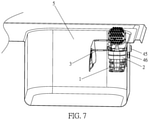
As shown in FIGS. 2 and 7 , in order to facilitate the installation of the draining rack body 1 and the sink, the fixing device 4 further includes a first magnetic attraction component 44 and a second magnetic attraction component 45. A limiting hole a is provided on the draining rack body 1, and the first magnetic attraction component 44 is inserted into the limiting hole a. The second magnetic attraction component 45 is arranged on the outer wall of the sink 5, and the second magnetic attraction component 45 is used in conjunction with the first magnetic attraction component 44 to fix the draining rack body 1. The draining rack body 1 is detachably connected to the sink 5 in a magnetic fixing manner, which is convenient for users to disassemble and assemble the draining rack body 1 according to requirements to adjust the use space of the sink 5.
Further, the first magnetic attraction component 44 includes: a fixing assembly 441, a first magnetic attraction part 442 and a flexible washer 443.
The fixing assembly 441 is inserted into the limiting hole a, the first magnetic attraction part 442 is adhered to the fixing assembly 441, and the flexible washer 443 is embedded between the first magnetic attraction part 442 and the fixing assembly 441 and partially protrudes from the fixing assembly 441 to avoid the first magnetic attraction part 442 scratching the sink 5 during use.
Further, the second magnetic attraction component 45 includes: a second magnetic attraction part 451 and an adhesive layer 452. One end of the adhesive layer 452 is adhered to the second magnetic attraction part 451, and the other end is adhered to the outer wall of the sink 5 corresponding to the second magnetic attraction part 451. Preferably, the adhesive layer 452 is a strong double-sided adhesive tape. The first magnetic attraction part 442 and the second magnetic attraction part 451 are both neodymium iron boron strong magnets.
As shown in FIG. 4 , the cleaning brush holder 2 includes a brush holder body 21 on which a disassembly structure is provided. The disassembly structure is used to embody the detachable assembly of the cleaning brush holder 2 and the draining rack body 1. Preferably, the brush holder body 21 is U-shaped, the shape of both ends of the draining rack body 1 is corresponding to the brush holder body 21, and the disassembly structure is symmetrically provided with the clamping slots e at both ends of the brush holder body 21, and the clamping slots e is set corresponding to the brush holder body 21 to be U-shaped. The brush holder body 21 can be assembled with both ends of the draining rack body 1 through the clamping slots e. In this way, it is convenient for users who use the left or right hand as the dominant hand.
Further, an inserting plate 22 is provided in the middle of the brush holder body 21, an insertion portion for inserting the cleaning brush is arranged on the inserting plate 22, and a plurality of elastic abutment blocks 23 are arranged on the edge portion of the insertion portion. The elastic abutment blocks 23 are compressed and deformed during the insertion and placement of the cleaning brush, and after the cleaning brush is inserted, the cleaning brush is pressed tightly to maintain in a fixed inserted state under the action of restoring force of the elastic abutment blocks. It should be noted that the insertion state is vertical to the placement surface. This structure can prevent the cleaning brush from colliding with the cleaning brush holder 2 when it is inserted to generate noise and the insertion portion is difficult to control, which affects the neatness of the placement and causes the inclined protrusion of the cleaning brush holder 2 to occupy the space of the sink 5.
Further, the plurality of elastic abutment blocks 23 are arranged equidistantly along a circumferential direction of the insertion portion, and an end of the elastic abutment block 23 away from the edge portion is oriented to the center of the insertion portion. Preferably, the elastic abutment block 23 is triangular, trapezoidal, elliptical, rhombic or rectangular. In this embodiment, the elastic abutment block 23 is triangular. A first draining sink b is symmetrically provided at one end of each elastic abutment block 23 near the edge portion, and a second draining sink c is symmetrically provided away from the edge portion. Preferably, the first draining sink b has a circular arc shape, and the second draining sink c has a triangular shape.
Further, a water collection tank d is provided on the inserting plate 22, and the insertion portion is set in the water collection tank d. The water collection tank d is used to collect the water on the cleaning brush and drain it down through the first draining sink b and the second draining sink c. The brush holder body 21 is made of silicone, rubber or plastic. In this embodiment, the brush holder body 21 is made of silica gel.
As shown in FIGS. 5 and 6 , the towel hanger 3 includes a hanger body 31, a rotating member 32 and a stopper 33.
The towel hanger 3 includes a hanger body 31, a rotating member 32 and a stopper 33. The hanger body 31 is rotatably assembled on the draining rack body 1 and can rotate relative to the draining rack body 1 to be folded on the draining rack body 1 or in use. The rotating member 32 is assembled between the hanger body 31 and the draining rack body 1. The stopper 33 is assembled between the hanger body 31 and the draining rack body 1, and is used to limit the rotation angle of the draining body 31 to maintain the hanger body 31 in usage state.
Further, the stopper 33 includes an eccentric ball. The eccentric ball is assembled on the hanger body 31 and located on a side of the rotating member 32 and configured to rotate with the hanger body 31 to be abutted against the draining rack body 1 to limit the assembly of the hanger body 31. The hanger body 31 is offset from a center of the eccentric ball. In other embodiments, the stopper 33 is a bent portion formed by bending the end of the connecting rod 312 away from the supporting rod 313, and the angle between the bent portion and the connecting rod 312 is 90 degrees.
Further, the rotating member 32 includes a rotating block. The rotating block is provided with two mounting holes for the rack rod of the hanger body 31 and the rotating part of the draining rack body 1 at intervals. Preferably, the rotating block is oval.
The hanger body 31 includes: a hanging rod 311, a connecting rod 312 and a supporting rod 313. The connecting rod 312 is assembled to the open end of the draining rack body 1 through the rotating member 32. The supporting rod 313 connects the hanging rod 311 and the connecting rod 312. Preferably, the hanging rod 311 may be provided with one or more. In this embodiment, one hanging rod 311 may be provided. There are two supporting rods 313 and connecting rods 312. One end of the two supporting rods 313 is respectively assembled on the two ends of the hanging rod 311, and the other end is respectively assembled on one end of the two connecting rods 312. The eccentric ball and the other end of the connecting rod 312 have an interference fit. The rotating member 32 is assembled on the connecting rod 312 close to the end of the stopper 33.
As shown in FIG. 6 , in order to avoid the problem of the draining rack body 1 causing damage to the inner wall of the sink during use, and the problem of the draining rack body 1 being close to the inner wall of the sink to result in dirt accumulating and difficulty in cleaning, a supporting frame 46 is provided on the draining rack body 1 on the side of the fixing device. The supporting frame 46 extends from the side of the draining rack body 1 to the side close to the sink, and forms an angle with the draining rack body 1. The distance between the supporting frame 46 and the draining rack body 1 is smaller than the thickness of the first magnetic attraction component 44 protruding from the draining rack body 1. A protective cover 47 is sheathed on the supporting frame 46 at one end away from the draining rack body 1. Preferably, the protective cover 47 is a sponge product.
The working principle of the present disclosure is roughly as follows. During use, according to the user's hand habits, the symmetrical clamping slots e on both ends of the brush holder body 21 are clamped with the rack bars of the draining rack body 1 to install the cleaning brush holder on the left or right side of the draining port of the draining rack body 1 to make it easier for users to access. When the brush holder does not need to be cleaned, it is disassembled to increase the use space of the draining rack body 1 to achieve the effect of flexible space adjustment.
In addition, the elastic abutment blocks 23 are arranged on the installation position 422, so that when the cleaning brush is inserted, the elastic abutment blocks 23 are compressed and deformed during the insertion and placement of the cleaning brush, and after the cleaning brush is inserted, the cleaning brush is pressed tightly to maintain in a perpendicular manner to the placement surface under the action of restoring force of the elastic abutment blocks 23, which improves the neatness of storage, and avoids the problem of oblique protrusions occupying the space of the sink when the cleaning brush is inserted obliquely, and the process of inserting and removing the cleaning brush is very quiet, docile and comfortable.
Finally, the towel hanger 3 is assembled on the draining rack body 1 through the rotating member 32, and when the towels do not need to be dried, the towel hanger 3 is rotated to fold on the draining rack body 1, thereby saving the space of the sink 5. Besides, the stopper 33 is an eccentric ball assembled on the towel hanger 3, and the eccentric ball can make the towel hanger 3 rotate relative to the draining rack body 1 and stop at a predetermined drying angle, thereby protecting the towel hanger 3 and the draining rack body 1 from being scratched.
The main difference between this embodiment and the first embodiment is that, as shown in FIGS. 7 and 8 , the fixing device 4 includes: a fixing plate 41, a clamping assembly 42 and a connecting piece 43. The clamping assembly 42 is fixedly assembled on the fixing plate 41 and used to clamp the draining rack body 1. One end of the connecting piece 43 is fixedly assembled on the fixing plate 41, and the other end is fixedly connected to the wall surface. Preferably, the connecting piece 43 is a double-sided tape. When the draining rack body 1 is installed, it is suitable for both the sink 5 with a thinner wall or a bathroom with thicker wall, which reduces the environment conditions for the installation of the draining rack and increases its application place.
Furthermore, the clamping assembly 42 includes a bracket block 421, a mounting position 422 and a buckle block 423.
The bracket block 421 is fixedly assembled on the fixing plate 41 and used to support the steel bar of the draining rack body 1 when in use. Preferably, the bracket block 42 is L-shaped, the vertical end of the bracket block 421 is parallel to the fixing plate 41, and the horizontal end of the bracket block 421 is fixedly connected to the fixing plate 41 on the side away from the vertical end. The fixing plate 41 is provided with a square boss, and the mounting position 422 is fixedly assembled on the boss. The installation includes two convex blocks arranged on the boss at intervals, and two opposite sides of the two convex blocks are provided with holes. The rotating shaft is inserted into the two holes. The buckle block 423 is hinged to the mounting position 422 via a rotating shaft. The buckle block 423 is used to rotate relative to the fixing plate 41 to buckle or unbuckle with the bracket block 421 to clamp or loosen the steel bar. Preferably, the buckle hole of the buckle block 423 is provided corresponding to the clamping block. When the buckle block 423 and the bracket block 421 are buckled together, the bracket block 421 is accommodated in the buckle hole and cooperates with the buckle block 423 to clamp the steel bar.
The above are only used to illustrate the technical solution of the present disclosure and not to limit it. Other modifications or equivalent substitutions made by those of ordinary skill in the art to the technical solution of the present disclosure shall be covered within the scope of the claims of the present invention as long as they do not depart from the spirit and scope of the technical solution of the present disclosure.
Claims (8)
1. A multifunctional draining rack, comprising:
a draining rack body (1) provided with a storage space;
a cleaning brush holder (2) detachably assembled on the draining rack body (1); and
a towel hanger (3) assembled on the draining rack body and configured to rotate relative to the draining rack body (1) for folding or in use,
wherein the towel hanger (3) comprises:
a hanger body (31) rotatably assembled on the draining rack body (1) and configured to rotate relative to the draining rack body (1) to be folded on the draining rack body (1) or in use;
a rotating member (32) assembled between the hanger body (31) and the draining rack body (1); and
a stopper (33) assembled between the hanger body (31) and the draining rack body (1) for limiting a rotation angle of the hanger body (31) to maintain the hanger body (31) in usage state, and
wherein the stopper (33) comprises: an eccentric ball assembled on the hanger body (31), located on a side of the rotating member (32) and configured to rotate with the hanger body (31) to be abutted against the draining rack body (1), and the hanger body (31) is offset from a center of the eccentric ball.
2. The multifunctional draining rack according to claim 1 , wherein the cleaning brush holder (2) comprises: a brush holder body (21) on which an insertion portion for inserting a cleaning brush is provided; a plurality of elastic abutment blocks (23) are provided on an edge portion of the insertion portion, and the elastic abutment blocks (23) are compressed and deformed during the insertion and placement of the cleaning brush, and after the cleaning brush is inserted, the cleaning brush is pressed tightly to maintain in a fixed inserted state under the action of restoring force of the elastic abutment blocks (23), and
wherein clamping slots (e) are symmetrically provided at both ends of the insertion portion on the brush holder body (21), and a rack bar of the draining rack body (1) is clamped in the clamping slots (e) to embody that the cleaning brush holder (2) and the draining rack body (1) are detachably assembled.
3. The multifunctional draining rack according to claim 2 , wherein a plurality of the elastic abutment blocks (23) are arranged equidistantly along a circumferential direction of the insertion portion, and one end of the elastic abutment blocks (23) away from the edge portion is oriented to a center of the insertion portion.
4. The multifunctional draining rack according to claim 1 , wherein the rotating member (32) comprises: a rotating block on which two mounting holes are assembled at intervals, and the mounting holes are respectively configured to assemble the hanger body (31) and the draining rack body (1).
5. The multifunctional draining rack according to claim 1 , further comprising: a fixing device (4) detachably assembled on the draining rack body (1) and configured to fix and mount the draining rack body (1) on a wall surface.
6. The multifunctional draining rack according to claim 5 , wherein the fixing device (4) comprises:
a fixing plate (41);
a clamping assembly (42) fixedly assembled on the fixing plate (41) for clamping the draining rack body (1); and
a connecting piece (43) of which one end is fixedly assembled on the fixing plate (41), and the other end is fixedly connected to the wall surface.
7. The multifunctional draining rack according to claim 6 , wherein the clamping assembly (42) comprises:
a bracket block (421) fixedly assembled on the fixing plate (41) and configured to support a rack bar of the draining rack body (1);
a mounting position (422) provided on the fixing plate (41); and
a buckle block (423) hinged on the mounting position (422) by a rotating shaft and configured to rotate relative to the fixing plate (41) to buckle or unbuckle with the bracket block (421) to clamp or loosen the rack bar of the draining rack body (1).
8. The multifunctional draining rack according to claim 5 , wherein a limiting hole (a) is provided on the draining rack body (1), and the fixing device (4) further comprises:
a first magnetic attraction component (44) inserted into the limiting hole (a); and
a second magnetic attraction component (45) arranged on the wall surface and configured in conjunction with the first magnetic attraction component (44) to fix the draining rack body (1) to a sink (5).
Priority Applications (1)
| Application Number | Priority Date | Filing Date | Title |
|---|---|---|---|
| US17/032,697 US11224290B1 (en) | 2020-09-25 | 2020-09-25 | Multifunctional draining rack |
Applications Claiming Priority (1)
| Application Number | Priority Date | Filing Date | Title |
|---|---|---|---|
| US17/032,697 US11224290B1 (en) | 2020-09-25 | 2020-09-25 | Multifunctional draining rack |
Publications (1)
| Publication Number | Publication Date |
|---|---|
| US11224290B1 true US11224290B1 (en) | 2022-01-18 |
Family
ID=79293739
Family Applications (1)
| Application Number | Title | Priority Date | Filing Date |
|---|---|---|---|
| US17/032,697 Active US11224290B1 (en) | 2020-09-25 | 2020-09-25 | Multifunctional draining rack |
Country Status (1)
| Country | Link |
|---|---|
| US (1) | US11224290B1 (en) |
Cited By (2)
| Publication number | Priority date | Publication date | Assignee | Title |
|---|---|---|---|---|
| USD953120S1 (en) * | 2020-12-04 | 2022-05-31 | Jun Zhang | Kitchen utility rack |
| US20220240726A1 (en) * | 2019-01-03 | 2022-08-04 | Tinkered Inc. | Cleaning Apparatus Holder |
Citations (19)
| Publication number | Priority date | Publication date | Assignee | Title |
|---|---|---|---|---|
| US1476034A (en) * | 1921-02-12 | 1923-12-04 | Alfonso A Banks | Towel rack |
| US2042517A (en) * | 1934-01-15 | 1936-06-02 | Kelvinator Corp | Refrigerating apparatus |
| US2214869A (en) * | 1938-12-09 | 1940-09-17 | West Marguerite | Kitchen appliance |
| US3023991A (en) * | 1959-01-29 | 1962-03-06 | Fisher Janina | Magnetic hanger |
| US4334621A (en) * | 1978-11-01 | 1982-06-15 | Weber Girard M | Holder |
| US4345688A (en) * | 1980-07-18 | 1982-08-24 | Albert De Boer | Tool holder device |
| US4905951A (en) * | 1988-02-26 | 1990-03-06 | Putness Carl M | Quick insert and quick release tool holder |
| USD475561S1 (en) * | 2002-10-16 | 2003-06-10 | Zenith Products Corp. | Corner caddy |
| US20070131629A1 (en) * | 2005-12-13 | 2007-06-14 | Helen Of Troy Limited | Drying storage rack |
| US7353970B1 (en) * | 2004-10-13 | 2008-04-08 | Harrison-Coats Daneen Y | Food and beverage article dispenser |
| US20100288659A1 (en) * | 2009-05-18 | 2010-11-18 | Kayla Dang | Universal toothbrush holder |
| US8296876B2 (en) * | 2008-12-02 | 2012-10-30 | Simplehuman Llc | Sink organizer |
| US8522998B2 (en) * | 2007-05-04 | 2013-09-03 | Electrolux Home Products, Inc. | Dishwasher basket assembly |
| US8763818B1 (en) * | 2013-03-08 | 2014-07-01 | Richard Pargansky | Kitchen sink organizer |
| US8973763B2 (en) * | 2013-03-08 | 2015-03-10 | Richard Pargansky | Dish drying rack and tray assembly |
| US20150230667A1 (en) * | 2014-02-20 | 2015-08-20 | Elkay Manufacturing Company | Magnetic sink accessory system |
| US9462930B2 (en) * | 2008-05-02 | 2016-10-11 | Arcelik Anonim Sirketi | Dishwasher with a device for assembling the basket to the extracting rail |
| US9848723B1 (en) * | 2016-12-22 | 2017-12-26 | Actman Corp. | Reversible makeup brush holder |
| US9883742B2 (en) * | 2014-03-14 | 2018-02-06 | Simplehuman, Llc | Shower caddy with shelf adjustably maounted along an elongate support member |
-
2020
- 2020-09-25 US US17/032,697 patent/US11224290B1/en active Active
Patent Citations (19)
| Publication number | Priority date | Publication date | Assignee | Title |
|---|---|---|---|---|
| US1476034A (en) * | 1921-02-12 | 1923-12-04 | Alfonso A Banks | Towel rack |
| US2042517A (en) * | 1934-01-15 | 1936-06-02 | Kelvinator Corp | Refrigerating apparatus |
| US2214869A (en) * | 1938-12-09 | 1940-09-17 | West Marguerite | Kitchen appliance |
| US3023991A (en) * | 1959-01-29 | 1962-03-06 | Fisher Janina | Magnetic hanger |
| US4334621A (en) * | 1978-11-01 | 1982-06-15 | Weber Girard M | Holder |
| US4345688A (en) * | 1980-07-18 | 1982-08-24 | Albert De Boer | Tool holder device |
| US4905951A (en) * | 1988-02-26 | 1990-03-06 | Putness Carl M | Quick insert and quick release tool holder |
| USD475561S1 (en) * | 2002-10-16 | 2003-06-10 | Zenith Products Corp. | Corner caddy |
| US7353970B1 (en) * | 2004-10-13 | 2008-04-08 | Harrison-Coats Daneen Y | Food and beverage article dispenser |
| US20070131629A1 (en) * | 2005-12-13 | 2007-06-14 | Helen Of Troy Limited | Drying storage rack |
| US8522998B2 (en) * | 2007-05-04 | 2013-09-03 | Electrolux Home Products, Inc. | Dishwasher basket assembly |
| US9462930B2 (en) * | 2008-05-02 | 2016-10-11 | Arcelik Anonim Sirketi | Dishwasher with a device for assembling the basket to the extracting rail |
| US8296876B2 (en) * | 2008-12-02 | 2012-10-30 | Simplehuman Llc | Sink organizer |
| US20100288659A1 (en) * | 2009-05-18 | 2010-11-18 | Kayla Dang | Universal toothbrush holder |
| US8763818B1 (en) * | 2013-03-08 | 2014-07-01 | Richard Pargansky | Kitchen sink organizer |
| US8973763B2 (en) * | 2013-03-08 | 2015-03-10 | Richard Pargansky | Dish drying rack and tray assembly |
| US20150230667A1 (en) * | 2014-02-20 | 2015-08-20 | Elkay Manufacturing Company | Magnetic sink accessory system |
| US9883742B2 (en) * | 2014-03-14 | 2018-02-06 | Simplehuman, Llc | Shower caddy with shelf adjustably maounted along an elongate support member |
| US9848723B1 (en) * | 2016-12-22 | 2017-12-26 | Actman Corp. | Reversible makeup brush holder |
Cited By (3)
| Publication number | Priority date | Publication date | Assignee | Title |
|---|---|---|---|---|
| US20220240726A1 (en) * | 2019-01-03 | 2022-08-04 | Tinkered Inc. | Cleaning Apparatus Holder |
| US11800955B2 (en) * | 2019-01-03 | 2023-10-31 | Tinkered Inc. | Cleaning apparatus holder |
| USD953120S1 (en) * | 2020-12-04 | 2022-05-31 | Jun Zhang | Kitchen utility rack |
Similar Documents
| Publication | Publication Date | Title |
|---|---|---|
| US11224290B1 (en) | Multifunctional draining rack | |
| CA2662783C (en) | Wall mountable wire grid organizer system with removable accessories | |
| US8707475B2 (en) | Shower door storage assembly | |
| WO2009097298A1 (en) | Shelving system | |
| US8726445B1 (en) | Shower-mounted back scrubber | |
| US6343774B1 (en) | Body washer device | |
| WO2022061711A1 (en) | Multifunctional drain rack | |
| CN214231138U (en) | Foldable towel hanging rack | |
| US20070125723A1 (en) | Movable bath mat bar for towel bar or bracket mount | |
| US9301655B1 (en) | Hands free washing assembly | |
| CN213216419U (en) | Cleaning brush holder | |
| KR20170004230U (en) | Folding shampoo basin for use of the space | |
| KR20080000052U (en) | versatile hanger which is linked by faucet | |
| KR20190001898U (en) | Multi-bathroom toilet partition | |
| KR100497641B1 (en) | Plinth for kitchen furniture | |
| CN213345454U (en) | Novel foldable cloth wiping frame and towel rack | |
| US20080290055A1 (en) | Shower caddy | |
| CN210582328U (en) | Paper towel holder | |
| CN215424299U (en) | A kind of bathtub | |
| CN219249997U (en) | Water tap rack | |
| CN210276979U (en) | Household washbasin convenient for placing daily necessities | |
| JP2002315681A (en) | Magnetic-force type compact kitchen-knife receiver | |
| KR200304951Y1 (en) | Plinth for kitchen furniture | |
| CN218528560U (en) | Tap storage draining rack | |
| CN216060294U (en) | Novel simple toothbrush holder |
Legal Events
| Date | Code | Title | Description |
|---|---|---|---|
| FEPP | Fee payment procedure |
Free format text: ENTITY STATUS SET TO UNDISCOUNTED (ORIGINAL EVENT CODE: BIG.); ENTITY STATUS OF PATENT OWNER: MICROENTITY |
|
| FEPP | Fee payment procedure |
Free format text: ENTITY STATUS SET TO SMALL (ORIGINAL EVENT CODE: SMAL); ENTITY STATUS OF PATENT OWNER: MICROENTITY Free format text: ENTITY STATUS SET TO MICRO (ORIGINAL EVENT CODE: MICR); ENTITY STATUS OF PATENT OWNER: MICROENTITY |