US11223844B2 - Image encoder, image decoder, image encoding method, and image decoding method - Google Patents
Image encoder, image decoder, image encoding method, and image decoding method Download PDFInfo
- Publication number
- US11223844B2 US11223844B2 US16/572,323 US201916572323A US11223844B2 US 11223844 B2 US11223844 B2 US 11223844B2 US 201916572323 A US201916572323 A US 201916572323A US 11223844 B2 US11223844 B2 US 11223844B2
- Authority
- US
- United States
- Prior art keywords
- partition
- block
- prediction
- motion vector
- image
- Prior art date
- Legal status (The legal status is an assumption and is not a legal conclusion. Google has not performed a legal analysis and makes no representation as to the accuracy of the status listed.)
- Active, expires
Links
- 238000000034 method Methods 0.000 title claims description 318
- 238000005192 partition Methods 0.000 claims abstract description 682
- 230000033001 locomotion Effects 0.000 claims abstract description 547
- 239000013598 vector Substances 0.000 claims abstract description 454
- 230000008569 process Effects 0.000 claims description 203
- 238000009499 grossing Methods 0.000 abstract description 50
- PXFBZOLANLWPMH-UHFFFAOYSA-N 16-Epiaffinine Natural products C1C(C2=CC=CC=C2N2)=C2C(=O)CC2C(=CC)CN(C)C1C2CO PXFBZOLANLWPMH-UHFFFAOYSA-N 0.000 description 71
- 238000010586 diagram Methods 0.000 description 63
- 238000012545 processing Methods 0.000 description 56
- 238000012937 correction Methods 0.000 description 32
- 238000013139 quantization Methods 0.000 description 31
- 241000023320 Luma <angiosperm> Species 0.000 description 30
- OSWPMRLSEDHDFF-UHFFFAOYSA-N methyl salicylate Chemical group COC(=O)C1=CC=CC=C1O OSWPMRLSEDHDFF-UHFFFAOYSA-N 0.000 description 30
- 238000009795 derivation Methods 0.000 description 29
- 230000006870 function Effects 0.000 description 23
- 239000000470 constituent Substances 0.000 description 19
- 238000001914 filtration Methods 0.000 description 18
- 238000011156 evaluation Methods 0.000 description 17
- 230000014509 gene expression Effects 0.000 description 13
- 239000011159 matrix material Substances 0.000 description 13
- 230000005236 sound signal Effects 0.000 description 12
- 230000011664 signaling Effects 0.000 description 9
- 230000000694 effects Effects 0.000 description 7
- 230000003044 adaptive effect Effects 0.000 description 6
- 230000008901 benefit Effects 0.000 description 6
- 230000008859 change Effects 0.000 description 6
- 238000004891 communication Methods 0.000 description 6
- 230000003287 optical effect Effects 0.000 description 6
- 101100537098 Mus musculus Alyref gene Proteins 0.000 description 5
- 101150095908 apex1 gene Proteins 0.000 description 5
- 230000002146 bilateral effect Effects 0.000 description 5
- 230000006835 compression Effects 0.000 description 5
- 238000007906 compression Methods 0.000 description 5
- 238000003702 image correction Methods 0.000 description 5
- 230000005540 biological transmission Effects 0.000 description 4
- 238000006243 chemical reaction Methods 0.000 description 4
- 239000000284 extract Substances 0.000 description 4
- 238000005457 optimization Methods 0.000 description 4
- 230000001360 synchronised effect Effects 0.000 description 4
- 230000002123 temporal effect Effects 0.000 description 4
- 238000004458 analytical method Methods 0.000 description 3
- 229910003460 diamond Inorganic materials 0.000 description 3
- 239000010432 diamond Substances 0.000 description 3
- 210000000887 face Anatomy 0.000 description 3
- 230000006872 improvement Effects 0.000 description 3
- 238000003491 array Methods 0.000 description 2
- 230000001419 dependent effect Effects 0.000 description 2
- 238000005516 engineering process Methods 0.000 description 2
- 238000000605 extraction Methods 0.000 description 2
- 238000005286 illumination Methods 0.000 description 2
- 238000003384 imaging method Methods 0.000 description 2
- 230000010365 information processing Effects 0.000 description 2
- 238000002156 mixing Methods 0.000 description 2
- 230000004044 response Effects 0.000 description 2
- 238000000638 solvent extraction Methods 0.000 description 2
- 238000001228 spectrum Methods 0.000 description 2
- 238000006467 substitution reaction Methods 0.000 description 2
- 230000001131 transforming effect Effects 0.000 description 2
- 101000713575 Homo sapiens Tubulin beta-3 chain Proteins 0.000 description 1
- 101000713585 Homo sapiens Tubulin beta-4A chain Proteins 0.000 description 1
- 102100036790 Tubulin beta-3 chain Human genes 0.000 description 1
- 102100036788 Tubulin beta-4A chain Human genes 0.000 description 1
- 230000001174 ascending effect Effects 0.000 description 1
- 230000003190 augmentative effect Effects 0.000 description 1
- 230000001413 cellular effect Effects 0.000 description 1
- 239000002131 composite material Substances 0.000 description 1
- 238000004590 computer program Methods 0.000 description 1
- 238000010276 construction Methods 0.000 description 1
- 238000013500 data storage Methods 0.000 description 1
- 238000012217 deletion Methods 0.000 description 1
- 230000037430 deletion Effects 0.000 description 1
- 238000001514 detection method Methods 0.000 description 1
- 239000000446 fuel Substances 0.000 description 1
- 210000003128 head Anatomy 0.000 description 1
- 230000010354 integration Effects 0.000 description 1
- 238000010801 machine learning Methods 0.000 description 1
- 238000007726 management method Methods 0.000 description 1
- 239000000463 material Substances 0.000 description 1
- 239000000203 mixture Substances 0.000 description 1
- 238000010295 mobile communication Methods 0.000 description 1
- 238000012986 modification Methods 0.000 description 1
- 230000004048 modification Effects 0.000 description 1
- 238000012805 post-processing Methods 0.000 description 1
- 238000007781 pre-processing Methods 0.000 description 1
- 239000004065 semiconductor Substances 0.000 description 1
- 239000007787 solid Substances 0.000 description 1
- 230000000153 supplemental effect Effects 0.000 description 1
- 230000009466 transformation Effects 0.000 description 1
Images


Classifications
-
- H—ELECTRICITY
- H04—ELECTRIC COMMUNICATION TECHNIQUE
- H04N—PICTORIAL COMMUNICATION, e.g. TELEVISION
- H04N19/00—Methods or arrangements for coding, decoding, compressing or decompressing digital video signals
- H04N19/10—Methods or arrangements for coding, decoding, compressing or decompressing digital video signals using adaptive coding
- H04N19/134—Methods or arrangements for coding, decoding, compressing or decompressing digital video signals using adaptive coding characterised by the element, parameter or criterion affecting or controlling the adaptive coding
- H04N19/157—Assigned coding mode, i.e. the coding mode being predefined or preselected to be further used for selection of another element or parameter
-
- H—ELECTRICITY
- H04—ELECTRIC COMMUNICATION TECHNIQUE
- H04N—PICTORIAL COMMUNICATION, e.g. TELEVISION
- H04N19/00—Methods or arrangements for coding, decoding, compressing or decompressing digital video signals
- H04N19/10—Methods or arrangements for coding, decoding, compressing or decompressing digital video signals using adaptive coding
- H04N19/102—Methods or arrangements for coding, decoding, compressing or decompressing digital video signals using adaptive coding characterised by the element, parameter or selection affected or controlled by the adaptive coding
- H04N19/117—Filters, e.g. for pre-processing or post-processing
-
- H—ELECTRICITY
- H04—ELECTRIC COMMUNICATION TECHNIQUE
- H04N—PICTORIAL COMMUNICATION, e.g. TELEVISION
- H04N19/00—Methods or arrangements for coding, decoding, compressing or decompressing digital video signals
- H04N19/10—Methods or arrangements for coding, decoding, compressing or decompressing digital video signals using adaptive coding
- H04N19/102—Methods or arrangements for coding, decoding, compressing or decompressing digital video signals using adaptive coding characterised by the element, parameter or selection affected or controlled by the adaptive coding
- H04N19/103—Selection of coding mode or of prediction mode
- H04N19/105—Selection of the reference unit for prediction within a chosen coding or prediction mode, e.g. adaptive choice of position and number of pixels used for prediction
-
- H—ELECTRICITY
- H04—ELECTRIC COMMUNICATION TECHNIQUE
- H04N—PICTORIAL COMMUNICATION, e.g. TELEVISION
- H04N19/00—Methods or arrangements for coding, decoding, compressing or decompressing digital video signals
- H04N19/10—Methods or arrangements for coding, decoding, compressing or decompressing digital video signals using adaptive coding
- H04N19/102—Methods or arrangements for coding, decoding, compressing or decompressing digital video signals using adaptive coding characterised by the element, parameter or selection affected or controlled by the adaptive coding
- H04N19/119—Adaptive subdivision aspects, e.g. subdivision of a picture into rectangular or non-rectangular coding blocks
-
- H—ELECTRICITY
- H04—ELECTRIC COMMUNICATION TECHNIQUE
- H04N—PICTORIAL COMMUNICATION, e.g. TELEVISION
- H04N19/00—Methods or arrangements for coding, decoding, compressing or decompressing digital video signals
- H04N19/10—Methods or arrangements for coding, decoding, compressing or decompressing digital video signals using adaptive coding
- H04N19/169—Methods or arrangements for coding, decoding, compressing or decompressing digital video signals using adaptive coding characterised by the coding unit, i.e. the structural portion or semantic portion of the video signal being the object or the subject of the adaptive coding
- H04N19/17—Methods or arrangements for coding, decoding, compressing or decompressing digital video signals using adaptive coding characterised by the coding unit, i.e. the structural portion or semantic portion of the video signal being the object or the subject of the adaptive coding the unit being an image region, e.g. an object
- H04N19/176—Methods or arrangements for coding, decoding, compressing or decompressing digital video signals using adaptive coding characterised by the coding unit, i.e. the structural portion or semantic portion of the video signal being the object or the subject of the adaptive coding the unit being an image region, e.g. an object the region being a block, e.g. a macroblock
-
- H—ELECTRICITY
- H04—ELECTRIC COMMUNICATION TECHNIQUE
- H04N—PICTORIAL COMMUNICATION, e.g. TELEVISION
- H04N19/00—Methods or arrangements for coding, decoding, compressing or decompressing digital video signals
- H04N19/10—Methods or arrangements for coding, decoding, compressing or decompressing digital video signals using adaptive coding
- H04N19/169—Methods or arrangements for coding, decoding, compressing or decompressing digital video signals using adaptive coding characterised by the coding unit, i.e. the structural portion or semantic portion of the video signal being the object or the subject of the adaptive coding
- H04N19/182—Methods or arrangements for coding, decoding, compressing or decompressing digital video signals using adaptive coding characterised by the coding unit, i.e. the structural portion or semantic portion of the video signal being the object or the subject of the adaptive coding the unit being a pixel
-
- H—ELECTRICITY
- H04—ELECTRIC COMMUNICATION TECHNIQUE
- H04N—PICTORIAL COMMUNICATION, e.g. TELEVISION
- H04N19/00—Methods or arrangements for coding, decoding, compressing or decompressing digital video signals
- H04N19/50—Methods or arrangements for coding, decoding, compressing or decompressing digital video signals using predictive coding
- H04N19/503—Methods or arrangements for coding, decoding, compressing or decompressing digital video signals using predictive coding involving temporal prediction
- H04N19/51—Motion estimation or motion compensation
- H04N19/537—Motion estimation other than block-based
-
- H—ELECTRICITY
- H04—ELECTRIC COMMUNICATION TECHNIQUE
- H04N—PICTORIAL COMMUNICATION, e.g. TELEVISION
- H04N19/00—Methods or arrangements for coding, decoding, compressing or decompressing digital video signals
- H04N19/50—Methods or arrangements for coding, decoding, compressing or decompressing digital video signals using predictive coding
- H04N19/503—Methods or arrangements for coding, decoding, compressing or decompressing digital video signals using predictive coding involving temporal prediction
- H04N19/51—Motion estimation or motion compensation
- H04N19/56—Motion estimation with initialisation of the vector search, e.g. estimating a good candidate to initiate a search
-
- H—ELECTRICITY
- H04—ELECTRIC COMMUNICATION TECHNIQUE
- H04N—PICTORIAL COMMUNICATION, e.g. TELEVISION
- H04N19/00—Methods or arrangements for coding, decoding, compressing or decompressing digital video signals
- H04N19/50—Methods or arrangements for coding, decoding, compressing or decompressing digital video signals using predictive coding
- H04N19/587—Methods or arrangements for coding, decoding, compressing or decompressing digital video signals using predictive coding involving temporal sub-sampling or interpolation, e.g. decimation or subsequent interpolation of pictures in a video sequence
-
- H—ELECTRICITY
- H04—ELECTRIC COMMUNICATION TECHNIQUE
- H04N—PICTORIAL COMMUNICATION, e.g. TELEVISION
- H04N19/00—Methods or arrangements for coding, decoding, compressing or decompressing digital video signals
- H04N19/85—Methods or arrangements for coding, decoding, compressing or decompressing digital video signals using pre-processing or post-processing specially adapted for video compression
- H04N19/86—Methods or arrangements for coding, decoding, compressing or decompressing digital video signals using pre-processing or post-processing specially adapted for video compression involving reduction of coding artifacts, e.g. of blockiness
-
- H—ELECTRICITY
- H04—ELECTRIC COMMUNICATION TECHNIQUE
- H04N—PICTORIAL COMMUNICATION, e.g. TELEVISION
- H04N19/00—Methods or arrangements for coding, decoding, compressing or decompressing digital video signals
- H04N19/90—Methods or arrangements for coding, decoding, compressing or decompressing digital video signals using coding techniques not provided for in groups H04N19/10-H04N19/85, e.g. fractals
- H04N19/96—Tree coding, e.g. quad-tree coding
Definitions
- This disclosure relates to video coding, and particularly to video encoding and decoding systems, components, and methods for performing an inter prediction function to build a current block based on a reference frame or an intra prediction function to build a current block based on an encoded/decoded reference block in a current frame.
- This disclosure relates to further advancements, improvements and optimizations in video coding, particularly, in connection with an inter prediction function or an intra prediction function, splitting an image block into a plurality of partitions including at least a first partition having a non-rectangular shape (e.g., a triangle) and a second partition.
- a first partition having a non-rectangular shape e.g., a triangle
- an image decoder which includes circuitry, and a memory coupled to the circuitry.
- the circuitry in operation, performs a boundary smoothing operation along a boundary between a first partition having a triangular shape and a second partition having a triangular shape that are split from an image block.
- the boundary smoothing operation includes: first-deriving a first motion vector for the first partition from a first set of motion vector candidates; second-deriving a second motion vector for the second partition from a second set of motion vector candidates; first-predicting first values of a set of pixels of the first partition along the boundary, using the first motion vector; second-predicting second values of the set of pixels of the first partition along the boundary, using the second motion vector; weighting the first values and the second values; and decoding the first partition using the weighted first values and the weighted second values.
- an image decoder which includes: an entropy decoder which, in operation, receives and decodes an encoded bitstream to obtain quantized transform coefficients; an inverse quantizer and transformer which, in operation, inverse quantizes the quantized transform coefficients to obtain transform coefficients and inverse transform the transform coefficients to obtain residuals; an adder which, in operation, adds the residuals outputted from the inverse quantizer and transformer and predictions outputted from a prediction controller to reconstruct blocks; and the prediction controller coupled to an inter predictor, an intra predictor, and a memory, wherein the inter predictor, in operation, generates a prediction of a current block based on a reference block in a decoded reference picture and the intra predictor, in operation, generates a prediction of a current block based on an decoded reference block in a current picture.
- the image decoder in operation, performs a boundary smoothing operation along a boundary between a first partition having a triangular shape and a second partition having a triangular shape that are split from an image block.
- the boundary smoothing operation includes: first-deriving a first motion vector for the first partition from a first set of motion vector candidates; second-deriving a second motion vector for the second partition from a second set of motion vector candidates; first-predicting first values of a set of pixels of the first partition along the boundary, using the first motion vector; second-predicting second values of the set of pixels of the first partition along the boundary, using the second motion vector; weighting the first values and the second values; and decoding the first partition using the weighted first values and the weighted second values.
- an image decoding method for performing a boundary smoothing operation along a boundary between a first partition having a triangular shape and a second partition having a triangular shape that are split from an image block.
- the method includes generally six steps: first-deriving a first motion vector for the first partition from a first set of motion vector candidates; second-deriving a second motion vector for the second partition from a second set of motion vector candidates; first-predicting first values of a set of pixels of the first partition along the boundary, using the first motion vector; second-predicting second values of the set of pixels of the first partition along the boundary, using the second motion vector; weighting the first values and the second values; and decoding the first partition using the weighted first values and the weighted second values.
- an image encoder including circuitry and a memory coupled to the circuitry.
- the circuitry in operation, performs: splitting an image block into a plurality of partitions including a first partition having a non-rectangular shape and a second partition; predicting a first motion vector for the first partition and a second motion vector for the second partition; and encoding the first partition using the first motion vector and the second partition using the second motion vector.
- Some implementations of embodiments of the present disclosure may improve an encoding efficiency, may simply be an encoding/decoding process, may accelerate an encoding/decoding process speed, may efficiently select appropriate components/operations used in encoding and decoding such as appropriate filter, block size, motion vector, reference picture, reference block, etc.
- FIG. 1 is a block diagram illustrating a functional configuration of an encoder according to an embodiment.
- FIG. 2 is a flow chart indicating one example of an overall encoding process performed by the encoder.
- FIG. 3 is a conceptual diagram illustrating one example of block splitting.
- FIG. 4A is a conceptual diagram illustrating one example of a slice configuration.
- FIG. 4B is a conceptual diagram illustrating one example of a tile configuration.
- FIG. 5A is a chart indicating transform basis functions for various transform types.
- FIG. 5B is a conceptual diagram illustrating example spatially varying transforms (SVT).
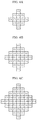
- FIG. 6A is a conceptual diagram illustrating one example of a filter shape used in an adaptive loop filter (ALF).
- ALF adaptive loop filter
- FIG. 6B is a conceptual diagram illustrating another example of a filter shape used in an ALF.
- FIG. 6C is a conceptual diagram illustrating another example of a filter shape used in an ALF.
- FIG. 7 is a block diagram indicating one example of a specific configuration of a loop filter which functions as a deblocking filter (DBF).
- DPF deblocking filter
- FIG. 8 is a conceptual diagram indicating an example of a deblocking filter having a symmetrical filtering characteristic with respect to a block boundary.
- FIG. 9 is a conceptual diagram for illustrating a block boundary on which a deblocking filter process is performed.
- FIG. 10 is a conceptual diagram indicating examples of Bs values.
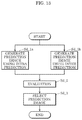
- FIG. 11 is a flow chart illustrating one example of a process performed by a prediction processor of the encoder.
- FIG. 12 is a flow chart illustrating another example of a process performed by the prediction processor of the encoder.
- FIG. 13 is a flow chart illustrating another example of a process performed by the prediction processor of the encoder.
- FIG. 14 is a conceptual diagram illustrating sixty-seven intra prediction modes used in intra prediction in an embodiment.
- FIG. 15 is a flow chart illustrating an example basic processing flow of inter prediction.
- FIG. 16 is a flow chart illustrating one example of derivation of motion vectors.
- FIG. 17 is a flow chart illustrating another example of derivation of motion vectors.
- FIG. 18 is a flow chart illustrating another example of derivation of motion vectors.
- FIG. 19 is a flow chart illustrating an example of inter prediction in normal inter mode.
- FIG. 20 is a flow chart illustrating an example of inter prediction in merge mode.
- FIG. 21 is a conceptual diagram for illustrating one example of a motion vector derivation process in merge mode.
- FIG. 22 is a flow chart illustrating one example of frame rate up conversion (FRUC) process.
- FRUC frame rate up conversion
- FIG. 23 is a conceptual diagram for illustrating one example of pattern matching (bilateral matching) between two blocks along a motion trajectory.
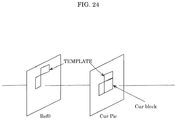
- FIG. 24 is a conceptual diagram for illustrating one example of pattern matching (template matching) between a template in a current picture and a block in a reference picture.
- FIG. 25A is a conceptual diagram for illustrating one example of deriving a motion vector of each sub-block based on motion vectors of a plurality of neighboring blocks.
- FIG. 25B is a conceptual diagram for illustrating one example of deriving a motion vector of each sub-block in affine mode in which three control points are used.
- FIG. 26A is a conceptual diagram for illustrating an affine merge mode.
- FIG. 26B is a conceptual diagram for illustrating an affine merge mode in which two control points are used.
- FIG. 26C is a conceptual diagram for illustrating an affine merge mode in which three control points are used.
- FIG. 27 is a flow chart illustrating one example of a process in affine merge mode.
- FIG. 28A is a conceptual diagram for illustrating an affine inter mode in which two control points are used.
- FIG. 28B is a conceptual diagram for illustrating an affine inter mode in which three control points are used.
- FIG. 29 is a flow chart illustrating one example of a process in affine inter mode.
- FIG. 30A is a conceptual diagram for illustrating an affine inter mode in which a current block has three control points and a neighboring block has two control points.
- FIG. 30B is a conceptual diagram for illustrating an affine inter mode in which a current block has two control points and a neighboring block has three control points.
- FIG. 31A is a flow chart illustrating a merge mode process including decoder motion vector refinement (DMVR).
- DMVR decoder motion vector refinement
- FIG. 31B is a conceptual diagram for illustrating one example of a DMVR process.
- FIG. 32 is a flow chart illustrating one example of generation of a prediction image.
- FIG. 33 is a flow chart illustrating another example of generation of a prediction image.
- FIG. 34 is a flow chart illustrating another example of generation of a prediction image.
- FIG. 35 is a flow chart illustrating one example of a prediction image correction process performed by an overlapped block motion compensation (OBMC) process.
- OBMC overlapped block motion compensation
- FIG. 36 is a conceptual diagram for illustrating one example of a prediction image correction process performed by an OBMC process.
- FIG. 37 is a conceptual diagram for illustrating generation of two triangular prediction images.
- FIG. 38 is conceptual diagram for illustrating a model assuming uniform linear motion.
- FIG. 39 is a conceptual diagram for illustrating one example of a prediction image generation method using a luminance correction process performed by a local illumination compensation (LIC) process.
- LIC local illumination compensation
- FIG. 40 is a block diagram illustrating a mounting example of the encoder.
- FIG. 41 is a block diagram illustrating a functional configuration of a decoder according to an embodiment.
- FIG. 42 is a flow chart illustrating one example of an overall decoding process performed by the decoder.
- FIG. 43 is a flow chart illustrating one example of a process performed by a prediction processor of the decoder.
- FIG. 44 is a flow chart illustrating another example of a process performed by the prediction processor of the decoder.
- FIG. 45 is a flow chart illustrating an example of inter prediction in normal inter mode in the decoder.
- FIG. 46 is a block diagram illustrating a mounting example of the decoder.
- FIG. 47 is a flowchart illustrating an overall process flow of splitting an image block into a plurality of partitions including at least a first partition having a non-rectangular shape (e.g., a triangle) and a second partition and performing further processing according to one embodiment.
- a first partition having a non-rectangular shape e.g., a triangle
- FIG. 48 illustrates two exemplary methods of splitting an image block into a first partition having a non-rectangular shape (e.g., a triangle) and a second partition (also having a non-rectangular shape in the illustrated examples).
- a non-rectangular shape e.g., a triangle
- a second partition also having a non-rectangular shape in the illustrated examples.
- FIG. 49 illustrates one example of a boundary smoothing process involving weighting first values of boundary pixels predicted based on the first partition and second values of the boundary pixels predicted based on the second partition.
- FIG. 50 illustrates three further samples of a boundary smoothing process involving weighting first values of boundary pixels predicted based on the first partition and second values of the boundary pixels predicted based on the second partition.
- FIG. 51 is a table of sample parameters (“first index values”) and sets of information respectively encoded by the parameters.
- FIG. 52 is a table illustrating banalization of parameters (index values).
- FIG. 53 is a flowchart illustrating a process of splitting an image block into a plurality of partitions including a first partition having a non-rectangular-shape and a second partition.
- FIG. 54 illustrates examples of splitting an image block into a plurality of partitions including a first partition having a non-rectangular shape, which is a triangle in the illustrated examples, and a second partition.
- FIG. 55 illustrates further examples of splitting an image block into a plurality of partitions including a first partition having a non-rectangular shape, which is a polygon with at least five sides and angles in the illustrated examples, and a second partition.
- FIG. 56 is a flowchart illustrating a boundary smoothing process involving weighting first values of boundary pixels predicted based on the first partition and second values of the boundary pixels predicted based on the second partition.
- FIG. 57A illustrates an example of a boundary smoothing process wherein boundary pixels for which first values to be weighted are predicted based on the first partition and second values to be weighted are predicted based on the second partition.
- FIG. 57B illustrates an example of a boundary smoothing process wherein boundary pixels for which first values to be weighted are predicted based on the first partition and second values to be weighted are predicted based on the second partition.
- FIG. 57C illustrates an example of a boundary smoothing process wherein boundary pixels for which first values to be weighted are predicted based on the first partition and second values to be weighted are predicted based on the second partition.
- FIG. 57D illustrates an example of a boundary smoothing process wherein boundary pixels for which first values to be weighted are predicted based on the first partition and second values to be weighted are predicted based on the second partition.
- FIG. 58 is a flowchart illustrating a method performed on the encoder side of splitting an image block into a plurality of partitions including a first partition having a non-rectangular shape and a second partition, based on a partition parameter indicative of the splitting, and writing one or more parameters including the partition parameter into a bitstream in entropy encoding.
- FIG. 59 is a flowchart illustrating a method performed on the decoder side of parsing one or more parameters from a bitstream, which includes a partition parameter indicative of splitting of an image block into a plurality of partitions including a first partition having a non-rectangular shape and a second partition, and splitting the image block into the plurality of partitions based on the partition parameter, and decoding the first partition and the second partition.
- FIG. 60 is a table of sample partition parameters (“first index values”) which respectively indicate splitting of an image block into a plurality of partitions including a first partition having a non-rectangular shape and a second partition, and sets of information that may be jointly encoded by the partition parameters, respectively.
- first index values sample partition parameters
- FIG. 61 is a table of sample combinations of a first parameter and a second parameter, one of which being a partition parameter indicative of splitting of an image block into a plurality of partitions including a first partition having a non-rectangular shape and a second partition.
- FIG. 62 illustrates an overall configuration of a content providing system for implementing a content distribution service.
- FIG. 63 illustrates one example of an encoding structure in scalable encoding.
- FIG. 64 illustrates one example of an encoding structure in scalable encoding.
- FIG. 65 illustrates an example of a display screen of a web page.
- FIG. 66 illustrates an example of a display screen of a web page.
- FIG. 67 illustrates one example of a smartphone.
- FIG. 68 is a block diagram illustrating a configuration example of a smartphone.
- an image decoder including circuitry; and a memory coupled to the circuitry.
- the circuitry in operation, performs a boundary smoothing operation along a boundary between a first partition having a triangular shape and a second partition having a triangular shape that are split from an image block.
- the boundary smoothing operation includes: first-deriving a first motion vector for the first partition from a first set of motion vector candidates; second-deriving a second motion vector for the second partition from a second set of motion vector candidates; first-predicting first values of a set of pixels of the first partition along the boundary, using the first motion vector; second-predicting second values of the set of pixels of the first partition along the boundary, using the second motion vector; weighting the first values and the second values; and decoding the first partition using the weighted first values and the weighted second values.
- an image decoder which includes an entropy decoder which, in operation, receives and decodes an encoded bitstream to obtain quantized transform coefficients; an inverse quantizer and transformer which, in operation, inverse quantizes the quantized transform coefficients to obtain transform coefficients and inverse transform the transform coefficients to obtain residuals; an adder which, in operation, adds the residuals outputted from the inverse quantizer and transformer and predictions outputted from a prediction controller to reconstruct blocks; and the prediction controller coupled to an inter predictor, an intra predictor, and a memory, wherein the inter predictor, in operation, generates a prediction of a current block based on a reference block in a decoded reference picture and the intra predictor, in operation, generates a prediction of a current block based on an decoded reference block in a current picture.
- the image decoder in operation, performs a boundary smoothing operation along a boundary between a first partition having a triangular shape and a second partition having a triangular shape that are split from an image block.
- the boundary smoothing operation includes: first-deriving a first motion vector for the first partition from a first set of motion vector candidates; second-deriving a second motion vector for the second partition from a second set of motion vector candidates; first-predicting first values of a set of pixels of the first partition along the boundary, using the first motion vector; second-predicting second values of the set of pixels of the first partition along the boundary, using the second motion vector; weighting the first values and the second values; and decoding the first partition using the weighted first values and the weighted second values.
- an image decoding method to perform a boundary smoothing operation along a boundary between a first partition having a triangular shape and a second partition having a triangular shape that are split from an image block.
- the method includes generally six steps: first-deriving a first motion vector for the first partition from a first set of motion vector candidates; second-deriving a second motion vector for the second partition from a second set of motion vector candidates; first-predicting first values of a set of pixels of the first partition along the boundary, using the first motion vector; second-predicting second values of the set of pixels of the first partition along the boundary, using the second motion vector; weighting the first values and the second values; and decoding the first partition using the weighted first values and the weighted second values.
- an image encoder including circuitry and a memory coupled to the circuitry.
- the circuitry in operation, performs: splitting an image block into a plurality of partitions including a first partition having a non-rectangular shape and a second partition; predicting a first motion vector for the first partition and a second motion vector for the second partition; and encoding the first partition using the first motion vector and the second partition using the second motion vector.
- the second partition has a non-rectangular shape.
- the non-rectangular shape is a triangle.
- the non-rectangular shape is selected from a group consisting of a triangle, a trapezoid, and a polygon with at least five sides and angles.
- the predicting includes selecting the first motion vector from a first set of motion vector candidates and selecting the second motion vector from a second set of motion vector candidates.
- the first set of motion vector candidates may include motion vectors of partitions neighboring the first partition
- the second set of motion vector candidates may include motion vectors of partitions neighboring the second partition.
- the partitions neighboring the first partition and the partitions neighboring the second partition may be outside of the image block from which the first partition and the second partition are split.
- the neighboring partitions may be one or both of spatially neighboring partitions and temporary neighboring partitions.
- the first set of motion vector candidates may be the same as, or different from, the second set of motion vector candidates.
- the predicting includes, selecting a first motion vector candidate from a first set of motion vector candidates and deriving the first motion vector by adding a first motion vector difference to the first motion vector candidate, and selecting a second motion vector candidate from a second set of motion vector candidates and deriving the second motion vector by adding a second motion vector difference to the second motion vector candidate.
- an image encoder including: a splitter which, in operation, receives and splits an original picture into blocks; an adder which, in operation, receives the blocks from the splitter and predictions from a prediction controller, and subtracts each prediction from its corresponding block to output a residual; a transformer which, in operation, performs a transform on the residuals outputted from the adder to output transform coefficients; a quantizer which, in operation, quantizes the transform coefficients to generate quantized transform coefficients; an entropy encoder which, in operation, encodes the quantized transform coefficients to generate a bitstream; and the prediction controller coupled to an inter predictor, an intra predictor, and a memory, wherein the inter predictor, in operation, generates a prediction of a current block based on a reference block in an encoded reference picture and the intra predictor, in operation, generates a prediction of a current block based on an encoded reference block in a current picture.
- the prediction controller in operation, splits the blocks into a plurality of partitions including a first partition having a non-rectangular shape and a second partition; predicts a first motion vector for the first partition and a second motion vector for the second partition; and encodes the first partition using the first motion vector and the second partition using the second motion vector.
- an image encoding method which includes generally three steps: splitting an image block into a plurality of partitions including a first partition having a non-rectangular shape and a second partition; predicting a first motion vector for the first partition and a second motion vector for the second partition; and encoding the first partition using the first motion vector and the second partition using the second motion vector.
- an image decoder which includes circuitry and a memory coupled to the circuitry.
- the circuitry in operation, performs: splitting an image block into a plurality of partitions including a first partition having a non-rectangular shape and a second partition; predicting a first motion vector for the first partition and a second motion vector for the second partition; and decoding the first partition using the first motion vector and the second partition using the second motion vector.
- the second partition has a non-rectangular shape.
- the non-rectangular shape is a triangle.
- the non-rectangular shape is selected from a group consisting of a triangle, a trapezoid, and a polygon with at least five sides and angles.
- an image decoder including: an entropy decoder which, in operation, receives and decodes an encoded bitstream to obtain quantized transform coefficients; an inverse quantizer and transformer which, in operation, inverse quantizes the quantized transform coefficients to obtain transform coefficients and inverse transform the transform coefficients to obtain residuals; an adder which, in operation, adds the residuals outputted from the inverse quantizer and transformer and predictions outputted from a prediction controller to reconstruct blocks; and the prediction controller coupled to an inter predictor, an intra predictor, and a memory, wherein the inter predictor, in operation, generates a prediction of a current block based on a reference block in a decoded reference picture and the intra predictor, in operation, generates a prediction of a current block based on an decoded reference block in a current picture.
- the prediction controller in operation, splits an image block into a plurality of partitions including a first partition having a non-rectangular shape and a second partition; predicts a first motion vector for the first partition and a second motion vector for the second partition; and decodes the first partition using the first motion vector and the second partition using the second motion vector.
- an image decoding method which includes generally three steps: splitting an image block into a plurality of partitions including a first partition having a non-rectangular shape and a second partition; predicting a first motion vector for the first partition and a second motion vector for the second partition; and decoding the first partition using the first motion vector and the second partition using the second motion vector.
- an image encoder including circuitry and a memory coupled to the circuitry.
- the circuitry in operation, performs a boundary smoothing operation along a boundary between a first partition having a non-rectangular shape and a second partition that are split from an image block.
- the boundary smoothing operation includes: first-predicting first values of a set of pixels of the first partition along the boundary, using information of the first partition; second-predicting second values of the set of pixels of the first partition along the boundary, using information of the second partition; weighting the first values and the second values; and encoding the first partition using the weighted first values and the weighted second values.
- the non-rectangular shape is a triangle.
- the non-rectangular shape is selected from a group consisting of a triangle, a trapezoid, and a polygon with at least five sides and angles.
- the second partition has a non-rectangular shape.
- At least one of the first-predicting and the second-predicting is an inter prediction process that predicts the first values and the second values based on a reference partition in an encoded reference picture.
- the inter-prediction process may predict first values of pixels of the first partition including the set of pixels and may predict the second values of only the set of pixels of the first partition.
- At least one of the first-predicting and the second-predicting is an intra prediction process that predicts the first values and the second values based on an encoded reference partition in a current picture.
- a prediction method used in the first-predicting is different from a prediction method used in the second-predicting.
- a number of the set of pixels of each row or each column, for which the first values and the second values are predicted is an integer.
- weights of 1 ⁇ 8, 1 ⁇ 4, 3 ⁇ 4, and 7 ⁇ 8 may be applied to the first values of the four pixels in the set, respectively, and weights of 7 ⁇ 8, 3 ⁇ 4, 1 ⁇ 4, and 1 ⁇ 8 may be applied to the second values of the four pixels in the set, respectively.
- weights of 1 ⁇ 3 and 2 ⁇ 3 may be applied to the first values of the two pixels in the set, respectively, and weights of 2 ⁇ 3 and 1 ⁇ 3 may be applied to the second values of the two pixels in the set, respectively.
- the weights may be integer values or may be fractional values.
- an image encoder including: a splitter which, in operation, receives and splits an original picture into blocks; an adder which, in operation, receives the blocks from the splitter and predictions from a prediction controller, and subtracts each prediction from its corresponding block to output a residual; a transformer which, in operation, performs a transform on the residuals outputted from the adder to output transform coefficients; a quantizer which, in operation, quantizes the transform coefficients to generate quantized transform coefficients; an entropy encoder which, in operation, encodes the quantized transform coefficients to generate a bitstream; and the prediction controller coupled to an inter predictor, an intra predictor, and a memory, wherein the inter predictor, in operation, generates a prediction of a current block based on a reference block in an encoded reference picture and the intra predictor, in operation, generates a prediction of a current block based on an encoded reference block in a current picture.
- the prediction controller in operation, performs a boundary smoothing operation along a boundary between a first partition having a non-rectangular shape and a second partition that are split from an image block.
- the boundary smoothing operation includes: first-predicting first values of a set of pixels of the first partition along the boundary, using information of the first partition; second-predicting second values of the set of pixels of the first partition along the boundary, using information of the second partition; weighting the first values and the second values; and encoding the first partition using the weighted first values and the weighted second values.
- an image encoding method to perform a boundary smoothing operation along a boundary between a first partition having a non-rectangular shape and a second partition that are split from an image block.
- the method includes generally four steps: first-predicting first values of a set of pixels of the first partition along the boundary, using information of the first partition; second-predicting second values of the set of pixels of the first partition along the boundary, using information of the second partition; weighting the first values and the second values; and encoding the first partition using the weighted first values and the weighted second values.
- an image decoder which includes circuitry and a memory coupled to the circuitry.
- the circuitry in operation, performs a boundary smoothing operation along a boundary between a first partition having a non-rectangular shape and a second partition that are split from an image block.
- the boundary smoothing operation includes: first-predicting first values of a set of pixels of the first partition along the boundary, using information of the first partition; second-predicting second values of the set of pixels of the first partition along the boundary, using information of the second partition; weighting the first values and the second values; and decoding the first partition using the weighted first values and the weighted second values.
- the non-rectangular shape is a triangle. According to a further aspect, the non-rectangular shape is selected from a group consisting of a triangle, a trapezoid, and a polygon with at least five sides and angles. According to another aspect, the second partition has a non-rectangular shape.
- At least one of the first-predicting and the second-predicting is an inter prediction process that predicts the first values and the second values based on a reference partition in an encoded reference picture.
- the inter-prediction process may predict first values of pixels of the first partition including the set of pixels and may predict the second values of only the set of pixels of the first partition.
- At least one of the first-predicting and the second-predicting is an intra prediction process that predicts the first values and the second values based on an encoded reference partition in a current picture.
- an image decoder including: an entropy decoder which, in operation, receives and decodes an encoded bitstream to obtain quantized transform coefficients; an inverse quantizer and transformer which, in operation, inverse quantizes the quantized transform coefficients to obtain transform coefficients and inverse transform the transform coefficients to obtain residuals; an adder which, in operation, adds the residuals outputted from the inverse quantizer and transformer and predictions outputted from a prediction controller to reconstruct blocks; and the prediction controller coupled to an inter predictor, an intra predictor, and a memory, wherein the inter predictor, in operation, generates a prediction of a current block based on a reference block in a decoded reference picture and the intra predictor, in operation, generates a prediction of a current block based on an decoded reference block in a current picture.
- the prediction controller in operation, performs a boundary smoothing operation along a boundary between a first partition having a non-rectangular shape and a second partition that are split from an image block.
- the boundary smoothing operation includes: first-predicting first values of a set of pixels of the first partition along the boundary, using information of the first partition; second-predicting second values of the set of pixels of the first partition along the boundary, using information of the second partition; weighting the first values and the second values; and decoding the first partition using the weighted first values and the weighted second values.
- an image decoding method to perform a boundary smoothing operation along a boundary between a first partition having a non-rectangular shape and a second partition that are split from an image block.
- the method includes generally four steps: first-predicting first values of a set of pixels of the first partition along the boundary, using information of the first partition; second-predicting second values of the set of pixels of the first partition along the boundary, using information of the second partition; weighting the first values and the second values; and decoding the first partition using the weighted first values and the weighted second values.
- an image encoder including circuitry and a memory coupled to the circuitry.
- the circuitry in operation, performs a partition syntax operation including: splitting an image block into a plurality of partitions including a first partition having a non-rectangular shape and a second partition based on a partition parameter indicative of the splitting; encoding the first partition and the second partition; and writing one or more parameters including the partition parameter into a bitstream.
- the partition parameter indicates the first partition has a triangle shape.
- the partition parameter indicates the second partition has a non-rectangular shape.
- the partition parameter indicates the non-rectangular shape is one of a triangle, a trapezoid, and a polygon with at least five sides and angles.
- the partition parameter jointly encodes a split direction applied to split the image block into the plurality of partitions.
- the split direction may include: from a top-left corner of the image block to a bottom-right corner thereof, and from a top-right corner of the image block to a bottom-left corner thereof.
- the partition parameter may jointly encode at least a first motion vector of the first partition.
- the one or more parameters other than the partition parameter encodes a split direction applied to split the image block into the plurality of partitions.
- the parameter encoding the split direction may jointly encode at least a first motion vector of the first partition.
- the partition parameter may jointly encode at least a first motion vector of the first partition.
- the partition parameter may jointly encode a second motion vector of the second partition.
- the one or more parameters other than the partition parameter may encode at least a first motion vector of the first partition.
- the one or more parameters are binarized pursuant to a binarization scheme which is selected depending on a value of at least one of the one or more parameters.
- an image encoder including: a splitter which, in operation, receives and splits an original picture into blocks; an adder which, in operation, receives the blocks from the splitter and predictions from a prediction controller, and subtracts each prediction from its corresponding block to output a residual; a transformer which, in operation, performs a transform on the residuals outputted from the adder to output transform coefficients; a quantizer which, in operation, quantizes the transform coefficients to generate quantized transform coefficients; an entropy encoder which, in operation, encodes the quantized transform coefficients to generate a bitstream; and the prediction controller coupled to an inter predictor, an intra predictor, and a memory, wherein the inter predictor, in operation, generates a prediction of a current block based on a reference block in an encoded reference picture and the intra predictor, in operation, generates a prediction of a current block based on an encoded reference block in a current picture.
- the prediction controller in operation, splits an image block into a plurality of partitions including a first partition having a non-rectangular shape and a second partition based on a partition parameter indicative of the splitting, and encodes the first partition and the second partition.
- the entropy encoder in operation, writes one or more parameters including the partition parameter into a bitstream.
- an image encoding method including a partition syntax operation includes generally three steps: splitting an image block into a plurality of partitions including a first partition having a non-rectangular shape and a second partition based on a partition parameter indicative of the splitting; encoding the first partition and the second partition; and writing one or more parameters including the partition parameter into a bitstream.
- an image decoder including circuitry and a memory coupled to the circuitry.
- the circuitry in operation, performs a partition syntax operation including: parsing one or more parameters from a bitstream, wherein the one or more parameters include a partition parameter indicative of splitting of an image block into a plurality of partitions including a first partition having a non-rectangular shape and a second partition; splitting the image block into the plurality of partitions based on the partition parameter; and decoding the first partition and the second partition.
- the partition parameter indicates the first partition has a triangle shape.
- the partition parameter indicates the second partition has a non-rectangular shape.
- the partition parameter indicates the non-rectangular shape is one of a triangle, a trapezoid, and a polygon with at least five sides and angles.
- the partition parameter jointly encodes a split direction applied to split the image block into the plurality of partitions.
- the split direction includes: from a top-left corner of the image block to a bottom-right corner thereof, and from a top-right corner of the image block to a bottom-left corner thereof.
- the partition parameter may jointly encode at least a first motion vector of the first partition.
- the one or more parameters other than the partition parameter encodes a split direction applied to split the image block into the plurality of partitions.
- the parameter encoding the split direction may jointly encode at least a first motion vector of the first partition.
- the partition parameter may jointly encode at least a first motion vector of the first partition.
- the partition parameter may jointly encode a second motion vector of the second partition.
- the one or more parameters other than the partition parameter may encode at least a first motion vector of the first partition.
- the one or more parameters are binarized pursuant to a binarization scheme which is selected depending on a value of at least one of the one or more parameters.
- an image decoder including: an entropy decoder which, in operation, receives and decodes an encoded bitstream to obtain quantized transform coefficients; an inverse quantizer and transformer which, in operation, inverse quantizes the quantized transform coefficients to obtain transform coefficients and inverse transform the transform coefficients to obtain residuals; an adder which, in operation, adds the residuals outputted from the inverse quantizer and transformer and predictions outputted from a prediction controller to reconstruct blocks; and the prediction controller coupled to an inter predictor, an intra predictor, and a memory, wherein the inter predictor, in operation, generates a prediction of a current block based on a reference block in a decoded reference picture and the intra predictor, in operation, generates a prediction of a current block based on an decoded reference block in a current picture.
- the entropy decoder in operation: parses one or more parameters from a bitstream, wherein the one or more parameters include a partition parameter indicative of splitting of an image block into a plurality of partitions including a first partition having a non-rectangular shape and a second partition; splits the image block into the plurality of partitions based on the partition parameter; and decodes the first partition and the second partition.
- an image decoding method including a partition syntax operation.
- the method includes generally three steps: parsing one or more parameters from a bitstream, wherein the one or more parameters include a partition parameter indicative of splitting of an image block into a plurality of partitions including a first partition having a non-rectangular shape and a second partition; splitting the image block into the plurality of partitions based on the partition parameter; and decoding the first partition and the second partition.
- Embodiments of an encoder and a decoder will be described below.
- the embodiments are examples of an encoder and a decoder to which the processes and/or configurations presented in the description of aspects of the present disclosure are applicable.
- the processes and/or configurations can also be implemented in an encoder and a decoder different from those according to the embodiments. For example, regarding the processes and/or configurations as applied to the embodiments, any of the following may be implemented:
- discretionary changes may be made to functions or processes performed by one or more components of the encoder or the decoder, such as addition, substitution, removal, etc., of the functions or processes.
- any function or process may be substituted or combined with another function or process presented anywhere in the description of aspects of the present disclosure.
- discretionary changes may be made such as addition, substitution, and removal of one or more of the processes included in the method.
- any process in the method may be substituted or combined with another process presented anywhere in the description of aspects of the present disclosure.
- One or more components included in the encoder or the decoder according to embodiments may be combined with a component presented anywhere in the description of aspects of the present disclosure, may be combined with a component including one or more functions presented anywhere in the description of aspects of the present disclosure, and may be combined with a component that implements one or more processes implemented by a component presented in the description of aspects of the present disclosure.
- a component including one or more functions of the encoder or the decoder according to the embodiments, or a component that implements one or more processes of the encoder or the decoder according to the embodiments may be combined or substituted with a component presented anywhere in the description of aspects of the present disclosure, with a component including one or more functions presented anywhere in the description of aspects of the present disclosure, or with a component that implements one or more processes presented anywhere in the description of aspects of the present disclosure.
- any of the processes included in the method may be substituted or combined with a process presented anywhere in the description of aspects of the present disclosure or with any corresponding or equivalent process.
- FIG. 1 is a block diagram illustrating a functional configuration of encoder 100 according to the embodiment.
- Encoder 100 is a video encoder which encodes a video in units of a block.
- encoder 100 is an apparatus which encodes an image in units of a block, and includes splitter 102 , subtractor 104 , transformer 106 , quantizer 108 , entropy encoder 110 , inverse quantizer 112 , inverse transformer 114 , adder 116 , block memory 118 , loop filter 120 , frame memory 122 , intra predictor 124 , inter predictor 126 , and prediction controller 128 .
- Encoder 100 is implemented as, for example, a generic processor and memory.
- the processor functions as splitter 102 , subtractor 104 , transformer 106 , quantizer 108 , entropy encoder 110 , inverse quantizer 112 , inverse transformer 114 , adder 116 , loop filter 120 , intra predictor 124 , inter predictor 126 , and prediction controller 128 .
- encoder 100 may be implemented as one or more dedicated electronic circuits corresponding to splitter 102 , subtractor 104 , transformer 106 , quantizer 108 , entropy encoder 110 , inverse quantizer 112 , inverse transformer 114 , adder 116 , loop filter 120 , intra predictor 124 , inter predictor 126 , and prediction controller 128 .
- FIG. 2 is a flow chart indicating one example of an overall encoding process performed by encoder 100 .
- splitter 102 of encoder 100 splits each of pictures included in an input image which is a video into a plurality of blocks having a fixed size (e.g., 128 ⁇ 128 pixels) (Step Sa_ 1 ).
- Splitter 102 selects a splitting pattern for the fixed-size block (also referred to as a block shape) (Step Sa_ 2 ).
- splitter 102 further splits the fixed-size block into a plurality of blocks which form the selected splitting pattern.
- Encoder 100 performs, for each of the plurality of blocks, Steps Sa_ 3 to Sa_ 9 for the block (that is a current block to be encoded).
- a prediction processor which includes all or part of intra predictor 124 , inter predictor 126 , and prediction controller 128 generates a prediction signal (also referred to as a prediction block) of the current block to be encoded (also referred to as a current block) (Step Sa_ 3 ).
- Step Sa_ 4 subtractor 104 generates a difference between the current block and a prediction block as a prediction residual (also referred to as a difference block) (Step Sa_ 4 ).
- transformer 106 transforms the difference block and quantizer 108 quantizes the result, to generate a plurality of quantized coefficients (Step Sa_ 5 ). It is to be noted that the block having the plurality of quantized coefficients is also referred to as a coefficient block.
- entropy encoder 110 encodes (specifically, entropy encodes) the coefficient block and a prediction parameter related to generation of a prediction signal to generate an encoded signal (Step Sa_ 6 ).
- the encoded signal is also referred to as an encoded bitstream, a compressed bitstream, or a stream.
- inverse quantizer 112 performs inverse quantization of the coefficient block and inverse transformer 114 performs inverse transform of the result, to restore a plurality of prediction residuals (that is, a difference block) (Step Sa_ 7 ).
- adder 116 adds the prediction block to the restored difference block to reconstruct the current block as a reconstructed image (also referred to as a reconstructed block or a decoded image block) (Step Sa_ 8 ). In this way, the reconstructed image is generated.
- a reconstructed image also referred to as a reconstructed block or a decoded image block
- loop filter 120 performs filtering of the reconstructed image as necessary (Step Sa_ 9 ).
- Encoder 100 determines whether encoding of the entire picture has been finished (Step Sa_ 10 ). When determining that the encoding has not yet been finished (No in Step Sa_ 10 ), processes from Step Sa_ 2 are executed repeatedly.
- encoder 100 selects one splitting pattern for a fixed-size block, and encodes each block according to the splitting pattern in the above-described example, it is to be noted that each block may be encoded according to a corresponding one of a plurality of splitting patterns. In this case, encoder 100 may evaluate a cost for each of the plurality of splitting patterns, and, for example, may select the encoded signal obtainable by encoding according to the splitting pattern which yields the smallest cost as an encoded signal which is output.
- Steps Sa_ 1 to Sa_ 10 are performed sequentially by encoder 100 .
- two or more of the processes may be performed in parallel, the processes may be reordered, etc.
- Splitter 102 splits each of pictures included in an input video into a plurality of blocks, and outputs each block to subtractor 104 .
- splitter 102 first splits a picture into blocks of a fixed size (for example, 128 ⁇ 128). Other fixed block sizes may be employed.
- the fixed-size block is also referred to as a coding tree unit (CTU).
- CTU coding tree unit
- Splitter 102 then splits each fixed-size block into blocks of variable sizes (for example, 64 ⁇ 64 or smaller), based on recursive quadtree and/or binary tree block splitting. In other words, splitter 102 selects a splitting pattern.
- the variable-size block is also referred to as a coding unit (CU), a prediction unit (PU), or a transform unit (TU). It is to be noted that, in various kinds of processing examples, there is no need to differentiate between CU, PU, and TU; all or some of the blocks in a picture may be processed in units of a CU, a
- FIG. 3 is a conceptual diagram illustrating one example of block splitting according to an embodiment.
- the solid lines represent block boundaries of blocks split by quadtree block splitting
- the dashed lines represent block boundaries of blocks split by binary tree block splitting.
- block 10 is a square block having 128 ⁇ 128 pixels (128 ⁇ 128 block). This 128 ⁇ 128 block 10 is first split into four square 64 ⁇ 64 blocks (quadtree block splitting).
- the upper-left 64 ⁇ 64 block is further vertically split into two rectangular 32 ⁇ 64 blocks, and the left 32 ⁇ 64 block is further vertically split into two rectangular 16 ⁇ 64 blocks (binary tree block splitting). As a result, the upper-left 64 ⁇ 64 block is split into two 16 ⁇ 64 blocks 11 and 12 and one 32 ⁇ 64 block 13 .
- the upper-right 64 ⁇ 64 block is horizontally split into two rectangular 64 ⁇ 32 blocks 14 and 15 (binary tree block splitting).
- the lower-left 64 ⁇ 64 block is first split into four square 32 ⁇ 32 blocks (quadtree block splitting).
- the upper-left block and the lower-right block among the four 32 ⁇ 32 blocks are further split.
- the upper-left 32 ⁇ 32 block is vertically split into two rectangle 16 ⁇ 32 blocks, and the right 16 ⁇ 32 block is further horizontally split into two 16 ⁇ 16 blocks (binary tree block splitting).
- the lower-right 32 ⁇ 32 block is horizontally split into two 32 ⁇ 16 blocks (binary tree block splitting).
- the lower-left 64 ⁇ 64 block is split into 16 ⁇ 32 block 16 , two 16 ⁇ 16 blocks 17 and 18 , two 32 ⁇ 32 blocks 19 and 20 , and two 32 ⁇ 16 blocks 21 and 22 .
- the lower-right 64 ⁇ 64 block 23 is not split.
- block 10 is split into thirteen variable-size blocks 11 through 23 based on recursive quadtree and binary tree block splitting.
- This type of splitting is also referred to as quadtree plus binary tree (QTBT) splitting.
- one block is split into four or two blocks (quadtree or binary tree block splitting), but splitting is not limited to these examples.
- one block may be split into three blocks (ternary block splitting).
- Splitting including such ternary block splitting is also referred to as multi-type tree (MBT) splitting.
- MBT multi-type tree
- a picture may be configured in units of one or more slices or tiles in order to decode the picture in parallel.
- the picture configured in units of one or more slices or tiles may be configured by splitter 102 .
- Slices are basic encoding units included in a picture.
- a picture may include, for example, one or more slices.
- a slice includes one or more successive coding tree units (CTU).
- CTU successive coding tree units
- FIG. 4A is a conceptual diagram illustrating one example of a slice configuration.
- a picture includes 11 ⁇ 8 CTUs and is split into four slices (slices 1 to 4 ).
- Slice 1 includes sixteen CTUs
- slice 2 includes twenty-one CTUs
- slice 3 includes twenty-nine CTUs
- slice 4 includes twenty-two CTUs.
- each CTU in the picture belongs to one of the slices.
- the shape of each slice is a shape obtainable by splitting the picture horizontally. A boundary of each slice does not need to be coincide with an image end, and may be coincide with any of the boundaries between CTUs in the image.
- the processing order of the CTUs in a slice is, for example, a raster-scan order.
- a slice includes header information and encoded data. Features of the slice may be described in header information. The features include a CTU address of a top CTU in the slice, a slice type, etc.
- a tile is a unit of a rectangular region included in a picture.
- Each of tiles may be assigned with a number referred to as TileId in raster-scan order.
- FIG. 4B is a conceptual diagram indicating an example of a tile configuration.
- a picture includes 11 ⁇ 8 CTUs and is split into four tiles of rectangular regions (tiles 1 to 4 ).
- tiles When tiles are used, the processing order of CTUs are changed from the processing order in the case where no tile is used.
- CTUs in a picture are processed in raster-scan order.
- tiles When tiles are used, at least one CTU in each of the tiles is processed in raster-scan order. For example, as illustrated in FIG.
- the processing order of the CTUs included in tile 1 is the order which starts from the left-end of the first row of tile 1 toward the right-end of the first row of tile 1 and then starts from the left-end of the second row of tile 1 toward the right-end of the second row of tile 1 .
- the one tile may include one or more slices, and one slice may include one or more tiles.
- Subtractor 104 subtracts a prediction signal (prediction sample that is input from prediction controller 128 indicated below) from an original signal (original sample) in units of a block input from splitter 102 and split by splitter 102 .
- subtractor 104 calculates prediction errors (also referred to as residuals) of a block to be encoded (hereinafter also referred to as a current block).
- Subtractor 104 then outputs the calculated prediction errors (residuals) to transformer 106 .
- the original signal is a signal which has been input into encoder 100 and represents an image of each picture included in a video (for example, a luma signal and two chroma signals).
- a signal representing an image is also referred to as a sample.
- Transformer 106 transforms prediction errors in spatial domain into transform coefficients in frequency domain, and outputs the transform coefficients to quantizer 108 . More specifically, transformer 106 applies, for example, a defined discrete cosine transform (DCT) or discrete sine transform (DST) to prediction errors in spatial domain.
- DCT discrete cosine transform
- DST discrete sine transform
- transformer 106 may adaptively select a transform type from among a plurality of transform types, and transform prediction errors into transform coefficients by using a transform basis function corresponding to the selected transform type.
- This sort of transform is also referred to as explicit multiple core transform (EMT) or adaptive multiple transform (AMT).
- the transform types include, for example, DCT-II, DCT-V, DCT-VIII, DST-I, and DST-VII.
- FIG. 5A is a chart indicating transform basis functions for the example transform types.
- N indicates the number of input pixels.
- selection of a transform type from among the plurality of transform types may depend on a prediction type (one of intra prediction and inter prediction), and may depend on an intra prediction mode.
- EMT flag or an AMT flag Information indicating whether to apply such EMT or AMT
- information indicating the selected transform type is normally signaled at the CU level. It is to be noted that the signaling of such information does not necessarily need to be performed at the CU level, and may be performed at another level (for example, at the bit sequence level, picture level, slice level, tile level, or CTU level).
- transformer 106 may re-transform the transform coefficients (transform result). Such re-transform is also referred to as adaptive secondary transform (AST) or non-separable secondary transform (NSST). For example, transformer 106 performs re-transform in units of a sub-block (for example, 4 ⁇ 4 sub-block) included in a transform coefficient block corresponding to an intra prediction error.
- AST adaptive secondary transform
- NSST non-separable secondary transform
- transformer 106 performs re-transform in units of a sub-block (for example, 4 ⁇ 4 sub-block) included in a transform coefficient block corresponding to an intra prediction error.
- Information indicating whether to apply NSST and information related to a transform matrix for use in NSST are normally signaled at the CU level. It is to be noted that the signaling of such information does not necessarily need to be performed at the CU level, and may be performed at another level (for example, at the sequence level, picture level, slice level, tile level, or CTU level).
- Transformer 106 may employ a separable transform and a non-separable transform.
- a separable transform is a method in which a transform is performed a plurality of times by separately performing a transform for each of a number of directions according to the number of dimensions of inputs.
- a non-separable transform is a method of performing a collective transform in which two or more dimensions in multidimensional inputs are collectively regarded as a single dimension.
- the 4 ⁇ 4 block when an input is a 4 ⁇ 4 block, the 4 ⁇ 4 block is regarded as a single array including sixteen elements, and the transform applies a 16 ⁇ 16 transform matrix to the array.
- a 4 ⁇ 4 input block is regarded as a single array including sixteen elements, and then a transform (hypercube givens transform) in which givens revolution is performed on the array a plurality of times may be performed.
- the types of bases to be transformed into the frequency domain according to regions in a CU can be switched. Examples include spatially varying transforms (SVT).
- SVT spatially varying transforms
- FIG. 5B CUs are split into two equal regions horizontally or vertically, and only one of the regions is transformed into the frequency domain.
- a transform basis type can be set for each region. For example, DST7 and DST8 are used. In this example, only one of these two regions in the CU is transformed, and the other is not transformed. However, both of these two regions may be transformed.
- the splitting method is not limited to the splitting into two equal regions, and can be more flexible.
- the CU may be split into four equal regions, or information indicating splitting may be encoded separately and be signaled in the same manner as the CU splitting.
- SVT is also referred to as sub-block transform (SBT).
- Quantizer 108 quantizes the transform coefficients output from transformer 106 . More specifically, quantizer 108 scans, in a determined scanning order, the transform coefficients of the current block, and quantizes the scanned transform coefficients based on quantization parameters (QP) corresponding to the transform coefficients. Quantizer 108 then outputs the quantized transform coefficients (hereinafter also referred to as quantized coefficients) of the current block to entropy encoder 110 and inverse quantizer 112 .
- the determined scanning order may be predetermined.
- a determined scanning order is an order for quantizing/inverse quantizing transform coefficients.
- a determined scanning order may be defined as ascending order of frequency (from low to high frequency) or descending order of frequency (from high to low frequency).
- a quantization parameter is a parameter defining a quantization step (quantization width). For example, when the value of the quantization parameter increases, the quantization step also increases. In other words, when the value of the quantization parameter increases, the quantization error increases.
- a quantization matrix may be used for quantization.
- quantization matrices may be used correspondingly to frequency transform sizes such as 4 ⁇ 4 and 8 ⁇ 8, prediction modes such as intra prediction and inter prediction, and pixel components such as luma and chroma pixel components.
- quantization means digitalizing values sampled at determined intervals correspondingly to determined levels.
- quantization may be referred to using other expressions, such as rounding and scaling, and may employ rounding and scaling.
- the determined intervals and levels may be predetermined.
- Methods using quantization matrices include a method using a quantization matrix which has been set directly at the encoder side and a method using a quantization matrix which has been set as a default (default matrix).
- a quantization matrix suitable for features of an image can be set by directly setting a quantization matrix. This case, however, has a disadvantage of increasing a coding amount for encoding the quantization matrix.
- the quantization matrix may be specified using, for example, a sequence parameter set (SPS) or a picture parameter set (PPS).
- SPS sequence parameter set
- PPS picture parameter set
- the SPS includes a parameter which is used for a sequence
- the PPS includes a parameter which is used for a picture.
- Each of the SPS and the PPS may be simply referred to as a parameter set.
- Entropy encoder 110 generates an encoded signal (encoded bitstream) based on quantized coefficients which have been input from quantizer 108 . More specifically, entropy encoder 110 , for example, binarizes quantized coefficients, and arithmetically encodes the binary signal, and outputs a compressed bit stream or sequence.
- Inverse quantizer 112 inverse quantizes quantized coefficients which have been input from quantizer 108 . More specifically, inverse quantizer 112 inverse quantizes, in a determined scanning order, quantized coefficients of the current block. Inverse quantizer 112 then outputs the inverse quantized transform coefficients of the current block to inverse transformer 114 .
- the determined scanning order may be predetermined.
- Inverse transformer 114 restores prediction errors (residuals) by inverse transforming transform coefficients which have been input from inverse quantizer 112 . More specifically, inverse transformer 114 restores the prediction errors of the current block by applying an inverse transform corresponding to the transform applied by transformer 106 on the transform coefficients. Inverse transformer 114 then outputs the restored prediction errors to adder 116 .
- the restored prediction errors do not match the prediction errors calculated by subtractor 104 .
- the restored prediction errors normally include quantization errors.
- Adder 116 reconstructs the current block by adding prediction errors which have been input from inverse transformer 114 and prediction samples which have been input from prediction controller 128 . Adder 116 then outputs the reconstructed block to block memory 118 and loop filter 120 . A reconstructed block is also referred to as a local decoded block.
- Block memory 118 is, for example, storage for storing blocks in a picture to be encoded (hereinafter referred to as a current picture) which is referred to in intra prediction. More specifically, block memory 118 stores reconstructed blocks output from adder 116 .
- Frame memory 122 is, for example, storage for storing reference pictures for use in inter prediction, and is also referred to as a frame buffer. More specifically, frame memory 122 stores reconstructed blocks filtered by loop filter 120 .
- Loop filter 120 applies a loop filter to blocks reconstructed by adder 116 , and outputs the filtered reconstructed blocks to frame memory 122 .
- a loop filter is a filter used in an encoding loop (in-loop filter), and includes, for example, a deblocking filter (DF or DBF), a sample adaptive offset (SAO), and an adaptive loop filter (ALF).
- DF or DBF deblocking filter
- SAO sample adaptive offset
- ALF adaptive loop filter
- a least square error filter for removing compression artifacts is applied. For example, one filter selected from among a plurality of filters based on the direction and activity of local gradients is applied for each of 2 ⁇ 2 sub-blocks in the current block.
- each sub-block (for example, each 2 ⁇ 2 sub-block) is categorized into one out of a plurality of classes (for example, fifteen or twenty-five classes).
- the classification of the sub-block is based on gradient directionality and activity.
- each sub-block is categorized into one out of a plurality of classes.
- gradient directionality D is calculated by comparing gradients of a plurality of directions (for example, the horizontal, vertical, and two diagonal directions).
- gradient activity A is calculated by adding gradients of a plurality of directions and quantizing the result of addition.
- the filter to be used for each sub-block is determined from among the plurality of filters based on the result of such categorization.
- the filter shape to be used in an ALF is, for example, a circular symmetric filter shape.
- FIG. 6A through FIG. 6C illustrate examples of filter shapes used in ALFs.
- FIG. 6A illustrates a 5 ⁇ 5 diamond shape filter
- FIG. 6B illustrates a 7 ⁇ 7 diamond shape filter
- FIG. 6C illustrates a 9 ⁇ 9 diamond shape filter.
- Information indicating the filter shape is normally signaled at the picture level. It is to be noted that the signaling of such information indicating the filter shape does not necessarily need to be performed at the picture level, and may be performed at another level (for example, at the sequence level, slice level, tile level, CTU level, or CU level).
- the ON or OFF of the ALF is determined, for example, at the picture level or CU level.
- the decision of whether to apply the ALF to luma may be made at the CU level, and the decision of whether to apply ALF to chroma may be made at the picture level.
- Information indicating ON or OFF of the ALF is normally signaled at the picture level or CU level. It is to be noted that the signaling of information indicating ON or OFF of the ALF does not necessarily need to be performed at the picture level or CU level, and may be performed at another level (for example, at the sequence level, slice level, tile level, or CTU level).
- the coefficient set for the plurality of selectable filters is normally signaled at the picture level. It is to be noted that the signaling of the coefficient set does not necessarily need to be performed at the picture level, and may be performed at another level (for example, at the sequence level, slice level, tile level, CTU level, CU level, or sub-block level).
- loop filter 120 performs a filter process on a block boundary in a reconstructed image so as to reduce distortion which occurs at the block boundary.
- FIG. 7 is a block diagram illustrating one example of a specific configuration of loop filter 120 which functions as a deblocking filter.
- Loop filter 120 includes: boundary determiner 1201 ; filter determiner 1203 ; filtering executor 1205 ; process determiner 1208 ; filter characteristic determiner 1207 ; and switches 1202 , 1204 , and 1206 .
- Boundary determiner 1201 determines whether a pixel to be deblock-filtered (that is, a current pixel) is present around a block boundary. Boundary determiner 1201 then outputs the determination result to switch 1202 and processing determiner 1208 .
- switch 1202 In the case where boundary determiner 1201 has determined that a current pixel is present around a block boundary, switch 1202 outputs an unfiltered image to switch 1204 . In the opposite case where boundary determiner 1201 has determined that no current pixel is present around a block boundary, switch 1202 outputs an unfiltered image to switch 1206 .
- Filter determiner 1203 determines whether to perform deblocking filtering of the current pixel, based on the pixel value of at least one surrounding pixel located around the current pixel. Filter determiner 1203 then outputs the determination result to switch 1204 and processing determiner 1208 .
- switch 1204 In the case where filter determiner 1203 has determined to perform deblocking filtering of the current pixel, switch 1204 outputs the unfiltered image obtained through switch 1202 to filtering executor 1205 . In the opposite case were filter determiner 1203 has determined not to perform deblocking filtering of the current pixel, switch 1204 outputs the unfiltered image obtained through switch 1202 to switch 1206 .
- filtering executor 1205 executes, for the current pixel, deblocking filtering with the filter characteristic determined by filter characteristic determiner 1207 . Filtering executor 1205 then outputs the filtered pixel to switch 1206 .
- switch 1206 selectively outputs a pixel which has not been deblock-filtered and a pixel which has been deblock-filtered by filtering executor 1205 .
- Processing determiner 1208 controls switch 1206 based on the results of determinations made by boundary determiner 1201 and filter determiner 1203 .
- processing determiner 1208 causes switch 1206 to output the pixel which has been deblock-filtered when boundary determiner 1201 has determined that the current pixel is present around the block boundary and filter determiner 1203 has determined to perform deblocking filtering of the current pixel.
- processing determiner 1208 causes switch 1206 to output the pixel which has not been deblock-filtered.
- a filtered image is output from switch 1206 by repeating output of a pixel in this way.
- FIG. 8 is a conceptual diagram indicating an example of a deblocking filter having a symmetrical filtering characteristic with respect to a block boundary.
- one of two deblocking filters having different characteristics that is, a strong filter and a weak filter is selected using pixel values and quantization parameters.
- the strong filter pixels p 0 to p 2 and pixels q 0 to q 2 are present across a block boundary as illustrated in FIG. 8 , the pixel values of the respective pixel q 0 to q 2 are changed to pixel values q′ 0 to q′ 2 by performing, for example, computations according to the expressions below.
- p 0 to p 2 and q 0 to q 2 are the pixel values of respective pixels p 0 to p 2 and pixels q 0 to q 2 .
- q 3 is the pixel value of neighboring pixel q 3 located at the opposite side of pixel q 2 with respect to the block boundary.
- coefficients which are multiplied with the respective pixel values of the pixels to be used for deblocking filtering are filter coefficients.
- clipping may be performed so that the calculated pixel values are not set over a threshold value.
- the pixel values calculated according to the above expressions are clipped to a value obtained according to “a computation pixel value ⁇ 2 ⁇ a threshold value” using the threshold value determined based on a quantization parameter. In this way, it is possible to prevent excessive smoothing.
- FIG. 9 is a conceptual diagram for illustrating a block boundary on which a deblocking filter process is performed.
- FIG. 10 is a conceptual diagram indicating examples of Bs values.
- the block boundary on which the deblocking filter process is performed is, for example, a boundary between prediction units (PU) having 8 ⁇ 8 pixel blocks as illustrated in FIG. 9 or a boundary between transform units (TU).
- the deblocking filter process may be performed in units of four rows or four columns.
- boundary strength (Bs) values are determined as indicated in FIG. 10 for block P and block Q illustrated in FIG. 9 .
- the deblocking filter process for a chroma signal is performed when a Bs value is 2.
- the deblocking filter process for a luma signal is performed when a Bs value is 1 or more and a determined condition is satisfied.
- the determined condition may be predetermined. It is to be noted that conditions for determining Bs values are not limited to those indicated in FIG. 10 , and a Bs value may be determined based on another parameter.
- FIG. 11 is a flow chart illustrating one example of a process performed by the prediction processor of encoder 100 . It is to be noted that the prediction processor includes all or part of the following constituent elements: intra predictor 124 ; inter predictor 126 ; and prediction controller 128 .
- the prediction processor generates a prediction image of a current block (Step Sb_ 1 ).
- This prediction image is also referred to as a prediction signal or a prediction block.
- the prediction signal is, for example, an intra prediction signal or an inter prediction signal.
- the prediction processor generates the prediction image of the current block using a reconstructed image which has been already obtained through generation of a prediction block, generation of a difference block, generation of a coefficient block, restoring of a difference block, and generation of a decoded image block.
- the reconstructed image may be, for example, an image in a reference picture, or an image of an encoded block in a current picture which is the picture including the current block.
- the encoded block in the current picture is, for example, a neighboring block of the current block.
- FIG. 12 is a flow chart illustrating another example of a process performed by the prediction processor of encoder 100 .
- the prediction processor generates a prediction image using a first method (Step Sc_ 1 a ), generates a prediction image using a second method (Step Sc_ 1 b ), and generates a prediction image using a third method (Step Sc_ 1 c ).
- the first method, the second method, and the third method may be mutually different methods for generating a prediction image.
- Each of the first to third methods may be an inter prediction method, an intra prediction method, or another prediction method.
- the above-described reconstructed image may be used in these prediction methods.
- the prediction processor selects any one of a plurality of prediction methods generated in Steps Sc_ 1 a , Sc_ 1 b , and Sc_ 1 c (Step Sc_ 2 ).
- the selection of the prediction image that is selection of a method or a mode for obtaining a final prediction image may be made by calculating a cost for each of the generated prediction images and based on the cost. Alternatively, the selection of the prediction image may be made based on a parameter which is used in an encoding process.
- Encoder 100 may transform information for identifying a selected prediction image, a method, or a mode into an encoded signal (also referred to as an encoded bitstream). The information may be, for example, a flag or the like.
- the decoder is capable of generating a prediction image according to the method or the mode selected based on the information in encoder 100 .
- the prediction processor selects any of the prediction images after the prediction images are generated using the respective methods.
- the prediction processor may select a method or a mode based on a parameter for use in the above-described encoding process before generating prediction images, and may generate a prediction image according to the method or mode selected.
- the first method and the second method may be intra prediction and inter prediction, respectively, and the prediction processor may select a final prediction image for a current block from prediction images generated according to the prediction methods.
- FIG. 13 is a flow chart illustrating another example of a process performed by the prediction processor of encoder 100 .
- the prediction processor generates a prediction image using intra prediction (Step Sd_ 1 a ), and generates a prediction image using inter prediction (Step Sd_ 1 b ).
- the prediction image generated by intra prediction is also referred to as an intra prediction image
- the prediction image generated by inter prediction is also referred to as an inter prediction image.
- the prediction processor evaluates each of the intra prediction image and the inter prediction image (Step Sd_ 2 ).
- a cost may be used in the evaluation.
- the prediction processor calculates cost C for each of the intra prediction image and the inter prediction image.
- D indicates a coding distortion of a prediction image, and is represented as, for example, a sum of absolute differences between the pixel value of a current block and the pixel value of a prediction image.
- R indicates a predicted coding amount of a prediction image, specifically, the coding amount required to encode motion information for generating a prediction image, etc.
- ⁇ indicates, for example, a multiplier according to the method of Lagrange multiplier.
- the prediction processor selects the prediction image for which the smallest cost C has been calculated among the intra prediction image and the inter prediction image, as the final prediction image for the current block (Step Sd_ 3 ). In other words, the prediction method or the mode for generating the prediction image for the current block is selected.
- Intra predictor 124 generates a prediction signal (intra prediction signal) by performing intra prediction (also referred to as intra frame prediction) of the current block by referring to a block or blocks in the current picture and stored in block memory 118 . More specifically, intra predictor 124 generates an intra prediction signal by performing intra prediction by referring to samples (for example, luma and/or chroma values) of a block or blocks neighboring the current block, and then outputs the intra prediction signal to prediction controller 128 .
- samples for example, luma and/or chroma values
- intra predictor 124 performs intra prediction by using one mode from among a plurality of intra prediction modes which have been defined.
- the intra prediction modes include one or more non-directional prediction modes and a plurality of directional prediction modes.
- the defined modes may be predefined.
- the one or more non-directional prediction modes include, for example, the planar prediction mode and DC prediction mode defined in the H.265/high-efficiency video coding (HEVC) standard.
- HEVC high-efficiency video coding
- the plurality of directional prediction modes include, for example, the thirty-three directional prediction modes defined in the H.265/HEVC standard. It is to be noted that the plurality of directional prediction modes may further include thirty-two directional prediction modes in addition to the thirty-three directional prediction modes (for a total of sixty-five directional prediction modes).
- FIG. 14 is a conceptual diagram illustrating sixty-seven intra prediction modes in total that may be used in intra prediction (two non-directional prediction modes and sixty-five directional prediction modes).
- the solid arrows represent the thirty-three directions defined in the H.265/HEVC standard, and the dashed arrows represent the additional thirty-two directions (the two non-directional prediction modes are not illustrated in FIG. 14 ).
- a luma block may be referred to in intra prediction of a chroma block.
- a chroma component of the current block may be predicted based on a luma component of the current block.
- Such intra prediction is also referred to as cross-component linear model (CCLM) prediction.
- CCLM cross-component linear model
- the intra prediction mode for a chroma block in which such a luma block is referred to (also referred to as, for example, a CCLM mode) may be added as one of the intra prediction modes for chroma blocks.
- Intra predictor 124 may correct intra-predicted pixel values based on horizontal/vertical reference pixel gradients. Intra prediction accompanied by this sort of correcting is also referred to as position dependent intra prediction combination (PDPC). Information indicating whether to apply PDPC (referred to as, for example, a PDPC flag) is normally signaled at the CU level. It is to be noted that the signaling of such information does not necessarily need to be performed at the CU level, and may be performed at another level (for example, at the sequence level, picture level, slice level, tile level, or CTU level).
- PDPC position dependent intra prediction combination
- Inter predictor 126 generates a prediction signal (inter prediction signal) by performing inter prediction (also referred to as inter frame prediction) of the current block by referring to a block or blocks in a reference picture, which is different from the current picture and is stored in frame memory 122 .
- Inter prediction is performed in units of a current block or a current sub-block (for example, a 4 ⁇ 4 block) in the current block.
- inter predictor 126 performs motion estimation in a reference picture for the current block or the current sub-block, and finds out a reference block or a sub-block which best matches the current block or the current sub-block.
- Inter predictor 126 then obtains motion information (for example, a motion vector) which compensates a motion or a change from the reference block or the sub-block to the current block or the sub-block.
- Inter predictor 126 generates an inter prediction signal of the current block or the sub-block by performing motion compensation (or motion prediction) based on the motion information.
- Inter predictor 126 outputs the generated inter prediction signal to prediction controller 128 .
- the motion information used in motion compensation may be signaled as inter prediction signals in various forms.
- a motion vector may be signaled.
- the difference between a motion vector and a motion vector predictor may be signaled.
- FIG. 15 is a flow chart illustrating an example basic processing flow of inter prediction.
- inter predictor 126 generates a prediction signal (Steps Se_ 1 to Se_ 3 ).
- subtractor 104 generates the difference between a current block and a prediction image as a prediction residual (Step Se_ 4 ).
- inter predictor 126 in the generation of the prediction image, generates the prediction image through determination of a motion vector (MV) of the current block (Steps Se_ 1 and Se_ 2 ) and motion compensation (Step Se_ 3 ). Furthermore, in determination of an MV, inter predictor 126 determines the MV through selection of a motion vector candidate (MV candidate) (Step Se_ 1 ) and derivation of an MV (Step Se_ 2 ). The selection of the MV candidate is made by, for example, selecting at least one MV candidate from an MV candidate list.
- inter predictor 126 may further select at least one MV candidate from the at least one MV candidate, and determine the selected at least one MV candidate as the MV for the current block.
- inter predictor 126 may determine the MV for the current block by performing estimation in a reference picture region specified by each of the selected at least one MV candidate. It is to be noted that the estimation in a reference picture region may be referred to as motion estimation.
- Steps Se_ 1 to Se_ 3 are performed by inter predictor 126 in the above-described example, a process that is for example Step Se_ 1 , Step Se_ 2 , or the like may be performed by another constituent element included in encoder 100 .
- FIG. 16 is a flow chart illustrating one example of derivation of motion vectors.
- Inter predictor 126 derives an MV of a current block in a mode for encoding motion information (for example, an MV).
- the motion information is encoded as a prediction parameter, and is signaled.
- the encoded motion information is included in an encoded signal (also referred to as an encoded bitstream).
- inter predictor 126 derives an MV in a mode in which motion information is not encoded. In this case, no motion information is included in an encoded signal.
- MV derivation modes may include a normal inter mode, a merge mode, a FRUC mode, an affine mode, etc. which are described later. Modes in which motion information is encoded among the modes include the normal inter mode, the merge mode, the affine mode (specifically, an affine inter mode and an affine merge mode), etc. It is to be noted that motion information may include not only an MV but also motion vector predictor selection information which is described later. Modes in which no motion information is encoded include the FRUC mode, etc. Inter predictor 126 selects a mode for deriving an MV of the current block from the modes, and derives the MV of the current block using the selected mode.
- FIG. 17 is a flow chart illustrating another example of derivation of motion vectors.
- Inter predictor 126 derives an MV of a current block in a mode in which an MV difference is encoded.
- the MV difference is encoded as a prediction parameter, and is signaled.
- the encoded MV difference is included in an encoded signal.
- the MV difference is the difference between the MV of the current block and the MV predictor.
- inter predictor 126 derives an MV in a mode in which no MV difference is encoded. In this case, no encoded MV difference is included in an encoded signal.
- the MV derivation modes include the normal inter mode, the merge mode, the FRUC mode, the affine mode, etc. which are described later.
- Modes in which an MV difference is encoded among the modes include the normal inter mode, the affine mode (specifically, the affine inter mode), etc.
- Modes in which no MV difference is encoded include the FRUC mode, the merge mode, the affine mode (specifically, the affine merge mode), etc.
- Inter predictor 126 selects a mode for deriving an MV of the current block from the plurality of modes, and derives the MV of the current block using the selected mode.
- FIG. 18 is a flow chart illustrating another example of derivation of motion vectors.
- the MV derivation modes which are inter prediction modes include a plurality of modes and are roughly divided into modes in which an MV difference is encoded and modes in which no motion vector difference is encoded.
- the modes in which no MV difference is encoded include the merge mode, the FRUC mode, the affine mode (specifically, the affine merge mode), etc. These modes are described in detail later.
- the merge mode is a mode for deriving an MV of a current block by selecting a motion vector from an encoded surrounding block
- the FRUC mode is a mode for deriving an MV of a current block by performing estimation between encoded regions.
- the affine mode is a mode for deriving, as an MV of a current block, a motion vector of each of a plurality of sub-blocks included in the current block, assuming affine transform.
- inter predictor 126 derives a motion vector using the merge mode (Sf_ 2 ).
- inter prediction mode information indicates 1 (1 in Sf_ 1 )
- inter predictor 126 derives a motion vector using the FRUC mode (Sf_ 3 ).
- inter prediction mode information indicates 2 (2 in Sf_ 1 )
- inter predictor 126 derives a motion vector using the affine mode (specifically, the affine merge mode) (Sf_ 4 ).
- the inter prediction mode information indicates 3 (3 in Sf_ 1 )
- inter predictor 126 derives a motion vector using a mode in which an MV difference is encoded (for example, a normal inter mode (Sf_ 5 ).
- the normal inter mode is an inter prediction mode for deriving an MV of a current block based on a block similar to the image of the current block from a reference picture region specified by an MV candidate.
- an MV difference is encoded.
- FIG. 19 is a flow chart illustrating an example of inter prediction in normal inter mode.
- inter predictor 126 obtains a plurality of MV candidates for a current block based on information such as MVs of a plurality of encoded blocks temporally or spatially surrounding the current block (Step Sg_ 1 ). In other words, inter predictor 126 generates an MV candidate list.
- inter predictor 126 extracts N (an integer of 2 or larger) MV candidates from the plurality of MV candidates obtained in Step Sg_ 1 , as motion vector predictor candidates (also referred to as MV predictor candidates) according to a determined priority order (Step Sg_ 2 ). It is to be noted that the priority order may be determined in advance for each of the N MV candidates.
- inter predictor 126 selects one motion vector predictor candidate from the N motion vector predictor candidates, as the motion vector predictor (also referred to as an MV predictor) of the current block (Step Sg_ 3 ).
- inter predictor 126 encodes, in a stream, motion vector predictor selection information for identifying the selected motion vector predictor. It is to be noted that the stream is an encoded signal or an encoded bitstream as described above.
- inter predictor 126 derives an MV of a current block by referring to an encoded reference picture (Step Sg_ 4 ). At this time, inter predictor 126 further encodes, in the stream, the difference value between the derived MV and the motion vector predictor as an MV difference.
- the encoded reference picture is a picture including a plurality of blocks which have been reconstructed after being encoded.
- inter predictor 126 generates a prediction image for the current block by performing motion compensation of the current block using the derived MV and the encoded reference picture (Step Sg_ 5 ). It is to be noted that the prediction image is an inter prediction signal as described above.
- information indicating the inter prediction mode (normal inter mode in the above example) used to generate the prediction image is, for example, encoded as a prediction parameter.
- the MV candidate list may be also used as a list for use in another mode.
- the processes related to the MV candidate list may be applied to processes related to the list for use in another mode.
- the processes related to the MV candidate list include, for example, extraction or selection of an MV candidate from the MV candidate list, reordering of MV candidates, or deletion of an MV candidate.
- the merge mode is an inter prediction mode for selecting an MV candidate from an MV candidate list as an MV of a current block, thereby deriving the MV.
- FIG. 20 is a flow chart illustrating an example of inter prediction in merge mode.
- inter predictor 126 obtains a plurality of MV candidates for a current block based on information such as MVs of a plurality of encoded blocks temporally or spatially surrounding the current block (Step Sh_ 1 ). In other words, inter predictor 126 generates an MV candidate list.
- inter predictor 126 selects one MV candidate from the plurality of MV candidates obtained in Step Sh_ 1 , thereby deriving an MV of the current block (Step Sh_ 2 ). At this time, inter predictor 126 encodes, in a stream, MV selection information for identifying the selected MV candidate.
- inter predictor 126 generates a prediction image for the current block by performing motion compensation of the current block using the derived MV and the encoded reference picture (Step Sh_ 3 ).
- information indicating the inter prediction mode (merge mode in the above example) used to generate the prediction image and included in the encoded signal is, for example, encoded as a prediction parameter.
- FIG. 21 is a conceptual diagram for illustrating one example of a motion vector derivation process of a current picture in merge mode.
- an MV candidate list in which MV predictor candidates are registered is generated.
- MV predictor candidates include: spatially neighboring MV predictors which are MVs of a plurality of encoded blocks located spatially surrounding a current block; temporally neighboring MV predictors which are MVs of surrounding blocks on which the position of a current block in an encoded reference picture is projected; combined MV predictors which are MVs generated by combining the MV value of a spatially neighboring MV predictor and the MV of a temporally neighboring MV predictor; and a zero MV predictor which is an MV having a zero value.
- one MV predictor is selected from a plurality of MV predictors registered in an MV predictor list, and the selected MV predictor is determined as the MV of a current block.
- variable length encoder describes and encodes, in a stream, merge_idx which is a signal indicating which MV predictor has been selected.
- the MV predictors registered in the MV predictor list described in FIG. 21 are examples.
- the number of MV predictors may be different from the number of MV predictors in the diagram, the MV predictor list may be configured in such a manner that some of the kinds of the MV predictors in the diagram may not be included, or that one or more MV predictors other than the kinds of MV predictors in the diagram are included.
- a final MV may be determined by performing a decoder motion vector refinement process (DMVR) to be described later using the MV of the current block derived in merge mode.
- DMVR decoder motion vector refinement process
- the MV predictor candidates are MV candidates described above, and the MV predictor list is the MV candidate list described above. It is to be noted that the MV candidate list may be referred to as a candidate list.
- merge_idx is MV selection information.
- Motion information may be derived at the decoder side without being signaled from the encoder side. It is to be noted that, as described above, the merge mode defined in the H.265/HEVC standard may be used. In addition, for example, motion information may be derived by performing motion estimation at the decoder side. In an embodiment, at the decoder side, motion estimation is performed without using any pixel value in a current block.
- the mode for performing motion estimation at the decoder side may be referred to as a pattern matched motion vector derivation (PMMVD) mode, or a frame rate up-conversion (FRUC) mode.
- PMMVD pattern matched motion vector derivation
- FRUC frame rate up-conversion
- a list of a plurality of candidates each having a motion vector (MV) predictor (that is, an MV candidate list that may be also used as a merge list) is generated by referring to a motion vector in an encoded block which spatially or temporally neighbors a current block (Step Si_ 1 ).
- a best MV candidate is selected from the plurality of MV candidates registered in the MV candidate list (Step Si_ 2 ). For example, the evaluation values of the respective MV candidates included in the MV candidate list are calculated, and one MV candidate is selected based on the evaluation values.
- a motion vector for the current block is then derived (Step Si_ 4 ). More specifically, for example, the selected motion vector candidate (best MV candidate) is derived directly as the motion vector for the current block.
- the motion vector for the current block may be derived using pattern matching in a surrounding region of a position in a reference picture where the position in the reference picture corresponds to the selected motion vector candidate. In other words, estimation using the pattern matching and the evaluation values may be performed in the surrounding region of the best MV candidate, and when there is an MV that yields a better evaluation value, the best MV candidate may be updated to the MV that yields the better evaluation value, and the updated MV may be determined as the final MV for the current block.
- a configuration in which no such a process for updating the best MV candidate to the MV having a better evaluation value is performed is also possible.
- inter predictor 126 generates a prediction image for the current block by performing motion compensation of the current block using the derived MV and the encoded reference picture (Step Si_ 5 ).
- a similar process may be performed in units of a sub-block.
- Evaluation values may be calculated according to various kinds of methods. For example, a comparison is made between a reconstructed image in a region in a reference picture corresponding to a motion vector and a reconstructed image in a determined region (the region may be, for example, a region in another reference picture or a region in a neighboring block of a current picture, as indicated below).
- the determined region may be predetermined.
- the difference between the pixel values of the two reconstructed images may be used for an evaluation value of the motion vectors. It is to be noted that an evaluation value may be calculated using information other than the value of the difference.
- one MV candidate included in an MV candidate list (for example, a merge list) is selected as a start point of estimation by the pattern matching.
- the pattern matching either a first pattern matching or a second pattern matching may be used.
- the first pattern matching and the second pattern matching are also referred to as bilateral matching and template matching, respectively.
- pattern matching is performed between two blocks along a motion trajectory of a current block which are two blocks in different two reference pictures. Accordingly, in the first pattern matching, a region in another reference picture along the motion trajectory of the current block is used as a determined region for calculating the evaluation value of the above-described candidate.
- the determined region may be predetermined.
- FIG. 23 is a conceptual diagram for illustrating one example of the first pattern matching (bilateral matching) between the two blocks in the two reference pictures along the motion trajectory.
- two motion vectors MV 0 , MV 1
- Ref 0 , Ref 1 two motion vectors
- a difference between the reconstructed image at a specified location in the first encoded reference picture (Ref 0 ) specified by an MV candidate and the reconstructed image at a specified location in the second encoded reference picture (Ref 1 ) specified by a symmetrical MV obtained by scaling the MV candidate at a display time interval is derived for the current block, and an evaluation value is calculated using the value of the obtained difference. It is possible to select, as the final MV, the MV candidate which yields the best evaluation value among the plurality of MV candidates, and which is likely to produce good results.
- the motion vectors (MV 0 , MV 1 ) specifying the two reference blocks are proportional to temporal distances (TD 0 , TD 1 ) between the current picture (Cur Pic) and the two reference pictures (Ref 0 , Ref 1 ). For example, when the current picture is temporally located between the two reference pictures and the temporal distances from the current picture to the respective two reference pictures are equal to each other, mirror-symmetrical bi-directional motion vectors are derived in the first pattern matching.
- the second pattern matching pattern matching is performed between a block in a reference picture and a template in the current picture (the template is a block neighboring the current block in the current picture (the neighboring block is, for example, an upper and/or left neighboring block(s))). Accordingly, in the second pattern matching, the block neighboring the current block in the current picture is used as the determined region for calculating the evaluation value of the above-described candidate.
- FIG. 24 is a conceptual diagram for illustrating one example of pattern matching (template matching) between a template in a current picture and a block in a reference picture.
- the motion vector of the current block (Cur block) is derived by estimating, in the reference picture (Ref 0 ), the block which best matches the block neighboring the current block in the current picture (Cur Pic).
- the difference between a reconstructed image in an encoded region which neighbors both left and above or either left or above and a reconstructed image which is in a corresponding region in the encoded reference picture (Ref 0 ) and is specified by an MV candidate is derived, an evaluation value is calculated using the value of the obtained difference, and the MV candidate which yields the best evaluation value among a plurality of MV candidates is selected as the best MV candidate.
- Such information indicating whether to apply the FRUC mode may be signaled at the CU level.
- information indicating an applicable pattern matching method may be signaled at the CU level. It is to be noted that the signaling of such information does not necessarily need to be performed at the CU level, and may be performed at another level (for example, at the sequence level, picture level, slice level, tile level, CTU level, or sub-block level).
- This mode for deriving a motion vector in units of a sub-block based on motion vectors of a plurality of neighboring blocks is described.
- This mode is also referred to as an affine motion compensation prediction mode.
- FIG. 25A is a conceptual diagram for illustrating one example of deriving a motion vector of each sub-block based on motion vectors of a plurality of neighboring blocks.
- the current block includes sixteen 4 ⁇ 4 sub-blocks.
- motion vector V 0 at an upper-left corner control point in the current block is derived based on a motion vector of a neighboring block
- motion vector V 1 at an upper-right corner control point in the current block is derived based on a motion vector of a neighboring sub-block.
- Two motion vectors v 0 and v 1 may be projected according to an expression (1A) indicated below, and motion vectors (vx, vy) for the respective sub-blocks in the current block may be derived.
- x and y indicate the horizontal position and the vertical position of the sub-block, respectively, and w indicates a determined weighting coefficient.
- the determined weighting coefficient may be predetermined.
- Such information indicating the affine mode may be signaled at the CU level. It is to be noted that the signaling of the information indicating the affine mode does not necessarily need to be performed at the CU level, and may be performed at another level (for example, at the sequence level, picture level, slice level, tile level, CTU level, or sub-block level).
- the affine mode may include several modes for different methods for deriving motion vectors at the upper-left and upper-right corner control points.
- the affine mode include two modes which are the affine inter mode (also referred to as an affine normal inter mode) and the affine merge mode.
- FIG. 25B is a conceptual diagram for illustrating one example of deriving a motion vector of each sub-block in affine mode in which three control points are used.
- the current block includes sixteen 4 ⁇ 4 blocks.
- motion vector V 0 at the upper-left corner control point for the current block is derived based on a motion vector of a neighboring block
- motion vector V 1 at the upper-right corner control point for the current block is derived based on a motion vector of a neighboring block
- motion vector V 2 at the lower-left corner control point for the current block is derived based on a motion vector of a neighboring block.
- Three motion vectors v 0 , v 1 , and v 2 may be projected according to an expression (1B) indicated below, and motion vectors (vx, vy) for the respective sub-blocks in the current block may be derived.
- x and y indicate the horizontal position and the vertical position of the center of the sub-block, respectively, w indicates the width of the current block, and h indicates the height of the current block.
- Affine modes in which different numbers of control points (for example, two and three control points) are used may be switched and signaled at the CU level. It is to be noted that information indicating the number of control points in affine mode used at the CU level may be signaled at another level (for example, the sequence level, picture level, slice level, tile level, CTU level, or sub-block level).
- such an affine mode in which three control points are used may include different methods for deriving motion vectors at the upper-left, upper-right, and lower-left corner control points.
- the affine modes include two modes which are the affine inter mode (also referred to as the affine normal inter mode) and the affine merge mode.
- FIG. 26A , FIG. 26B , and FIG. 26C are conceptual diagrams for illustrating the affine merge mode.
- motion vector predictors at respective control points of a current block are calculated based on a plurality of motion vectors corresponding to blocks encoded according to the affine mode among encoded block A (left), block B (upper), block C (upper-right), block D (lower-left), and block E (upper-left) which neighbor the current block. More specifically, encoded block A (left), block B (upper), block C (upper-right), block D (lower-left), and block E (upper-left) are checked in the listed order, and the first effective block encoded according to the affine mode is identified. Motion vector predictors at the control points of the current block are calculated based on a plurality of motion vectors corresponding to the identified block.
- motion vectors v 3 and v 4 projected at the upper-left corner position and the upper-right corner position of the encoded block including block A are derived.
- Motion vector predictor v 0 at the upper-left corner control point of the current block and motion vector predictor v 1 at the upper-right corner control point of the current block are then calculated from derived motion vectors v 3 and v 4 .
- motion vectors v 3 , v 4 , and v 5 projected at the upper-left corner position, the upper-right corner position, and the lower-left corner position of the encoded block including block A are derived.
- Motion vector predictor v 0 at the upper-left corner control point of the current block, motion vector predictor v 1 at the upper-right corner control point of the current block, and motion vector predictor v 2 at the lower-left corner control point of the current block are then calculated from derived motion vectors v 3 , v 4 , and v 5 .
- this method for deriving motion vector predictors may be used to derive motion vector predictors of the respective control points of the current block in Step Sj_ 1 in FIG. 29 described later.
- FIG. 27 is a flow chart illustrating one example of the affine merge mode.
- inter predictor 126 derives MV predictors of respective control points of a current block (Step Sk_ 1 ).
- the control points are an upper-left corner point of the current block and an upper-right corner point of the current block as illustrated in FIG. 25A , or an upper-left corner point of the current block, an upper-right corner point of the current block, and a lower-left corner point of the current block as illustrated in FIG. 25B .
- inter predictor 126 checks encoded block A (left), block B (upper), block C (upper-right), block D (lower-left), and block E (upper-left) in the listed order, and identifies the first effective block encoded according to the affine mode.
- inter predictor 126 calculates motion vector v 0 at the upper-left corner control point of the current block and motion vector v 1 at the upper-right corner control point of the current block from motion vectors v 3 and v 4 at the upper-left corner and the upper-right corner of the encoded block including block A. For example, inter predictor 126 calculates motion vector v 0 at the upper-left corner control point of the current block and motion vector v 1 at the upper-right corner control point of the current block by projecting motion vectors v 3 and v 4 at the upper-left corner and the upper-right corner of the encoded block onto the current block.
- inter predictor 126 calculates motion vector v 0 at the upper-left corner control point of the current block, motion vector v 1 at the upper-right corner control point of the current block, and motion vector v 2 at the lower-left corner control point of the current block from motion vectors v 3 , v 4 , and v 5 at the upper-left corner, the upper-right corner, and the lower-left corner of the encoded block including block A.
- inter predictor 126 calculates motion vector v 0 at the upper-left corner control point of the current block, motion vector v 1 at the upper-right corner control point of the current block, and motion vector v 2 at the lower-left corner control point of the current block by projecting motion vectors v 3 , v 4 , and v 5 at the upper-left corner, the upper-right corner, and the lower-left corner of the encoded block onto the current block.
- inter predictor 126 performs motion compensation of each of a plurality of sub-blocks included in the current block.
- inter predictor 126 calculates, for each of the plurality of sub-blocks, a motion vector of the sub-block as an affine MV, by using either (i) two motion vector predictors v 0 and v 1 and the expression (1A) described above or (ii) three motion vector predictors v 0 , v 1 , and v 2 and the expression (1B) described above (Step Sk_ 2 ).
- Inter predictor 126 then performs motion compensation of the sub-blocks using these affine MVs and encoded reference pictures (Step Sk_ 3 ). As a result, motion compensation of the current block is performed to generate a prediction image of the current block.
- FIG. 28A is a conceptual diagram for illustrating an affine inter mode in which two control points are used.
- a motion vector selected from motion vectors of encoded block A, block B, and block C which neighbor the current block is used as motion vector predictor v 0 at the upper-left corner control point of the current block.
- a motion vector selected from motion vectors of encoded block D and block E which neighbor the current block is used as motion vector predictor v 1 at the upper-right corner control point of the current block.
- FIG. 28B is a conceptual diagram for illustrating an affine inter mode in which three control points are used.
- a motion vector selected from motion vectors of encoded block A, block B, and block C which neighbor the current block is used as motion vector predictor v 0 at the upper-left corner control point of the current block.
- a motion vector selected from motion vectors of encoded block D and block E which neighbor the current block is used as motion vector predictor v 1 at the upper-right corner control point of the current block.
- a motion vector selected from motion vectors of encoded block F and block G which neighbor the current block is used as motion vector predictor v 2 at the lower-left corner control point of the current block.
- FIG. 29 is a flow chart illustrating one example of an affine inter mode.
- inter predictor 126 derives MV predictors (v 0 , v 1 ) or (v 0 , v 1 , v 2 ) of respective two or three control points of a current block (Step Sj_ 1 ).
- the control points are an upper-left corner point of the current block and an upper-right corner point of the current block as illustrated in FIG. 25A , or an upper-left corner point of the current block, an upper-right corner point of the current block, and a lower-left corner point of the current block as illustrated in FIG. 25B .
- inter predictor 126 derives the motion vector predictors (v 0 , v 1 ) or (v 0 , v 1 , v 2 ) of respective two or three control points of the current block by selecting motion vectors of any of the blocks among encoded blocks in the vicinity of the respective control points of the current block illustrated in either FIG. 28A or FIG. 28B .
- inter predictor 126 encodes, in a stream, motion vector predictor selection information for identifying the selected two motion vectors.
- inter predictor 126 may determine, using a cost evaluation or the like, the block from which a motion vector as a motion vector predictor at a control point is selected from among encoded blocks neighboring the current block, and may describe, in a bitstream, a flag indicating which motion vector predictor has been selected.
- inter predictor 126 performs motion estimation (Step Sj_ 3 and Sj_ 4 ) while updating a motion vector predictor selected or derived in Step Sj_ 1 (Step Sj_ 2 ).
- inter predictor 126 calculates, as an affine MV, a motion vector of each of sub-blocks which corresponds to an updated motion vector predictor, using either the expression (1A) or expression (1B) described above (Step Sj_ 3 ).
- Inter predictor 126 then performs motion compensation of the sub-blocks using these affine MVs and encoded reference pictures (Step Sj_ 4 ).
- inter predictor 126 determines the motion vector predictor which yields the smallest cost as the motion vector at a control point in a motion estimation loop (Step Sj_ 5 ). At this time, inter predictor 126 further encodes, in the stream, the difference value between the determined MV and the motion vector predictor as an MV difference.
- inter predictor 126 generates a prediction image for the current block by performing motion compensation of the current block using the determined MV and the encoded reference picture (Step Sj_ 6 ).
- FIG. 30A and FIG. 30B are conceptual diagrams for illustrating methods for deriving motion vector predictors at control points when the number of control points in an encoded block and the number of control points in a current block are different from each other.
- motion vectors v 3 and v 4 projected at the upper-left corner position and the upper-right corner position in the encoded block including block A are derived.
- Motion vector predictor v 0 at the upper-left corner control point of the current block and motion vector predictor v 1 at the upper-right corner control point of the current block are then calculated from derived motion vectors v 3 and v 4 .
- motion vector predictor v 2 at the lower-left corner control point is calculated from derived motion vectors v 0 and v 1 .
- motion vectors v 3 , v 4 , and v 5 projected at the upper-left corner position, the upper-right corner position, and the lower-left corner position in the encoded block including block A are derived.
- Motion vector predictor v 0 at the upper-left corner control point of the current block and motion vector predictor v 1 at the upper-right corner control point of the current block are then calculated from derived motion vectors v 3 , v 4 , and v 5 .
- this method for deriving motion vector predictors may be used to derive motion vector predictors of the respective control points of the current block in Step Sj_ 1 in FIG. 29 .
- FIG. 31A is a flow chart illustrating a relationship between the merge mode and DMVR.
- Inter predictor 126 derives a motion vector of a current block according to the merge mode (Step Sl_ 1 ). Next, inter predictor 126 determines whether to perform estimation of a motion vector, that is, motion estimation (Step Sl_ 2 ). Here, when determining not to perform motion estimation (No in Step Sl_ 2 ), inter predictor 126 determines the motion vector derived in Step Sl_ 1 as the final motion vector for the current block (Step Sl_ 4 ). In other words, in this case, the motion vector of the current block is determined according to the merge mode.
- inter predictor 126 derives the final motion vector for the current block by estimating a surrounding region of the reference picture specified by the motion vector derived in Step Sl_ 1 (Step Sl_ 3 ).
- the motion vector of the current block is determined according to the DMVR.
- FIG. 31B is a conceptual diagram for illustrating one example of a DMVR process for determining an MV.
- the best MVP which has been set to the current block is determined to be an MV candidate.
- a reference pixel is identified from a first reference picture (L 0 ) which is an encoded picture in the LO direction according to an MV candidate (LO).
- a reference pixel is identified from a second reference picture (L 1 ) which is an encoded picture in the L 1 direction according to an MV candidate (L 1 ).
- a template is generated by calculating an average of these reference pixels.
- each of the surrounding regions of MV candidates of the first reference picture (L 0 ) and the second reference picture (L 1 ) are estimated, and the MV which yields the smallest cost is determined to be the final MV.
- the cost value may be calculated, for example, using a difference value between each of the pixel values in the template and a corresponding one of the pixel values in the estimation region, the values of MV candidates, etc.
- Motion compensation involves a mode for generating a prediction image, and correcting the prediction image.
- the mode is, for example, BIO and OBMC to be described later.
- FIG. 32 is a flow chart illustrating one example of generation of a prediction image.
- Inter predictor 126 generates a prediction image (Step Sm_ 1 ), and corrects the prediction image, for example, according to any of the modes described above (Step Sm_ 2 ).
- FIG. 33 is a flow chart illustrating another example of generation of a prediction image.
- Inter predictor 126 determines a motion vector of a current block (Step Sn_ 1 ). Next, inter predictor 126 generates a prediction image (Step Sn_ 2 ), and determines whether to perform a correction process (Step Sn_ 3 ). Here, when determining to perform a correction process (Yes in Step Sn_ 3 ), inter predictor 126 generates the final prediction image by correcting the prediction image (Step Sn_ 4 ). When determining not to perform a correction process (No in Step Sn_ 3 ), inter predictor 126 outputs the prediction image as the final prediction image without correcting the prediction image (Step Sn_ 5 ).
- motion compensation involves a mode for correcting a luminance of a prediction image when generating the prediction image.
- the mode is, for example, LIC to be described later.
- FIG. 34 is a flow chart illustrating another example of generation of a prediction image.
- Inter predictor 126 derives a motion vector of a current block (Step So_ 1 ). Next, inter predictor 126 determines whether to perform a luminance correction process (Step So_ 2 ). Here, when determining to perform a luminance correction process (Yes in Step So_ 2 ), inter predictor 126 generates the prediction image while performing a luminance correction process (Step So_ 3 ). In other words, the prediction image is generated using LIC. When determining not to perform a luminance correction process (No in Step So_ 2 ), inter predictor 126 generates a prediction image by performing normal motion compensation without performing a luminance correction process (Step So_ 4 ).
- an inter prediction signal may be generated using motion information for a neighboring block in addition to motion information for the current block obtained from motion estimation. More specifically, the inter prediction signal may be generated in units of a sub-block in the current block by performing a weighted addition of a prediction signal based on motion information obtained from motion estimation (in the reference picture) and a prediction signal based on motion information for a neighboring block (in the current picture).
- Such inter prediction (motion compensation) is also referred to as overlapped block motion compensation (OBMC).
- OBMC mode information indicating a sub-block size for OBMC (referred to as, for example, an OBMC block size) may be signaled at the sequence level.
- information indicating whether to apply the OBMC mode (referred to as, for example, an OBMC flag) may be signaled at the CU level. It is to be noted that the signaling of such information does not necessarily need to be performed at the sequence level and CU level, and may be performed at another level (for example, at the picture level, slice level, tile level, CTU level, or sub-block level).
- FIGS. 35 and 36 are a flow chart and a conceptual diagram for illustrating an outline of a prediction image correction process performed by an OBMC process.
- a prediction image (Pred) is obtained through normal motion compensation using a motion vector (MV) assigned to the processing target (current) block.
- MV motion vector assigned to the processing target (current) block.
- the arrow “MV” points a reference picture, and indicates what the current block of the current picture refers to in order to obtain a prediction image.
- a prediction image (Pred_L) is obtained by applying a motion vector (MV_L) which has been already derived for the encoded block neighboring to the left of the current block to the current block (re-using the motion vector for the current block).
- the motion vector (MV_L) is indicated by an arrow “MV_L” indicating a reference picture from a current block.
- a first correction of a prediction image is performed by overlapping two prediction images Pred and Pred_L. This provides an effect of blending the boundary between neighboring blocks.
- a prediction image (Pred_U) is obtained by applying a motion vector (MV_U) which has been already derived for the encoded block neighboring above the current block to the current block (re-using the motion vector for the current block).
- the motion vector (MV_U) is indicated by an arrow “MV_U” indicating a reference picture from a current block.
- a second correction of a prediction image is performed by overlapping the prediction image Pred_U to the prediction images (for example, Pred and Pred_L) on which the first correction has been performed. This provides an effect of blending the boundary between neighboring blocks.
- the prediction image obtained by the second correction is the one in which the boundary between the neighboring blocks has been blended (smoothed), and thus is the final prediction image of the current block.
- the correction method may be three- or more-path correction method using also the right neighboring block and/or the lower neighboring block.
- the region in which such overlapping is performed may be only part of a region near a block boundary instead of the pixel region of the entire block.
- the unit of a current block may be the unit of a prediction block or the unit of a sub-block obtained by further splitting the prediction block.
- One example of a method for determining whether to apply an OBMC process is a method for using an obmc_flag which is a signal indicating whether to apply an OBMC process.
- an encoder determines whether the current block belongs to a region having complicated motion. The encoder sets the obmc_flag to a value of “1” when the block belongs to a region having complicated motion and applies an OBMC process when encoding, and sets the obmc_flag to a value of “0” when the block does not belong to a region having complicated motion and encodes the block without applying an OBMC process.
- the decoder switches between application and non-application of an OBMC process by decoding the obmc_flag written in the stream (for example, a compressed sequence) and decoding the block by switching between the application and non-application of the OBMC process in accordance with the flag value.
- Inter predictor 126 generates one rectangular prediction image for a rectangular current block in the above example.
- inter predictor 126 may generate a plurality of prediction images each having a shape different from a rectangle for the rectangular current block, and may combine the plurality of prediction images to generate the final rectangular prediction image.
- the shape different from a rectangle may be, for example, a triangle.
- FIG. 37 is a conceptual diagram for illustrating generation of two triangular prediction images.
- Inter predictor 126 generates a triangular prediction image by performing motion compensation of a first partition having a triangular shape in a current block by using a first MV of the first partition, to generate a triangular prediction image. Likewise, inter predictor 126 generates a triangular prediction image by performing motion compensation of a second partition having a triangular shape in a current block by using a second MV of the second partition, to generate a triangular prediction image. Inter predictor 126 then generates a prediction image having the same rectangular shape as the rectangular shape of the current block by combining these prediction images.
- first partition and the second partition are triangles in the example illustrated in FIG. 37
- first partition and the second partition may be trapezoids, or other shapes different from each other.
- the current block includes two partitions in the example illustrated in FIG. 37
- the current block may include three or more partitions.
- first partition and the second partition may overlap with each other.
- first partition and the second partition may include the same pixel region.
- a prediction image for a current block may be generated using a prediction image in the first partition and a prediction image in the second partition.
- a prediction image may be generated for at least one partition using intra prediction.
- a method for deriving a motion vector is described.
- a mode for deriving a motion vector based on a model assuming uniform linear motion will be described. This mode is also referred to as a bi-directional optical flow (BIO) mode.
- BIO bi-directional optical flow
- FIG. 38 is a conceptual diagram for illustrating a model assuming uniform linear motion.
- (vx, vy) indicates a velocity vector
- t 0 and t 1 indicate temporal distances between a current picture (Cur Pic) and two reference pictures (Ref 0 , Ref 1 ).
- (MVx 0 , MVy 0 ) indicate motion vectors corresponding to reference picture Ref 0
- (MVx 1 , MVy 1 ) indicate motion vectors corresponding to reference picture Ref 1 .
- This optical flow equation shows that the sum of (i) the time derivative of the luma value, (ii) the product of the horizontal velocity and the horizontal component of the spatial gradient of a reference image, and (iii) the product of the vertical velocity and the vertical component of the spatial gradient of a reference image is equal to zero.
- a motion vector of each block obtained from, for example, a merge list may be corrected in units of a pixel, based on a combination of the optical flow equation and Hermite interpolation.
- a motion vector may be derived on the decoder side using a method other than deriving a motion vector based on a model assuming uniform linear motion.
- a motion vector may be derived in units of a sub-block based on motion vectors of neighboring blocks.
- FIG. 39 is a conceptual diagram for illustrating one example of a prediction image generation method using a luminance correction process performed by a LIC process.
- an MV is derived from an encoded reference picture, and a reference image corresponding to the current block is obtained.
- information indicating how the luma value changed between the reference picture and the current picture is extracted for the current block. This extraction is performed based on the luma pixel values for the encoded left neighboring reference region (surrounding reference region) and the encoded upper neighboring reference region (surrounding reference region), and the luma pixel value at the corresponding position in the reference picture specified by the derived MV.
- a luminance correction parameter is calculated by using the information indicating how the luma value changed.
- the prediction image for the current block is generated by performing a luminance correction process in which the luminance correction parameter is applied to the reference image in the reference picture specified by the MV.
- the shape of the surrounding reference region illustrated in FIG. 39 is just one example; the surrounding reference region may have a different shape.
- the prediction image may be generated after performing a luminance correction process of the reference images obtained from the reference pictures in the same manner as described above.
- One example of a method for determining whether to apply a LIC process is a method for using a lic_flag which is a signal indicating whether to apply the LIC process.
- the encoder determines whether the current block belongs to a region having a luminance change.
- the encoder sets the lic_flag to a value of “1” when the block belongs to a region having a luminance change and applies a LIC process when encoding, and sets the lic_flag to a value of “0” when the block does not belong to a region having a luminance change and encodes the current block without applying a LIC process.
- the decoder may decode the lic_flag written in the stream and decode the current block by switching between application and non-application of a LIC process in accordance with the flag value.
- One example of a different method of determining whether to apply a LIC process is a determining method in accordance with whether a LIC process was applied to a surrounding block.
- a determining method in accordance with whether a LIC process was applied to a surrounding block is determined. According to the result, encoding is performed by switching between application and non-application of a LIC process. It is to be noted that, also in this example, the same processes are applied in processes at the decoder side.
- inter predictor 126 derives a motion vector for obtaining a reference image corresponding to a current block to be encoded from a reference picture which is an encoded picture.
- the shape of the surrounding reference region illustrated in FIG. 39 is one example; a different shape other than the shape of the surrounding reference region may be used.
- part of the surrounding reference region illustrated in FIG. 39 may be used. For example, a region having a determined number of pixels extracted from each of an upper neighboring pixel and a left neighboring pixel may be used as a surrounding reference region. The determined number of pixels may be predetermined.
- the surrounding reference region is not limited to a region which neighbors the current block, and may be a region which does not neighbor the current block.
- the surrounding reference region in the reference picture is a region specified by a motion vector in a current picture, from a surrounding reference region in the current picture.
- a region specified by another motion vector is also possible.
- the other motion vector may be a motion vector in a surrounding reference region in the current picture.
- decoder 200 typically performs similar operations.
- the LIC process may be applied not only to the luma but also to chroma.
- a correction parameter may be derived individually for each of Y, Cb, and Cr, or a common correction parameter may be used for any of Y, Cb, and Cr.
- the LIC process may be applied in units of a sub-block.
- a correction parameter may be derived using a surrounding reference region in a current sub-block and a surrounding reference region in a reference sub-block in a reference picture specified by an MV of the current sub-block.
- Inter predictor 128 selects one of an intra prediction signal (a signal output from intra predictor 124 ) and an inter prediction signal (a signal output from inter predictor 126 ), and outputs the selected signal to subtractor 104 and adder 116 as a prediction signal.
- prediction controller 128 may output a prediction parameter which is input to entropy encoder 110 .
- Entropy encoder 110 may generate an encoded bitstream (or a sequence), based on the prediction parameter which is input from prediction controller 128 and quantized coefficients which are input from quantizer 108 .
- the prediction parameter may be used in a decoder.
- the decoder may receive and decode the encoded bitstream, and perform the same processes as the prediction processes performed by intra predictor 124 , inter predictor 126 , and prediction controller 128 .
- the prediction parameter may include (i) a selection prediction signal (for example, a motion vector, a prediction type, or a prediction mode used by intra predictor 124 or inter predictor 126 ), or (ii) an optional index, a flag, or a value which is based on a prediction process performed in each of intra predictor 124 , inter predictor 126 , and prediction controller 128 , or which indicates the prediction process.
- a selection prediction signal for example, a motion vector, a prediction type, or a prediction mode used by intra predictor 124 or inter predictor 126
- an optional index, a flag, or a value which is based on a prediction process performed in each of intra predictor 124 , inter predictor 126 , and prediction controller 128 , or which indicates the prediction process.
- FIG. 40 is a block diagram illustrating a mounting example of an encoder 100 .
- Encoder 100 includes processor a 1 and memory a 2 .
- the plurality of constituent elements of encoder 100 illustrated in FIG. 1 are mounted on processor a 1 and memory a 2 illustrated in FIG. 40 .
- Processor a 1 is circuitry which performs information processing and is accessible to memory a 2 .
- processor a 1 is dedicated or general electronic circuitry which encodes a video.
- Processor a 1 may be a processor such as a CPU.
- processor a 1 may be an aggregate of a plurality of electronic circuits.
- processor a 1 may take the roles of two or more constituent elements out of the plurality of constituent elements of encoder 100 illustrated in FIG. 1 , etc.
- Memory a 2 is dedicated or general memory for storing information that is used by processor a 1 to encode a video.
- Memory a 2 may be electronic circuitry, and may be connected to processor a 1 .
- memory a 2 may be included in processor a 1 .
- memory a 2 may be an aggregate of a plurality of electronic circuits.
- memory a 2 may be a magnetic disc, an optical disc, or the like, or may be represented as a storage, a recording medium, or the like.
- memory a 2 may be non-volatile memory, or volatile memory.
- memory a 2 may store a video to be encoded or a bitstream corresponding to an encoded video.
- memory a 2 may store a program for causing processor a 1 to encode a video.
- memory a 2 may take the roles of two or more constituent elements for storing information out of the plurality of constituent elements of encoder 100 illustrated in FIG. 1 , etc.
- memory a 2 may take the roles of block memory 118 and frame memory 122 illustrated in FIG. 1 . More specifically, memory a 2 may store a reconstructed block, a reconstructed picture, etc.
- encoder 100 all of the plurality of constituent elements indicated in FIG. 1 , etc. may not be implemented, and all the processes described above may not be performed. Part of the constituent elements indicated in FIG. 1 , etc. may be included in another device, or part of the processes described above may be performed by another device.
- FIG. 41 is a block diagram illustrating a functional configuration of decoder 200 according to an embodiment.
- Decoder 200 is a video decoder which decodes a video in units of a block.
- decoder 200 includes entropy decoder 202 , inverse quantizer 204 , inverse transformer 206 , adder 208 , block memory 210 , loop filter 212 , frame memory 214 , intra predictor 216 , inter predictor 218 , and prediction controller 220 .
- Decoder 200 is implemented as, for example, a generic processor and memory. In this case, when a software program stored in the memory is executed by the processor, the processor functions as entropy decoder 202 , inverse quantizer 204 , inverse transformer 206 , adder 208 , loop filter 212 , intra predictor 216 , inter predictor 218 , and prediction controller 220 .
- decoder 200 may be implemented as one or more dedicated electronic circuits corresponding to entropy decoder 202 , inverse quantizer 204 , inverse transformer 206 , adder 208 , loop filter 212 , intra predictor 216 , inter predictor 218 , and prediction controller 220 .
- decoder 200 an overall flow of processes performed by decoder 200 is described, and then each of constituent elements included in decoder 200 will be described.
- FIG. 42 is a flow chart illustrating one example of an overall decoding process performed by decoder 200 .
- entropy decoder 202 of decoder 200 identifies a splitting pattern of a block having a fixed size (, for example, 128 ⁇ 128 pixels) (Step Sp_ 1 ).
- This splitting pattern is a splitting pattern selected by encoder 100 .
- Decoder 200 then performs processes of Step Sp_ 2 to Sp_ 6 for each of a plurality of blocks of the splitting pattern.
- entropy decoder 202 decodes (specifically, entropy-decodes) encoded quantized coefficients and a prediction parameter of a current block to be decoded (also referred to as a current block) (Step Sp_ 2 ).
- inverse quantizer 204 performs inverse quantization of the plurality of quantized coefficients and inverse transformer 206 performs inverse transform of the result, to restore a plurality of prediction residuals (that is, a difference block) (Step Sp_ 3 ).
- the prediction processor including all or part of intra predictor 216 , inter predictor 218 , and prediction controller 220 generates a prediction signal (also referred to as a prediction block) of the current block (Step Sp_ 4 ).
- adder 208 adds the prediction block to the difference block to generate a reconstructed image (also referred to as a decoded image block) of the current block (Step Sp_ 5 ).
- loop filter 212 performs filtering of the reconstructed image (Step Sp_ 6 ).
- Decoder 200 determines whether decoding of the entire picture has been finished (Step Sp_ 7 ). When determining that the decoding has not yet been finished (No in Step Sp_ 7 ), decoder 200 repeatedly executes the processes starting with Step Sp_ 1 .
- Steps Sp_ 1 to Sp_ 7 are performed sequentially by decoder 200 , Alternatively, two or more of the processes may be performed in parallel, the processing order of the two or more of the processes may be modified, etc.
- Entropy decoder 202 entropy decodes an encoded bitstream. More specifically, for example, entropy decoder 202 arithmetic decodes an encoded bitstream into a binary signal. Entropy decoder 202 then debinarizes the binary signal. With this, entropy decoder 202 outputs quantized coefficients of each block to inverse quantizer 204 . Entropy decoder 202 may output a prediction parameter included in an encoded bitstream (see FIG. 1 ) to intra predictor 216 , inter predictor 218 , and prediction controller 220 . Intra predictor 216 , inter predictor 218 , and prediction controller 220 in an embodiment are capable of executing the same prediction processes as those performed by intra predictor 124 , inter predictor 126 , and prediction controller 128 at the encoder side.
- Inverse quantizer 204 inverse quantizes quantized coefficients of a block to be decoded (hereinafter referred to as a current block) which are inputs from entropy decoder 202 . More specifically, inverse quantizer 204 inverse quantizes quantized coefficients of the current block, based on quantization parameters corresponding to the quantized coefficients. Inverse quantizer 204 then outputs the inverse quantized transform coefficients of the current block to inverse transformer 206 .
- Inverse transformer 206 restores prediction errors by inverse transforming the transform coefficients which are inputs from inverse quantizer 204 .
- inverse transformer 206 inverse transforms the transform coefficients of the current block based on information indicating the parsed transform type.
- inverse transformer 206 applies a secondary inverse transform to the transform coefficients.
- Adder 208 reconstructs the current block by adding prediction errors which are inputs from inverse transformer 206 and prediction samples which are inputs from prediction controller 220 . Adder 208 then outputs the reconstructed block to block memory 210 and loop filter 212 .
- Block memory 210 is storage for storing blocks in a picture to be decoded (hereinafter referred to as a current picture) and to be referred to in intra prediction. More specifically, block memory 210 stores reconstructed blocks output from adder 208 .
- Loop filter 212 applies a loop filter to blocks reconstructed by adder 208 , and outputs the filtered reconstructed blocks to frame memory 214 , display device, etc.
- one filter from among a plurality of filters is selected based on direction and activity of local gradients, and the selected filter is applied to the reconstructed block.
- Frame memory 214 is, for example, storage for storing reference pictures for use in inter prediction, and is also referred to as a frame buffer. More specifically, frame memory 214 stores a reconstructed block filtered by loop filter 212 .
- FIG. 43 is a flow chart illustrating one example of a process performed by a prediction processor of decoder 200 . It is to be noted that the prediction processor includes all or part of the following constituent elements: intra predictor 216 ; inter predictor 218 ; and prediction controller 220 .
- the prediction processor generates a prediction image of a current block (Step Sq_ 1 ).
- This prediction image is also referred to as a prediction signal or a prediction block.
- the prediction signal is, for example, an intra prediction signal or an inter prediction signal.
- the prediction processor generates the prediction image of the current block using a reconstructed image which has been already obtained through generation of a prediction block, generation of a difference block, generation of a coefficient block, restoring of a difference block, and generation of a decoded image block.
- the reconstructed image may be, for example, an image in a reference picture, or an image of a decoded block in a current picture which is the picture including the current block.
- the decoded block in the current picture is, for example, a neighboring block of the current block.
- FIG. 44 is a flow chart illustrating another example of a process performed by the prediction processor of decoder 200 .
- the prediction processor determines either a method or a mode for generating a prediction image (Step Sr_ 1 ).
- the method or mode may be determined based on, for example, a prediction parameter, etc.
- the prediction processor When determining a first method as a mode for generating a prediction image, the prediction processor generates a prediction image according to the first method (Step Sr_ 2 a ). When determining a second method as a mode for generating a prediction image, the prediction processor generates a prediction image according to the second method (Step Sr_ 2 b ). When determining a third method as a mode for generating a prediction image, the prediction processor generates a prediction image according to the third method (Step Sr_ 2 c ).
- the first method, the second method, and the third method may be mutually different methods for generating a prediction image.
- Each of the first to third methods may be an inter prediction method, an intra prediction method, or another prediction method.
- the above-described reconstructed image may be used in these prediction methods.
- Intra predictor 216 generates a prediction signal (intra prediction signal) by performing intra prediction by referring to a block or blocks in the current picture stored in block memory 210 , based on the intra prediction mode parsed from the encoded bitstream. More specifically, intra predictor 216 generates an intra prediction signal by performing intra prediction by referring to samples (for example, luma and/or chroma values) of a block or blocks neighboring the current block, and then outputs the intra prediction signal to prediction controller 220 .
- samples for example, luma and/or chroma values
- intra predictor 216 may predict the chroma component of the current block based on the luma component of the current block.
- intra predictor 216 corrects intra-predicted pixel values based on horizontal/vertical reference pixel gradients.
- Inter predictor 218 predicts the current block by referring to a reference picture stored in frame memory 214 . Inter prediction is performed in units of a current block or a sub-block (for example, a 4 ⁇ 4 block) in the current block. For example, inter predictor 218 generates an inter prediction signal of the current block or the sub-block by performing motion compensation by using motion information (for example, a motion vector) parsed from an encoded bitstream (for example, a prediction parameter output from entropy decoder 202 ), and outputs the inter prediction signal to prediction controller 220 .
- motion information for example, a motion vector
- an encoded bitstream for example, a prediction parameter output from entropy decoder 202
- inter predictor 218 when the information parsed from the encoded bitstream indicates that the OBMC mode is to be applied, inter predictor 218 generates the inter prediction signal using motion information of a neighboring block in addition to motion information of the current block obtained from motion estimation.
- inter predictor 218 derives motion information by performing motion estimation in accordance with the pattern matching method (bilateral matching or template matching) parsed from the encoded bitstream. Inter predictor 218 then performs motion compensation (prediction) using the derived motion information.
- inter predictor 218 when the BIO mode is to be applied, inter predictor 218 derives a motion vector based on a model assuming uniform linear motion. Moreover, when the information parsed from the encoded bitstream indicates that the affine motion compensation prediction mode is to be applied, inter predictor 218 derives a motion vector of each sub-block based on motion vectors of neighboring blocks.
- inter predictor 218 When information parsed from an encoded bitstream indicates that the normal inter mode is to be applied, inter predictor 218 derives an MV based on the information parsed from the encoded bitstream and performs motion compensation (prediction) using the MV.
- FIG. 45 is a flow chart illustrating an example of inter prediction in normal inter mode in decoder 200 .
- Inter predictor 218 of decoder 200 performs motion compensation for each blocks.
- Inter predictor 218 obtains a plurality of MV candidates for a current block based on information such as MVs of a plurality of decoded blocks temporally or spatially surrounding the current block (Step Ss_ 1 ). In other words, inter predictor 218 generates an MV candidate list.
- inter predictor 218 extracts N (an integer of 2 or larger) MV candidates from the plurality of MV candidates obtained in Step Ss_ 1 , as motion vector predictor candidates (also referred to as MV predictor candidates) according to a determined priority order (Step Ss_ 2 ). It is to be noted that the priority order may be determined in advance for each of the N MV predictor candidates.
- inter predictor 218 decodes motion vector predictor selection information from an input stream (that is, an encoded bitstream), and selects, one MV predictor candidate from the N MV predictor candidates using the decoded motion vector predictor selection information, as a motion vector (also referred to as an MV predictor) of the current block (Step Ss_ 3 ).
- inter predictor 218 decodes an MV difference from the input stream, and derives an MV for a current block by adding a difference value which is the decoded MV difference and a selected motion vector predictor (Step Ss_ 4 ).
- inter predictor 218 generates a prediction image for the current block by performing motion compensation of the current block using the derived MV and the decoded reference picture (Step Ss_ 5 ).
- Prediction controller 220 selects either the intra prediction signal or the inter prediction signal, and outputs the selected prediction signal to adder 208 .
- the configurations, functions, and processes of prediction controller 220 , intra predictor 216 , and inter predictor 218 at the decoder side may correspond to the configurations, functions, and processes of prediction controller 128 , intra predictor 124 , and inter predictor 126 at the encoder side.
- FIG. 46 is a block diagram illustrating a mounting example of a decoder 200 .
- Decoder 200 includes processor b 1 and memory b 2 .
- the plurality of constituent elements of decoder 200 illustrated in FIG. 41 are mounted on processor b 1 and memory b 2 illustrated in FIG. 46 .
- Processor b 1 is circuitry which performs information processing and is accessible to memory b 2 .
- processor b 1 is dedicated or general electronic circuitry which decodes a video (that is, an encoded bitstream).
- Processor b 1 may be a processor such as a CPU.
- processor b 1 may be an aggregate of a plurality of electronic circuits.
- processor b 1 may take the roles of two or more constituent elements out of the plurality of constituent elements of decoder 200 illustrated in FIG. 41 , etc.
- Memory b 2 is dedicated or general memory for storing information that is used by processor b 1 to decode an encoded bitstream.
- Memory b 2 may be electronic circuitry, and may be connected to processor b 1 .
- memory b 2 may be included in processor b 1 .
- memory b 2 may be an aggregate of a plurality of electronic circuits.
- memory b 2 may be a magnetic disc, an optical disc, or the like, or may be represented as a storage, a recording medium, or the like.
- memory b 2 may be a non-volatile memory, or a volatile memory.
- memory b 2 may store a video or a bitstream.
- memory b 2 may store a program for causing processor b 1 to decode an encoded bitstream.
- memory b 2 may take the roles of two or more constituent elements for storing information out of the plurality of constituent elements of decoder 200 illustrated in FIG. 41 , etc. Specifically, memory b 2 may take the roles of block memory 210 and frame memory 214 illustrated in FIG. 41 . More specifically, memory b 2 may store a reconstructed block, a reconstructed picture, etc.
- decoder 200 all of the plurality of constituent elements illustrated in FIG. 41 , etc. may not be implemented, and all the processes described above may not be performed. Part of the constituent elements indicated in FIG. 41 , etc. may be included in another device, or part of the processes described above may be performed by another device.
- a picture is an array of luma samples in monochrome format or an array of luma samples and two corresponding arrays of chroma samples in 4:2:0, 4:2:2, and 4:4:4 color format.
- a picture may be either a frame or a field.
- a frame is the composition of a top field and a bottom field, where sample rows 0, 2, 4, . . . originate from the top field and sample rows 1, 3, 5, . . . originate from the bottom field.
- a slice is an integer number of coding tree units contained in one independent slice segment and all subsequent dependent slice segments (if any) that precede the next independent slice segment (if any) within the same access unit.
- a tile is a rectangular region of coding tree blocks within a particular tile column and a particular tile row in a picture.
- a tile may be a rectangular region of the frame that is intended to be able to be decoded and encoded independently, although loop-filtering across tile edges may still be applied.
- a block is an M ⁇ N (M-column by N-row) array of samples, or an M ⁇ N array of transform coefficients.
- a block may be a square or rectangular region of pixels including one Luma and two Chroma matrices.
- a coding tree unit may be a coding tree block of luma samples of a picture that has three sample arrays, or two corresponding coding tree blocks of chroma samples.
- a CTU may be a coding tree block of samples of one of a monochrome picture and a picture that is coded using three separate color planes and syntax structures used to code the samples.
- a super block may be a square block of 64 ⁇ 64 pixels that consists of either 1 or 2 mode info blocks or is recursively partitioned into four 32 ⁇ 32 blocks, which themselves can be further partitioned.
- partitions or variable size blocks or sub-blocks obtained from splitting each block, for which motion information (e.g., motion vectors) are obtained, are invariably rectangular, as shown in FIG. 3 .
- motion information e.g., motion vectors
- At least one partition split from an image block for the purpose of prediction has a non-rectangular shape. Note that these embodiments are equally applicable on the encoder side (prediction controller 128 coupled to intra predictor 124 and inter predictor 126 ) and on the decoder side (prediction controller 220 coupled to intra predictor 216 and inter predictor 218 ), and may be implemented in the encoder of FIG. 1 or the like, or in the decoder of FIG. 41 or the like.
- FIG. 47 is a flow chart illustrating one example of a process of splitting an image block into partitions including at least a first partition having a non-rectangular shape (e.g., a triangle) and a second partition, and performing further processing including encoding (or decoding) the image block as a reconstructed combination of the first and second partitions.
- a non-rectangular shape e.g., a triangle
- an image block is split into partitions including a first partition having a non-rectangular shape and a second partition, which may or may not have a non-rectangular shape.
- an image block may be split from a top-left corner of the image block to a bottom-right corner of the image block to create a first partition and a second partition both having a non-rectangular shape (e.g., a triangle), or an image block may be split from a top-right corner of the image block to a bottom-left corner of the image block to create a first partition and a second partition both having a non-rectangular shape (e.g., a triangle).
- a non-rectangular partitioning will be described below in reference to FIGS. 48 and 53-55 .
- step S 1002 the process predicts a first motion vector for the first partition and predicts a second motion vector for the second partition.
- the predicting of the first and second motion vectors may include selecting the first motion vector from a first set of motion vector candidates and selecting the second motion vector from a second set of motion vector candidates.
- step S 1003 a motion compensation process is performed to obtain the first partition using the first motion vector, which is derived in step S 1002 above, and to obtain the second partition using the second motion vector, which is derived in step S 1002 above.
- a prediction process is performed for the image block as a (reconstructed) combination of the first partition and the second partition.
- the prediction process may include a boundary smoothing process to smooth out the boundary between the first partition and the second partition.
- the boundary smoothing process may involve weighting first values of boundary pixels predicted based on the first partition and second values of the boundary pixels predicted based on the second partition.
- FIGS. 49, 50, 56 and 57A-57D Various implementations of the boundary smoothing process will be described below in reference to FIGS. 49, 50, 56 and 57A-57D .
- step S 1005 the process encodes or decodes the image block using one or more parameters including a partition parameter indicative of the splitting of the image block into the first partition having a non-rectangular shape and the second partition.
- the partition parameter (“the first index value”) may jointly encode, for example, a split direction applied in the splitting (e.g., from top-left to bottom-right or from top-right to bottom-left as shown in FIG. 48 ) and the first and second motion vectors derived in step S 1002 above. Details of such partition syntax operation involving the one or more parameters including the partition parameter will be described in detail below in reference to FIGS. 51, 52 and 58-61 .
- FIG. 53 is a flowchart illustrating a process 2000 of splitting an image block.
- the process splits an image into a plurality of partitions including a first partition having a non-rectangular shape and a second partition, which may or may not have a non-rectangular shape.
- an image block may be split into a first partition having a triangle shape and a second partition also having a triangle shape.
- an image block is split into a plurality of partitions including a first partition and a second partition of which at least the first partition has a non-rectangular shape.
- the non-rectangular shape may be a triangle, a trapezoid, and a polygon with at least five sides and angles.
- an image block may be split into two triangular shape partitions; an image block may be split into more than two triangular shape partitions (e.g., three triangular shape partitions); an image block may be split into a combination of triangular shape partition(s) and rectangular shape partition(s); or an image block may be split into a combination of triangle shape partition(s) and polygon shape partition(s).
- an image block may be split into an L-shaped (polygon shape) partition and a rectangular shape partition; an image block may be split into a pentagon (polygon) shape partition and a triangular shape partition; an image block may be split into a hexagon (polygon) shape partition and a pentagon (polygon) shape partition; or an image block may be split into multiple polygon shape partitions.
- step S 2002 the process predicts a first motion vector for the first partition, for example by selecting the first partition from a first set of motion vector candidates, and predicts a second motion vector for the second partition, for example by selecting the second partition from a second set of motion vector candidates.
- the first set of motion vector candidates may include motion vectors of partitions neighboring the first partition
- the second set of motion vector candidates may include motion vectors of partitions neighboring the second partition.
- the neighboring partitions may be one or both of spatially neighboring partitions and temporary neighboring partitions.
- Some examples of the spatially neighboring partitions include a partition located at the left, bottom-left, bottom, bottom-right, right, top-right, top, or top-left of the partition that is being processed.
- Examples of the temporary neighboring partitions are co-located partitions in the reference pictures of the image block.
- the partitions neighboring the first partition and the partitions neighboring the second partition may be outside of the image block from which the first partition and the second partition are split.
- the first set of motion vector candidates may be the same as, or different from, the second set of motion vector candidates. Further, at least one of the first set of motion vector candidates and the second set of motion vector candidates may be the same as another, third set of motion vector candidates prepared for the image block.
- step S 2002 in response to determining that the second partition, similar to the first partition, too has a non-rectangular shape (e.g., a triangle), the process 2000 creates the second set of motion vector candidates (for the non-rectangular shape second partition) that includes motion vectors of partitions neighboring the second partition exclusive of the first partition (i.e., exclusive of the motion vector of the first partition).
- the process 2000 in response to determining that the second partition, unlike the first partition, has a rectangular shape, the process 2000 creates the second set of motion vector candidates (for the rectangular shape second partition) that includes motion vectors of partitions neighboring the second partition inclusive of the first partition.
- step S 2003 the process encodes or decodes the first partition using the first motion vector derived in step S 2002 above, and encodes or decodes the second partition using the second motion vector derived in step S 2002 above.
- An image block splitting process may be performed by an image encoder, as shown in FIG. 1 for example, which includes circuitry and a memory coupled to the circuitry.
- the circuitry in operation, performs: splitting an image block into a plurality of partitions including a first partition having a non-rectangular shape and a second partition (step S 2001 ); predicting a first motion vector for the first partition and a second motion vector for the second partition (step S 2002 ); and encoding the first partition using the first motion vector and the second partition using the second motion vector (step S 2003 ).
- an image encoder including: a splitter 102 which, in operation, receives and splits an original picture into blocks; an adder 104 which, in operation, receives the blocks from the splitter and predictions from a prediction controller 128 , and subtracts each prediction from its corresponding block to output a residual; a transformer 106 which, in operation, performs a transform on the residuals outputted from the adder 104 to output transform coefficients; a quantizer 108 which, in operation, quantizes the transform coefficients to generate quantized transform coefficients; an entropy encoder 110 which, in operation, encodes the quantized transform coefficients to generate a bitstream; and the prediction controller 128 coupled to an inter predictor 126 , an intra predictor 124 , and a memory 118 , 122 , wherein the inter predictor 126 , in operation, generates a prediction of a current block based on a reference block in an encoded reference picture and the intra predictor 124
- the prediction controller 128 in operation, splits the blocks into a plurality of partitions including a first partition having a non-rectangular shape and a second partition ( FIG. 53 , step S 2001 ); predicts a first motion vector for the first partition and a second motion vector for the second partition (step S 2002 ); and encodes the first partition using the first motion vector and the second partition using the second motion vector (step S 2003 ).
- an image decoder as shown in FIG. 41 for example, which includes circuitry and a memory coupled to the circuitry.
- the circuitry in operation, performs: splitting an image block into a plurality of partitions including a first partition having a non-rectangular shape and a second partition ( FIG. 53 , step S 2001 ); predicting a first motion vector for the first partition and a second motion vector for the second partition (step S 2002 ); and decoding the first partition using the first motion vector and the second partition using the second motion vector (step S 2003 ).
- an image decoder as shown in FIG. 41 including: an entropy decoder 202 which, in operation, receives and decodes an encoded bitstream to obtain quantized transform coefficients; an inverse quantizer 204 and transformer 206 which, in operation, inverse quantizes the quantized transform coefficients to obtain transform coefficients and inverse transform the transform coefficients to obtain residuals; an adder 208 which, in operation, adds the residuals outputted from the inverse quantizer 204 and transformer 206 and predictions outputted from a prediction controller 220 to reconstruct blocks; and the prediction controller 220 coupled to an inter predictor 218 , an intra predictor 216 , and a memory 210 , 214 , wherein the inter predictor 218 , in operation, generates a prediction of a current block based on a reference block in a decoded reference picture and the intra predictor 216 , in operation, generates a prediction of a current block based on an decoded reference block in a current picture
- the prediction controller 220 in operation, splits an image block into a plurality of partitions including a first partition having a non-rectangular shape and a second partition ( FIG. 53 , step S 2001 ); predicts a first motion vector for the first partition and a second motion vector for the second partition (step S 2002 ); and decodes the first partition using the first motion vector and the second partition using the second motion vector (step S 2003 ).
- step S 1004 performing a prediction process for the image block as a (reconstructed) combination of the first partition having a non-rectangular shape and the second partition may involve application of a boundary smoothing process along the boundary between the first partition and the second partition.
- FIG. 57B illustrates one example of a boundary smoothing process involving weighting first values of boundary pixels, which are first-predicted based on the first partition, and second values of the boundary pixels, which are second-predicted based on the second partition.
- FIG. 56 is a flowchart illustrating an overall boundary smoothing process 3000 involving weighting first values of boundary pixels first-predicted based on the first partition and second values of the boundary pixels second-predicted based on the second partition, according to one embodiment.
- step S 3001 an image block is split into a first partition and a second partition along a boundary wherein at least the first partition has a non-rectangular shape, as shown in FIG. 57A or in FIGS. 48, 54 and 55 described above.
- step S 3002 first values (e.g., color, luminance, transparency, etc.) of a set of pixels (“boundary pixels” in FIG. 57A ) of the first partition along the boundary are first-predicted, wherein the first values are first-predicted using information of the first partition.
- step S 3003 second values of the (same) set of pixels of the first partition along the boundary are second-predicted, wherein the second values are second-predicted using information of the second partition.
- at least one of the first-predicting and the second-predicting is an inter prediction process that predicts the first values and the second values based on a reference partition in an encoded reference picture. Referring to FIG.
- the prediction process predicts first values of all pixels of the first partition (“the first set of samples”) including the set of pixels over which the first partition and the second partition overlap, and predicts second values of only the set of pixels (“the second set of samples”) over which the first and second partitions overlap.
- at least one of the first-predicting and the second-predicting is an intra prediction process that predicts the first values and the second values based on an encoded reference partition in a current picture.
- a prediction method used in the first-predicting is different from a prediction method used in the second-predicting.
- the first-predicting may include an inter prediction process and the second-predicting may include an intra prediction process.
- the information used to first-predict the first values or to second-predict the second values may be motion vectors, intra-prediction directions, etc. of the first or second partition.
- step S 3004 the first values, predicted using the first partition, and the second values, predicted using the second partition, are weighted.
- step S 3005 the first partition is encoded or decoded using the weighted first and second values.
- FIG. 57B illustrates an example of a boundary smoothing operation wherein the first partition and the second partition overlap over five pixels (at a maximum) of each row or each column. That is, the number of the set of pixels of each row or each column, for which the first values are predicted based on the first partition and the second values are predicted based on the second partition, are five at a maximum.
- FIG. 57C illustrates another example of a boundary smoothing operation wherein the first partition and the second partition overlap over three pixels (at a maximum) of each row or each column. That is, the number of the set of pixels of each row or each column, for which the first values are predicted based on the first partition and the second values are predicted based on the second partition, are three at a maximum.
- FIG. 49 illustrates another example of boundary smoothing operation wherein the first partition and the second partition overlap over four pixels (at a maximum) of each row or each column. That is, the number of the set of pixels of each row or each column, for which the first values are predicted based on the first partition and the second values are predicted based on the second partition, are four at a maximum.
- weights of 1 ⁇ 8, 1 ⁇ 4, 3 ⁇ 4, and 7 ⁇ 8 may be applied to the first values of the four pixels in the set, respectively, and weights of 7 ⁇ 8, 3 ⁇ 4, 1 ⁇ 4, and 1 ⁇ 8 may be applied to the second values of the four pixels in the set, respectively.
- FIG. 50 illustrate further examples of a boundary smoothing operation wherein the first partition and the second partition overlap over zero pixels of each row or each column (i.e., they do not overlap), overlap over one pixel (at a maximum) of each row or each column, and overlap over two pixels (at a maximum) of each row or each column, respectively.
- the first and second partitions do not overlap, zero weights are applied.
- a weight of 1 ⁇ 2 may be applied to the first values of the pixels in the set predicted based on the first partition, and a weight of 1 ⁇ 2 may be applied to the second values of the pixels in the set predicted based on the second partition.
- weights of 1 ⁇ 3 and 2 ⁇ 3 may be applied to the first values of the two pixels in the set predicted based on the first partition, respectively, and weights of 2 ⁇ 3 and 1 ⁇ 3 may be applied to the second values of the two pixels in the set predicted based on the second partition, respectively.
- the number of pixels in the set over which the first partition and the second partition overlap is an integer.
- the number of overlapping pixels in the set may be non-integer and may be fractional, for example.
- the weights applied to the first and second values of the set of pixels may be fractional or integer depending on each application.
- a boundary smoothing process may be performed by an image encoder, as shown in FIG. 1 for example, which includes circuitry and a memory coupled to the circuitry.
- the circuitry in operation, performs a boundary smoothing operation along a boundary between a first partition having a non-rectangular shape and a second partition that are split from an image block ( FIG. 56 , step S 3001 ).
- the boundary smoothing operation includes: first-predicting first values of a set of pixels of the first partition along the boundary, using information of the first partition (step S 3002 ); second-predicting second values of the set of pixels of the first partition along the boundary, using information of the second partition (step S 3003 ); weighting the first values and the second values (step S 3004 ); and encoding the first partition using the weighted first values and the weighted second values (step S 3005 ).
- an image encoder including: a splitter 102 which, in operation, receives and splits an original picture into blocks; an adder 104 which, in operation, receives the blocks from the splitter and predictions from a prediction controller 128 , and subtracts each prediction from its corresponding block to output a residual; a transformer 106 which, in operation, performs a transform on the residuals outputted from the adder 104 to output transform coefficients; a quantizer 108 which, in operation, quantizes the transform coefficients to generate quantized transform coefficients; an entropy encoder 110 which, in operation, encodes the quantized transform coefficients to generate a bitstream; and the prediction controller 128 coupled to an inter predictor 126 , an intra predictor 124 , and a memory 118 , 122 , wherein the inter predictor 126 , in operation, generates a prediction of a current block based on a reference block in an encoded reference picture and the intra predictor 124
- the prediction controller 128 in operation, performs a boundary smoothing operation along a boundary between a first partition having a non-rectangular shape and a second partition that are split from an image block ( FIG. 56 , step S 3001 ).
- the boundary smoothing operation includes: first-predicting first values of a set of pixels of the first partition along the boundary, using information of the first partition (step S 3002 ); second-predicting second values of the set of pixels of the first partition along the boundary, using information of the second partition (step S 3003 ); weighting the first values and the second values (step S 3004 ); and encoding the first partition using the weighted first values and the weighted second values (step S 3005 ).
- an image decoder is provided, as shown in FIG. 41 for example, which includes circuitry and a memory coupled to the circuitry.
- the circuitry in operation, performs a boundary smoothing operation along a boundary between a first partition having a non-rectangular shape and a second partition that are split from an image block ( FIG. 56 , steps S 3001 ).
- the boundary smoothing operation includes: first-predicting first values of a set of pixels of the first partition along the boundary, using information of the first partition (step S 3002 ); second-predicting second values of the set of pixels of the first partition along the boundary, using information of the second partition (step S 3003 ); weighting the first values and the second values (step S 3004 ); and decoding the first partition using the weighted first values and the weighted second values (step S 3005 ).
- an image decoder as shown in FIG. 41 including: an entropy decoder 202 which, in operation, receives and decodes an encoded bitstream to obtain quantized transform coefficients; an inverse quantizer 204 and transformer 206 which, in operation, inverse quantizes the quantized transform coefficients to obtain transform coefficients and inverse transform the transform coefficients to obtain residuals; an adder 208 which, in operation, adds the residuals outputted from the inverse quantizer 204 and transformer 206 and predictions outputted from a prediction controller 220 to reconstruct blocks; and the prediction controller 220 coupled to an inter predictor 218 , an intra predictor 216 , and a memory 210 , 214 , wherein the inter predictor 218 , in operation, generates a prediction of a current block based on a reference block in a decoded reference picture and the intra predictor 216 , in operation, generates a prediction of a current block based on an decoded reference block in a current picture.
- the prediction controller 220 in operation, performs a boundary smoothing operation along a boundary between a first partition having a non-rectangular shape and a second partition that are split from an image block.
- the boundary smoothing operation includes: first-predicting first values of a set of pixels of the first partition along the boundary, using information of the first partition (step S 3002 ); second-predicting second values of the set of pixels of the first partition along the boundary, using information of the second partition (step S 3003 ); weighting the first values and the second values (step S 3004 ); and decoding the first partition using the weighted first values and the weighted second values (step S 3005 ).
- step S 1005 the image block split into a first partition having a non-rectangular shape and a second partition may be encoded or decoded using one or more parameters including a partition parameter indicative of the non-rectangular splitting of the image block.
- partition parameter may jointly encode, for example, a split direction applied to the splitting (e.g., from top-left to bottom-right or from top-right to bottom-left, see FIG. 48 ) and the first and second motion vectors predicted in step S 1002 , as will be more fully described below.
- FIG. 51 is a table of sample partition parameters (“the first index value”) and sets of information jointly encoded by the partition parameters, respectively.
- the partition parameters (“the first index values”) range from 0 to 6 and jointly encode: the direction of splitting an image block into a first partition and a second partition both of which are triangles (see FIG. 48 ), the first motion vector predicted for the first partition ( FIG. 47 , step S 1002 ), and the second motion vector predicted for the second partition ( FIG. 47 , step S 1002 ).
- the partition parameter 0 encodes the split direction is from top-left corner to bottom-right corner
- the first motion vector is the “2nd” motion vector listed in the first set of motion vector candidates for the first partition
- the second motion vector is the “1st” motion vector listed in the second set of motion vector candidates for the second partition.
- the partition parameter 1 encodes the split direction is from top-right corner to bottom-left corner
- the first motion vector is the “1st” motion vector listed in the first set of motion vector candidates for the first partition
- the second motion vector is the “2nd” motion vector listed in the second set of motion vector candidates for the second partition.
- the partition parameter 2 encodes the split direction is from top-right corner to bottom-left corner
- the first motion vector is the “2nd” motion vector listed in the first set of motion vector candidates for the first partition
- the second motion vector is the “1st” motion vector listed in the second set of motion vector candidates for the second partition.
- the partition parameter 3 encodes the split direction is from top-left corner to bottom-right corner
- the first motion vector is the “2nd” motion vector listed in the first set of motion vector candidates for the first partition
- the second motion vector is the “2nd” motion vector listed in the second set of motion vector candidates for the second partition.
- the partition parameter 4 encodes the split direction is from top-right corner to bottom-left corner
- the first motion vector is the “2nd” motion vector listed in the first set of motion vector candidates for the first partition
- the second motion vector is the “3rd” motion vector listed in the second set of motion vector candidates for the second partition.
- the partition parameter 5 encodes the split direction is from top-left corner to bottom-right corner
- the first motion vector is the “3rd” motion vector listed in the first set of motion vector candidates for the first partition
- the second motion vector is the “1st” motion vector listed in the second set of motion vector candidates for the second partition.
- the partition parameter 6 encodes the split direction is from top-left corner to bottom-right corner
- the first motion vector is the “4th” motion vector listed in the first set of motion vector candidates for the first partition
- the second motion vector is the “1st” motion vector listed in the second set of motion vector candidates for the second partition.
- FIG. 58 is a flowchart illustrating a method 4000 performed on the encoder side.
- the process splits an image block into a plurality of partitions including a first partition having a non-rectangular shape and a second partition, based on a partition parameter indicative of the splitting.
- the partition parameter may indicate the direction of splitting an image block (e.g., from top-right corner to bottom-left corner or from top-left corner to bottom-right corner).
- the process encodes the first partition and the second partition.
- step S 4003 the process writes one or more parameters including the partition parameter into a bit stream, which the decoder side can receive and decode to obtain the one or more parameters to perform the same prediction process (as performed on the encoder side) for the first and second partitions on the decoder side.
- the one or more parameters including the partition parameter may jointly or separately encode various pieces of information such as the non-rectangular shape of the first partition, the shape of the second partition, the split direction used to split an image block to obtain the first and second partitions, the first motion vector of the first partition, the second motion vector of the second partition, etc.
- FIG. 59 is a flowchart illustrating a method 5000 performed on the decoder side.
- the process parses one or more parameters from a bitstream, wherein the one or more parameters include a partition parameter indicative of splitting of an image block into a plurality of partitions including a first partition having a non-rectangular shape and a second partition.
- the one or more parameters including the partition parameter parsed out of the bitstream may jointly or separately encode various pieces of information needed for the decoder side to perform the same prediction process as performed on the encoder side, such as the non-rectangular shape of the first partition, the shape of the second partition, the split direction used to split an image block to obtain the first and second partitions, the first motion vector of the first partition, the second motion vector of the second partition, etc.
- the process 5000 splits the image block into the plurality of partitions based on the partition parameter parsed out of the bitstream.
- the process decodes the first partition and the second partition, as split from the image block.
- FIG. 60 is a table of sample partition parameters (“the first index value”) and sets of information jointly encoded by the partition parameters, respectively, similar in nature to the sample table described above in FIG. 51 .
- the partition parameters (“the first index values”) range from 0 to 6 and jointly encode: the shape of the first and second partitions split from an image block, the direction of splitting an image block into the first and second partitions, the first motion vector predicted for the first partition ( FIG. 47 , step S 1002 ), and the second motion vector predicted for the second partition ( FIG. 47 , step S 1002 ).
- the partition parameter 0 encodes that neither of the first and second partitions has a triangular shape, and thus the split direction information is “N/A”, the first motion vector information is “N/A”, and the second motion vector information is “N/A”.
- the partition parameter 1 encodes the first and second partitions are triangles, the split direction is from top-left corner to bottom-right corner, the first motion vector is the “2nd” motion vector listed in the first set of motion vector candidates for the first partition, and the second motion vector is the “1st” motion vector listed in the second set of motion vector candidates for the second partition.
- the partition parameter 2 encodes the first and second partitions are triangles, the split direction is from top-right corner to bottom-left corner, the first motion vector is the “1st” motion vector listed in the first set of motion vector candidates for the first partition, and the second motion vector is the “2nd” motion vector listed in the second set of motion vector candidates for the second partition.
- the partition parameter 3 encodes the first and second partitions are triangles, the split direction is from top-right corner to bottom-left corner, the first motion vector is the “2nd” motion vector listed in the first set of motion vector candidates for the first partition, and the second motion vector is the “1st” motion vector listed in the second set of motion vector candidates for the second partition.
- the partition parameter 4 encodes the first and second partitions are triangles, the split direction is from top-left corner to bottom-right corner, the first motion vector is the “2nd” motion vector listed in the first set of motion vector candidates for the first partition, and the second motion vector is the “2nd” motion vector listed in the second set of motion vector candidates for the second partition.
- the partition parameter 5 encodes the first and second partitions are triangles, the split direction is from top-right corner to bottom-left corner, the first motion vector is the “2nd” motion vector listed in the first set of motion vector candidates for the first partition, and the second motion vector is the “3rd” motion vector listed in the second set of motion vector candidates for the second partition.
- the partition parameter 6 encodes the first and second partitions are triangles, the split direction is from top-left corner to bottom-right corner, the first motion vector is the “3rd” motion vector listed in the first set of motion vector candidates for the first partition, and the second motion vector is the “1st” motion vector listed in the second set of motion vector candidates for the second partition.
- the partition parameters may be binarized pursuant to a binarization scheme, which is selected depending on a value of at least one or the one or more parameters.
- FIG. 52 illustrates a sample binarization scheme of binarizing the index values (the partition parameter values).
- FIG. 61 is a table of sample combinations of a first parameter and a second parameter, wherein one of which is a partition parameter indicative of splitting of an image block into a plurality of partitions including a first partition having a non-rectangular shape and a second partition.
- the partition parameter may be used to indicate splitting of an image block without jointly encoding other information, which is encoded by one or more of the other parameters.
- the first parameter is used to indicate an image block size
- the second parameter is used as the partition parameter (a flag) to indicate that at least one of a plurality of partitions split from an image block has a triangular shape.
- the first and second parameters may be used to indicate, for example, 1) when the image block size is larger than 64 ⁇ 64, there is no triangular shape partition, or 2) when the ratio of width and height of an image block is larger than 4 (e.g., 64 ⁇ 4), there is no triangular shape partition.
- the first parameter is used to indicate a prediction mode
- the second parameter is used as the partition parameter (a flag) to indicate that at least one of a plurality of partitions split from an image block has a triangular shape.
- Such combination of the first and second parameters may be used to indicate, for example, 1) when an image block is coded in intra mode, there is no triangular partition.
- the first parameter is used as the partition parameter (a flag) to indicate that at least one of a plurality of partitions split from an image block has a triangular shape
- the second parameter is used to indicate a prediction mode.
- Such combination of the first and second parameters may be used to indicate, for example, 1) when at least one of the plurality of partitions split from an image block has a triangular shape, the image block must be inter coded.
- the first parameter indicates the motion vector of a neighboring block
- the second parameter is used as the partition parameter which indicates the direction of splitting an image block into two triangles.
- Such combination of the first and second parameters may be used to indicate, for example, 1) when the motion vector of a neighboring block is a diagonal direction, the direction of splitting the image block into two triangles is from top-left corner to bottom-right corner.
- the first parameter indicates the intra prediction direction of a neighboring block
- the second parameter is used as the partition parameter which indicates the direction of splitting an image block into two triangles.
- Such combination of the first and second parameters may be used to indicate, for example, 1) when the intra prediction direction of a neighboring block is an inverse-diagonal direction, the direction of splitting the image block into two triangles is from top-right corner to bottom-left corner.
- the partition parameter may indicate the first partition is a triangle, a trapezoid, or a polygon with at least five sides and angles.
- the partition parameter may indicate the second partition has a non-rectangular shape, such as a triangle, a trapezoid, and a polygon with at least five sides and angles.
- the partition parameter may indicate one or more pieces of information about the splitting, such as the non-rectangular shape of the first partition, the shape of the second partition (which may be non-rectangular or rectangular), the split direction applied to split an image block into a plurality of partitions (e.g., from a top-left corner of the image block to a bottom-right corner thereof, and from a top-right corner of the image block to a bottom-left corner thereof).
- the partition parameter may jointly encode further information such as the first motion vector of the first partition, the second motion vector of the second partition, image block size, prediction mode, the motion vector of a neighboring block, the intra prediction direction of a neighboring block, etc. Alternatively, any of the further information may be separately encoded by one or more parameters other than the partition parameter.
- a partition syntax operation may be performed by an image encoder, as shown in FIG. 1 for example, which includes circuitry and a memory coupled to the circuitry.
- the circuitry in operation, performs a partition syntax operation including: splitting an image block into a plurality of partitions including a first partition having a non-rectangular shape and a second partition based on a partition parameter indicative of the splitting ( FIG. 58 , step S 4001 ); encoding the first partition and the second partition (S 4002 ); and writing one or more parameters including the partition parameter into a bitstream (S 4003 ).
- an image encoder including: a splitter 102 which, in operation, receives and splits an original picture into blocks; an adder 104 which, in operation, receives the blocks from the splitter and predictions from a prediction controller 128 , and subtracts each prediction from its corresponding block to output a residual; a transformer 106 which, in operation, performs a transform on the residuals outputted from the adder 104 to output transform coefficients; a quantizer 108 which, in operation, quantizes the transform coefficients to generate quantized transform coefficients; an entropy encoder 110 which, in operation, encodes the quantized transform coefficients to generate a bitstream; and the prediction controller 128 coupled to an inter predictor 126 , an intra predictor 124 , and a memory 118 , 122 , wherein the inter predictor 126 , in operation, generates a prediction of a current block based on a reference block in an encoded reference picture and the intra predictor 124
- the prediction controller 128 in operation, splits an image block into a plurality of partitions including a first partition having a non-rectangular shape and a second partition based on a partition parameter indicative of the splitting ( FIG. 58 , step S 4001 ), and encodes the first partition and the second partition (step S 4002 ).
- the entropy encoder 110 in operation, writes one or more parameters including the partition parameter into a bitstream (step S 4003 ).
- an image decoder is provided, as shown in FIG. 41 for example, which includes circuitry and a memory coupled to the circuitry.
- the circuitry in operation, performs a partition syntax operation including: parsing one or more parameters from a bitstream, wherein the one or more parameters include a partition parameter indicative of splitting of an image block into a plurality of partitions including a first partition having a non-rectangular shape and a second partition ( FIG. 59 , step S 5001 ); splitting the image block into the plurality of partitions based on the partition parameter (S 5002 ); and decoding the first partition and the second partition (S 5003 ).
- an image decoder as shown in FIG. 41 including: an entropy decoder 202 which, in operation, receives and decodes an encoded bitstream to obtain quantized transform coefficients; an inverse quantizer 204 and transformer 206 which, in operation, inverse quantizes the quantized transform coefficients to obtain transform coefficients and inverse transform the transform coefficients to obtain residuals; an adder 208 which, in operation, adds the residuals outputted from the inverse quantizer 204 and transformer 206 and predictions outputted from a prediction controller 220 to reconstruct blocks; and the prediction controller 220 coupled to an inter predictor 218 , an intra predictor 216 , and a memory 210 , 214 , wherein the inter predictor 218 , in operation, generates a prediction of a current block based on a reference block in a decoded reference picture and the intra predictor 216 , in operation, generates a prediction of a current block based on an decoded reference block in a current picture
- the entropy decoder 202 in operation: parses one or more parameters from a bitstream, wherein the one or more parameters include a partition parameter indicative of splitting of an image block into a plurality of partitions including a first partition having a non-rectangular shape and a second partition ( FIG. 59 , step S 5001 ); splits the image block into the plurality of partitions based on the partition parameter (S 5002 ); and decodes the first partition and the second partition (S 5003 ) in cooperation with the prediction controller 220 in some implementations.
- the one or more parameters include a partition parameter indicative of splitting of an image block into a plurality of partitions including a first partition having a non-rectangular shape and a second partition ( FIG. 59 , step S 5001 ); splits the image block into the plurality of partitions based on the partition parameter (S 5002 ); and decodes the first partition and the second partition (S 5003 ) in cooperation with the prediction controller 220 in some implementations.
- an inter predictor may perform the following process.
- All motion vector candidates included in the first set of motion vector candidates may be uni-prediction motion vectors. That is, the inter predictor may determine only uni-prediction motion vectors as motion vector candidates in the first set of motion vector candidates.
- the inter predictor may select only uni-prediction motion vector candidates from the first set of motion vector candidates.
- the predicting process may include judging a size of the image block.
- the predicting may include selecting the first motion vector from a first set of motion vector candidates, and the first set of motion vector candidates may contain uni-prediction and/or bi-prediction motion vectors.
- the predicting may include selecting the first motion vector from a first set of motion vector candidates, and the first set of motion vector candidates may contain only uni-prediction motion vectors.
- One or more of the aspects disclosed herein may be performed by combining at least part of the other aspects in the present disclosure.
- one or more of the aspects disclosed herein may be performed by combining, with other aspects, part of the processes indicated in any of the flow charts according to the aspects, part of the configuration of any of the devices, part of syntaxes, etc.
- each functional or operational block may typically be realized as an MPU (micro processing unit) and memory, for example.
- processes performed by each of the functional blocks may be realized as a program execution unit, such as a processor which reads and executes software (a program) recorded on a recording medium such as ROM.
- the software may be distributed.
- the software may be recorded on a variety of recording media such as semiconductor memory.
- each functional block can also be realized as hardware (dedicated circuit). Various combinations of hardware and software may be employed.
- each of the embodiments may be realized via integrated processing using a single apparatus (system), and, alternatively, may be realized via decentralized processing using a plurality of apparatuses.
- the processor that executes the above-described program may be a single processor or a plurality of processors. In other words, integrated processing may be performed, and, alternatively, decentralized processing may be performed.
- Embodiments of the present disclosure are not limited to the above exemplary embodiments; various modifications may be made to the exemplary embodiments, the results of which are also included within the scope of the embodiments of the present disclosure.
- Such a system may be characterized as including an image encoder that employs the image encoding method, an image decoder that employs the image decoding method, or an image encoder-decoder that includes both the image encoder and the image decoder.
- Other configurations of such a system may be modified on a case-by-case basis.
- FIG. 62 illustrates an overall configuration of content providing system ex 100 suitable for implementing a content distribution service.
- the area in which the communication service is provided is divided into cells of desired sizes, and base stations ex 106 , ex 107 , ex 108 , ex 109 , and ex 110 , which are fixed wireless stations in the illustrated example, are located in respective cells.
- devices including computer ex 111 , gaming device ex 112 , camera ex 113 , home appliance ex 114 , and smartphone ex 115 are connected to internet ex 101 via internet service provider ex 102 or communications network ex 104 and base stations ex 106 through ex 110 .
- Content providing system ex 100 may combine and connect any combination of the above devices.
- the devices may be directly or indirectly connected together via a telephone network or near field communication, rather than via base stations ex 106 through ex 110 .
- streaming server ex 103 may be connected to devices including computer ex 111 , gaming device ex 112 , camera ex 113 , home appliance ex 114 , and smartphone ex 115 via, for example, internet ex 101 .
- Streaming server ex 103 may also be connected to, for example, a terminal in a hotspot in airplane ex 117 via satellite ex 116 .
- Streaming server ex 103 may be connected to communications network ex 104 directly instead of via internet ex 101 or internet service provider ex 102 , and may be connected to airplane ex 117 directly instead of via satellite ex 116 .
- Camera ex 113 is a device capable of capturing still images and video, such as a digital camera.
- Smartphone ex 115 is a smartphone device, cellular phone, or personal handy-phone system (PHS) phone that can operate under the mobile communications system standards of the 2G, 3G, 3.9G, and 4G systems, as well as the next-generation 5G system.
- PHS personal handy-phone system
- Home appliance ex 114 is, for example, a refrigerator or a device included in a home fuel cell cogeneration system.
- a terminal including an image and/or video capturing function is capable of, for example, live streaming by connecting to streaming server ex 103 via, for example, base station ex 106 .
- a terminal e.g., computer ex 111 , gaming device ex 112 , camera ex 113 , home appliance ex 114 , smartphone ex 115 , or a terminal in airplane ex 117
- the terminal functions as the image encoder according to one aspect of the present disclosure.
- Streaming server ex 103 streams transmitted content data to clients that request the stream.
- Client examples include computer ex 111 , gaming device ex 112 , camera ex 113 , home appliance ex 114 , smartphone ex 115 , and terminals inside airplane ex 117 , which are capable of decoding the above-described encoded data.
- Devices that receive the streamed data may decode and reproduce the received data. In other words, the devices may each function as the image decoder, according to one aspect of the present disclosure.
- Streaming server ex 103 may be realized as a plurality of servers or computers between which tasks such as the processing, recording, and streaming of data are divided.
- streaming server ex 103 may be realized as a content delivery network (CDN) that streams content via a network connecting multiple edge servers located throughout the world.
- CDN content delivery network
- an edge server physically near the client may be dynamically assigned to the client. Content is cached and streamed to the edge server to reduce load times.
- Decentralization is not limited to just the division of processing for streaming; the encoding of the captured data may be divided between and performed by the terminals, on the server side, or both.
- the processing is performed in two loops.
- the first loop is for detecting how complicated the image is on a frame-by-frame or scene-by-scene basis, or detecting the encoding load.
- the second loop is for processing that maintains image quality and improves encoding efficiency. For example, it is possible to reduce the processing load of the terminals and improve the quality and encoding efficiency of the content by having the terminals perform the first loop of the encoding and having the server side that received the content perform the second loop of the encoding. In such a case, upon receipt of a decoding request, it is possible for the encoded data resulting from the first loop performed by one terminal to be received and reproduced on another terminal in approximately real time. This makes it possible to realize smooth, real-time streaming.
- camera ex 113 or the like extracts a feature amount (an amount of features or characteristics) from an image, compresses data related to the feature amount as metadata, and transmits the compressed metadata to a server.
- the server determines the significance of an object based on the feature amount and changes the quantization accuracy accordingly to perform compression suitable for the meaning (or content significance) of the image.
- Feature amount data is particularly effective in improving the precision and efficiency of motion vector prediction during the second compression pass performed by the server.
- encoding that has a relatively low processing load such as variable length coding (VLC)
- VLC variable length coding
- CABAC context-adaptive binary arithmetic coding
- the encoding may be decentralized by dividing processing tasks between the plurality of terminals that captured the videos and, if necessary, other terminals that did not capture the videos, and the server, on a per-unit basis.
- the units may be, for example, groups of pictures (GOP), pictures, or tiles resulting from dividing a picture. This makes it possible to reduce load times and achieve streaming that is closer to real time.
- management and/or instructions may be carried out by the server so that the videos captured by the terminals can be cross-referenced.
- the server may receive encoded data from the terminals, change the reference relationship between items of data, or correct or replace pictures themselves, and then perform the encoding. This makes it possible to generate a stream with increased quality and efficiency for the individual items of data.
- the server may stream video data after performing transcoding to convert the encoding format of the video data.
- the server may convert the encoding format from MPEG to VP (e.g., VP9), may convert H.264 to H.265, etc.
- encoding can be performed by a terminal or one or more servers. Accordingly, although the device that performs the encoding is referred to as a “server” or “terminal” in the following description, some or all of the processes performed by the server may be performed by the terminal, and likewise some or all of the processes performed by the terminal may be performed by the server. This also applies to decoding processes.
- the server may encode a still image based on scene analysis of a moving picture, either automatically or at a point in time specified by the user, and transmit the encoded still image to a reception terminal. Furthermore, when the server can obtain the relative positional relationship between the video capturing terminals, in addition to two-dimensional moving pictures, the server can generate three-dimensional geometry of a scene based on video of the same scene captured from different angles.
- the server may separately encode three-dimensional data generated from, for example, a point cloud and, based on a result of recognizing or tracking a person or object using three-dimensional data, may select or reconstruct and generate a video to be transmitted to a reception terminal, from videos captured by a plurality of terminals.
- the server may create images from the viewpoints of both the left and right eyes, and perform encoding that tolerates reference between the two viewpoint images, such as multi-view coding (MVC), and, alternatively, may encode the images as separate streams without referencing.
- MVC multi-view coding
- the streams may be synchronized when reproduced, so as to recreate a virtual three-dimensional space in accordance with the viewpoint of the user.
- the server may superimpose virtual object information existing in a virtual space onto camera information representing a real-world space, based on a three-dimensional position or movement from the perspective of the user.
- the decoder may obtain or store virtual object information and three-dimensional data, generate two-dimensional images based on movement from the perspective of the user, and then generate superimposed data by seamlessly connecting the images.
- the decoder may transmit, to the server, motion from the perspective of the user in addition to a request for virtual object information.
- the server may generate superimposed data based on three-dimensional data stored in the server in accordance with the received motion, and encode and stream the generated superimposed data to the decoder.
- superimposed data typically includes, in addition to RGB values, an a value indicating transparency
- the server sets the a value for sections other than the object generated from three-dimensional data to, for example, 0, and may perform the encoding while those sections are transparent.
- the server may set the background to a determined RGB value, such as a chroma key, and generate data in which areas other than the object are set as the background.
- the determined RGB value may be predetermined.
- Decoding of similarly streamed data may be performed by the client (e.g., the terminals), on the server side, or divided therebetween.
- one terminal may transmit a reception request to a server, the requested content may be received and decoded by another terminal, and a decoded signal may be transmitted to a device having a display. It is possible to reproduce high image quality data by decentralizing processing and appropriately selecting content regardless of the processing ability of the communications terminal itself.
- a region of a picture such as a tile obtained by dividing the picture, may be decoded and displayed on a personal terminal or terminals of a viewer or viewers of the TV. This makes it possible for the viewers to share a big-picture view as well as for each viewer to check his or her assigned area, or inspect a region in further detail up close.
- a streaming system standard such as MPEG-DASH.
- the user may switch between data in real time while freely selecting a decoder or display apparatus including the user's terminal, displays arranged indoors or outdoors, etc.
- decoding can be performed while switching which terminal handles decoding and which terminal handles the displaying of content. This makes it possible to map and display information, while the user is on the move in route to a destination, on the wall of a nearby building in which a device capable of displaying content is embedded, or on part of the ground.
- bit rate of the received data based on the accessibility to the encoded data on a network, such as when encoded data is cached on a server quickly accessible from the reception terminal, or when encoded data is copied to an edge server in a content delivery service.
- the switching of content will be described with reference to a scalable stream, illustrated in FIG. 63 , which is compression coded via implementation of the moving picture encoding method described in the above embodiments.
- the server may have a configuration in which content is switched while making use of the temporal and/or spatial scalability of a stream, which is achieved by division into and encoding of layers, as illustrated in FIG. 63 .
- the decoder side can freely switch between low resolution content and high resolution content while decoding.
- the device can simply decode the same stream up to a different layer, which reduces the server side load.
- the enhancement layer may include metadata based on, for example, statistical information on the image.
- the decoder side may generate high image quality content by performing super-resolution imaging on a picture in the base layer based on the metadata.
- Super-resolution imaging may improve the SN ratio while maintaining resolution and/or increasing resolution.
- Metadata includes information for identifying a linear or a non-linear filter coefficient, as used in super-resolution processing, or information identifying a parameter value in filter processing, machine learning, or a least squares method used in super-resolution processing.
- a configuration may be provided in which a picture is divided into, for example, tiles in accordance with, for example, the meaning of an object in the image.
- On the decoder side only a partial region is decoded by selecting a tile to decode.
- the decoder side can identify the position of a desired object based on the metadata and determine which tile or tiles include that object.
- metadata may be stored using a data storage structure different from pixel data, such as an SEI (supplemental enhancement information) message in HEVC. This metadata indicates, for example, the position, size, or color of the main object.
- Metadata may be stored in units of a plurality of pictures, such as stream, sequence, or random access units.
- the decoder side can obtain, for example, the time at which a specific person appears in the video, and by fitting the time information with picture unit information, can identify a picture in which the object is present, and can determine the position of the object in the picture.
- FIG. 65 illustrates an example of a display screen of a web page on computer ex 111 , for example.
- FIG. 66 illustrates an example of a display screen of a web page on smartphone ex 115 , for example.
- a web page may include a plurality of image links that are links to image content, and the appearance of the web page may differ depending on the device used to view the web page.
- the display apparatus may display, as the image links, still images included in the content or I pictures; may display video such as an animated gif using a plurality of still images or I pictures; or may receive only the base layer, and decode and display the video.
- the display apparatus When an image link is selected by the user, the display apparatus performs decoding while, for example, giving the highest priority to the base layer. Note that if there is information in the HTML code of the web page indicating that the content is scalable, the display apparatus may decode up to the enhancement layer. Further, in order to guarantee real-time reproduction, before a selection is made or when the bandwidth is severely limited, the display apparatus can reduce delay between the point in time at which the leading picture is decoded and the point in time at which the decoded picture is displayed (that is, the delay between the start of the decoding of the content to the displaying of the content) by decoding and displaying only forward reference pictures (I picture, P picture, forward reference B picture). Still further, the display apparatus may purposely ignore the reference relationship between pictures, and coarsely decode all B and P pictures as forward reference pictures, and then perform normal decoding as the number of pictures received over time increases.
- the display apparatus may purposely ignore the reference relationship between pictures, and coarsely decode all B and P pictures as forward reference pictures, and then
- the reception terminal may receive, in addition to image data belonging to one or more layers, information on, for example, the weather or road construction as metadata, and associate the metadata with the image data upon decoding.
- image data belonging to one or more layers
- metadata may be assigned per layer and, alternatively, may simply be multiplexed with the image data.
- the reception terminal may seamlessly receive and perform decoding while switching between base stations among base stations ex 106 through ex 110 by transmitting information indicating the position of the reception terminal. Moreover, in accordance with the selection made by the user, the situation of the user, and/or the bandwidth of the connection, the reception terminal may dynamically select to what extent the metadata is received, or to what extent the map information, for example, is updated.
- the client may receive, decode, and reproduce, in real time, encoded information transmitted by the user.
- the server may first perform editing processing on the content before the encoding processing, in order to refine the individual content. This may be achieved using the following configuration, for example.
- the server performs recognition processing based on the raw data or encoded data, such as capture error processing, scene search processing, meaning analysis, and/or object detection processing. Then, based on the result of the recognition processing, the server—either when prompted or automatically—edits the content, examples of which include: correction such as focus and/or motion blur correction; removing low-priority scenes such as scenes that are low in brightness compared to other pictures, or out of focus; object edge adjustment; and color tone adjustment.
- the server encodes the edited data based on the result of the editing. It is known that excessively long videos tend to receive fewer views.
- the server may, in addition to the low-priority scenes described above, automatically clip out scenes with low movement, based on an image processing result.
- the server may generate and encode a video digest based on a result of an analysis of the meaning of a scene.
- the server may, for example, edit images so as to blur faces of people in the periphery of the screen or blur the inside of a house, for example. Further, the server may be configured to recognize the faces of people other than a registered person in images to be encoded, and when such faces appear in an image, may apply a mosaic filter, for example, to the face of the person.
- the user may specify, for copyright reasons, a region of an image including a person or a region of the background to be processed.
- the server may process the specified region by, for example, replacing the region with a different image, or blurring the region. If the region includes a person, the person may be tracked in the moving picture, and the person's head region may be replaced with another image as the person moves.
- the decoder may first receive the base layer as the highest priority, and perform decoding and reproduction, although this may differ depending on bandwidth.
- the decoder may reproduce a high image quality video including the enhancement layer.
- the stream is encoded using such scalable encoding, the video may be low quality when in an unselected state or at the start of the video, but it can offer an experience in which the image quality of the stream progressively increases in an intelligent manner. This is not limited to just scalable encoding; the same experience can be offered by configuring a single stream from a low quality stream reproduced for the first time and a second stream encoded using the first stream as a reference.
- the encoding and decoding may be performed by LSI (large scale integration circuitry) ex 500 (see FIG. 62 ), which is typically included in each terminal.
- LSI ex 500 may be configured of a single chip or a plurality of chips.
- Software for encoding and decoding moving pictures may be integrated into some type of a recording medium (such as a CD-ROM, a flexible disk, or a hard disk) that is readable by, for example, computer ex 111 , and the encoding and decoding may be performed using the software.
- smartphone ex 115 is equipped with a camera, the video data obtained by the camera may be transmitted. In this case, the video data may be coded by LSI ex 500 included in smartphone ex 115 .
- LSI ex 500 may be configured to download and activate an application.
- the terminal first determines whether it is compatible with the scheme used to encode the content, or whether it is capable of executing a specific service.
- the terminal may first download a codec or application software and then obtain and reproduce the content.
- At least the moving picture encoder (image encoder) or the moving picture decoder (image decoder) described in the above embodiments may be implemented in a digital broadcasting system.
- the same encoding processing and decoding processing may be applied to transmit and receive broadcast radio waves superimposed with multiplexed audio and video data using, for example, a satellite, even though this is geared toward multicast, whereas unicast is easier with content providing system ex 100 .
- FIG. 67 illustrates further details of smartphone ex 115 shown in FIG. 62 .
- FIG. 68 illustrates a configuration example of smartphone ex 115 .
- Smartphone ex 115 includes antenna ex 450 for transmitting and receiving radio waves to and from base station ex 110 , camera ex 465 capable of capturing video and still images, and display ex 458 that displays decoded data, such as video captured by camera ex 465 and video received by antenna ex 450 .
- Smartphone ex 115 further includes user interface ex 466 such as a touch panel, audio output unit ex 457 such as a speaker for outputting speech or other audio, audio input unit ex 456 such as a microphone for audio input, memory ex 467 capable of storing decoded data such as captured video or still images, recorded audio, received video or still images, and mail, as well as decoded data, and slot ex 464 which is an interface for SIM ex 468 for authorizing access to a network and various data. Note that external memory may be used instead of memory ex 467 .
- Main controller ex 460 which may comprehensively control display ex 458 and user interface ex 466 , power supply circuit ex 461 , user interface input controller ex 462 , video signal processor ex 455 , camera interface ex 463 , display controller ex 459 , modulator/demodulator ex 452 , multiplexer/demultiplexer ex 453 , audio signal processor ex 454 , slot ex 464 , and memory ex 467 are connected via bus ex 470 .
- smartphone ex 115 When the user turns on the power button of power supply circuit ex 461 , smartphone ex 115 is powered on into an operable state, and each component is supplied with power from a battery pack.
- Smartphone ex 115 performs processing for, for example, calling and data transmission, based on control performed by main controller ex 460 , which includes a CPU, ROM, and RAM.
- main controller ex 460 which includes a CPU, ROM, and RAM.
- audio signal processor ex 454 When making calls, an audio signal recorded by audio input unit ex 456 is converted into a digital audio signal by audio signal processor ex 454 , to which spread spectrum processing is applied by modulator/demodulator ex 452 and digital-analog conversion, and frequency conversion processing is applied by transmitter/receiver ex 451 , and the resulting signal is transmitted via antenna ex 450 .
- the received data is amplified, frequency converted, and analog-digital converted, inverse spread spectrum processed by modulator/demodulator ex 452 , converted into an analog audio signal by audio signal processor ex 454 , and then output from audio output unit ex 457 .
- text, still-image, or video data may be transmitted under control of main controller ex 460 via user interface input controller ex 462 based on operation of user interface ex 466 of the main body, for example. Similar transmission and reception processing is performed.
- video signal processor ex 455 compression encodes, via the moving picture encoding method described in the above embodiments, a video signal stored in memory ex 467 or a video signal input from camera ex 465 , and transmits the encoded video data to multiplexer/demultiplexer ex 453 .
- Audio signal processor ex 454 encodes an audio signal recorded by audio input unit ex 456 while camera ex 465 is capturing a video or still image, and transmits the encoded audio data to multiplexer/demultiplexer ex 453 .
- Multiplexer/demultiplexer ex 453 multiplexes the encoded video data and encoded audio data using a determined scheme, modulates and converts the data using modulator/demodulator (modulator/demodulator circuit) ex 452 and transmitter/receiver ex 451 , and transmits the result via antenna ex 450 .
- the determined scheme may be predetermined.
- multiplexer/demultiplexer ex 453 demultiplexes the multiplexed data to divide the multiplexed data into a bitstream of video data and a bitstream of audio data, supplies the encoded video data to video signal processor ex 455 via synchronous bus ex 470 , and supplies the encoded audio data to audio signal processor ex 454 via synchronous bus ex 470 .
- Video signal processor ex 455 decodes the video signal using a moving picture decoding method corresponding to the moving picture encoding method described in the above embodiments, and video or a still image included in the linked moving picture file is displayed on display ex 458 via display controller ex 459 .
- Audio signal processor ex 454 decodes the audio signal and outputs audio from audio output unit ex 457 . Since real-time streaming is becoming increasingly popular, there may be instances in which reproduction of the audio may be socially inappropriate, depending on the user's environment. Accordingly, as an initial value, a configuration in which only video data is reproduced, i.e., the audio signal is not reproduced, may be preferable; audio may be synchronized and reproduced only when an input, such as when the user clicks video data, is received.
- a transceiver terminal including both an encoder and a decoder
- a transmitter terminal including only an encoder
- a receiver terminal including only a decoder.
- multiplexed data obtained as a result of video data being multiplexed with audio data is received or transmitted.
- the multiplexed data may be video data multiplexed with data other than audio data, such as text data related to the video. Further, the video data itself rather than multiplexed data may be received or transmitted.
- main controller ex 460 including a CPU is described as controlling the encoding or decoding processes
- various terminals often include GPUs. Accordingly, a configuration is acceptable in which a large area is processed at once by making use of the performance ability of the GPU via memory shared by the CPU and GPU, or memory including an address that is managed so as to allow common usage by the CPU and GPU. This makes it possible to shorten encoding time, maintain the real-time nature of the stream, and reduce delay.
- processing relating to motion estimation, deblocking filtering, sample adaptive offset (SAO), and transformation/quantization can be effectively carried out by the GPU instead of the CPU in units of pictures, for example, all at once.
Priority Applications (7)
| Application Number | Priority Date | Filing Date | Title |
|---|---|---|---|
| US16/572,323 US11223844B2 (en) | 2017-08-22 | 2019-09-16 | Image encoder, image decoder, image encoding method, and image decoding method |
| US17/506,443 US11563969B2 (en) | 2017-08-22 | 2021-10-20 | Image encoder and related non-transitory computer readable medium for image decoding |
| US18/064,774 US11856217B2 (en) | 2017-08-22 | 2022-12-12 | Image encoder and related non-transitory computer readable medium for image decoding |
| US18/065,513 US20230110758A1 (en) | 2017-08-22 | 2022-12-13 | Image encoder and related non-transitory computer readable medium for image decoding |
| US18/065,977 US11812049B2 (en) | 2017-08-22 | 2022-12-14 | Image encoder and related non-transitory computer readable medium for image decoding |
| US18/066,873 US11924456B2 (en) | 2017-08-22 | 2022-12-15 | Image encoder and related non-transitory computer readable medium for image decoding |
| US18/067,519 US20230156214A1 (en) | 2017-08-22 | 2022-12-16 | Image encoder and related non-transitory computer readable medium for image decoding |
Applications Claiming Priority (4)
| Application Number | Priority Date | Filing Date | Title |
|---|---|---|---|
| US201762548631P | 2017-08-22 | 2017-08-22 | |
| US201862698785P | 2018-07-16 | 2018-07-16 | |
| PCT/JP2018/030059 WO2019039322A1 (fr) | 2017-08-22 | 2018-08-10 | Codeur d'image, décodeur d'image, procédé de codage d'image et procédé de décodage d'image |
| US16/572,323 US11223844B2 (en) | 2017-08-22 | 2019-09-16 | Image encoder, image decoder, image encoding method, and image decoding method |
Related Parent Applications (1)
| Application Number | Title | Priority Date | Filing Date |
|---|---|---|---|
| PCT/JP2018/030059 Continuation WO2019039322A1 (fr) | 2017-08-22 | 2018-08-10 | Codeur d'image, décodeur d'image, procédé de codage d'image et procédé de décodage d'image |
Related Child Applications (1)
| Application Number | Title | Priority Date | Filing Date |
|---|---|---|---|
| US17/506,443 Continuation US11563969B2 (en) | 2017-08-22 | 2021-10-20 | Image encoder and related non-transitory computer readable medium for image decoding |
Publications (2)
| Publication Number | Publication Date |
|---|---|
| US20200014950A1 US20200014950A1 (en) | 2020-01-09 |
| US11223844B2 true US11223844B2 (en) | 2022-01-11 |
Family
ID=65438980
Family Applications (7)
| Application Number | Title | Priority Date | Filing Date |
|---|---|---|---|
| US16/572,323 Active 2038-11-15 US11223844B2 (en) | 2017-08-22 | 2019-09-16 | Image encoder, image decoder, image encoding method, and image decoding method |
| US17/506,443 Active US11563969B2 (en) | 2017-08-22 | 2021-10-20 | Image encoder and related non-transitory computer readable medium for image decoding |
| US18/064,774 Active US11856217B2 (en) | 2017-08-22 | 2022-12-12 | Image encoder and related non-transitory computer readable medium for image decoding |
| US18/065,513 Pending US20230110758A1 (en) | 2017-08-22 | 2022-12-13 | Image encoder and related non-transitory computer readable medium for image decoding |
| US18/065,977 Active US11812049B2 (en) | 2017-08-22 | 2022-12-14 | Image encoder and related non-transitory computer readable medium for image decoding |
| US18/066,873 Active US11924456B2 (en) | 2017-08-22 | 2022-12-15 | Image encoder and related non-transitory computer readable medium for image decoding |
| US18/067,519 Pending US20230156214A1 (en) | 2017-08-22 | 2022-12-16 | Image encoder and related non-transitory computer readable medium for image decoding |
Family Applications After (6)
| Application Number | Title | Priority Date | Filing Date |
|---|---|---|---|
| US17/506,443 Active US11563969B2 (en) | 2017-08-22 | 2021-10-20 | Image encoder and related non-transitory computer readable medium for image decoding |
| US18/064,774 Active US11856217B2 (en) | 2017-08-22 | 2022-12-12 | Image encoder and related non-transitory computer readable medium for image decoding |
| US18/065,513 Pending US20230110758A1 (en) | 2017-08-22 | 2022-12-13 | Image encoder and related non-transitory computer readable medium for image decoding |
| US18/065,977 Active US11812049B2 (en) | 2017-08-22 | 2022-12-14 | Image encoder and related non-transitory computer readable medium for image decoding |
| US18/066,873 Active US11924456B2 (en) | 2017-08-22 | 2022-12-15 | Image encoder and related non-transitory computer readable medium for image decoding |
| US18/067,519 Pending US20230156214A1 (en) | 2017-08-22 | 2022-12-16 | Image encoder and related non-transitory computer readable medium for image decoding |
Country Status (9)
| Country | Link |
|---|---|
| US (7) | US11223844B2 (fr) |
| EP (1) | EP3673656A1 (fr) |
| JP (3) | JP7179832B2 (fr) |
| KR (1) | KR20200038943A (fr) |
| CN (7) | CN116527935A (fr) |
| BR (1) | BR112020001991A2 (fr) |
| MX (1) | MX2020001886A (fr) |
| TW (1) | TWI782073B (fr) |
| WO (1) | WO2019039322A1 (fr) |
Cited By (2)
| Publication number | Priority date | Publication date | Assignee | Title |
|---|---|---|---|---|
| US11546631B2 (en) * | 2018-06-15 | 2023-01-03 | Huawei Technologies Co., Ltd. | Method and apparatus for DC intra prediction of rectangular blocks using an aspect ratio |
| US11880966B2 (en) | 2020-08-03 | 2024-01-23 | Wistron Corporation | Image quality assessment apparatus and image quality assessment method thereof |
Families Citing this family (29)
| Publication number | Priority date | Publication date | Assignee | Title |
|---|---|---|---|---|
| CN111213379B (zh) * | 2017-10-16 | 2023-11-21 | 数字洞察力有限公司 | 用于将图像编码/解码的方法、装置和存储比特流的记录介质 |
| CN108198145B (zh) * | 2017-12-29 | 2020-08-28 | 百度在线网络技术(北京)有限公司 | 用于点云数据修复的方法和装置 |
| EP3811611A4 (fr) * | 2018-06-22 | 2022-06-15 | OP Solutions, LLC | Partitionnement géométrique de niveau de bloc |
| CA3219332A1 (fr) * | 2018-07-04 | 2020-01-09 | Ru Ling Liao | Dispositif de codage, dispositif de decodage, procede de codage et procede de decodage |
| WO2020084502A1 (fr) | 2018-10-23 | 2020-04-30 | Beijing Bytedance Network Technology Co., Ltd. | Traitement vidéo utilisant une compensation d'éclairage local |
| WO2020084509A1 (fr) | 2018-10-23 | 2020-04-30 | Beijing Bytedance Network Technology Co., Ltd. | Compensation d'illumination locale harmonisée et outils d'inter-codage modifiés |
| US10778977B2 (en) | 2018-12-05 | 2020-09-15 | Qualcomm Incorporated | Triangle motion information for video coding |
| US20200213595A1 (en) * | 2018-12-31 | 2020-07-02 | Comcast Cable Communications, Llc | Methods, Systems, And Apparatuses For Adaptive Processing Of Non-Rectangular Regions Within Coding Units |
| CN113302918A (zh) | 2019-01-15 | 2021-08-24 | 北京字节跳动网络技术有限公司 | 视频编解码中的加权预测 |
| CN113302919A (zh) | 2019-01-17 | 2021-08-24 | 北京字节跳动网络技术有限公司 | 在视频处理中使用虚拟候选预测和加权预测 |
| AR118250A1 (es) * | 2019-03-08 | 2021-09-22 | Jvckenwood Corp | Dispositivos, métodos y programas de codificación y decodificación de imágenes en movimiento |
| US11973966B2 (en) * | 2019-03-12 | 2024-04-30 | Hyundai Motor Company | Method and apparatus for efficiently coding residual blocks |
| KR20210114060A (ko) | 2019-03-13 | 2021-09-17 | 엘지전자 주식회사 | Dmvr 기반의 인터 예측 방법 및 장치 |
| KR102534071B1 (ko) * | 2019-03-22 | 2023-05-30 | 로즈데일 다이나믹스 엘엘씨 | Dmvr 및 bdof 기반의 인터 예측 방법 및 장치 |
| US11140409B2 (en) | 2019-03-22 | 2021-10-05 | Lg Electronics Inc. | DMVR and BDOF based inter prediction method and apparatus thereof |
| WO2020197084A1 (fr) * | 2019-03-22 | 2020-10-01 | 엘지전자 주식회사 | Procédé et appareil d'inter-prédiction sur la base d'un dmvr |
| CN113055683B (zh) * | 2019-06-24 | 2022-11-01 | 杭州海康威视数字技术股份有限公司 | 一种编解码方法、装置及其设备 |
| WO2020260766A1 (fr) * | 2019-06-26 | 2020-12-30 | Nokia Technologies Oy | Procédé, appareil, produit programme informatique pour mémoriser des vecteurs de mouvement d'un codage vidéo |
| WO2021003126A1 (fr) * | 2019-07-02 | 2021-01-07 | Beijing Dajia Internet Information Technology Co., Ltd. | Procédés et appareils de codage vidéo au moyen d'une subdivision triangulaire |
| WO2021040037A1 (fr) * | 2019-08-29 | 2021-03-04 | 日本放送協会 | Appareil de codage, appareil de décodage, et programme |
| CN114731409A (zh) * | 2019-09-20 | 2022-07-08 | 韩国电子通信研究院 | 图像编码/解码方法和装置、以及存储比特流的记录介质 |
| WO2021060830A1 (fr) * | 2019-09-23 | 2021-04-01 | 주식회사 케이티 | Procédé et appareil de traitement de signal vidéo |
| EP4022908A4 (fr) * | 2019-09-25 | 2022-11-09 | Huawei Technologies Co., Ltd. | Procédé et appareil de mode de fusion géométrique simplifiée pour une inter-prédiction |
| EP4078949A4 (fr) * | 2019-12-31 | 2023-03-29 | Huawei Technologies Co., Ltd. | Procédé et appareil de filtrage avec dégroupage entre limites de blocs prédits à l'aide d'une prédiction pondérée et de modes de fusion non rectangulaires |
| EP4091324A1 (fr) * | 2020-04-30 | 2022-11-23 | Huawei Technologies Co., Ltd. | Sous-échantillonnage adaptatif basé sur la triangulation de champs de vecteurs de mouvement denses |
| TWI743919B (zh) | 2020-08-03 | 2021-10-21 | 緯創資通股份有限公司 | 視訊處理裝置及視訊串流的處理方法 |
| WO2022047117A1 (fr) * | 2020-08-28 | 2022-03-03 | Op Solutions, Llc | Procédés et systèmes de partitionnement géométrique adaptatif |
| CN114982228A (zh) * | 2020-10-16 | 2022-08-30 | Oppo广东移动通信有限公司 | 帧间预测方法、编码器、解码器以及计算机存储介质 |
| TWI786497B (zh) | 2020-12-22 | 2022-12-11 | 宏正自動科技股份有限公司 | 影像輸出裝置、影像接收裝置及影像傳輸方法 |
Citations (9)
| Publication number | Priority date | Publication date | Assignee | Title |
|---|---|---|---|---|
| WO2013047805A1 (fr) | 2011-09-29 | 2013-04-04 | シャープ株式会社 | Appareil de décodage d'image, procédé de décodage d'image et appareil de codage d'image |
| US20130266070A1 (en) | 2010-07-15 | 2013-10-10 | Kazushi Sato | Image processing device and image processing metho |
| WO2015006884A1 (fr) | 2013-07-19 | 2015-01-22 | Qualcomm Incorporated | Codage vidéo 3d à inter-codage de profondeur basé sur des partitions |
| US20150350671A1 (en) * | 2013-01-04 | 2015-12-03 | Samsung Electronics Co., Ltd. | Motion compensation method and device for encoding and decoding scalable video |
| US20180205972A1 (en) * | 2015-09-08 | 2018-07-19 | Samsung Electronics Co., Ltd. | Device and method for entropy encoding and decoding |
| US20200195973A1 (en) | 2018-12-12 | 2020-06-18 | Tencent America LLC | Method and apparatus for video coding |
| US20210006788A1 (en) * | 2018-11-06 | 2021-01-07 | Beijing Bytedance Network Technology Co., Ltd. | Position dependent storage of motion information |
| US20210006790A1 (en) * | 2018-11-06 | 2021-01-07 | Beijing Bytedance Network Technology Co., Ltd. | Condition dependent inter prediction with geometric partitioning |
| US20210067776A1 (en) * | 2019-08-30 | 2021-03-04 | Qualcomm Incorporated | Geometric partition mode with harmonized motion field storage and motion compensation |
Family Cites Families (10)
| Publication number | Priority date | Publication date | Assignee | Title |
|---|---|---|---|---|
| EP2129133A3 (fr) * | 1995-08-29 | 2012-02-15 | Sharp Kabushiki Kaisha | Dispositif de codage vidéo et dispositif de décodage vidéo avec prédiction indépendante compensée à mouvement |
| US7756348B2 (en) * | 2006-10-30 | 2010-07-13 | Hewlett-Packard Development Company, L.P. | Method for decomposing a video sequence frame |
| JP4448167B2 (ja) * | 2007-12-28 | 2010-04-07 | フェリカネットワークス株式会社 | 通信デバイス、リモートサーバおよび端末装置 |
| US8879632B2 (en) * | 2010-02-18 | 2014-11-04 | Qualcomm Incorporated | Fixed point implementation for geometric motion partitioning |
| KR101903643B1 (ko) * | 2010-07-20 | 2018-10-02 | 가부시키가이샤 엔.티.티.도코모 | 화상 예측 복호 장치 및 화상 예측 복호 방법 |
| JP5857244B2 (ja) * | 2011-03-07 | 2016-02-10 | パナソニックIpマネジメント株式会社 | 動き補償装置、動画像符号化装置、動画像復号装置、動き補償方法、プログラム、及び集積回路 |
| US20130287093A1 (en) * | 2012-04-25 | 2013-10-31 | Nokia Corporation | Method and apparatus for video coding |
| EP3058726A1 (fr) * | 2013-10-16 | 2016-08-24 | Huawei Technologies Co., Ltd. | Procédé pour déterminer une partie vidéo de coin d'une partition d'un bloc de codage vidéo |
| JP2015216632A (ja) | 2014-04-22 | 2015-12-03 | ソニー株式会社 | 符号化装置および符号化方法 |
| KR101936663B1 (ko) * | 2014-06-26 | 2019-01-09 | 후아웨이 테크놀러지 컴퍼니 리미티드 | 고효율 비디오 코딩 중 계산 부하의 경감 방법 및 장치 |
-
2018
- 2018-08-10 CN CN202310722029.XA patent/CN116527935A/zh active Pending
- 2018-08-10 CN CN202310720431.4A patent/CN116527934A/zh active Pending
- 2018-08-10 BR BR112020001991-7A patent/BR112020001991A2/pt unknown
- 2018-08-10 CN CN201880054452.4A patent/CN110999303B/zh active Active
- 2018-08-10 CN CN202310720512.4A patent/CN116567265A/zh active Pending
- 2018-08-10 CN CN202310720553.3A patent/CN116582682A/zh active Pending
- 2018-08-10 JP JP2020511395A patent/JP7179832B2/ja active Active
- 2018-08-10 KR KR1020207004566A patent/KR20200038943A/ko not_active Application Discontinuation
- 2018-08-10 EP EP18848245.9A patent/EP3673656A1/fr active Pending
- 2018-08-10 MX MX2020001886A patent/MX2020001886A/es unknown
- 2018-08-10 WO PCT/JP2018/030059 patent/WO2019039322A1/fr unknown
- 2018-08-10 CN CN202310720863.5A patent/CN116567266A/zh active Pending
- 2018-08-10 CN CN202310714655.4A patent/CN116527933A/zh active Pending
- 2018-08-17 TW TW107128782A patent/TWI782073B/zh active
-
2019
- 2019-09-16 US US16/572,323 patent/US11223844B2/en active Active
-
2021
- 2021-10-20 US US17/506,443 patent/US11563969B2/en active Active
-
2022
- 2022-11-16 JP JP2022183267A patent/JP7446393B2/ja active Active
- 2022-12-12 US US18/064,774 patent/US11856217B2/en active Active
- 2022-12-13 US US18/065,513 patent/US20230110758A1/en active Pending
- 2022-12-14 US US18/065,977 patent/US11812049B2/en active Active
- 2022-12-15 US US18/066,873 patent/US11924456B2/en active Active
- 2022-12-16 US US18/067,519 patent/US20230156214A1/en active Pending
-
2024
- 2024-02-27 JP JP2024027119A patent/JP2024054401A/ja active Pending
Patent Citations (10)
| Publication number | Priority date | Publication date | Assignee | Title |
|---|---|---|---|---|
| US20130266070A1 (en) | 2010-07-15 | 2013-10-10 | Kazushi Sato | Image processing device and image processing metho |
| WO2013047805A1 (fr) | 2011-09-29 | 2013-04-04 | シャープ株式会社 | Appareil de décodage d'image, procédé de décodage d'image et appareil de codage d'image |
| US20140226719A1 (en) | 2011-09-29 | 2014-08-14 | Sharp Kabushiki Kaisha | Image decoding device, image decoding method, and image encoding device |
| US20150350671A1 (en) * | 2013-01-04 | 2015-12-03 | Samsung Electronics Co., Ltd. | Motion compensation method and device for encoding and decoding scalable video |
| WO2015006884A1 (fr) | 2013-07-19 | 2015-01-22 | Qualcomm Incorporated | Codage vidéo 3d à inter-codage de profondeur basé sur des partitions |
| US20180205972A1 (en) * | 2015-09-08 | 2018-07-19 | Samsung Electronics Co., Ltd. | Device and method for entropy encoding and decoding |
| US20210006788A1 (en) * | 2018-11-06 | 2021-01-07 | Beijing Bytedance Network Technology Co., Ltd. | Position dependent storage of motion information |
| US20210006790A1 (en) * | 2018-11-06 | 2021-01-07 | Beijing Bytedance Network Technology Co., Ltd. | Condition dependent inter prediction with geometric partitioning |
| US20200195973A1 (en) | 2018-12-12 | 2020-06-18 | Tencent America LLC | Method and apparatus for video coding |
| US20210067776A1 (en) * | 2019-08-30 | 2021-03-04 | Qualcomm Incorporated | Geometric partition mode with harmonized motion field storage and motion compensation |
Non-Patent Citations (5)
| Title |
|---|
| "Information technology—High efficiency coding and media delivery in heterogeneous environments—Part 2: High efficiency video coding" International Standard, ISO/IEC 23008-2, First Edition, Dec. 1, 2013, 312 pages. |
| Communication pursuant to Article 94(3) EPC dated Apr. 21, 2021, for the corresponding European Patent Application No. 18848245.9, 5 pages. |
| Divorra et al., Thomson Corporate Research, "Geometry-adaptive Block Partioning," Document VCEG-AF10, Filename: VCEG-AF10.doc, Question: Q.6/SG16 (VCEG), ITU—Telecommunications Standardization Sector, Study Group 16 Question 6, Video Coding Experts Group (VCEG), 32nd Meeting: San Jose, CA, Apr. 20-21, 2007, 8 pages. |
| International Search Report and Written Opinion, dated Oct. 23, 2018, for corresponding International Application No. PCT/JP2018/030059, 11 pages. |
| Kim et al., ETRI and Kyung Hee University, "CU-based Merge Candidate List Construction," Document: JCTVC-G416, Joint Collaborative Team on Video Coding (JCT-VC) of ITU-T SG16 WP3 and ISO/IEC JTC1/SC29/WG11, 7th Meeting: Geneva, Nov. 21-30, 2011, 13 pages. |
Cited By (2)
| Publication number | Priority date | Publication date | Assignee | Title |
|---|---|---|---|---|
| US11546631B2 (en) * | 2018-06-15 | 2023-01-03 | Huawei Technologies Co., Ltd. | Method and apparatus for DC intra prediction of rectangular blocks using an aspect ratio |
| US11880966B2 (en) | 2020-08-03 | 2024-01-23 | Wistron Corporation | Image quality assessment apparatus and image quality assessment method thereof |
Also Published As
Similar Documents
| Publication | Publication Date | Title |
|---|---|---|
| US11924456B2 (en) | Image encoder and related non-transitory computer readable medium for image decoding | |
| US11876991B2 (en) | Image decoder and image decoding method capable of blending operation between partitions | |
| US11758166B2 (en) | Image encoder, image decoder, image encoding method, and image decoding method | |
| US11876992B2 (en) | Image decoder and decoding method | |
| US11722684B2 (en) | System and method for video coding | |
| US11812027B2 (en) | System and method for video coding | |
| US20210037243A1 (en) | Encoder, decoder, encoding method, and decoding method | |
| US11743484B2 (en) | Encoder, decoder, encoding method, and decoding method | |
| US11206402B2 (en) | Encoder, decoder, encoding method, and decoding method | |
| US20210289198A1 (en) | Image encoder, image decoder, image encoding method, and image decoding method | |
| US11394968B2 (en) | Encoder that encodes a current block based on a prediction image generated using an interpolation filter | |
| US11785243B2 (en) | Encoder, decoder, encoding method, and decoding method | |
| US11616956B2 (en) | Encoder and decoder | |
| US11490093B2 (en) | Encoder, decoder, encoding method, and decoding method | |
| US11849139B2 (en) | Encoder, decoder, encoding method, and decoding method |
Legal Events
| Date | Code | Title | Description |
|---|---|---|---|
| FEPP | Fee payment procedure |
Free format text: ENTITY STATUS SET TO UNDISCOUNTED (ORIGINAL EVENT CODE: BIG.); ENTITY STATUS OF PATENT OWNER: LARGE ENTITY |
|
| STPP | Information on status: patent application and granting procedure in general |
Free format text: APPLICATION DISPATCHED FROM PREEXAM, NOT YET DOCKETED |
|
| AS | Assignment |
Owner name: PANASONIC INTELLECTUAL PROPERTY CORPORATION OF AMERICA, CALIFORNIA Free format text: ASSIGNMENT OF ASSIGNORS INTEREST;ASSIGNORS:ABE, KIYOFUMI;NISHI, TAKAHIRO;TOMA, TADAMASA;AND OTHERS;SIGNING DATES FROM 20190521 TO 20190827;REEL/FRAME:051514/0087 Owner name: PANASONIC INTELLECTUAL PROPERTY CORPORATION OF AME Free format text: ASSIGNMENT OF ASSIGNORS INTEREST;ASSIGNORS:ABE, KIYOFUMI;NISHI, TAKAHIRO;TOMA, TADAMASA;AND OTHERS;SIGNING DATES FROM 20190521 TO 20190827;REEL/FRAME:051514/0087 |
|
| STPP | Information on status: patent application and granting procedure in general |
Free format text: DOCKETED NEW CASE - READY FOR EXAMINATION |
|
| STPP | Information on status: patent application and granting procedure in general |
Free format text: NON FINAL ACTION MAILED |
|
| STPP | Information on status: patent application and granting procedure in general |
Free format text: RESPONSE TO NON-FINAL OFFICE ACTION ENTERED AND FORWARDED TO EXAMINER |
|
| STPP | Information on status: patent application and granting procedure in general |
Free format text: NOTICE OF ALLOWANCE MAILED -- APPLICATION RECEIVED IN OFFICE OF PUBLICATIONS |
|
| STPP | Information on status: patent application and granting procedure in general |
Free format text: AWAITING TC RESP., ISSUE FEE NOT PAID |
|
| STPP | Information on status: patent application and granting procedure in general |
Free format text: PUBLICATIONS -- ISSUE FEE PAYMENT VERIFIED |
|
| STPP | Information on status: patent application and granting procedure in general |
Free format text: AWAITING TC RESP., ISSUE FEE NOT PAID |
|
| STPP | Information on status: patent application and granting procedure in general |
Free format text: PUBLICATIONS -- ISSUE FEE PAYMENT VERIFIED |
|
| STCF | Information on status: patent grant |
Free format text: PATENTED CASE |