US11223149B1 - Dual elastic plate connector - Google Patents
Dual elastic plate connector Download PDFInfo
- Publication number
- US11223149B1 US11223149B1 US16/905,004 US202016905004A US11223149B1 US 11223149 B1 US11223149 B1 US 11223149B1 US 202016905004 A US202016905004 A US 202016905004A US 11223149 B1 US11223149 B1 US 11223149B1
- Authority
- US
- United States
- Prior art keywords
- elastic plate
- connector
- plate
- engagement
- curve
- Prior art date
- Legal status (The legal status is an assumption and is not a legal conclusion. Google has not performed a legal analysis and makes no representation as to the accuracy of the status listed.)
- Active
Links
Images


Classifications
-
- H—ELECTRICITY
- H01—ELECTRIC ELEMENTS
- H01R—ELECTRICALLY-CONDUCTIVE CONNECTIONS; STRUCTURAL ASSOCIATIONS OF A PLURALITY OF MUTUALLY-INSULATED ELECTRICAL CONNECTING ELEMENTS; COUPLING DEVICES; CURRENT COLLECTORS
- H01R13/00—Details of coupling devices of the kinds covered by groups H01R12/70 or H01R24/00 - H01R33/00
- H01R13/02—Contact members
- H01R13/10—Sockets for co-operation with pins or blades
- H01R13/11—Resilient sockets
- H01R13/111—Resilient sockets co-operating with pins having a circular transverse section
-
- H—ELECTRICITY
- H01—ELECTRIC ELEMENTS
- H01R—ELECTRICALLY-CONDUCTIVE CONNECTIONS; STRUCTURAL ASSOCIATIONS OF A PLURALITY OF MUTUALLY-INSULATED ELECTRICAL CONNECTING ELEMENTS; COUPLING DEVICES; CURRENT COLLECTORS
- H01R13/00—Details of coupling devices of the kinds covered by groups H01R12/70 or H01R24/00 - H01R33/00
- H01R13/02—Contact members
- H01R13/10—Sockets for co-operation with pins or blades
- H01R13/11—Resilient sockets
- H01R13/113—Resilient sockets co-operating with pins or blades having a rectangular transverse section
-
- H—ELECTRICITY
- H01—ELECTRIC ELEMENTS
- H01R—ELECTRICALLY-CONDUCTIVE CONNECTIONS; STRUCTURAL ASSOCIATIONS OF A PLURALITY OF MUTUALLY-INSULATED ELECTRICAL CONNECTING ELEMENTS; COUPLING DEVICES; CURRENT COLLECTORS
- H01R4/00—Electrically-conductive connections between two or more conductive members in direct contact, i.e. touching one another; Means for effecting or maintaining such contact; Electrically-conductive connections having two or more spaced connecting locations for conductors and using contact members penetrating insulation
- H01R4/10—Electrically-conductive connections between two or more conductive members in direct contact, i.e. touching one another; Means for effecting or maintaining such contact; Electrically-conductive connections having two or more spaced connecting locations for conductors and using contact members penetrating insulation effected solely by twisting, wrapping, bending, crimping, or other permanent deformation
- H01R4/18—Electrically-conductive connections between two or more conductive members in direct contact, i.e. touching one another; Means for effecting or maintaining such contact; Electrically-conductive connections having two or more spaced connecting locations for conductors and using contact members penetrating insulation effected solely by twisting, wrapping, bending, crimping, or other permanent deformation by crimping
-
- H—ELECTRICITY
- H01—ELECTRIC ELEMENTS
- H01R—ELECTRICALLY-CONDUCTIVE CONNECTIONS; STRUCTURAL ASSOCIATIONS OF A PLURALITY OF MUTUALLY-INSULATED ELECTRICAL CONNECTING ELEMENTS; COUPLING DEVICES; CURRENT COLLECTORS
- H01R13/00—Details of coupling devices of the kinds covered by groups H01R12/70 or H01R24/00 - H01R33/00
- H01R13/02—Contact members
- H01R13/193—Means for increasing contact pressure at the end of engagement of coupling part, e.g. zero insertion force or no friction
-
- H—ELECTRICITY
- H01—ELECTRIC ELEMENTS
- H01R—ELECTRICALLY-CONDUCTIVE CONNECTIONS; STRUCTURAL ASSOCIATIONS OF A PLURALITY OF MUTUALLY-INSULATED ELECTRICAL CONNECTING ELEMENTS; COUPLING DEVICES; CURRENT COLLECTORS
- H01R4/00—Electrically-conductive connections between two or more conductive members in direct contact, i.e. touching one another; Means for effecting or maintaining such contact; Electrically-conductive connections having two or more spaced connecting locations for conductors and using contact members penetrating insulation
- H01R4/10—Electrically-conductive connections between two or more conductive members in direct contact, i.e. touching one another; Means for effecting or maintaining such contact; Electrically-conductive connections having two or more spaced connecting locations for conductors and using contact members penetrating insulation effected solely by twisting, wrapping, bending, crimping, or other permanent deformation
- H01R4/18—Electrically-conductive connections between two or more conductive members in direct contact, i.e. touching one another; Means for effecting or maintaining such contact; Electrically-conductive connections having two or more spaced connecting locations for conductors and using contact members penetrating insulation effected solely by twisting, wrapping, bending, crimping, or other permanent deformation by crimping
- H01R4/183—Electrically-conductive connections between two or more conductive members in direct contact, i.e. touching one another; Means for effecting or maintaining such contact; Electrically-conductive connections having two or more spaced connecting locations for conductors and using contact members penetrating insulation effected solely by twisting, wrapping, bending, crimping, or other permanent deformation by crimping for cylindrical elongated bodies, e.g. cables having circular cross-section
- H01R4/184—Electrically-conductive connections between two or more conductive members in direct contact, i.e. touching one another; Means for effecting or maintaining such contact; Electrically-conductive connections having two or more spaced connecting locations for conductors and using contact members penetrating insulation effected solely by twisting, wrapping, bending, crimping, or other permanent deformation by crimping for cylindrical elongated bodies, e.g. cables having circular cross-section comprising a U-shaped wire-receiving portion
- H01R4/185—Electrically-conductive connections between two or more conductive members in direct contact, i.e. touching one another; Means for effecting or maintaining such contact; Electrically-conductive connections having two or more spaced connecting locations for conductors and using contact members penetrating insulation effected solely by twisting, wrapping, bending, crimping, or other permanent deformation by crimping for cylindrical elongated bodies, e.g. cables having circular cross-section comprising a U-shaped wire-receiving portion combined with a U-shaped insulation-receiving portion
Definitions
- the present invention relates to connectors, and more particularly, to a dual elastic plate connector.
- the present invention aims at resolving current technical incapability, and therefore provides a dual elastic plate connector. With an optimized structure, the insufficiency of connection stability and forward contact force of the current single elastic plate connector is improved.
- the present invention provides a dual elastic plate connector, comprising an engagement portion and a combination portion; the engagement portion being engaged with another connector; the engagement portion including a first elastic plate, a second elastic plate, and a protrusion part; the combination portion combined with a cable; the first elastic plate comprising a head portion and a stem portion, with a curve structure as a connection portion connected between the head portion and the stem portion; the second elastic plate comprising a head portion and a stem portion, with a curve structure as a connection portion connected between the head portion and the stem portion; a bending direction of the bending structure of the first elastic plate being arranged in opposite to a bending direction of the bending structure of the second elastic plate; the stem portion of the first elastic plate overlapping the head portion of the second elastic plate; the protrusion part being disposed on an inner wall of the engagement portion; when the connector is combined with another connector, a terminal of the other connector is inserted between the first elastic plate and the protrusion part and contacts the stem portion of the
- the engagement portion further comprises a first curve member and a second curve member; an end of the first curve member is connected with a lateral side of the head portion of the first elastic member, and another end of the first curve member is connected with a first engagement end of the engagement portion; an end of the second curve member is connected with a lateral side of the stem portion of the second elastic member, and another end of the second curve member is connected with a second engagement end of the engagement portion.
- the engagement portion comprises a curve block plate disposed on an engagement end of the engagement portion;
- the combination portion comprises a plane tube, a square block plate, an expanding tube, a tapering block plate, and a wire press ring;
- the wire press ring disposed on a junction between the combination portion and the engagement portion and comprising a press plate and a block plate, the plane tube disposed between the wire press ring and the square block plate;
- the square block plate and the expanding tube disposed at a middle portion of the combination portion, the square block plate positioned between the plane tube and the expanding tube;
- the tapering block plate disposed on an end part of the combination portion.
- the present invention improves the insufficiency of combination stability and forward contact force of current single elastic plate connector through an optimized structure.
- the inventive feature is that the present invention applies two elastic plates for improving the yield resistance of the elastic plates, and the two elastic plates are reversely stacked and supported for increasing the forward contact force.
- the head portion of the second elastic plate abuts against the stem portion of the first elastic plate, so as to improve the yield resistance and the forward contact force and increase the stability of the contact point of the terminals, thereby enhancing the overall performance of the connector.
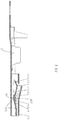
- FIG. 1 is a perspective view of the dual elastic plate connector in accordance with an embodiment of the present invention.
- FIG. 2 is a sectional view of the dual elastic plate connector in accordance with an embodiment of the present invention.
- FIG. 1 and FIG. 2 By reference to FIG. 1 and FIG. 2 , following detailed description provide illustration of embodiments of the present invention. However, the present invention is not limited by the description.
- a dual elastic plate connector comprises an engagement portion 1 and a combination portion 2 .
- the engagement portion 1 is engaged with another connector; the engagement portion includes a first elastic plate 11 , a second elastic plate 12 , and a protrusion part 13 .
- the combination portion 2 is combined with a cable
- the first elastic plate 11 comprises a head portion 111 and a stem portion 112 , with a curve structure 113 as a connection portion connected between the head portion 111 and the stem portion 112 .
- the second elastic plate 12 comprises a head portion 121 and a stem portion 122 , with a curve structure 123 as a connection portion connected between the head portion 121 and the stem portion 122 .
- a bending direction of the bending structure 113 of the first elastic plate 11 is in opposite to a bending direction of the bending structure 123 of the second elastic plate 12 .
- the stem portion 112 of the first elastic plate 11 overlaps the head portion 121 of the second elastic plate 12 .
- the protrusion part 13 is disposed on an inner wall of the engagement portion 1 .
- a terminal of the other connector is inserted between the first elastic plate 11 and the protrusion part 13 and contacts the stem portion 112 of the first elastic plate 11 .
- the first elastic plate 11 is deformed and abuts against the head portion 121 of the second elastic plate 12 .
- the engagement portion 1 of the dual elastic plate connector further comprises a first curve member 14 and a second curve member 15 .
- An end of the first curve member 14 is connected with a lateral side of the head portion 111 of the first elastic member 11 , and another end of the first curve member 14 is connected with a first engagement end 16 of the engagement portion 1 .
- An end of the second curve member 15 is connected with a lateral side of the stem portion 122 of the second elastic member 12 , and another end of the second curve member 15 is connected with a second engagement end 17 of the engagement portion 1 .
- the engagement portion 1 comprises a curve block plate 18 disposed on an engagement end of the engagement portion 1 .
- the combination portion 2 comprises a plane tube 21 , a square block plate 22 , an expanding tube 23 , a tapering block plate 24 , and a wire press ring 25 .
- the wire press ring 25 is disposed on a junction between the combination portion 2 and the engagement portion 1 and comprises a press plate 26 and a block plate 27 ; the plane tube 21 is disposed between the wire press ring 25 and the square block plate 27 .
- the square block plate 22 and the expanding tube 23 disposed at a middle portion of the combination portion 2 ; the square block plate 22 is positioned between the plane tube 21 and the expanding tube 23 .
- the tapering block plate 24 is disposed on an end part of the combination portion 2 .
Landscapes
- Details Of Connecting Devices For Male And Female Coupling (AREA)
Abstract
Description
Claims (3)
Priority Applications (1)
| Application Number | Priority Date | Filing Date | Title |
|---|---|---|---|
| US16/905,004 US11223149B1 (en) | 2020-06-18 | 2020-06-18 | Dual elastic plate connector |
Applications Claiming Priority (1)
| Application Number | Priority Date | Filing Date | Title |
|---|---|---|---|
| US16/905,004 US11223149B1 (en) | 2020-06-18 | 2020-06-18 | Dual elastic plate connector |
Publications (2)
| Publication Number | Publication Date |
|---|---|
| US20210399453A1 US20210399453A1 (en) | 2021-12-23 |
| US11223149B1 true US11223149B1 (en) | 2022-01-11 |
Family
ID=79022026
Family Applications (1)
| Application Number | Title | Priority Date | Filing Date |
|---|---|---|---|
| US16/905,004 Active US11223149B1 (en) | 2020-06-18 | 2020-06-18 | Dual elastic plate connector |
Country Status (1)
| Country | Link |
|---|---|
| US (1) | US11223149B1 (en) |
Citations (2)
| Publication number | Priority date | Publication date | Assignee | Title |
|---|---|---|---|---|
| US20080070452A1 (en) * | 2006-08-11 | 2008-03-20 | Ryuichi Komiyama | Female Contact |
| US7938695B2 (en) * | 2009-01-08 | 2011-05-10 | Sumitomo Wiring Systems, Ltd. | Terminal fitting |
-
2020
- 2020-06-18 US US16/905,004 patent/US11223149B1/en active Active
Patent Citations (2)
| Publication number | Priority date | Publication date | Assignee | Title |
|---|---|---|---|---|
| US20080070452A1 (en) * | 2006-08-11 | 2008-03-20 | Ryuichi Komiyama | Female Contact |
| US7938695B2 (en) * | 2009-01-08 | 2011-05-10 | Sumitomo Wiring Systems, Ltd. | Terminal fitting |
Also Published As
| Publication number | Publication date |
|---|---|
| US20210399453A1 (en) | 2021-12-23 |
Similar Documents
| Publication | Publication Date | Title |
|---|---|---|
| JP7395112B2 (en) | female terminal | |
| US8262419B2 (en) | Contact for electric connector and method of making the same | |
| US10903610B1 (en) | Self-lock structure of Ethernet connector for vehicle | |
| TW201126725A (en) | Terminal box for solar cell module | |
| JP2013506243A (en) | Improved clamp for connecting to the electrode of an electric battery | |
| WO2010024033A1 (en) | Terminal metal fitting and method of manufacturing terminal metal fitting | |
| US11081825B1 (en) | Double-pole butting connector | |
| JP2022179754A (en) | female terminal | |
| US20250030188A1 (en) | Terminal unit, female terminal, and male terminal | |
| US6905371B2 (en) | Terminal and connector using same | |
| EP2761701B1 (en) | Female terminal | |
| CN109980370B (en) | Connector | |
| WO2016029885A2 (en) | "8"-shaped elastic contact element and electrical connector using said contact element | |
| US11223149B1 (en) | Dual elastic plate connector | |
| CN211045808U (en) | Novel combined contact part | |
| KR20160107938A (en) | Cable type secondary battery | |
| CN208782088U (en) | Terminal of power connector | |
| CN111697369A (en) | Heavy current contact terminal and high-voltage connector | |
| JP2013118102A (en) | Female terminal structure | |
| US7249970B1 (en) | Connector for coaxial cable | |
| CN109004478A (en) | A kind of wire jointing clamp | |
| CN223638652U (en) | A combined conductive terminal and electrical connector | |
| US7931492B1 (en) | Structure of conductive terminal of electrical connector | |
| CN208939239U (en) | Connector | |
| WO2016029886A1 (en) | Elastic contact spring and adapter using the contact spring |
Legal Events
| Date | Code | Title | Description |
|---|---|---|---|
| FEPP | Fee payment procedure |
Free format text: ENTITY STATUS SET TO UNDISCOUNTED (ORIGINAL EVENT CODE: BIG.); ENTITY STATUS OF PATENT OWNER: SMALL ENTITY |
|
| AS | Assignment |
Owner name: AMPHENOL EAST ASIA ELECTRONIC TECHNOLOGY (SHEN ZHEN) CO., LTD., CHINA Free format text: ASSIGNMENT OF ASSIGNORS INTEREST;ASSIGNORS:HE, DAN-REN;LI, DE-MING;REEL/FRAME:053064/0627 Effective date: 20200506 |
|
| FEPP | Fee payment procedure |
Free format text: ENTITY STATUS SET TO SMALL (ORIGINAL EVENT CODE: SMAL); ENTITY STATUS OF PATENT OWNER: SMALL ENTITY |
|
| STCF | Information on status: patent grant |
Free format text: PATENTED CASE |
|
| FEPP | Fee payment procedure |
Free format text: ENTITY STATUS SET TO UNDISCOUNTED (ORIGINAL EVENT CODE: BIG.); ENTITY STATUS OF PATENT OWNER: LARGE ENTITY |
|
| MAFP | Maintenance fee payment |
Free format text: PAYMENT OF MAINTENANCE FEE, 4TH YEAR, LARGE ENTITY (ORIGINAL EVENT CODE: M1551); ENTITY STATUS OF PATENT OWNER: LARGE ENTITY Year of fee payment: 4 |